Article

Enhancement of the Al/Mg Dissimilar Friction Stir Welding Joint Strength with the Assistance of Ultrasonic Vibration

MOE Key Lab for Liquid-Solid Structure Evolution and Materials Processing, Institute of Materials Joining, Shandong University, Jinan 250061, China
*
Author to whom correspondence should be addressed.
Metals 2021, 11(7), 1113; https://doi.org/10.3390/met11071113
Submission received: 15 June 2021 / Revised: 4 July 2021 / Accepted: 6 July 2021 / Published: 12 July 2021
(This article belongs to the Special Issue Friction Stir Welding of Lightweight Alloys)

Abstract

:
The assistance of ultrasonic vibration during the friction stir welding (FSW) process has been verified as an effective approach for the improvement of joint strength. In the present study, experimentation on Al/Mg dissimilar alloys in butt joint configuration is implemented by employing FSW with and without the assistance of ultrasonic vibration. An optimized tool shoulder diameter of 12 mm is utilized, and the ultrasonic vibration is applied perpendicularly onto the tool along the welding direction, which is named UVaFSW. The results of joint appearance and macrostructure, characteristics of the intermetallic compounds (IMCs), as well as joint strength and fracture appearance are compared between Al/Mg FSW joints with and without ultrasonic vibration. It is demonstrated that the material intermixing between Al and Mg alloys is substantially strengthened in the UVaFSW joint compared with that in the FSW joint. Additionally, the ultrasonic vibration can be beneficial for the reduction of IMC thickness, as well as the formation of intermittently distributed IMC phases at the Al–Mg bonding interface. Consequently, the mechanical properties of Al/Mg FSW joints are significantly improved with the assistance of ultrasonic vibration. The maximum ultimate tensile strength is 206 MPa at tool rotation speed of 800 rpm and welding speed of 50 mm/min for the Al/Mg UVaFSW joint.

1. Introduction

For the purpose of environmental protection and energy saving, aluminum (Al) and magnesium (Mg) alloys have shown great potential in aerospace, automobile and railway transit industries as constituent parts of lightweight structures [1,2,3,4]. Therefore, the requirement for the dissimilar Al/Mg joining components is sustainably increasing [3,4]. However, due to the significant differences in physical properties, crystal structures and solubility between Al and Mg, joining of Al/Mg alloys by using fusion-based welding processes could lead to the excessive formation of hard and brittle intermetallic compounds (IMCs), as well as other defects such as pores, inclusion and hot cracks in the joint, which brings serious destruction to the Al/Mg joining strength [5,6,7].
As a solid-state joining technique, friction stir welding (FSW) provides lower heat input by comparing with fusion-based welding processes, so the formation of IMCs can be restricted dramatically and the cracking tendency can be controlled within a certain extent for joining dissimilar materials [1]. Numerous experimental studies in recent years have demonstrated that tool profile, tool rotation speed, welding speed and relative position of Al/Mg plates significantly influence on heat generation, plastic material flow and intermixing between Al and Mg, type of reaction at Al–Mg bonding interface, as well as macro-/microstructure and mechanical properties of the Al/Mg dissimilar FSW joint [1,4]. Moreover, it has been generally indicated that Al/Mg joint strength is highly connected with two main factors, i.e., material intermixing condition of Al/Mg alloys and characteristics of Al-Mg IMC distribution [1,2,4]. Malarvizhi et al. [8] divided the Al–Mg bonding interface into four regions from the top to the bottom of the weld cross-section, which are shoulder influenced region, transition region, pin influenced region and swirl zone, respectively. Both Zettler et al. [9] and Dorbane et al. [10] observed that the Al–Mg bonding interface is flexural and legible, the material intermixing between Al and Mg is intricate, and the formation of IMCs at the Al–Mg bonding interface is still inevitable during FSW process. McLean et al. [11] found divorced lamellar eutectic containing Al12Mg17 and α-Mg at the Al–Mg bonding interface by placing Mg on the retreating side (RS), but the Al/Mg FSW joint exhibited virtually no ductility. Firouzdor and Kou [12,13] obtained better macrostructure of Al/Mg dissimilar joint by placing Mg on the advancing side (AS) and found that the heat input in Al/Mg FSW is lower than that in both Al/Al and Mg/Mg FSW, which suggested that the intermixing stirring of the Al-Mg mixture can cause the formation of liquid films as well as the brittle IMC phase Al3Mg2 and Al12Mg17 upon solidification. Sato et al. [14] also observed eutectic structure consisting of Al12Mg17 and α-Mg by placing Mg plate on the AS and considered the formation of IMCs as a result of constitutional liquation during FSW process. Yamamoto et al. [15] obtained defect free Al/Mg FSW joint by placing Mg on the RS and observed twin-layer of the IMC phase which consisted of Al3Mg2 and Al12Mg17 at the Al–Mg bonding interface. It was considered that the formation and the growth of the IMC layer was controlled by the diffuse reaction between Al and Mg atoms, instead of eutectic reaction. Fu et al. [16] measured and analyzed the heat input in Al/Mg dissimilar FSW and found that friction coefficient, liquation tendency and deformability between Al and Mg could be completely different with variable relative positions of Al/Mg plates. Sound Al/Mg FSW joint was obtained at an intermediate tool rotation speed of 600–800 rpm and low welding speed of 30–60 mm/min by placing Mg on the AS and the tool offsetting 0.3 mm into Mg. Additionally, the formation of IMC phase Al3Mg2 and Al12Mg17 was also supposed to be as a result of the eutectic reaction.
Although the Al/Mg joint performance by the FSW process is prominently improved by comparing with that of fusion-based welding processes, the existence of hard and brittle IMCs still weakens the joint strength. Therefore, some researchers developed certain modifications of the conventional FSW process with the assistance of secondary energy sources. Zhao et al. [17] and Mofid et al. [18,19] performed Al/Mg FSW under water and liquid nitrogen, respectively. It was found that the thickness of IMC layers can be significantly suppressed due to lower heat input and the tensile strength of dissimilar Al/Mg joints can also be improved. Chang et al. [20] employed 2 kW laser power as auxiliary source and with 0.5 mm thick Ni foil as interlayer to reduce the contact between Al and Mg. The results showed that the formation of less brittle Ni-based IMC phases instead of Al12Mg17 could result in an improved tensile strength of the dissimilar Al/Mg FSW joint. However, it is evident that the FSW experiment in water or liquid nitrogen environment is complicated and costly. The laser hybrid FSW has the problem of low utilization of energy due to the reflection of laser on the non-ferrous metals and could impair the advantage of conventional FSW as a green manufacturing technique.
Ultrasonic energy is a clean high-frequency acoustic energy and is capable of reducing the resistance to deformation and facilitating the plastic material flow. Recently, ultrasonic vibration has been successfully utilized as an auxiliary energy for the assistance of FSW for the joining of Al/Al [21,22,23,24], Al/Cu [25,26,27] and Al/steel [28,29] alloys. Additionally, various transmission methods between ultrasonic vibration and the FSW process have also been developed for the joining of Al/Mg dissimilar alloys. Ji et al. [30] and Liu et al. [31] placed the ultrasonic generator under Mg plate on the AS with a relatively higher ultrasonic energy of 1600 W. It was found that the material intermixing between Al and Mg was enhanced, and the mechanical properties of the Al/Mg joint was improved with the assistance of ultrasonic energy. Lv et al. [32,33] and Zhao et al. [34,35] employed ultrasonic vibration enhanced FSW process for Al/Mg joining and observed that the ultrasonic energy in front of the tool had a preheating effect on the joint. The thickness of the IMC layer was dramatically decreased with the assistance of ultrasonic vibration, which was beneficial for the improvement of joint strength. Kumar et al. [36,37,38] applied ultrasonic vibration perpendicularly onto the tool for joining dissimilar Al/Mg alloys and found that the thermal effect of ultrasonic energy is negligible. Additionally, the ultrasonic vibration can be effective for the suppression of IMC growth, and the mechanical properties increased by over 22% with ultrasonic assistance [37]. However, although the ultrasonic vibration was found to be beneficial for the Al/Mg dissimilar FSW process, the maximum tensile strength of the Al/Mg dissimilar joint was limited to a value of ~178 MPa [33], which was relatively lower compared with that of the base material.
Accordingly, it can be concluded that both the transmission methods of ultrasonic vibration and the FSW factors are of great importance for achieving higher mechanical properties of Al/Mg dissimilar FSW joint. Therefore, the present study carries out FSW of dissimilar Al/Mg alloy with and without ultrasonic vibration by utilizing an optimized shoulder diameter of 12 mm and applying the ultrasonic vibration perpendicularly onto the tool, as suggested by Lv et al. [33] and Kumar et al. [37], respectively. Comparisons of joint appearance and macrostructure, characteristics of IMCs, as well as joint strength and fracture appearance are implemented between Al/Mg dissimilar FSW joints with and without ultrasonic vibration. Particularly, the correlation of Al/Mg dissimilar FSW joint mechanical properties with macroscopic material intermixing and IMC distribution with and without ultrasonic vibration are also discussed.

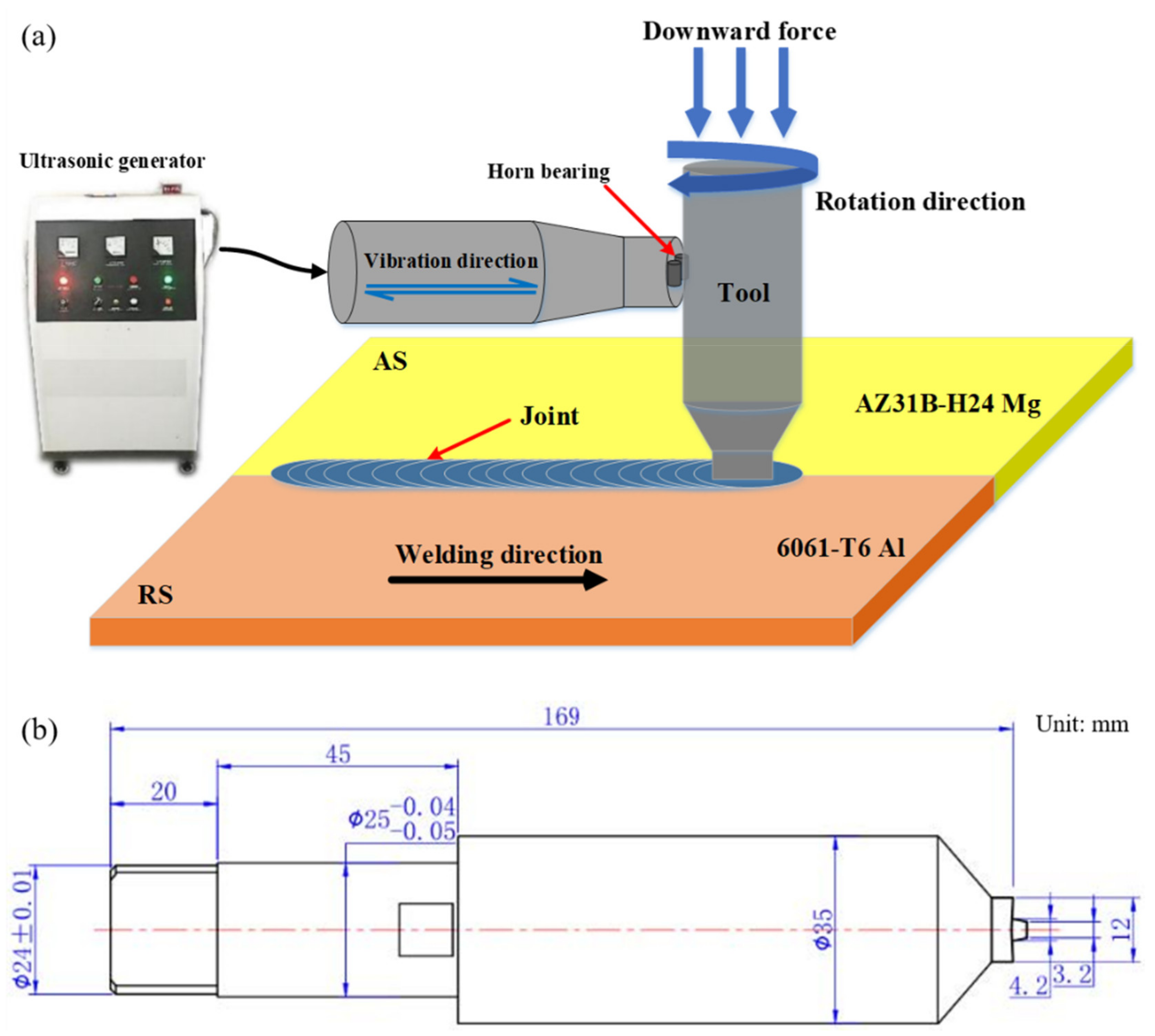
2. Materials and Experimentations

In the present study, dissimilar AA6061-T6 Al alloy and AZ31B Mg alloy were friction stir welded with and without ultrasonic vibration in butt joint configurations. The workpiece dimensions of both Al and Mg plates were 200 mm length, 65 mm width and 3.0 mm thickness. Table 1 lists the chemical compositions of the two alloys, which were obtained from the manufacturer. As schematically shown in Figure 1a, the ultrasonic energy was transmitted perpendicularly onto the tool through a pair of horns bearing with a distance of about 130 mm away from the tool shoulder. This process was named UVaFSW (ultrasonic vibration assisted FSW) [23]. The ultrasonic horn vibrated with a frequency of ~20 kHz and an amplitude of ~25 μm. The material of the FSW tool was H13 tool steel. The tool was schematically shown in Figure 1b. It was composed of a concave smooth shoulder with diameter of 12.0 mm and a right-hand threaded pin with length, root and tip diameter of 2.8, 4.2 and 3.2 mm, respectively. During both FSW and UVaFSW experiments, the Al alloy and Mg alloy were invariably placed on the RS and the AS, respectively. Additionally, the tool was shifted 0.3 mm away from the Al/Mg joining interface into the Mg alloy. The tool tilt angle was kept at 2.5° and the plunging depth of the shoulder into the workpiece top surface was 0.1 mm. The tool rotation speed was 800 rpm and the welding speeds were 30, 40, 50, 60 and 70 mm/min.
After the welding experiments, the joint surface morphological feature was firstly investigated by using laser scanning confocal microscope (LSCM, type LSM800, Carl Zeiss, Germany). Secondly, the cross-sections of both FSW and UVaFSW joints were cut by electric spark wire cutting machine for preparing the metallographic specimens. Then, the specimens were polished and etched by Keller reagent (1 mL HF + 2.5 mL HNO3 + 1.5 mL HCL + 95 mL H2O) and picric acid solution (13 g picric acid + 20 mL acetic acid + 200 mL ethanol) for Al side and Mg side, respectively. The macrostructures of the joint cross-sections were observed and photographed by optical microscope (Eclipse LV150, Nikon, Tokyo, Japan), while the IMC characteristics were analyzed by scanning electron microscope (JSM-7800F, JEOL, Tokyo, Japan) equipped with energy-dispersive X-ray spectrometer (JXA-8530F PLUS, JEOL, Tokyo, Japan) to identify the IMC phase. The tensile testing specimens of both FSW and UVaFSW joints were also prepared for the evaluation of the joint strength, and the dimensions of the specimens were schematically presented in Figure 2. Moreover, the tensile tests were implemented on type CMT-50 universal tensile testing machine with the maximum tensile force of 50 KN and displacement rate of 1.0 mm/min. The tensile tests for each welding parameter were carried out at least three times to ensure that the measured results were credible, and finally the average values were utilized.

3. Results and Discussion

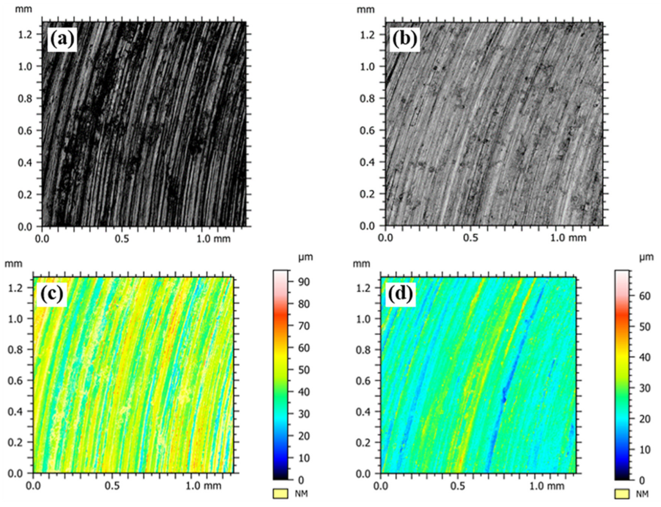
3.1. Joint Appearance and Macrostructure

The morphological features of the joint surface produced by FSW and UVaFSW for tool rotation speed of 800 rpm and welding speed of 50 mm/min are shown in Figure 3. It can be seen that the arc banded features are visible in both FSW and UVaFSW joints, and the surface perfection of FSW joint is improved with the assistance of ultrasonic vibration by visual impression from the figures without the filtering processing shown in Figure 3a,b for the joints of FSW and UVaFSW, respectively. More quantized information about the surface roughness of the joints can be obtained from the colorized figures after filtering processing, as shown in Figure 3c,d for FSW and UVaFSW, respectively. It can be observed that the fluctuation height of the surface is over 50 μm for the FSW joint, while the value dramatically decreases to under 30 μm for the UVaFSW joint. Statistically, the arithmetical average height of the surface roughness is 5.93 μm and 3.60 μm for the joints of FSW and UVaFSW, respectively, which provides a solid evidence for the beneficial efficiency of the surface appearance with the assistance of ultrasonic vibration. For the formation of the arc banded feature on the FSW joint surface, it has been attributed to the periodic up-and-down motion of the tool, which is generally micron-sized but is considered as an inherent behavior of FSW process [39,40]. In the UVaFSW process, the acoustic horn is applied vertically to the tool, and ultrasonic vibration is kept along the welding direction with an amplitude about 25 μm. As a result, it causes an accessional reciprocating motion in addition to the forward motion of the tool, so the joint surface can interact with the tool shoulder repeatedly. On the other hand, it was found in the Al/Mg FSW experiment that the adhesion between the tool and the mixed Al-Mg material is substantial, which generates a negative influence on the joint surface roughness. For the UVaFSW process, the ultrasonic vibration could be contributed to reduce the adhesion of the Al-Mg mixture on the shoulder. Finally, the appearance of the UVaFSW joint is promoted distinctly by comparing with that of the FSW joint.
Figure 4 presents the macrostructure of the joint cross-sections produced by FSW and UVaFSW processes for tool rotation speed of 800 rpm and welding speeds from 30 to 70 mm/min. At low welding speed of 30 mm/min, it is shown that the material intermixing between Al and Mg is evident in the stirring zone for both FSW and UVaFSW joints, as can be seen in Figure 4a,b, respectively. The plasticized Al strips flow through the RS and incorporate into the Mg matrix on the AS, especially at the location close to the shoulder. It is no doubt that the sufficient mixture between Al and Mg along the thickness direction of the joint enlarges the contact area of dissimilar materials, and could be helpful for increasing the joint strength. However, at the location away from the shoulder, as the joint interface between Al and Mg is offset to the Mg side, plenty of fine Al bands are found to be homogeneously distributed in the Mg Matrix, which could be caused by the drastic stirring action of the pin threads during the tool rotating.
With welding speed increasing to 40 and 50 mm/min, the macrostructure of the FSW joint is clearly different. As shown in Figure 4c,e, the plasticized Al strip into the Mg matrix in the shoulder affected region is absent, replaced by a legible and flexural S-curve at the interface between Al and Mg in the stirring zone. The mean reason for this is that the plasticity of Al is reduced due to the decreasing heat input with increasing welding speed. However, the macrostructures of UVaFSW joints at welding speeds of both 40 and 50 mm/min are found to be analogical with that at 30 mm/min, as can be seen in Figure 4d,f, respectively. It could be attributed to the flow stress reduction of both Al and Mg according to the acoustic softening effect of ultrasonic vibration [41]. As a result, it is appropriate to maintain the plasticity of the Al strips and accomplish the intermixing with the Mg matrix in the shoulder affected region, regardless of the decreasing heat input.
At welding speed of 60 mm/min, the bonding interface between Al and Mg transforms into a distinct skew line in the stirring zone for both FSW and UVaFSW joints, as can be seen in Figure 4g,h, respectively. It is shown that the plasticized Al strips are much smaller, which indicates that the intermixing of Al strips into the Mg matrix is weakened dramatically compared with that at lower welding speeds. With the further increasing of welding speed to 70 mm/min, a clear void defect can be observed on the AS in the Mg matrix of FSW joint, as shown in Figure 4i. According to the measured results by Fu et al. [16], the temperature in the stirring zone could be approximately 50 °C lower by increasing welding speed from 30 to 70 mm/min. As a result, it is evident that the plastic material flow is seriously inadequate with the decreasing heat input. However, no macroscopic defect was found in the macrostructure of the UVaFSW joint shown in Figure 4j, which provides more evidence that the ultrasonic vibration is efficient for reducing the material flow stress, enhancing the plastic deformation and intermixing Al and Mg in the stirring zone.

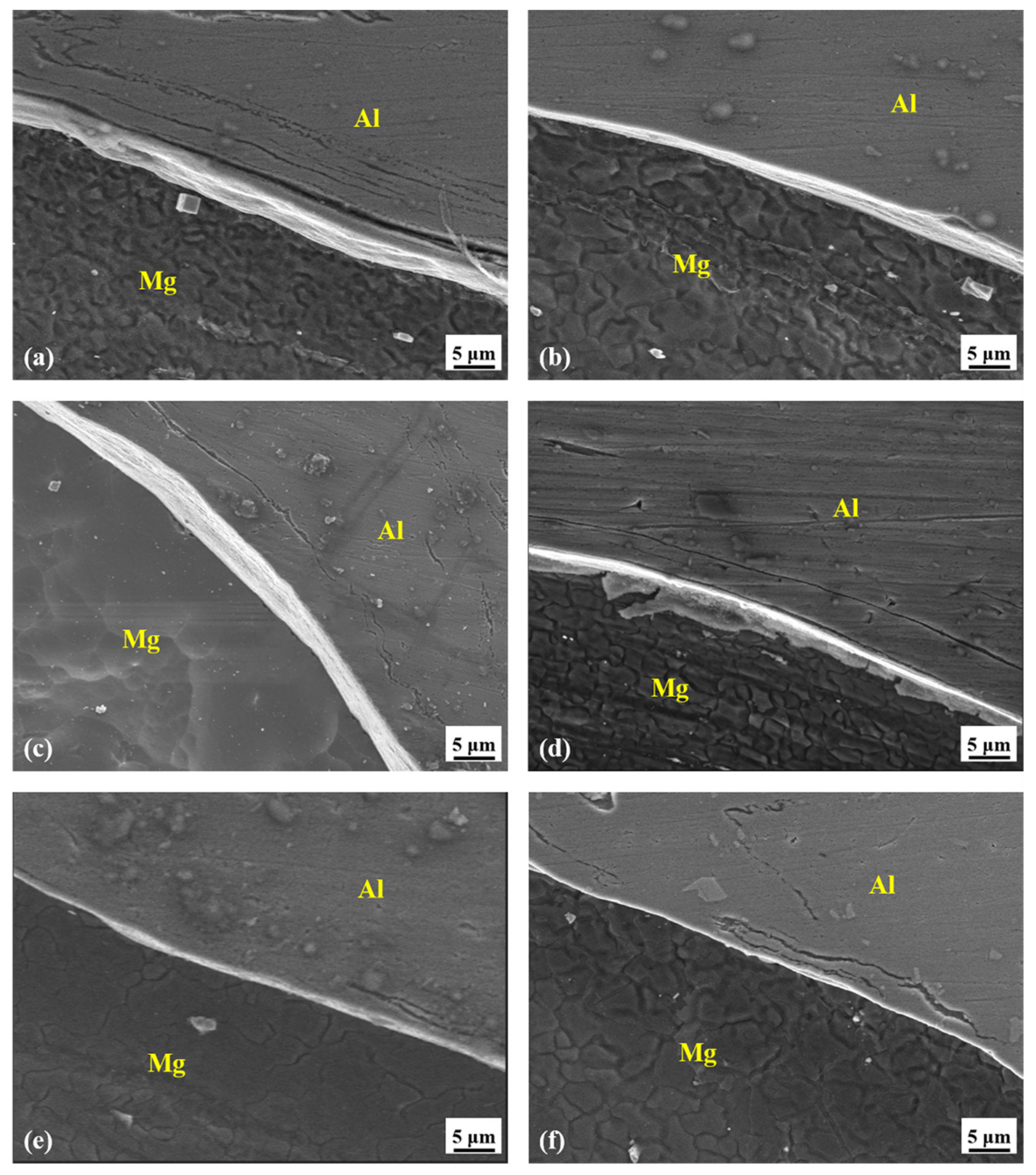
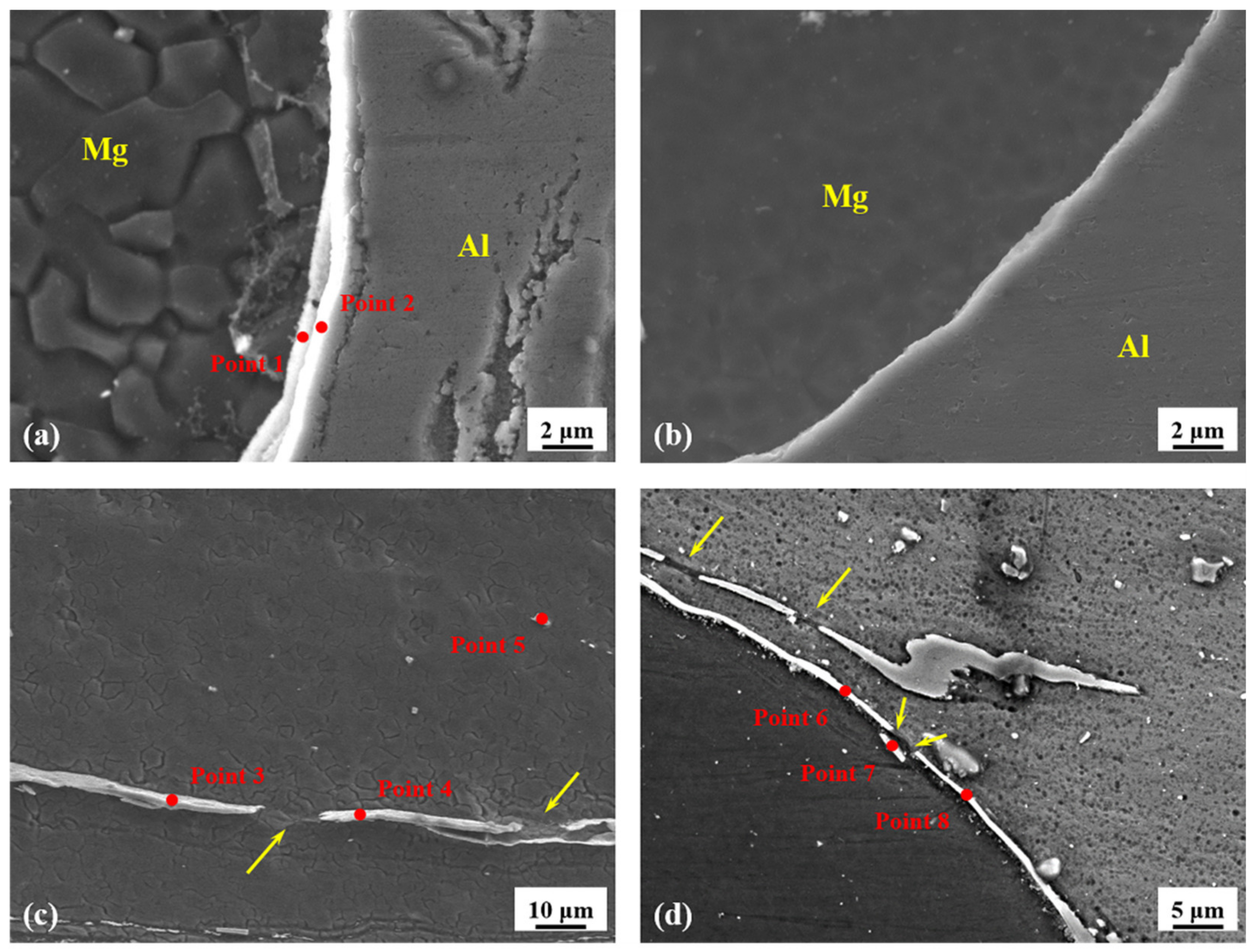
3.2. Characteristics of IMCs

According to the observation of the macrostructure of both FSW and UVaFSW joints, it is evidently shown that the material intermixing between Al and Mg shows its existence throughout the stirring zone, so the distribution of IMCs in the joint could be varied from one location to another. Therefore, two typical regions are explored in this subsection for Al/Mg FSW and UVaFSW joints with tool rotation speed of 800 rpm and welding speed of 50 mm/min. One region is located at the Al–Mg bonding interface, as presented in Figure 5 and Figure 6. The other region is located in the pin affected region where numerous Al bands are homogeneously distributed in the Mg matrix, which is shown in Figure 7.
In Figure 5, the thickness of the IMCs, which is continuously distributed along the Al–Mg bonding interface, can be measured at the locations of 0.6 (Figure 5a,b), 1.4 (Figure 5c,d) and 2.5 mm (Figure 5e,f) away from the top surface for both FSW and UVaFSW joints, respectively. It can be observed that the average thicknesses of the IMC layers are ~4.5, 3.7 and 2.4 μm, respectively, with the distance from the top surface increasing for the FSW joint. However, by applying ultrasonic vibration to the rotating tool, the average thickness of the IMC layer decreases significantly by 42.2%, 59.5% and 58.3% to values of ~2.6, 1.5 and 1.0 μm, respectively, at the corresponding locations. The previous studies have widely indicated that there are two main mechanisms for the formation of Al-Mg IMC layer during the FSW process [12,13,14,15,16]. One mechanism is the eutectic reaction according to the Al-Mg binary alloy phase diagram [12,13,14]. Although FSW is a solid-state welding process, there is still a certain amount of constitutional liquation happening at the tool–workpiece interface during the dissimilar joining between Al and Mg. The temperatures of eutectic transformation are 450 and 437 °C for L → Al3Mg2 + α-Al and L → Al12Mg17 + α-Mg, respectively. The other mechanism is the atomic diffusion between Al and Mg in the vicinity of the tool under conditions of high strain rate and pressure, and below the eutectic transformation temperature of the Al-Mg system [15]. As the plastic material flow and intermixing between dissimilar materials around the tool is complicated, and the difference of the eutectic reaction temperature of Al-Mg is only 13 °C, the nucleation and the growth of the Al-Mg IMC phase is still controversial so far.
During the FSW process, the material on the leading side flows towards the RS and is extremely squeezed with the rotation of the tool. Additionally, the temperature in this region also achieves a high level, which facilitates the plastic deformation, as well as the reactions between dissimilar materials. In the present experiment, Mg is placed on the AS and Al is placed on the RS. Some observations on the horizontal cross-section of the Al-Mg FSW exiting keyhole also have confirmed that the contents of Mg rotating with the tool are quite limited [34,35]. So, it is comprehensible that Al-rich area can be activated around the rotating tool on the RS. As a result, the Al3Mg2 phase is the most likely formed IMC in this region, and finally it appears at the Al–Mg bonding interface with the material deposited on the trailing side. Therefore, it is reasonable to consider that the single-layer IMCs in Figure 5 are phase Al3Mg2 rather than phase Al12Mg17. This inference has also been confirmed according to the EDS point scan results by Zhao et al. [34,35]. Some other researchers have also demonstrated that the thickness of the Al-Mg IMC layer could be much thinner with the assistance of ultrasonic vibration [32,33,34,35,36,37]. Moreover, the general consensus is that the formation mechanism of the IMC layer remains analogous with or without ultrasonic vibration during the FSW process. However, as shown in Figure 6, it was also found that the distribution of IMCs is extraordinary at some typical locations along the Al–Mg bonding interface. Table 2 lists the compositions for the points marked in Figure 6. In the region below the top surface of the FSW joint, a twin-layer IMC can be observed, as shown in Figure 6a. The EDS point analysis of the IMC component depicts that point 1 at the Mg-side layer consists of 53.8 at% Mg and 46.2 at% Al, while point 2 at the Al-side layer consists of 30.2 at% Mg and 69.8 at% Al. Hence, the IMC phase Al12Mg17 and Al3Mg2 can be identified for Mg-side layer and Al-side layer, respectively. A possible reason for the formation of the two IMC layers could be that the heat is accumulated in this region, and, meanwhile, the plastic material flow is restrained due to the relatively higher welding speed of 50 mm/min. As can be observed in Figure 4e, no plasticized Al strip is intermixed with the Mg matrix under the shoulder of the FSW joint, which facilitates the nucleation of Al12Mg17. Twin-layer IMCs in the Al/Mg FSW joint have also been reported by Yamamoto et al. [15] and Lv et al. [32]. On the contrary, the plastic material flow during the process with the assistance of ultrasonic vibration is more sufficient, as shown in Figure 4f, and no twin-layer IMCs have been detected in the present study. Figure 6b depicts the IMC layer at the location where the plasticized Al strips penetrate into the Mg matrix under the shoulder of the UVaFSW joint. It can be seen that the distribution of IMCs is single-layer and its thickness is below 1.0 μm, which is particularly lower than that at the Al–Mg bonding interface. This could be because the ultrasonic vibration helps to maintain a sound condition for the plastic material flow in this region and the IMC layer is elongated with the rotating of the shoulder during the UVaFSW process.
However, it is also found that there is a certain amount of scattered or discontinued IMCs in the Al/Mg UVaFSW joint, as shown in Figure 6c,d, respectively. With the plastic deformation of the mixed material in the shoulder affected zone, traces of Al bands with high plasticity and high temperature could penetrate into the Mg matrix and even be broken and sporadically distributed. Figure 6c presents an example of this phenomenon, and the three points are marked to determine the IMCs’ compositions by EDS point scan. As listed in Table 1, point 3 consists of 54.1 at% Mg and 45.6 at% Al, point 4 consists of 62.8 at% Mg and 36.7 at% Al, and point 5 consists of 64.0 at% Mg and 35.2 at% Al. Additionally, all of the three points contain slight O. Accordingly, the IMC phase Al12Mg17 can be recognized for all of points 3, 4 and 5, which could be because that the Al bands are surrounded by Mg-rich environment. Figure 6d shows the interruptions of the IMC layers at the Al–Mg bonding interface on the bottom of the UVaFSW joint. In this region, the pin threads have a strong effect on facilitating the downward motion of Al-Mg mixture, while the backing plate constrainedly restricts the plastic material flow. Consequently, the Al-Mg IMC layer is significantly impacted by the plastic deformation and could be broken in several locations. It can be observed from the EDS point scan results listed in Table 1 that point 6 consists of 39.4 at% Mg and 60.6 at% Al, point 7 consists of 33.9 at% Mg and 66.1 at% Al, and point 8 consists of 39.2 at% Mg and 60.8 at% Al. Therefore, the IMC phase Al3Mg2 can be identified in this area. It is worth mentioning that the discontinued IMC characteristics presented in Figure 6c,d have rarely been reported in the literature for Al/Mg FSW joints. The reason for the formation of discontinued IMCs could be vibratory action of the tool stimulated by the ultrasonic energy during the UVaFSW process. However, more detailed work should be carried out in the future for the underlying formation mechanism. It is assumed that the discontinued IMCs could prevent the crack propagation along the Al–Mg bonding interface and have a positive influence on the mechanical properties of the UVaFSW joint.
The pin threads have an intricate function on the plastic material flow, as well as the intermixing between Al and Mg in the stirring zone during the Al/Mg FSW process. On one hand, the asymmetrical feature of the threads provides additional shearing action on the plastic material in the vicinity of the tool. With the rotation of the tool, banded Al could be peeled off periodically from the Al matrix on the RS and then mixes with the Mg matrix on the AS. On the other hand, the pin threads could have a downward force component on the material flow [42,43]. Combining the above-mentioned two functions, the phenomenon that Al bands are dispersedly distributed in the Mg matrix is generally located on the AS and the lower part of the joint cross-section, as has been presented in Figure 4. One critical characteristic of the IMC bands in the Mg matrix is its geometric morphology, which is long and gracile, as demonstrated in Figure 7. Additionally, no evident difference for the distribution of the IMC bands can be observed between FSW and UVaFSW joints. The EDS point scan result of several typical regions shows that the bands in the Mg matrix are all composed of ~65 at% Mg and ~35 at% Al, which confirms that the IMC phase is Al12Mg17 for both FSW and UVaFSW joints. The dispersive IMC bands in the Mg matrix could be beneficial for increasing the local mechanical properties of the Al/Mg dissimilar FSW joint.

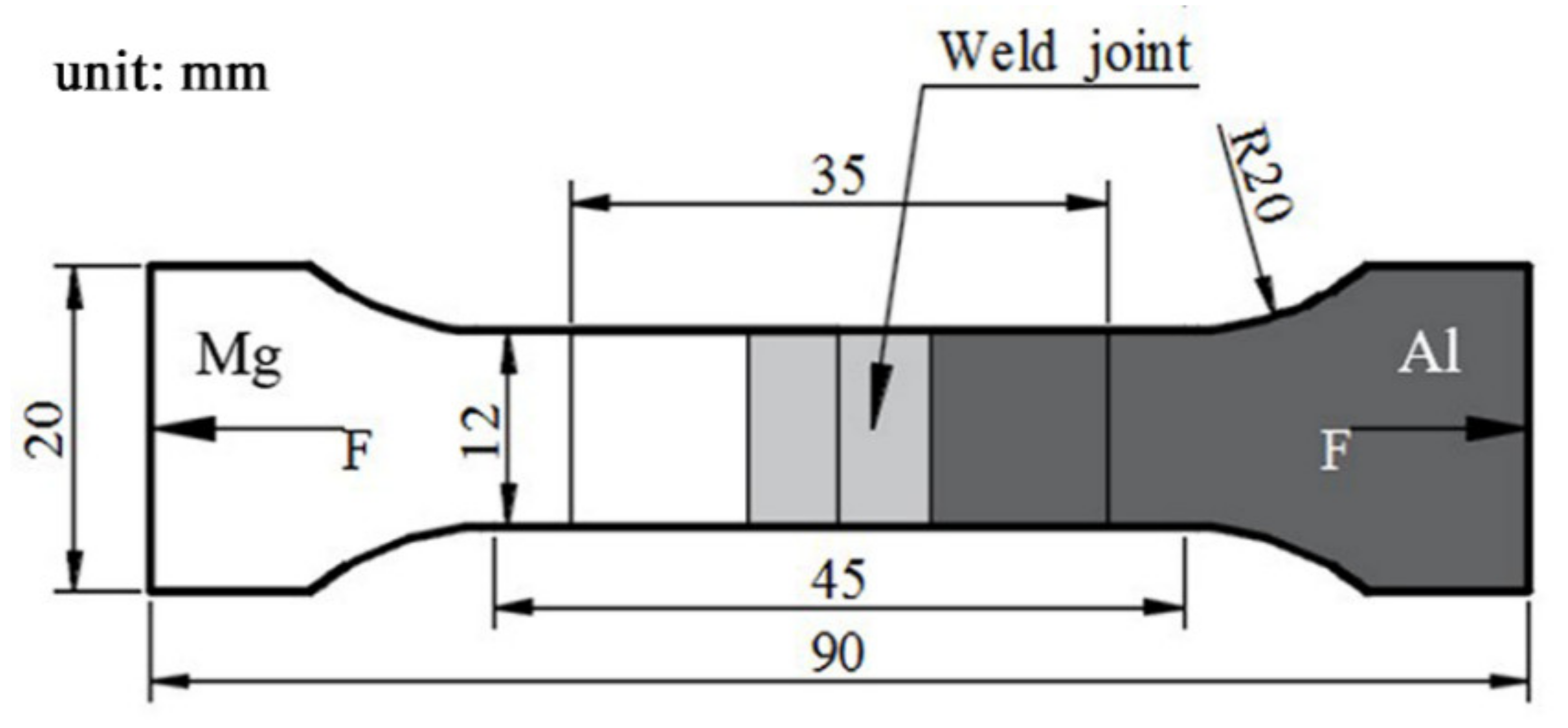
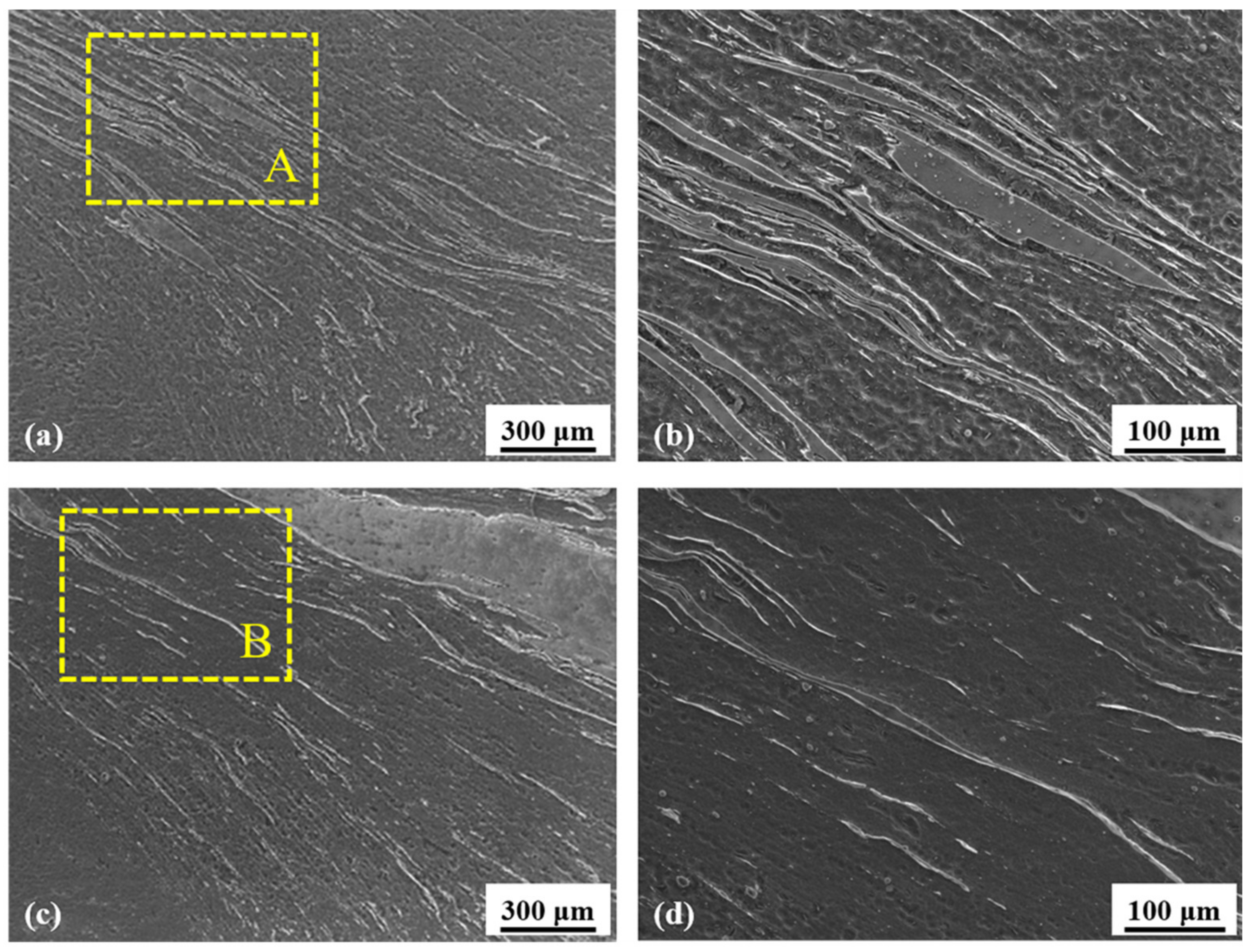
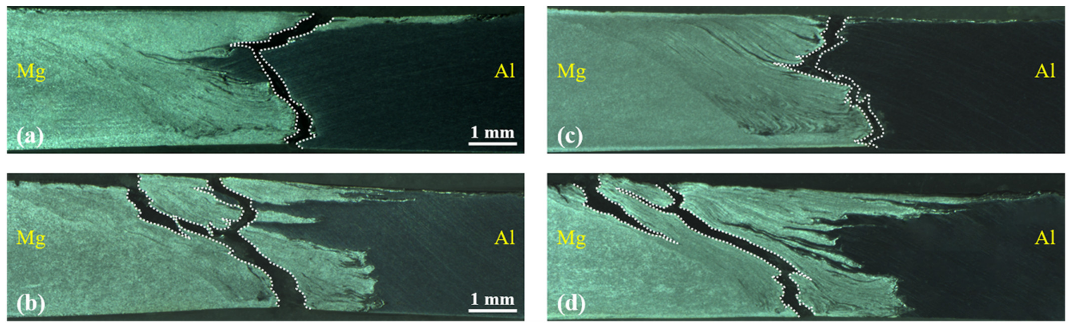
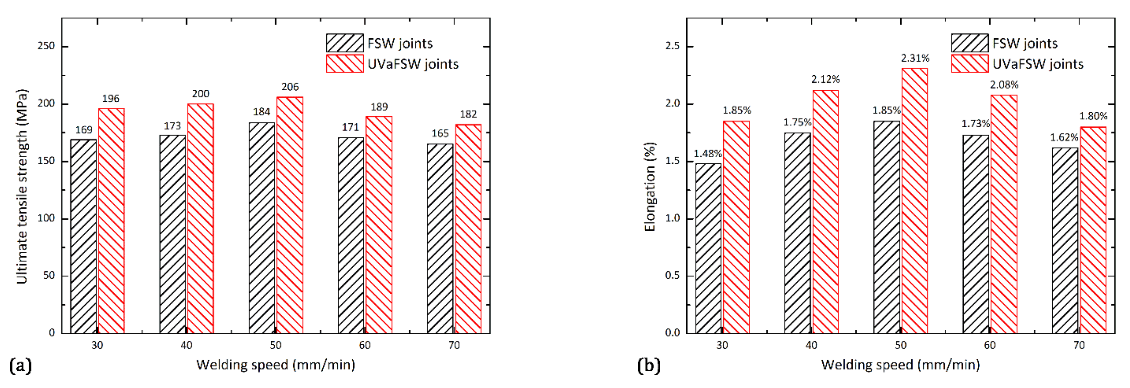
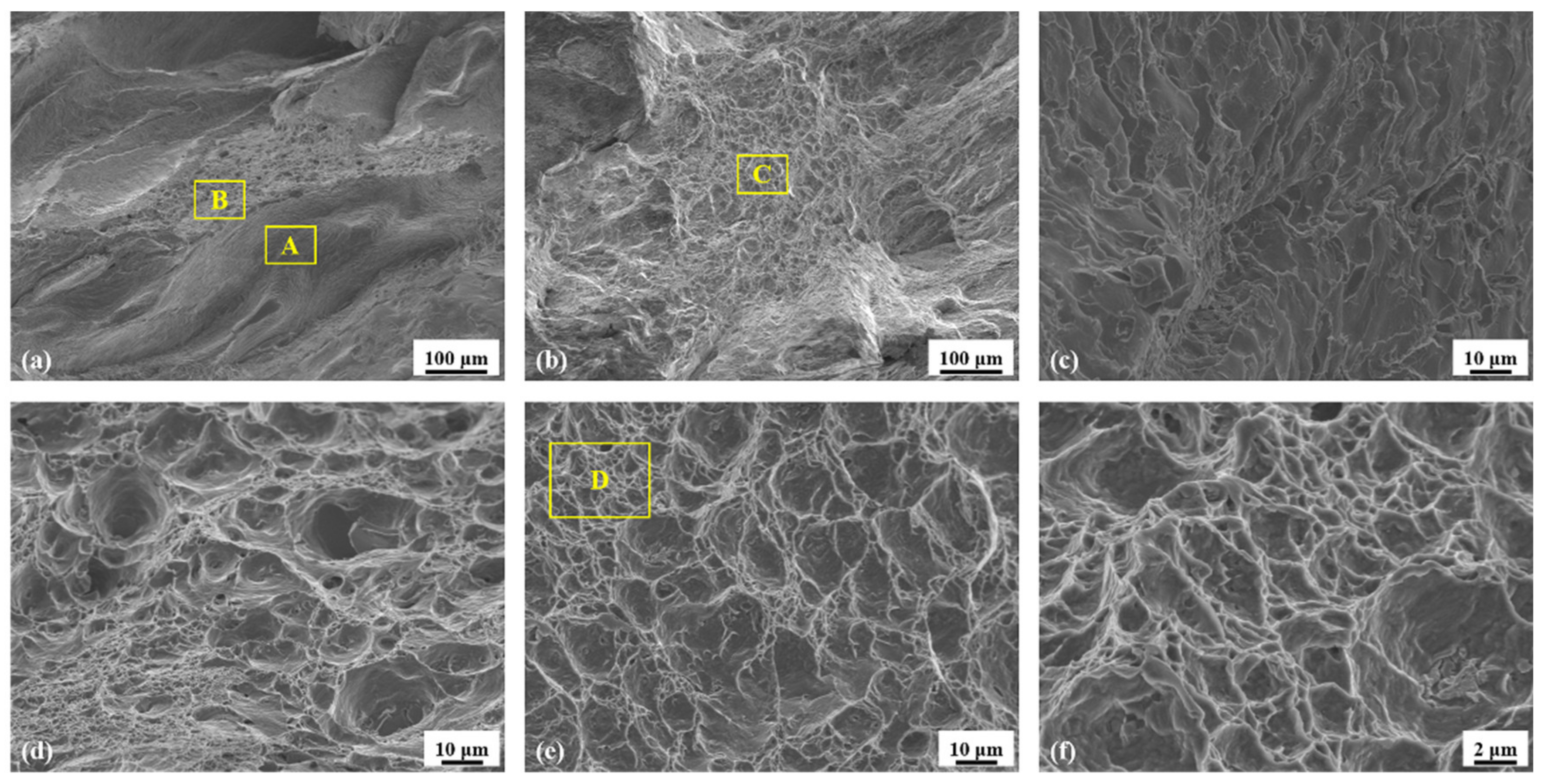
3.3. Tensile Strength and Fracture Appearance

Figure 8 shows the fracture behavior on the joint cross-section during the tensile test for both FSW and UVaFSW Al/Mg joints at tool rotation speed of 800 rpm and welding speeds of 40 and 50 mm/min. It can be observed that the crack propagations for FSW joints are both along the Al–Mg bonding interface, as illustrated in Figure 8a,c, respectively. However, the failure patterns for UVaFSW joints are completely different and two crack propagation modes can be found for both welding speeds, as shown in Figure 8b,d, respectively. One main fracture location is along the heat affected zone (HAZ) on the Mg side, while another subordinate crack originates from the top surface but without penetrating the bottom surface for both welding speeds. The difference in Al/Mg joint fracture behaviors with and without ultrasonic vibration could be related to the following three aspects. Firstly, the bonding interface between Al and Mg of the FSW joint is a interpretable S-curve, while a number of plasticized Al strips insert into the Mg matrix in the shoulder affected zone for the UVaFSW joint, so that the contact area of the Al–Mg bonding interface is increased dramatically according to the discussion on Figure 4. Secondly, it has been demonstrated in Figure 5 and Figure 6 that the hard brittle IMC layer is much thicker and consecutively distributed along the Al–Mg bonding interface of FSW joint than that of UVaFSW joint, which could be contributed to the propagation of the crack. The discontinuity of Al–Mg IMCs is generally located at the top or the bottom surface of UVaFSW joint cross-section as can be seen in Figure 6c,d, so the derivation of the crack can be prevented along the Al–Mg bonding interface. Another possible reason is that the grain size in the stirring zone can be refined with the assistance of ultrasonic vibration. The observations by Liu et al. [21], Gao et al. [44] and Padhy et al. [45] has provided sufficient evidences on the Al alloys FSW joint with the assistance of ultrasonic vibration. However, the work for Al/Mg dissimilar UVaFSW joint is still deficient in the literature, as well as in the present study. More in-depth testing about the grain size of Al-Mg mixture in the stirring zone, especially the grain orientation and texture on the Al–Mg bonding interface should be implemented in the future for more detailed information.
Apparently, it is no doubt that the tensile properties of Al/Mg joints by UVaFSW process can be improved by comparing with that by FSW process at tool rotation speed of 800 rpm, as plotted in Figure 9. Both the ultimate tensile strength and the elongation of the Al/Mg joints with or without ultrasonic vibration were found to increase with the increase in welding speed, and both achieve the maximum values at welding speed of 50 mm/min. As shown in Figure 9a, the maximum ultimate tensile strength is 180 MPa for FSW joint, which is 69.2% with respect to the Mg base material. With the assistance of ultrasonic vibration, the maximum ultimate tensile strength increases by ~14.4% to a value of 206 MPa for UVaFSW joint and a welding efficiency of 79.2% with respect to the Mg base material. It is evident that the tensile strength is higher than most reported data [15,16,30,31,32,33,36,37] and the positive contribution of ultrasonic vibration is also significant. However, the elongation is below 2.5% for both FSW and UVaFSW joints at welding speeds from 30 to 70 mm/min. The maximum elongation is only 1.85% for FSW joint, while the value increases by 24.9% to 2.31% for UVaFSW joint, as can be seen in Figure 9b. The poor ductility of Al/Mg joint has also be reported by McLean et al. [11] and could be attributed to the brittle Al-Mg IMC layers at the bonding interface of FSW joint. However, the elongation of UVaFSW joint is promoted distinctly, which could be a result of enhanced material intermixing between Al and Mg, as well as the reduction in the IMC layer thickness with the application of ultrasonic vibration.
Figure 10 shows the comparison of the fracture surface morphology between FSW and UVaFSW Al/Mg joints for tool rotation speed of 800 rpm and welding speed of 50 mm/min. The brittle–ductile mode can be observed in Figure 10a of the fracture surface for FSW joint and the magnification of typical brittle and ductile pattern is shown in Figure 10c,d, respectively. The brittle fracture pattern with tear ridges occupies most regions of the fracture surface, while large and small ductile dimples can also be found in some individual regions. As for UVaFSW joint, the ductile mode characteristics of the fracture surface is explicitly demonstrated in Figure 10b, and well-proportioned dimples are also evident according to the magnifications shown in Figure 10e,f. The improvement of the ductility for UVaFSW joint compared with that for FSW joint is mainly because the transformation of the fracture location and the reduction in IMC formation with the assistance of ultrasonic vibration.

4. Conclusions

In the present study, Al/Mg dissimilar alloys are friction stir welded with and without the assistance of ultrasonic vibration by utilizing an optimized tool shoulder diameter of 12 mm and applying the ultrasonic vibration perpendicularly onto the tool along the welding direction. The results of joint appearance and macrostructure, characteristics of IMCs, as well as joint strength and fracture appearance are compared between the Al/Mg dissimilar FSW joints with and without ultrasonic vibration. The following conclusions can be summarized:
  • The surface morphology of the Al/Mg FSW joint is improved with the assistance of ultrasonic vibration. The material intermixing between Al and Mg is enhanced in the UVaFSW joint compared with that in the FSW joint.
  • The thickness of the IMC layers at the Al–Mg bonding interface is significantly reduced with the assistance of ultrasonic vibration. Additionally, twin-layer IMC phases consisting of both Al12Mg17 and Al3Mg2 are observed in the shoulder affected zone of FSW joint, while a certain amount of scattered or discontinued IMC phases Al12Mg17 and Al3Mg2 are identified respectively in shoulder and pin affected zone of UVaFSW joint.
  • The maximum Al/Mg joint strength is achieved at tool rotation speed of 800 rpm and welding speed of 50 mm/min with the assistance of ultrasonic vibration. The value of ultimate tensile strength is 206 MPa and the ductility of Al/Mg UVaFSW joint is also conspicuously increased. The enhancement of the Al/Mg joint strength is considered as a combined effect of both the substantial material intermixing of dissimilar Al-Mg alloys and the ameliorative characteristics of the IMC distribution with the assistance of ultrasonic vibration.

Author Contributions

Conceptualization, Y.B., H.S. and C.W.; methodology, Y.B. and H.S.; formal analysis, Y.B. and H.S.; investigation, Y.B.; data curation, Y.B. and H.S.; writing—original draft preparation, Y.B. and H.S.; writing—review and editing, H.S. and C.W.; supervision, H.S. and C.W.; project administration, H.S. and C.W.; funding acquisition, H.S. and C.W. All authors have read and agreed to the published version of the manuscript.

Funding

This research was funded by the National Natural Science Foundation of China (grant numbers 52035005 and 52005297) and the Fundamental Research Funds of Shandong University (grant number 2019GN003).

Institutional Review Board Statement

Not applicable.

Informed Consent Statement

Not applicable.

Data Availability Statement

The data presented in this study are available on request from the corresponding author.

Acknowledgments

The authors acknowledge the financial support from the National Natural Science Foundation of China (Grant Nos. 52035005 and 52005297) and the Fundamental Research Funds of Shandong University (Grant No. 2019GN003).

Conflicts of Interest

The authors declare that there is no conflict of interest regarding the publication of this paper.

References

  1. Simar, A.; Avettand-Fènoël, M.N. State of the art about dissimilar metal friction stir welding. Sci. Technol. Weld. Join. 2017, 22, 389–403. [Google Scholar] [CrossRef]
  2. Shah, L.H.; Othman, N.H.; Gerlich, A. Review of research progress on aluminum-magnesium dissimilar friction stir welding. Sci. Technol. Weld. Join. 2018, 23, 256–270. [Google Scholar] [CrossRef]
  3. Liu, L.; Ren, D.; Liu, F. A review of dissimilar welding techniques for magnesium alloys to aluminum alloys. Materials 2014, 7, 3735–3757. [Google Scholar] [CrossRef] [Green Version]
  4. Singh, V.P.; Patel, S.K.; Ranjan, A.; Kuriachen, B. Recent research progress in solid state friction-stir welding of aluminium–magnesium alloys: A critical review. J. Mater. Res. Technol. 2020, 9, 6217–6256. [Google Scholar] [CrossRef]
  5. Liu, L.M.; Wang, H.Y.; Zhang, Z.D. The analysis of laser weld bonding of Al alloy to Mg alloy. Scr. Mater. 2007, 56, 473–476. [Google Scholar] [CrossRef]
  6. Liu, P.; Li, Y.; Geng, H.; Wang, J. Microstructure characteristics in TIG welded joint of Mg/Al dissimilar materials. Mater. Lett. 2007, 61, 1288–1291. [Google Scholar] [CrossRef]
  7. Wang, J.; Feng, J.C.; Wang, Y.X. Microstructure of Al-Mg dissimilar weld made by cold metal transfer MIG welding. Mater. Sci. Technol. 2008, 24, 827–831. [Google Scholar] [CrossRef]
  8. Malarvizhi, S.; Balasubramanian, V. Influences of tool shoulder diameter to plate thickness ratio (D/T) on stir zone formation and tensile properties of friction stir welded dissimilar joints of AA6061 aluminum-AZ31B magnesium alloys. Mater. Des. 2012, 40, 453–460. [Google Scholar] [CrossRef]
  9. Zettler, R.; da Silva, A.A.M.; Rodrigues, S.; Blanco, A.; dos Santos, J.F. Dissimilar Al to Mg alloy friction stir welds. Adv. Eng. Mater. 2006, 8, 415–421. [Google Scholar] [CrossRef]
  10. Dorbane, A.; Mansoor, B.; Ayoub, G.; Shunmugasamy, V.C.; Imad, A. Mechanical, microstructural and fracture properties of dissimilar welds produced by friction stir welding of AZ31B and Al6061. Mat. Sci. Eng. A 2016, 651, 720–733. [Google Scholar] [CrossRef]
  11. McLean, A.A.; Powell, G.L.F.; Brown, I.H.; Linton, V.M. Friction stir welding of magnesium alloy AZ31B to aluminium alloy 5083. Sci. Technol. Weld. Join. 2003, 8, 462–464. [Google Scholar] [CrossRef]
  12. Firouzdor, V.; Kou, S. Al-to-Mg friction stir welding: Effect of material position, travel speed, and rotation speed. Metall. Mater. Trans. A 2010, 41, 2914–2935. [Google Scholar] [CrossRef]
  13. Firouzdor, V.; Kou, S. Formation of liquid and intermetallics in Al-to-Mg friction stir welding. Metall. Mater. Trans. A 2010, 41, 3238–3251. [Google Scholar] [CrossRef]
  14. Sato, Y.S.; Park, S.H.C.; Michiuchi, M.; Kokawa, H. Constitutional liquation during dissimilar friction stir welding of Al and Mg alloys. Scr. Mater. 2004, 50, 1233–1236. [Google Scholar] [CrossRef]
  15. Yamamoto, N.; Liao, J.; Watanabe, S.; Nakata, K. Effect of intermetallic compound layer on tensile strength of dissimilar friction-stir weld of a high strength Mg alloy and Al alloy. Mater. Trans. 2009, 50, 2833–2838. [Google Scholar] [CrossRef] [Green Version]
  16. Fu, B.; Qin, G.; Li, F.; Meng, X.; Zhang, J.; Wu, C. Friction stir welding process of dissimilar metals of 6061-T6 aluminum alloy to AZ31B magnesium alloy. J. Mater. Process. Technol. 2015, 218, 38–47. [Google Scholar] [CrossRef]
  17. Zhao, Y.; Lu, Z.; Yan, K.; Huang, L. Microstructural characterizations and mechanical properties in underwater friction stir welding of aluminum and magnesium dissimilar alloys. Mater. Des. 2015, 65, 675–681. [Google Scholar] [CrossRef]
  18. Mofid, M.A.; Abdollah-Zadeh, A.; Gür, C.H. Investigating the formation of intermetallic compounds during friction stir welding of magnesium alloy to aluminum alloy in air and under liquid nitrogen. Int. J. Adv. Manuf. Technol. 2014, 71, 1493–1499. [Google Scholar] [CrossRef]
  19. Mofid, M.A.; Abdollah-Zadeh, A.; Ghaini, F.M.; Gür, C.H. Submerged friction-stir welding (SFSW) underwater and under liquid nitrogen: A improved method to join Al alloys to Mg alloys. Metall. Mater. Trans. A 2012, 43, 5106–5114. [Google Scholar] [CrossRef]
  20. Chang, W.S.; Rajesh, S.R.; Chun, C.K.; Kim, H.J. Microstructure and mechanical properties of hybrid laser-friction stir welding between AA6061-T6 Al alloy and AZ31 Mg alloy. J. Mater. Sci. Technol. 2011, 27, 199–204. [Google Scholar] [CrossRef]
  21. Liu, X.C.; Wu, C.S.; Pady, G.K. Improved weld macrosection, microstructure and mechanical properties of 2024Al-T4 butt joints in ultrasonic vibration enhanced friction stir welding. Sci. Technol. Weld. Join. 2015, 20, 345–352. [Google Scholar] [CrossRef]
  22. Hu, Y.; Liu, H.; Fujii, H. Improving the mechanical properties of 2219-T6 aluminum alloy joints by ultrasonic vibrations during friction stir welding. J. Mater. Process. Technol. 2019, 271, 75–84. [Google Scholar] [CrossRef]
  23. Ding, W.; Wu, C. Effect of ultrasonic vibration exerted at the tool on friction stir welding process and joint quality. J. Manuf. Process. 2019, 42, 192–201. [Google Scholar] [CrossRef]
  24. Zhong, Y.B.; Wu, C.S.; Padhy, G.K. Effect of ultrasonic vibration on welding load, temperature and material flow in friction stir welding. J. Mater. Process. Technol. 2017, 239, 273–283. [Google Scholar] [CrossRef]
  25. Muhammad, N.A.; Wu, C.S. Ultrasonic vibration assisted friction stir welding of aluminum alloys and pure copper. J. Manuf. Process. 2019, 39, 114–127. [Google Scholar] [CrossRef]
  26. Muhammad, N.A.; Wu, C.S. Evaluation of capabilities of ultrasonic vibration on the surface, electrical and mechanical behaviours of aluminium to copper dissimilar friction stir welds. Int. J. Mech. Sci. 2020, 183, 105784. [Google Scholar] [CrossRef]
  27. Tian, W.; Su, H.; Wu, C. Effect of ultrasonic vibration on thermal and material flow behavior, microstructure and mechanical properties of friction stir welded Al/Cu joints. Int. J. Adv. Manuf. Technol. 2020, 107, 59–71. [Google Scholar] [CrossRef]
  28. Thomä, M.; Wagner, G.; Straß, B.; Wolter, B.; Benfer, S.; Fürbeth, W. Ultrasound enhanced friction stir welding of aluminum and steel: Process and properties of EN aw 6061/DC04-joints. J. Mater. Sci. Technol. 2018, 34, 163–172. [Google Scholar] [CrossRef]
  29. Thomä, M.; Gester, A.; Wagner, G.; Fritzsche, M. Analysis of the Oscillation Behavior of Hybrid Aluminum/Steel Joints Realized by Ultrasound Enhanced Friction Stir Welding. Metals 2020, 10, 1079. [Google Scholar] [CrossRef]
  30. Ji, S.; Meng, X.; Liu, Z.; Huang, R.; Li, Z. Dissimilar friction stir welding of 6061 aluminum alloy and AZ31 magnesium alloy assisted with ultrasonic. Mater. Lett. 2017, 201, 173–176. [Google Scholar] [CrossRef]
  31. Liu, Z.; Meng, X.; Ji, S.; Li, Z.; Wang, L. Improving tensile properties of Al/Mg joint by smashing intermetallic compounds via ultrasonic-assisted stationary shoulder friction stir welding. J. Manuf. Process. 2018, 31, 552–559. [Google Scholar] [CrossRef]
  32. Lv, X.Q.; Wu, C.S.; Padhy, G.K. Diminishing intermetallic compound layer in ultrasonic vibration enhanced friction stir welding of aluminum alloy to magnesium alloy. Mater. Lett. 2017, 203, 81–84. [Google Scholar] [CrossRef]
  33. Lv, X.; Wu, C.; Yang, C.; Padhy, G.K. Weld microstructure and mechanical properties in ultrasonic enhanced friction stir welding of Al alloy to Mg alloy. J. Mater. Process. Technol. 2018, 254, 145–157. [Google Scholar] [CrossRef]
  34. Zhao, J.; Wu, C.S.; Su, H. Ultrasonic effect on thickness variations of intermetallic compound layers in friction stir welding of aluminum/magnesium alloys. J. Manuf. Process. 2021, 62, 388–402. [Google Scholar] [CrossRef]
  35. Zhao, J.; Wu, C.S.; Su, H. Acoustic effect on the tensile properties and metallurgical structures of dissimilar friction stir welding joints of Al/Mg alloys. J. Manuf. Process. 2021, 6, 328–341. [Google Scholar] [CrossRef]
  36. Kumar, S.; Wu, C.; Gao, S. Process parametric dependency of axial downward force and macro- and microstructural morphologies in ultrasonically assised friction stir welding of Al/Mg alloys. Metall. Mater. Trans. A 2020, 51, 2863–2881. [Google Scholar] [CrossRef]
  37. Kumar, S.; Wu, C. Suppression of intermetallic reaction layer by ultrasonic assistance during friction stir welding of Al and Mg based alloys. J. Alloy. Compd. 2020, 827, 154343. [Google Scholar] [CrossRef]
  38. Kumar, S.; Wu, C. Strengthening Effects of Tool-Mounted Ultrasonic Vibrations during Friction Stir Lap Welding of Al and Mg Alloys. Metall. Mater. Trans. A 2021, 52, 2909–2925. [Google Scholar] [CrossRef]
  39. Gratecap, F.; Girard, M.; Marya, S.; Racineux, G. Exploring material flow in friction stir welding: Tool eccentricity and formation of banded structures. Int. J. Mater. Form. 2012, 5, 99–107. [Google Scholar] [CrossRef]
  40. Guo, N.; Wang, M.R.; Meng, Q.; Zhou, L.; Tang, D.Y. Effect of tool eccentricity on surface periodic banded structures in friction stir welding. IOP Conf. Ser. Mater. Sci. Eng. 2015, 103, 012020. [Google Scholar] [CrossRef]
  41. Zhao, J.; Su, H.; Wu, C. The effect of ultrasonic vibration on stress-strain relations during compression tests of aluminum alloys. J. Mater. Res. Technol. 2020, 9, 14895–14906. [Google Scholar] [CrossRef]
  42. Chen, G.; Li, H.; Wang, G.; Guo, Z.; Zhang, S.; Dai, Q.; Wang, X.; Zhang, G.; Shi, Q. Effects of pin thread on the in-process material flow behavior during friction stir welding: A computational fluid dynamics study. Int. J. Mach. Tools Manuf. 2018, 124, 12–21. [Google Scholar] [CrossRef]
  43. Sun, Z.; Wu, C.S. A numerical model of pin thread effect on material flow and heat generation in shear layer during friction stir welding. J. Manuf. Process. 2018, 36, 10–21. [Google Scholar] [CrossRef]
  44. Gao, S.; Wu, C.S.; Padhy, G.K.; Shi, L. Evaluation of local strain distribution in ultrasonic enhanced Al 6061-T6 friction stir weld nugget by EBSD analysis. Mater. Des. 2016, 99, 135–144. [Google Scholar] [CrossRef]
  45. Padhy, G.K.; Wu, C.S.; Gao, S. Subgrain formation in ultrasonic enhanced friction stir welding of aluminium alloy. Mater. Lett. 2016, 183, 34–39. [Google Scholar] [CrossRef]
Figure 1. Schematic diagram of (a) the UVaFSW system for Al/Mg dissimilar joints and (b) the tool.
Metals 11 01113 g001
Figure 2. Schematic diagram with dimensions of the tensile test specimen.
Metals 11 01113 g002
Figure 3. The 2D surface morphology for the joints produced at tool rotation speed of 800 rpm and welding speed of 50 mm/min for (a) FSW without filtering processing, (b) UVaFSW without filtering processing, (c) FSW with filtering processing and (d) UVaFSW with filtering processing.
Metals 11 01113 g003
Figure 4. Macrostructure of the FSW (left) and UVaFSW (right) joints produced at tool rotation speed of 800 rpm and welding speed of (a,b) 30, (c,d) 40, (e,f) 50, (g,h) 60 and (i,j) 70 mm/min.
Metals 11 01113 g004
Figure 5. Distribution of IMCs along the Al/Mg interface for tool rotation speed of 800 rpm and welding speed of 50 mm/min at (a,b) ~0.6 mm from the top surface, (c,d) ~1.4 mm from the top surface and (e,f) ~2.5 mm from the top surface planes of FSW (left) and UVaFSW (right) joint cross-sections.
Metals 11 01113 g005
Figure 6. Distribution of IMCs at some typical locations for tool rotation speed of 800 rpm and welding speed of 50 mm/min. (a) Twin-layer IMCs of FSW joint, (b) single-layer IMCs of UVaFSW joint, (c) discontinued IMCs in Mg matrix of UVaFSW joint and (d) discontinued IMCs along the Al–Mg interface of UVaFSW joint.
Metals 11 01113 g006
Figure 7. Microstructure of the banded IMCs in pin affected zone for tool rotation speed of 800 rpm and welding speed of 50 mm/min. (a) FSW joint, (b) magnification of region A marked in (a), (c) UVaFSW joint and (d) magnification of region B marked in (c).
Metals 11 01113 g007
Figure 8. Comparison of the fracture location on the joint cross-section for tool rotation speed of 800 rpm and welding condition of (a) 40 mm/min by FSW, (b) 40mm/min by UVaFSW, (c) 50 mm/min by FSW and (d) 50 mm/min by UVaFSW.
Metals 11 01113 g008
Figure 9. Mechanical properties of Al/Mg FSW and UVaFSW joints for tool rotation speed of 800 rpm. (a) Ultimate tensile strength; (b) elongation.
Metals 11 01113 g009
Figure 10. Morphology of the fracture surfaces of the joints for tool rotation speed of 800 rpm and welding speed of 50 mm/min. (a) FSW, (b) UVaFSW, (c) magnification of region A marked in (a), (d) magnification of region B marked in (a), and (e) magnification of region C marked in (b,f) magnification of region D marked in (e).
Metals 11 01113 g010
Table 1. Chemical compositions of AA6061-T6 Al alloy and AZ31B Mg alloy.
wt%AlMgSiFeCuMnZnCr
AA6061-T6Bal.1.090.510.20.30.0090.050.13
AZ31B2.62Bal.0.0230.00210.00130.280.83-
Table 2. EDS point scan results for the points marked in Figure 6.
Point Numberat% of Mgat% of AlIMC Phase
153.846.2Al12Mg17
230.269.8Al3Mg2
354.145.6Al12Mg17
462.836.7Al12Mg17
564.035.2Al12Mg17
639.460.6Al3Mg2
733.966.1Al3Mg2
839.260.8Al3Mg2
Publisher’s Note: MDPI stays neutral with regard to jurisdictional claims in published maps and institutional affiliations.

