Abstract
In this work, three mathematical models for the heat generation during bobbin tool friction stir welding (BT-FSW) of aluminum using three tool pin geometries have been proposed. The models have utilized and updated the available models for the heat generation during the conventional tool friction stir welding (CT-FSW). For the validation of the models, BT-FSW experiments have been carried out for aluminum alloy AA1050 using three different pin geometries (cylindrical, square, and triangular), at different welding speeds of 200, 400, 600, 800, and 1000 mm/min and a constant tool rotation speed of 600 rpm. The welding temperatures during BT-FSW have been measured to be compared with that calculated from the models at the same parameters. It has been found that the calculated welding temperatures from the models and that measured during BT-FSW are in good agreement at all the investigated welding speeds especially in case of the square and cylindrical pins, proving the validity of the developed models for the predication of the heat generation as well as the welding temperatures. This will allow proper designing of the BT-FSW parameters and avoiding the conditions that can deteriorate the joint quality and properties.
1. Introduction
Bobbin tool friction stir welding (BT-FSW) is one of the FSW variants based on an innovative tool design in which the FSW tool contains two shoulders. One of the two shoulders acts on the lower surface and the other one acts on the upper surface of the plates to be welded with the pin between them [1,2]. In the BT-FSW, the lower shoulder replaces the backing plate used in conventional tool friction stir welding (CT-FSW), which reduces the vertical force to extremely lower levels [1]. In addition, the BT-FSW leads to low distortion for welds, as a result of uniform heat generation, and it also eliminates the weld root defects [1]. The heat generated during the FSW process has a strong effect on the weld properties and quality. This heat is mainly generated from friction (sliding condition) and plastic deformation (sticking condition) at the contact surfaces between the FSW tool and the workpiece [2]. Bastier et al. [3] investigated the thermomechanical modelling of the FSW process and reported that the frictional heat generated during FSW represents about 95.6% of the total heat. Therefore, several studies assumed that FSW heat is mainly generated by friction [3,4]. Since the development of the FSW process, a. number of articles have dealt with the development of thermal models for the CT-FSW [4,5,6,7,8,9,10,11,12,13,14] and have focused on the relationship between the weld temperature and CT-FSW with different pin geometries. Heurtier et al. [4] developed a three-dimensional thermomechanical model for CT-FSW and reported that the calculated results of strain, strain rate, and temperature were in good agreement with experimental measurements performed on a AA2024-T351 alloy friction stir welded joint. Essa et al. [5] has developed an analytical model for the heat generation of eccentric cylindrical pin in CT-FSW where the analytical model results and the experimental results were in agreement in terms of the less heat generated by the eccentric tool. Quintana et al. [6] have developed a model for the torque estimation as one of the important parameters affecting the weld quality, and based on their study, the estimated torque and that measured experimentally were in good agreement. Stringham et al. [7] have developed empirical models in order to relate the critical FSW parameters to the peak temperature rise and cooling rate of the weld heat affected zone upon CT-FSW of steel. They reported that the peak temperature rise model can be used to estimate the weld power required to produce a desired peak temperature rise [7]. Đurđanović et al. [8] developed an analytical model for heat generation during CT-FSW taking into account the two basic tribological processes that appear in the contact of the tool and weld pieces: Pure sliding (adhesion) and pure sticking (deformation). They concluded that the determination of a precise amount of heat generated during friction stir welding process is complicated since there are various uncertainties, assumptions, and simplifications of mathematical models that describe welding process. Buglioni et al. [9] developed a thermo-mechanical model for the determination of the thermal cycles during CT-FSW of aluminum and obtained a good match between the experimental and predicated results. Nandan et al. [10] investigated the heat generation during CT-FSW of mild steel and reported that the computed results showed significant viscoplastic flow near the tool surface, and convection was found to be the primary mechanism of heat transfer in this region. Recently, Hilgert et al. [11] developed three thermal 3D models for BT-FSW and implemented in Comsol and Matlab. They reported that the predictions of all models are in excellent agreement with each other and the experimental results [11]. Mehat et al. [12] developed a thermal model for CT-FSW with polygonal pins and reported that the peak temperature experienced by the tool pin increases with the number of pin sides. In another study for the effect of polygonal pins on the defect formation during CT-FSW. Mehat et al. [13] reported that cylindrical pin produced defect free joints between aluminum and copper. Colligan and Mishra [14] developed a conceptual model for the heat generation during FSW and introduced a method for expressing friction coefficient variation with respect to the key process variables.
Aluminum alloy AA1050 is characterized by high corrosion resistance, highly reflective finish, and excellent ductility [15,16]. It is typically used for chemical process plant equipment, food containers, architectural flashings, lamp reflectors, and cable sheathing [15,16]. Only a limited number of publications are available about the FSW of this alloy and are mainly in the dissimilar welding with other aluminum alloys [17] or with steel alloys [15,18]. Due to the very high ductility of the AA1050, it is highly affected by the heat generated during FSW and very sensitive to the FSW conditions. Optimizing the FSW parameters are challenging in this case. Thus, there is a need to predict and estimate the heat generation during BT-FSW and thus the aim of the current study is to develop mathematical models to predict heat generation during BT-FSW of AA1050 aluminum alloy taking into account different pin geometries.
This article consists of five sections after the introduction. Section 2 gives the general equations of heat generation derived for the BT-FSW, which contains two shoulders and pins that can be adopted for the different tool pin geometries. In Section 3, the equations are adopted for the cylindrical pin, in Section 4 the equations are adopted for the square pin, and in Section 5 the equations are adopted for the rectangular pin. In Section 6, the results obtained from the different models are discussed and validated with experimental results.
2. Methodology and Procedures
The main focus of this study was to develop mathematical models for the heat generation during BT-FSW based on the available models in the literature for the CT-FSW [5,14,19,20] taking into account three different tool geometries of cylindrical, square, and rectangular pins with the bobbin tool [21]. Details of the BT-FSW tools are given in Table 1. The range of FSW parameters examined were constant rotation speed of 600 rpm and different welding speeds of 200, 400, 600, 800, and 1000 mm/min. For this purpose, three different tools were manufactured from H13 tool steel and used to conduct the BT-FSW experiments for the AA1050 of 5mm thickness in lap joint configuration. The temperature at the weld surface behind the tool were measured using an infrared thermometer (Quicktemp 860-T3, Testo, Germany). The measured temperature was compared with that calculated using the developed models at the same conditions. The chemical composition and the mechanical properties of the investigated AA1050-H14 is presented in Table 2.

Table 1.
Bobbin tool friction stir welding (BT-FSW) tools’ specifications.
Table 2.
Nominal chemical composition and mechanical properties of aluminum alloy AA1050-H14 [16,17].
3. General Equations of Heat Generation during BT-FSW
Figure 1 shows a schematic of the BT-FSW process of lap joints, as indicated during BT-FSW the rotating tool with two shoulders traverses along the joint line of the workpieces, which generate enough heat that enables solid state welding to occur. The total heat generated during BT-FSW at all contact surfaces can be denoted Qt (Equation (1)), which is the summation of the heat generated at the upper shoulder contact surface, , lower shoulder contact surface, and the pin contact surface, , Figure 2 shows 3D drawings of all parts contributing in heat generation during BT-FSW for the three proposed pin geometries (cylindrical, square, and triangle) for both flat and concave shoulders.
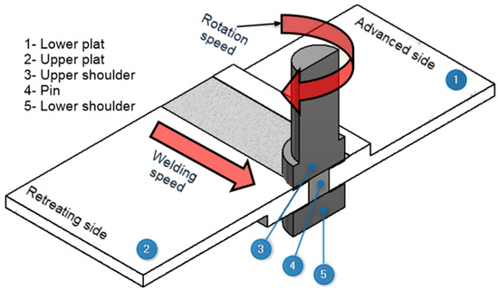
Figure 1.
Schematic of the bobbin too friction stir welding (BT-FSW) process.
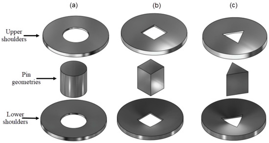
Figure 2.
3D drawings of the main BT-FSW tool parts that in contact with the workpieces during welding for three different pin geometries considered in the study: (a) Cylindrical pin, (b) square pin, and (c) triangular pin.
The heat generated during FSW process has two main sources as reported in the literature [1,10,14]. One is due to friction between the contact surfaces and the workpieces (sliding condition) and the second is due to severe plastic deformation taking place (sticking condition). The contribution of each is affected by the FSW parameters applied during the FSW process and also the materials to be welded [10]. The following expressions in Equations (2)–(4) consider both heat generation sources during BT- FSW and their effect on each other.
where f and d represent heat generated by friction and deformation, respectively, and δ represent the extent of slip between the tool and the workpiece.
Previous studies [10,22] reported that when δ = 0, the full sliding condition is applied, and the heat is generated only by friction. Whereas, if δ = 1, the full sticking condition is applied and then the heat is generated only by plastic deformation, according to, .
As per the reported data, the value of δ is typically very small [4,23]. For example, Heurtier et al. [4] estimated this value to be 0.1. Furthermore, Schmidt [23] and Hamilton [24] concluded that, in the presence of a low sticking condition, the frictional shear stress value is likely to be equal to the yield shear stress value of the material, so that Equations (2)–(4) can be modified as the following:
The general equations of frictional and deformation heat generation at different portions of BT (Figure 3) depend on the angular velocity (ω) and the applied torque (M), are reported by [8,10,19]:
where is frictional shear stress.
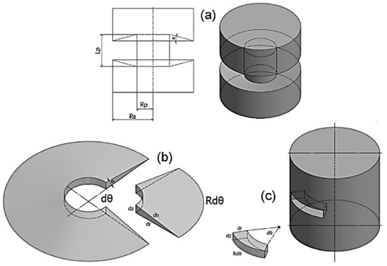
Figure 3.
(a) Schematic and isometric drawings of the used BT-FSW with cylindrical pin, (b) contact surface of upper or lower shoulder, and (c) cylindrical pin contact surface [21].
The generated heat by sliding is related to the contact shear stress [19,25] and it is given by Equation (9):
where (p) is the pressure and (μ) is the friction coefficient.
Previous works [8,10,22,24,26] indicated that the coefficient of friction (μ) decreases with the increase of temperature at the interface contact between the tool and workpiece and the μ value varies between 0.4 and 0.5 depending on the friction stirring variables. However, if heat generation exceeds the values of 2000 J/mm and 3000 J/mm, the μ values are 0.45 and 0.4, respectively. The μ value can be computed by:
In the current study, the static friction coefficient is considered as 0.45. Both the rotational speed as well as the rotational speed reference are taken as 400 rpm. Furthermore, the pin radius (Rs) and shoulder radius (Rm) values are taken as 0.4.
During the BT-FSW process, the gap between the two shoulders is exactly equivalent to the thickness of workpiece, Moreover, the pressure (p) acting on the BT shoulders results from the thermal expansion of the workpiece. With the beginning of the BT-FSW process, the welding temperature starts to increase. At a certain value of temperature, the thickness of workpiece also increases causing a pressure force (P) in Z direction on the BT shoulders. The value of p increases with increasing the ratio of Rs/Ts to reach the value of the temperature dependent yield stress σy.t of materials. The temperature dependence of the σy.t is given by [25,27]:
where is the yield stress, Tm is the solidus temperature is, and is the room temperature.
4. Heat Generation for BT-FSW with Cylindrical Pin
4.1. Heat Generation by BT-FSW at Shoulders
The friction heat generated at upper concave and lower concave shoulder is presented by:
where R, dθ, and dh are dimensions of infinitesimal elements of upper shoulder.
Integration of Equation (13) gives the heat generation at upper shoulder surface.
For BT-FSW, both the heat generated at the lower and the upper shoulders are the same and they are given by:
where Rus and Rls are radii of upper and lower shoulder, respectively.
The summation of heat generated at both shoulders () can be given by:
4.2. Heat Generation by BT-FSW at Cylindrical Pin Surface
The dimensions of bobbin tool and infinitesimal element for cylindrical pin surface are presented in Figure 2b and Figure 3. The frictional heat generation at infinitesimal elements for pin surface is given by:
The integration of Equation (20) determines the heat generation of the pin surface
Using Equations (16) and (18), the total heat generation for BT-FSW with concave shoulders and cylindrical pin is given as:
Based on Equations (19) and (23), the heat generation for concave shoulders can be calculated by:
For pin, the portion of heat generation given by:
For BT-FSW with concave shoulder, the energy per unite length is given by:
For flat shoulders (α = 0), the heat generated is given by:
The portion of heat generation with shoulders is given by:
For pin, the portion of heat generation given by:
The energy per unite length for BT-FSW with flat shoulders is computed by:
5. Heat Generation Model for BT-FSW with Square (Sq) Pin
5.1. Heat Generation in BT-FSW from Concave Shoulders
Figure 4 shows a schematic drawing of the FSW bobbin tool with square pin.
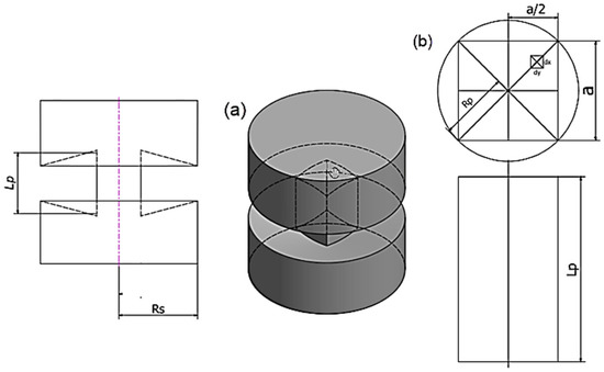
Figure 4.
(a) schematic drawing of BT-FSW with square pin, (b) contact surfaces of square pin.
The general equation of BT-FSW heat generation is given by Equation (1) and the upper shoulder heat generation is given by:
The generated heat by the lower shoulder is the same at the upper concave shoulder when . The sum of heat generated at both shoulders will let be used and given by:
5.2. Heat Generation in BT-FSW from Sq Pin Surface
From Figure 3 heat generation of the Sq. pin surface in BT-FSW is given by:
The total for BT-FSW with Sq. pin and concave shoulders is given by:
The is given by:
The is given by:
The energy per unite length for BT-FSW with Sq. pin and concave shoulders is given by:
For BT-FSW with flat shoulder and Sq pin, the following equations apply:
6. Heat Generation for BT-FSW with Triangle (Tr) Pin
6.1. Heat Generation from BT-FSW from Concave shoulder
Figure 5 presents the BT-FSW with concave shoulder and Tr. pin geometry. The heat generation is given by:
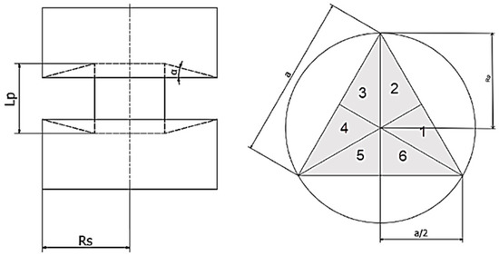
Figure 5.
Schematic drawing of BT-FSW with triangle pin.
For BT-FSW with concave shoulders and Tr pin, when the following equations apply:
6.2. Heat Generation in BT-FSW from Tr Pin Surface
For Tr pin, the equations of heat generation are given by:
The total for BT-FSW with Tr pin and concave shoulders are given by:
For BT-FSW with and Tr pin, the following Equations , , and are given, respectively:
For BT-FSW with flat shoulder and Tr. pin, the following equations apply:
7. Results and Discussion
7.1. Model Results and Discussion
In the following section, examples for the results that can be obtained from the use of the above mathematical models will be presented for the cylindrical pin (Cy) bobbin tool friction stir welding heat generation model (given in Section 3). Figure 6a shows the effect of the main FSW parameters on the heat generation during BT-FSW using the cylindrical pin. The range of the parameters (tool rotation rate, rpm and tool travel speed, mm/min) are taken between 100 and 1000 rpm (mm/min). It can be observed that the heat generation per unit length (J/mm) increases by the increase of the tool rotation rate and by the decrease of the tool travel speed to reach a maximum value of 12 KJ/mm at 1000 rpm and 100 mm/min. The heat generation becomes minimum at 100 rpm and 1000 mm/min. The results obtained from the model is consistent with the experimental results obtained in the literature. For example, Threadgill et al. [1] reported that the heat input during BT-FSW of AA6082 at 350 rpm and 500 mm/min was about 3KJ/mm. Heat input reflected directly on the temperature of the workpiece during BT-FSW [28]. Figure 6b shows the effect of the friction coefficient (μ) taken from zero to 0.8 on the heat generation during BT-FSW of aluminum at different FSW parameters. It can be observed that the heat generation increases by the increase of the friction coefficient up to 0.8. This clearly indicates the effect of the friction coefficient for the generation of the enough heat to accomplish the welding process. Colligan and Mishra [14] reported that, for modelling of heat input, a critical input required is the coefficient of friction during the friction stir process. They reported the values of coefficient of friction range from 0.3 to 1.3 for aluminum alloy AA2195.
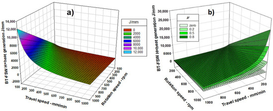
Figure 6.
(a) Effect of rotation and travel speeds on BT-FSW heat generation, (b) effect of friction coefficient (μ) on BT-FSW heat generation [21].
The dimensions of the tool are very important parameters in the heat generation as they represent the surfaces in contact with workpiece during FSW. Figure 7a shows the effect of tool shoulder dimension on the heat generation at a constant rotation rate of 600rpm and a constant travel speed of 600 mm/min. It can be observed that the heat generation increases by the increase of the shoulder diameter. As the shoulder diameter increases from 0 (pin only) to 20 mm, the heat generated increased from less than 200 J/mm to about 2300 J/mm. Figure 7b shows the effect of pin diameter on the heat generation during BT-FSW at a constant rotation rate of 600 rpm and a constant travel speed of 600 mm/min. Although the effect of the pin diameter is not as significant as the shoulder, an increase in the heat generation can still be observed by the increase of the pin diameter. When the pin diameter increases from 0 to 8 mm, the heat generated increased from about 540 J/mm to about 650 J/mm. This indicates the importance of tool dimensions’ optimization for the achievement of successful joints free from any defects.
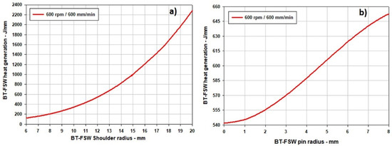
Figure 7.
(a) Effect of BT-FSW shoulder radius on BT-FSW heat generation. (b) Effects of BT-FSW pin radius on the heat generation [21].
The reported optimum dimensions for the FSW tool expressed in terms of the ratio between tool shoulder and the tool pin ranges between 2.5: 1 and 3:1 [20]. Although the tool dimension depends on the thickness of the welded material, systematic studies for the relation between pin radius and the material thickness are rarely investigated [29]. The pin diameter should be large enough to withstand the welding forces and small enough to allow stirring of material. The tool pin length depends on the workpiece thickness. Figure 8 shows the effect of the welded material thickness on the BT-FSW heat generation. The BT-FSW pin length equals the thickness of workpiece, and pin to shoulder radius is 1:2.5, and the pin radius is about 0.8 of the workpiece thickness. Clearly it can be observed that the heat generation increases significantly by the increase of the material thickness and this is mainly due to the increase in the surface area of contact between the tool and the workpiece. The suitable methodology to reduce or control the heat input in case of thick section materials FSW is to control or reduce the FSW parameters, such that increasing the welding speed and reducing the rotation rates [30,31,32,33,34,35,36,37,38,39,40,41,42].
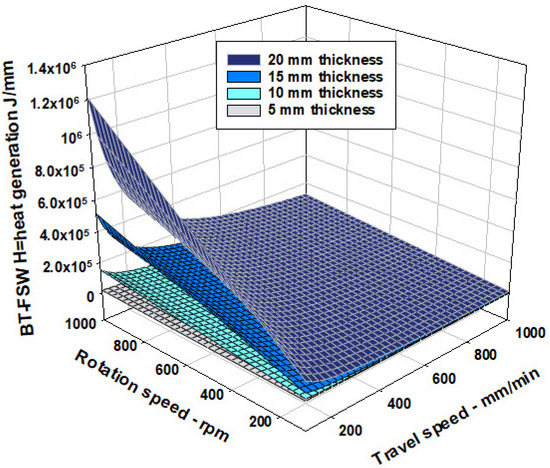
Figure 8.
Effect of different workpiece thickness on the BT-FSW heat generation.
The shoulder features also affect the heat generation due to their effect on the contact area between the shoulders and the workpiece. Figure 9 shows the effect of the shoulder concave angle on the BT-FSW heat generation with different tool rotation rates. Four degrees of concavity are involved 0° (Flat shoulder), 3°, 6°, and 9°. It can be observed that at a constant angle and by increasing the tool rotation rate, the heat generation linearly increased. By increasing the shoulder concave angle, the heat generation shifted up towards the high heat energy values. This can be attributed to the increase in the contact surface between the shoulder and the welded material.
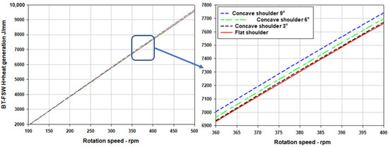
Figure 9.
Effect of concave shoulder angle on the total heat generation.
7.2. Model Validation
For the model validation, BT-FSW of 10-mm-thick aluminum alloy AA1050 was conducted using three bobbin tools with the description given in Table 1. It is important to have a relationship between the heat input and the welding temperature during BT-FSW of aluminum. For this purpose, the mathematical models used to calculate the welding temperatures (Tw) with their corresponding heat input took into account the three different tool geometries at a constant rotation rate of 600 rpm with five different welding speeds of 200, 400, 600, 800, and 1000 mm/min. The obtained 15 points for the welding temperature expressed in terms of relative temperature to the solidus temperature (Tw/Tm) of the alloy AA1050 (660 °C) and their corresponding heat inputs are plotted with a nonlinear regression curve and presented in Figure 10. The multiple correlation coefficient, R is 0.964, the coefficient of determination, R2 is 0.929, and the standard error of the estimate, Sx, is 0.0198. The relationship between the Tw/Ts and the BT-FSW heat generation per unit length can be expressed by the following empirical equation:
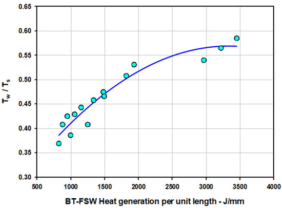
Figure 10.
Plot of the welding temperature expressed in terms of relative temperature to the solidus temperature (Tw/Ts) of the alloy AA1050 and their corresponding BT-FSW heat generation per unit length calculated at a constant rotation rate of 600 rpm and different welding speeds of 200, 400, 600, 800, and 1000 mm/min for the three pin geometries.
Table 3 shows the BT-FSW parameters, calculated heat generation per unit length for the BT shoulders (QEl,c) and BT pins (QEl,c), and calculated peak temperatures (Tw) compared with that measured during BT-FSW of AA1050 carried out in the experimental work for the models validation. Clearly it can be noted that the heat generated from the shoulder is significantly higher than that generated from pin for all types of pin geometries investigated. The percent of the shoulder heat generated in case of square, cylindrical, and triangular pins represent approximately 78%, 83%, and 88%, respectively. This increase of the shoulder contribution is a direct result for the increase of the shoulder surface area relative to the total tool surface area. It is worth mentioning here that as the pin surface contribution increases relative to the shoulder surface area, the total heat generated increases and consequently the welding temperature increases. This implies the significant effect of the pin geometry on the in case of BT-FSW. This effect will be more significant in case of the CT-FSW due to the existence of only one top shoulder. The effect of the pin surface area relative to the shoulders surface areas (Aps/A2s) on the amount of heat generated per unit length at the different welding speeds 200, 400, 600, 800, 1000 mm/min, and a constant rotation rate of 600 rpm for the three pin geometries is illustrated as bar chart in Figure 11.
Table 3.
Predicted heat energies per unit length generated from the BT parts, and predicted and measured welding temperatures during BT-FSW process.
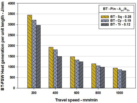
Figure 11.
The effect of the pin surface area relative to the shoulders surface areas (Aps/A2s) on the amount of heat generated per unit length at the different welding speeds 200, 400, 600, 800, 1000 mm/min, and a constant rotation rate of 600 rpm for the three pin geometries.
The temperature distribution along the lap joints during BT-FSW has been measured at several points using an infrared thermometer (Quicktemp 860-T3, Testo, temperature range from −30 °C to 900 °C). At the weld surface behind the tool, at the advancing side, and at the retreating side the average was taken to represent the welding temperature of each joint. The measured and calculated temperatures during 15 experiments are plotted against the welding speeds for the three bobbin tools and illustrated in Figure 12a,b. It can be observed that the welding temperature during BT-FSW of the AA1050 decreases with increasing the travel speed due to the reduction in the heat generation. In addition, it can be noted that the BT with the square pin generated the higher welding temperatures at all welding speeds and the triangular pin generated the lowest temperatures. This can be attributed to the high contribution from the heat generated from the pin with the largest surface area relative to the shoulders’ surfaces in case of the square pin that decreases by using cylindrical pin and decreases more by using the triangular pin. Furthermore, the calculated temperatures have a similar behavior. Figure 13 shows that there is a good agreement between the mathematical heat generation models calculated welding temperatures and that measured during BT-FSW experiments proving the validity of the developed models for predication of the heat generation as well as the welding temperatures. This agreement is almost perfect in case of the square and the cylindrical pins while there is a different between the calculated and measured using the triangular pin of about 6–8%. This can be attributed to the sticking of materials on the pin surface [13,43].
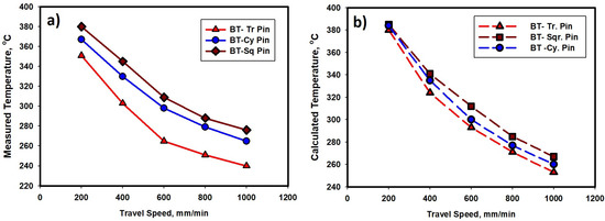
Figure 12.
(a) Measured temperatures and (b) model calculated temperatures vs. the travel speed during BT-FSW of AA1050 using different bobbin tool pin geometries.
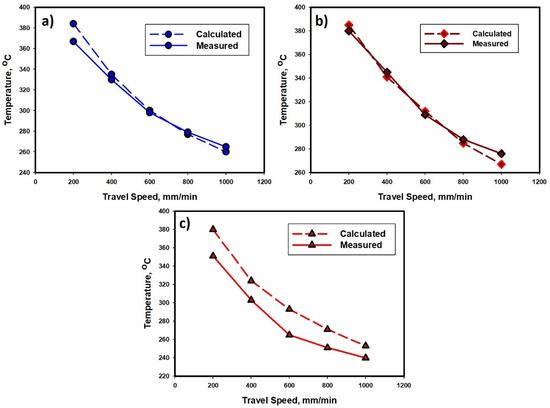
Figure 13.
Comparison of the measured welding temperatures and the models calculated temperatures during BT-FSW of AA1050 at different BT travel speeds using three pin geometries. (a) Cylindrical pin tool, (b) square pin tool, and (c) triangular pin tool.
8. Conclusions
Three mathematical models for heat generation during BT-FSW of AA1050 alloy using three tool pin geometries were developed and experimentally validated. Based on the obtained results, the following conclusions can be drawn:
- The developed models are very useful and valid for the predication of the heat generation and temperatures during BT-FSW of aluminum alloys. BT-FSW is one of the important FSW variants that has attractive advantages for industrial applications.
- The developed models considered the most common tool pin geometries and also validated and examined at a wide range of travel speeds for welding as an important parameter in controlling the weld quality and properties.
- The amount of heat generated during BT-FSW is directly proportional to the tool rotation rate, friction coefficient, welded pate thickness, shoulder radius, shoulder concave angle, and the tool pin surface area at constant shoulder surface areas. Meanwhile, it is inversely proportional to the tool travel speed.
- The BT with square pin resulted in higher heat generation (3451 J/mm at 200 mm/min and 875 J/mm at 1000 mm/min) and consequently higher welding temperatures (384 °C at 200 mm/min and 260 °C at 1000 mm/min) relative to the other two pins. The triangular pin generated the lowest heat generation (2965 J/mm at 200 mm/min and 820 J/mm at 1000 mm/min) and temperatures (380 °C at 200 mm/min and 254 °C at 1000 mm/min). This implies that as the pin surface contribution increases relative to the shoulder surface area, the total heat generated increases and consequently the welding temperature increases.
- The obtained welding temperatures from the models and that measured during BT-FSW are in good agreement at all the investigated welding speeds especially in the case of the square and cylindrical pins, proving the validity of the developed models for the predication of the heat generation as well as the welding temperatures. This will allow proper designing of the BT-FSW parameters and avoiding the conditions that can deteriorate the joint quality and properties.
Author Contributions
Data curation, M.M.Z.A., M.I.A.H., M.M.E.-S.S., and A.E.-N.; formal analysis, M.M.Z.A., N.J., and M.M.E.-S.S., and B.A.; investigation, M.M.Z.A., M.M.E.-S.S., and M.I.A.H.; methodology, M.M.Z.A., M.M.E.-S.S. and N.J.; software, N.J.; and B.A. supervision, M.M.Z.A., A.E.-N., and M.M.E.-S.S.; visualization, N.J. and B.A.; writing—original draft, M.M.Z.A. and M.I.A.H.; writing—review and editing, M.M.Z.A., M.I.A.H., B.A., and M.M.E.-S.S. All authors have read and agreed to the published version of the manuscript.
Funding
This research received no external funding.
Institutional Review Board Statement
Not applicable.
Informed Consent Statement
Not applicable.
Data Availability Statement
The data presented in this study are available on request from the corresponding author. The data are not publicly available due to the extremely large size.
Conflicts of Interest
The authors declare no conflict of interest.
Nomenclature
| AA | Aluminium alloys |
| α | Angle of shoulder |
| ω | Angular velocity |
| M | Applied torque |
| dA | Area of the infinitesimal element, mm2 |
| BT | Bobbin tool |
| BT-FSW | Bobbin tool friction stir welding |
| CT-FSW | Conventional tool friction stir welding |
| cy | Cylindrical |
| d | Deformation |
| δ | Extent of slip between the tool and the workpiece |
| Fs | Flat shoulder |
| fr | Friction |
| μ | Friction coefficient |
| τs | Frictional shear stress, Mm2 |
| Qd | Heat generated by deformation |
| Qf | Heat generated by friction |
| Qls | Heat generated by lower shoulder |
| Qp | Heat generated by pin |
| Q2.s | Heat generated by two shoulder |
| Qus | Heat generated by upper shoulder |
| J | Joule |
| lss | Lower shoulder surface |
| Tm | Melting temperature. |
| mm | Millimetre |
| min | Minutes |
| PP | Pin profile |
| Aps | Pin surface area of bobbin tool |
| p | Pressure, GPa |
| Rls | Radius of lower shoulder |
| Rls | Radius of lower shoulder |
| Rp | Radius of pin |
| Rus | Radius of upper shoulder |
| rpm | Revolutions per minute |
| TR | Room temperature. |
| A2s | Shoulders surface areas of bobbin tool |
| Tm | Solidus temperature |
| sq | Square |
| μo | Static friction coefficient |
| φ | The extent of slip between the tool and the workpiece |
| Qt | Total heat generation |
| Ts | Travel speed, mm/min |
| tr | Triangle |
| Us | Upper shoulder |
| Uss | Upper shoulder surface |
| Tw | Welding temperature |
| Tw | Welding temperature |
| σy | Yield stress, MPa |
References
- Threadgill, P.L.; Ahmed, M.M.Z.; Martin, J.P.; Perrett, J.G.; Wynne, B.P. The Use of Bobbin Tools for Friction Stir Welding of Aluminium Alloys. Mater. Sci. Forum 2010, 638–642, 1179–1184. [Google Scholar] [CrossRef]
- Meilinger, A.; Torok, I. The Importance of Friction Stir Welding Tool. Prod. Process. Syst. 2013, 6, 10. [Google Scholar]
- Bastier, A.; Maitournam, M.H.; Dang Van, K.; Roger, F. Steady State Thermomechanical Modelling of Friction Stir Welding. Sci. Technol. Weld. Join. 2006, 11, 278–288. [Google Scholar] [CrossRef]
- Heurtier, P.; Jones, M.J.J.; Desrayaud, C.; Driver, J.H.H.; Montheillet, F.; Allehaux, D. Mechanical and Thermal Modelling of Friction Stir Welding. J. Mater. Process. Technol. 2006, 171, 348–357. [Google Scholar] [CrossRef]
- Essa, A.R.S.; Ahmed, M.M.Z.; Mohamed, A.Y.A.; El-Nikhaily, A.E. An Analytical Model of Heat Generation for Eccentric Cylindrical Pin in Friction Stir Welding. J. Mater. Res. Technol. 2016, 5, 234–240. [Google Scholar] [CrossRef]
- Quintana, K.J.; Silveira, J.L.L. Mechanistic Models and Experimental Analysis for the Torque in FSW Considering the Tool Geometry and the Process Velocities. J. Manuf. Process. 2017, 30, 406–417. [Google Scholar] [CrossRef]
- Stringham, B.J.; Nelson, T.W.; Sorensen, C.D. Non-Dimensional Modeling of the Effects of Weld Parameters on Peak Temperature and Cooling Rate in Friction Stir Welding. J. Mater. Process. Technol. 2018, 255, 816–830. [Google Scholar] [CrossRef]
- Durdanović, M.B.; Mijajlović, M.M.; Milčić, D.S.; Stamenković, D.S. Heat Generation during Friction Stir Welding Process. Tribol. Ind. 2009, 31, 8–14. [Google Scholar]
- Buglioni, L.; Tufaro, L.N.; Svoboda, H.G. Thermal Cycles and Residual Stresses in FSW of Aluminum Alloys: Experimental Measurements and Numerical Models. Procedia Mater. Sci. 2015, 9, 87–96. [Google Scholar] [CrossRef]
- Nandan, R.; Roy, G.G.; Lienert, T.J.; Debroy, T. Three-Dimensional Heat and Material Flow during Friction Stir Welding of Mild Steel. Acta Mater. 2007, 55, 883–895. [Google Scholar] [CrossRef]
- Hilgert, J.; Schmidt, H.N.B.; Santos, J.F.; Huber, N. Thermal Models for Bobbin Tool Friction Stir Welding. J. Mater. Process. Tech. 2011, 211, 197–204. [Google Scholar] [CrossRef]
- Mehta, M.; Reddy, G.M.; Rao, A.V.; De, A. Numerical Modeling of Friction Stir Welding Using the Tools with Polygonal Pins. Def. Technol. 2015, 11, 229–236. [Google Scholar] [CrossRef]
- Mehta, K.P.; Badheka, V.J. Effects of Tool Pin Design on Formation of Defects in Dissimilar Friction Stir Welding. Procedia Technol. 2016, 23, 513–518. [Google Scholar] [CrossRef]
- Colligan, K.J.; Mishra, R.S. A Conceptual Model for the Process Variables Related to Heat Generation in Friction Stir Welding of Aluminum. Scr. Mater. 2008, 58, 327–331. [Google Scholar] [CrossRef]
- Alves, E.P.; Neto, F.P.; An, C.Y. Welding of AA1050 Aluminum with AISI 304 Stainless Steel by Rotary Friction Welding Process. J. Aerosp.Technol. Manag. São José dos Campos 2010, 2, 301–306. [Google Scholar] [CrossRef]
- Mhedhbi, M.; Khlif, M.; Bradai, C. Investigations of Microstructural and Mechanical Properties Evolution of AA1050 Alloy Sheets Deformed by Cold-Rolling Process and Heat Treatment Annealing. J. Mater. Environ. Sci. 2017, 8, 2967–2974. [Google Scholar]
- Msomi, V.; Mbana, N. Mechanical Properties of Friction Stir Welded AA1050-H14 and AA5083-H111 Joint: Sampling Aspect. Metals (Basel) 2020, 10, 214. [Google Scholar] [CrossRef]
- Silva, A.A.M.; Aldanondo, E.; Alvarez, P.; Arruti, E.; Echeverría, A. Friction Stir Spot Welding of AA 1050 Al Alloy and Hot Stamped Boron Steel (22MnB5). Sci. Technol. Weld. Join. 2010, 15, 682. [Google Scholar] [CrossRef]
- Mishra, R.S. Friction Stir Welding and Processing; Springer International Publishing Switzerland: Cham, Switzerland, 2014; ISBN 978-3-319-07042-1. [Google Scholar]
- Mishra, R.S. Friction Stir Welding and Processing; ASM International: Novelty, OH, USA, 2007; ISBN 978-0-87170-840-3. [Google Scholar]
- Habba, M.I.A.; Ahmed, M.M.Z.; Seleman, M.M.E.; El-nikhaily, A. An Analytical Model of Heat Generation for Friction Stir Welding Using Bobbin Tool Design General Equations of Heat Generation in BT-FSW Heat Generation for BT-FSW With. J. Pet. Min. Eng. 2018, 20, 1–5. [Google Scholar]
- Khairuddin, J.T. Development of Multi Component Loads, Torque and Temperature Measurement Device for Friction Stir Welding Process. Ph.D. Thesis, Universiti Sains Malaysia, Gelugor, Malaysia, 2013. [Google Scholar] [CrossRef]
- Schmidt, H.; Hattel, J.; Wert, J. An Analytical Model for the Heat Generation in Friction Stir Welding. Model. Simul. Mater. Sci. Eng. 2004, 12, 143–157. [Google Scholar] [CrossRef]
- Hamilton, C.; Dymek, S.; Sommers, A. A Thermal Model of Friction Stir Welding in Aluminum Alloys. Int. J. Mach. Tools Manuf. 2008, 48, 1120–1130. [Google Scholar] [CrossRef]
- Waheed, M.A.; Jaiyesimi, L.O.; Ismail, S.O.; Dairo, O.U. Analytical Investigations of the Effects of Tool Pin Profile and Process Parameters on the Peak Temperature in Friction Stir Welding. J. Appl. Comput. Mech. 2017, 3, 114–124. [Google Scholar] [CrossRef]
- El-Tayeb, N.S.M.; Low, K.O.; Brevern, P.V. On the Surface and Tribological Characteristics of Burnished Cylindrical Al-6061. Tribol. Int. 2009, 42, 320–326. [Google Scholar] [CrossRef]
- Hamilton, C.; Dymek, S.; Pietras, A. Numerical simulations for bobbin tool friction stir welding of aluminum 6082-T6. Arch. Metall. Mater. 2018, 63, 1115–1123. [Google Scholar] [CrossRef]
- Entringer, J.; Reimann, M.; Norman, A.; Jorge, F. Influence of Cu/Li Ratio on the Microstructure Evolution of Bobbin-Tool Friction Stir Welded Al–Cu–Li Alloys. Integr. Med. Res. 2019, 8, 2031–2040. [Google Scholar] [CrossRef]
- Ahmed, M.M.Z.; Wynne, B.P.; Rainforth, W.M.; Addison, A.; Martin, J.P.; Threadgill, P.L. Effect of Tool Geometry and Heat Input on the Hardness, Grain Structure, and Crystallographic Texture of Thick-Section Friction Stir-Welded Aluminium. Metall. Mater. Trans. A Phys. Metall. Mater. Sci. 2019, 50, 271–284. [Google Scholar] [CrossRef]
- Ahmed, M.M.Z.; Wynne, B.P.; El-Sayed Seleman, M.M.; Rainforth, W.M. A Comparison of Crystallographic Texture and Grain Structure Development in Aluminum Generated by Friction Stir Welding and High Strain Torsion. Mater. Des. 2016, 103, 259–267. [Google Scholar] [CrossRef]
- Ahmed, M.M.Z.; Wynne, B.P.; Martin, J.P. Effect of Friction Stir Welding Speed on Mechanical Properties and Microstructure of Nickel Based Super Alloy Inconel 718. Sci. Technol. Weld. Join. 2013, 18, 680–687. [Google Scholar] [CrossRef]
- Ahmed, M.M.Z.; Wynne, B.P.; Rainforth, W.M.; Threadgill, P.L. Quantifying Crystallographic Texture in the Probe-Dominated Region of Thick-Section Friction-Stir-Welded Aluminium. Scr. Mater. 2008, 59, 507–510. [Google Scholar] [CrossRef]
- Ahmed, M.M.Z.; Ataya, S.; El-Sayed Seleman, M.M.; Ammar, H.R.; Ahmed, E. Friction Stir Welding of Similar and Dissimilar AA7075 and AA5083. J. Mater. Process. Technol. 2017, 242, 77–91. [Google Scholar] [CrossRef]
- Ahmed, M.M.Z.; Wynne, B.P.; Rainforth, W.M.; Threadgill, P.L. Microstructure, Crystallographic Texture and Mechanical Properties of Friction Stir Welded AA2017A. Mater. Charact. 2012, 64, 107–117. [Google Scholar] [CrossRef]
- Ahmed, M.M.Z.; Wynne, B.P.; Rainforth, W.M.; Threadgill, P.L. Through-Thickness Crystallographic Texture of Stationary Shoulder Friction Stir Welded Aluminium. Scr. Mater. 2011, 64, 45–48. [Google Scholar] [CrossRef]
- Zayed, E.M.; El-Tayeb, N.S.M.; Ahmed, M.M.Z.; Rashad, R.M. Development and Characterization of AA5083 Reinforced with SiC and Al2O3 Particles by Friction Stir Processing; Springer: Cham, Switzerland, 2019; Volume 92. [Google Scholar]
- Refat, M.; Elashery, A.; Toschi, S.; Ahmed, M.M.Z.; Morri, A.; El-Mahallawi, I.; Ceschini, L. Microstructure, Hardness and Impact Toughness of Heat-Treated Nanodispersed Surface and Friction Stir-Processed Aluminum Alloy AA7075. J. Mater. Eng. Perform. 2016, 25, 5087–5101. [Google Scholar] [CrossRef]
- Mohamed, M.; Ahmed, Z.; Ataya, S.; Seleman, M.M.E.; Allam, T. Grain Structure, Crystallographic Texture, and Hardening Behavior of Dissimilar Friction Stir Welded AA5083-O And. Metals (Basel) 2021, 11, 181. [Google Scholar]
- Ahmed, M.M.Z.; Seleman, M.M.E.; Zidan, Z.A.; Ramadan, R.M.; Ataya, S.; Alsaleh, N.A. Microstructure and Mechanical Properties of Dissimilar Friction Stir Welded AA2024-T4/AA7075-T6 T-Butt Joints. Metals (Basel) 2021, 11, 128. [Google Scholar] [CrossRef]
- Ahmed, M.M.Z.; Barakat, W.S.; Mohamed, A.Y.A.; Alsaleh, N.A. The Development of WC-Based Composite Tools for Friction Stir Welding of High-Softening-Temperature Materials. Metals (Basel) 2021, 11, 285. [Google Scholar] [CrossRef]
- Ahmed, M.M.Z.; Ataya, S.; Seleman, M.M.E.; Mahdy, A.M.A.; Alsaleh, N.A.; Ahmed, E. Heat Input and Mechanical Properties Investigation of Friction Stir Welded AA5083/AA5754 and AA5083/AA7020. Metals (Basel) 2021, 11, 68. [Google Scholar] [CrossRef]
- El Rayes, M.M.; Soliman, M.S.; Abbas, A.T.; Pimenov, D.Y.; Erdakov, I.N.; Abdel-mawla, M.M. Effect of Feed Rate in FSW on the Mechanical and Microstructural Properties of AA5754 Joints. Adv. Mater. Sci. Eng. 2019, 2019, 4156176. [Google Scholar] [CrossRef]
- Mehta, M.; De, A.; DebRoy, T. Material Adhesion and Stresses on Friction Stir Welding Tool Pins. Sci. Technol. Weld. Join. 2014, 19, 534–540. [Google Scholar] [CrossRef]


Publisher’s Note: MDPI stays neutral with regard to jurisdictional claims in published maps and institutional affiliations. |
© 2021 by the authors. Licensee MDPI, Basel, Switzerland. This article is an open access article distributed under the terms and conditions of the Creative Commons Attribution (CC BY) license (http://creativecommons.org/licenses/by/4.0/).