
Computational Fluid Dynamics (CFD) Simulation of Inclusion Motion under Interfacial Tension in a Flash Welding Process

 ,
, 


Abstract
1. Introduction
2. Experiment
3. Numerical Modeling
3.1. The Governing Equation
3.2. Numerical Details
4. Results and Discussion
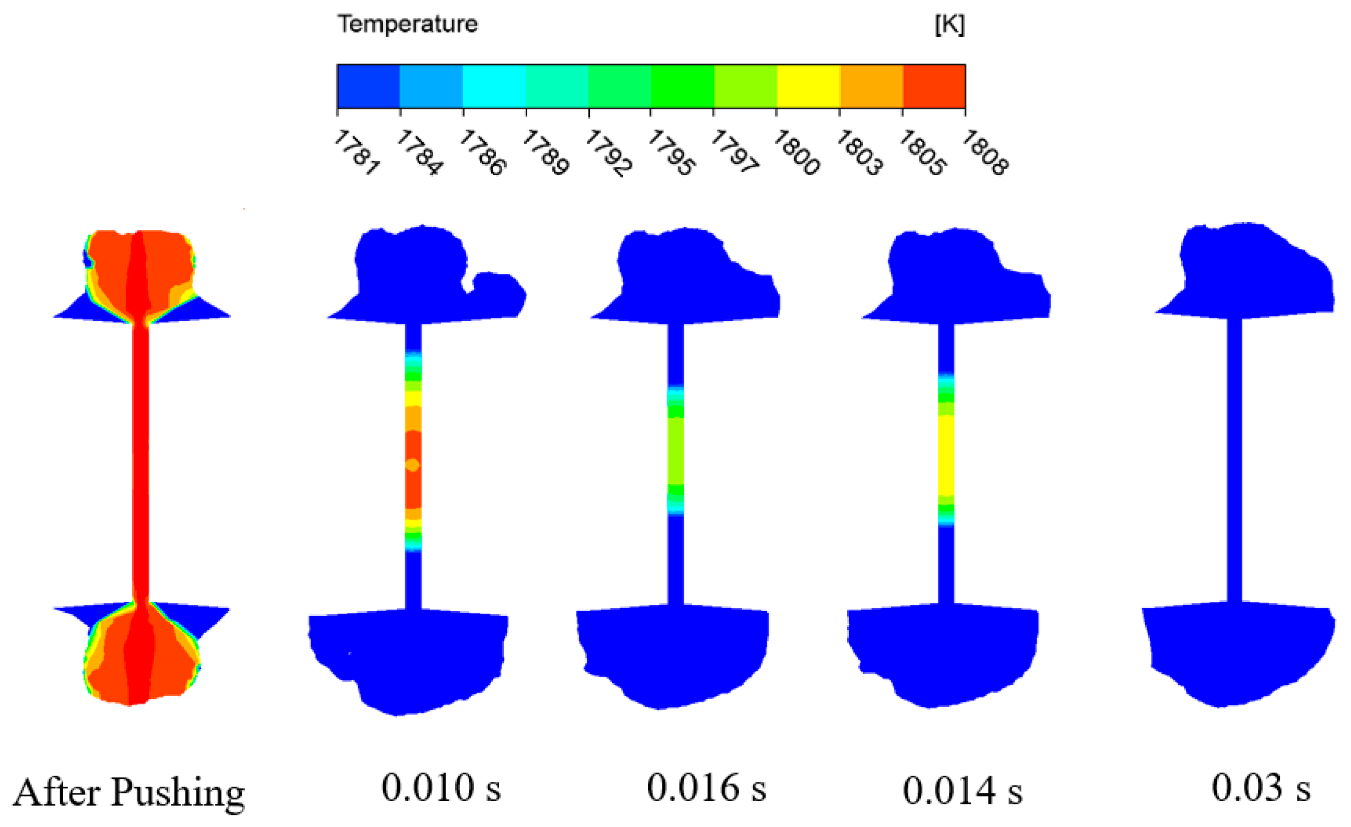
4.1. Upsetting Process
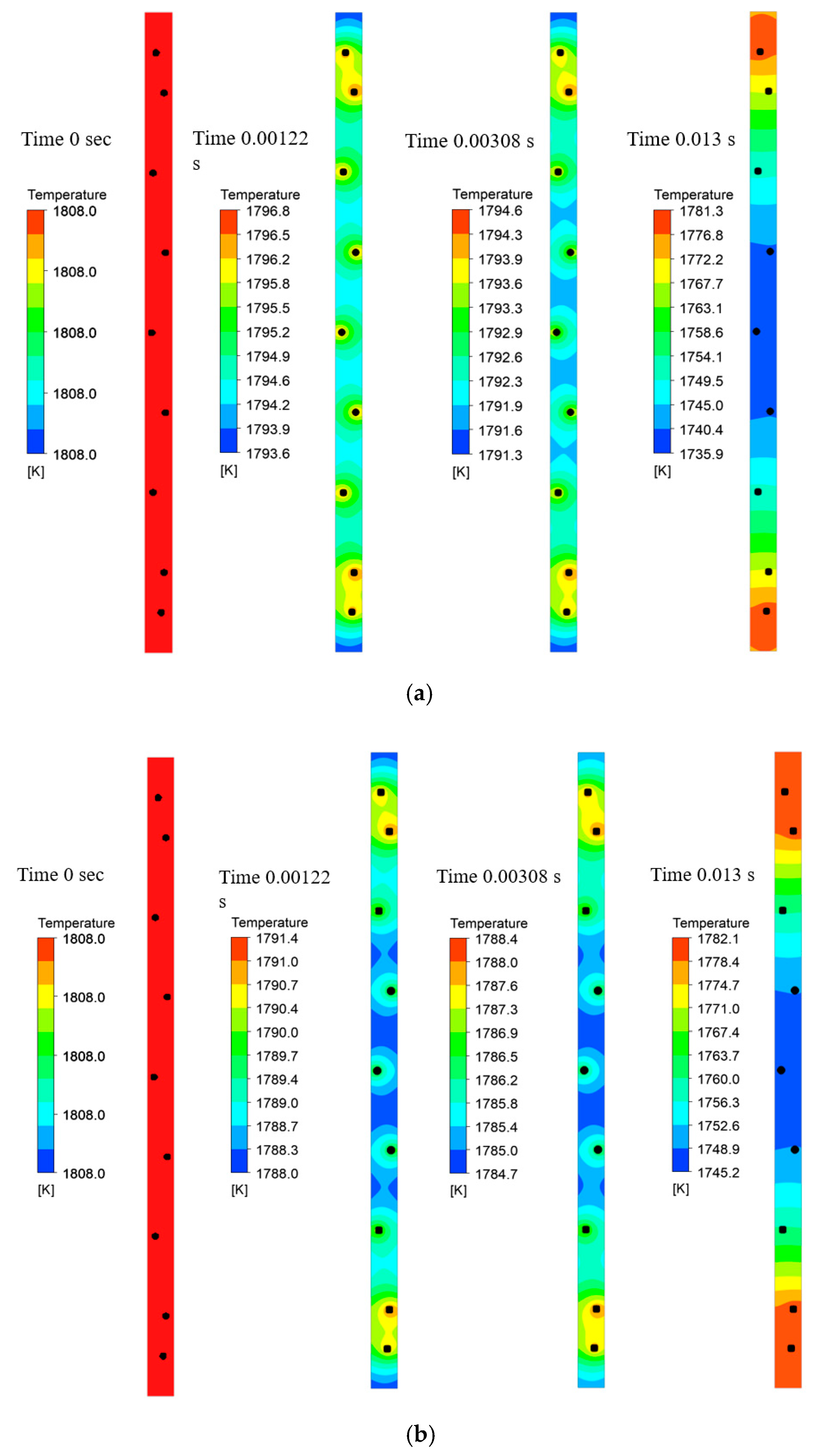
4.2. Inclusion Size
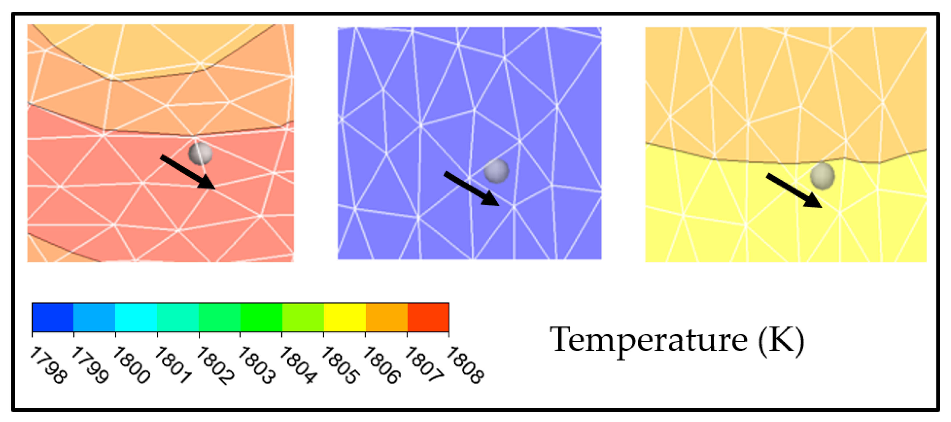
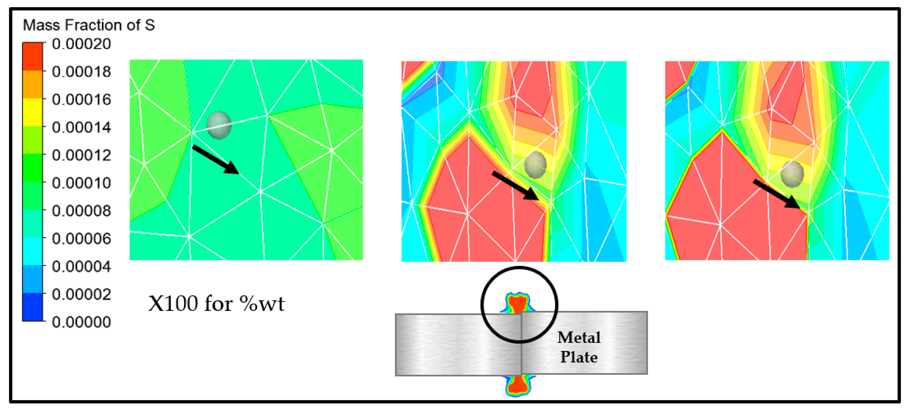
4.3. Solidification
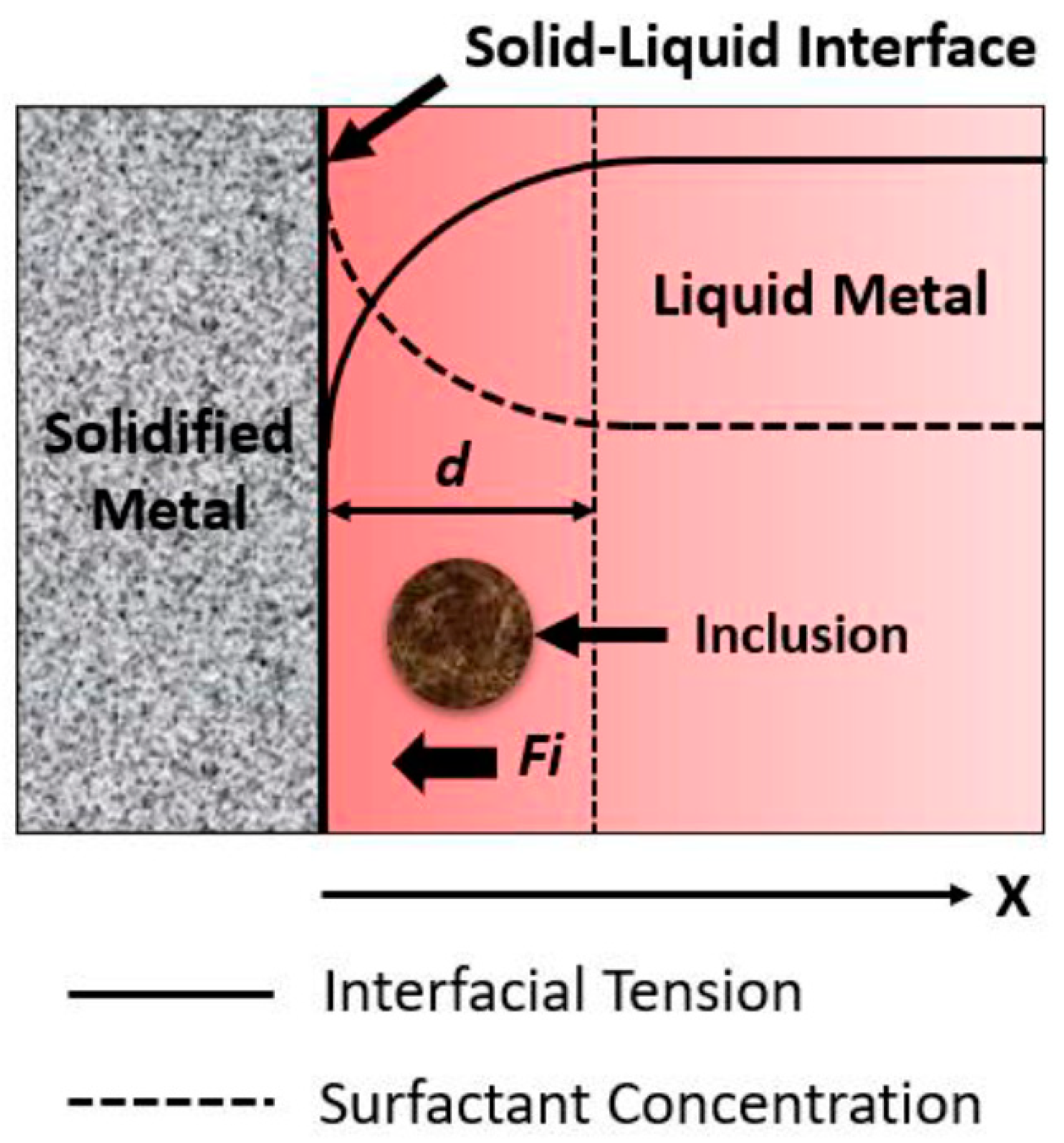
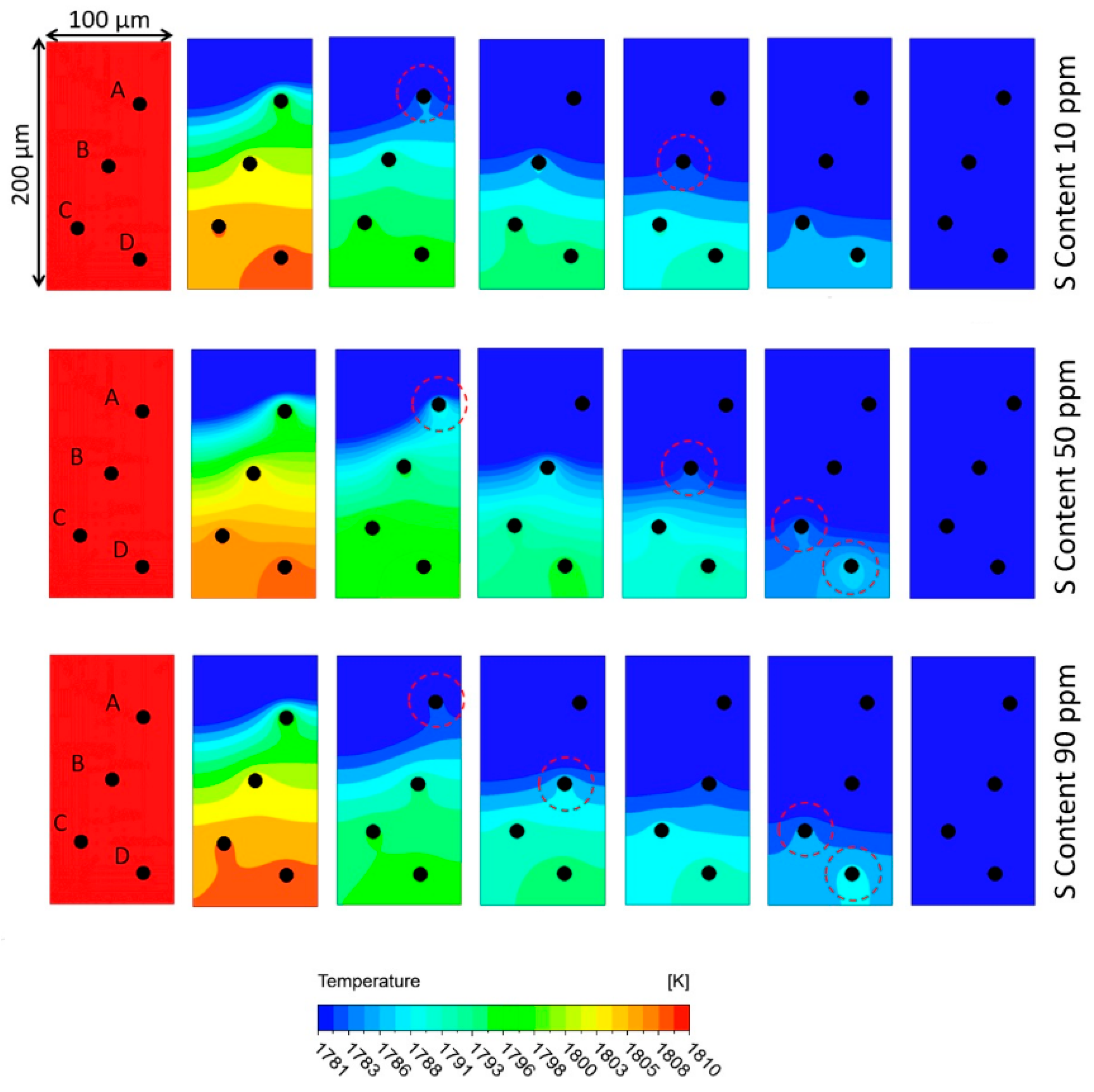
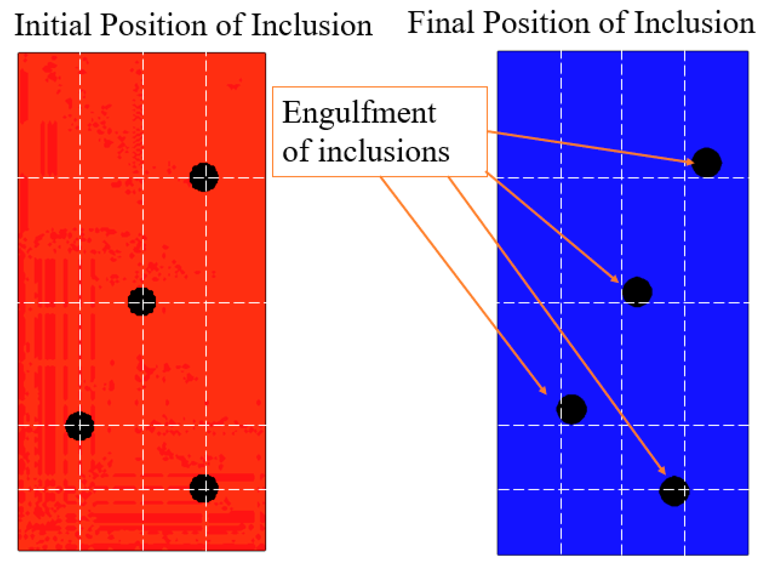
4.4. Pushing and Engulfment of Inclusions
5. Conclusions
Author Contributions
Funding
Data Availability Statement
Acknowledgments
Conflicts of Interest
References
- Kim, D.C.; So, W.J.; Kang, M.J. Effect of flash butt welding parameters on weld quality of mooring chain. Arch. Mater. Sci. Eng. 2009, 38, 112–117. [Google Scholar]
- Wang, W.; Shi, Y.; Lei, Y.; Tian, Z. FEM simulation on microstructure of DC flash butt welding for an ultra-fine grain steel. J. Mater. Process. Technol. 2005, 161, 497–503. [Google Scholar] [CrossRef]
- Ichiyama, Y.; Kodama, S. Flash-butt welding of high strength steels. Nippon Steel Tech. 2007, 95, 81–87. [Google Scholar]
- Turner, R.P.; Perumal, B.; Lu, Y.; Ward, R.M.; Basoalto, H.C.; Brooks, J.W. Modeling of the Heat-Affected and Thermomechanically Affected Zones in a Ti-6Al-4V Inertia Friction Weld. Metall. Mater. Trans. B 2019, 50, 1000–1011. [Google Scholar] [CrossRef]
- Kitano, H. Numeric Law Discovery and Knowledge Extraction from Welding Phenomena Using Machine Learning Technique. Mater. Jpn. 2019, 58, 449–452. [Google Scholar] [CrossRef]
- Chen, Z.; Nash, P.; Zhang, Y. Correlation of Cooling Rate, Microstructure and Hardness of S34MnV Steel. Metall. Mater. Trans. B 2019, 50, 1718–1728. [Google Scholar] [CrossRef]
- Šebestová, H.; Horník, P.; Mrňa, L.; Doležal, P.; Mikmeková, E. The Effect of Arc Current on Microstructure and Mechanical Properties of Hybrid LasTIG Welds of High-Strength Low-Alloy Steels. Metall. Mater. Trans. B 2018, 49, 3559–3569. [Google Scholar] [CrossRef]
- Matsui, Y.; Iizuka, Y.; Okabe, T.; Inoue, T. Evaluation method for low temperature toughness of weld seam of HFW pipe based on the distribution of scattered type penetrator. ISIJ Int. 2017, 57, 2010–2015. [Google Scholar] [CrossRef]
- Barrick, E.J.; DuPont, J.N. Mechanical properties and microstructural characterization of simulated heat-affected zones in 10 wt pct Ni steel. Mater. Sci. Eng. A 2019, 748, 189–204. [Google Scholar] [CrossRef]
- Moeini, G.; Ramazani, A.; Hildebrand, J.; Roessler, C.; Koenke, C. Study of the effect of microstructural variation on the low cycle fatigue behavior of laser welded DP600 steel: Simulation and experimental validation. Mater. Sci. Eng. A 2018, 730, 232–243. [Google Scholar] [CrossRef]
- Çetinkaya, C.; Arabaci, U. Flash butt welding application on 16MnCr5 chain steel and investigations of mechanical properties. Mater. Des. 2006, 27, 1187–1195. [Google Scholar] [CrossRef]
- Bhattacharyya, S.; Adhikary, M.; Das, M.B.; Sarkar, S. Failure analysis of cracking in wheel rims—Material and manufacturing aspects. Eng. Fail. Anal. 2008, 15, 547–554. [Google Scholar] [CrossRef]
- Lina, S.; Deng, Y.-L.; Tanga, J.-G.; Deng, S.-H.; Linc, H.-Q.; Ye, L.-Y.; Zhang, X.-M. Microstructures and fatigue behavior of metal-inert-gas-welded joints for extruded Al-Mg-Si alloy. Mater. Sci. Eng. A 2019, 745, 63–73. [Google Scholar] [CrossRef]
- Lu, P.; Xu, Z.; Jiang, K.; Ma, F.; Shu, Y. Influence of flash butt welding parameters on microstructure and mechanical properties of HSLA 590CL welded joints in wheel rims. J. Mater. Res. 2017, 32, 831–842. [Google Scholar] [CrossRef]
- Shajan, N.; Arora, K.S.; Sharma, V.; Shome, M. Effect of upset pressure on texture evolution and its correlation to toughness in flash butt joints. Sci. Technol. Weld. Join. 2018, 23, 434–440. [Google Scholar] [CrossRef]
- Shajan, N.; Arora, K.S.; Asati, B.; Sharma, V.; Shome, M. Effects of Post-Weld Heat Treatment on the Microstructure and Toughness of Flash Butt Welded High-Strength Low-Alloy Steel. Metall. Mater. Trans. A 2018, 49, 1276–1286. [Google Scholar] [CrossRef]
- Joo, M.S.; Noh, K.-M.; Kim, W.-K.; Bae, J.-H.; Lee, C.-S. A Study of Metallurgical Factors for Defect Formation in Electric Resistance Welded API Steel Pipes. Metall. Mater. Trans. E 2015, 2, 119–130. [Google Scholar] [CrossRef]
- Yu, X.; Feng, L.; Qin, S.; Zhang, Y.; He, Y. Fracture analysis of U71Mn rail flash-butt welding joint. Case Stud. Eng. Fail. Anal. 2015, 4, 20–25. [Google Scholar] [CrossRef]
- Ichiyama, Y.; Saito, T. Factors affecting flash weldability in high strength steel—A study on toughness improvement of flash welded joints in high strength steel. Weld. Int. 2004, 18, 436–443. [Google Scholar] [CrossRef]
- Lu, P.; Xu, Z.; Shu, Y.; Ma, F. Microstructure and Failure Analysis of Flash Butt Welded HSLA 590CL Steel Joints in Wheel Rims. JOM 2017, 69, 135–143. [Google Scholar] [CrossRef]
- Taka, T.T.; Kunishige, K.; Yamauchi, N.; Nagao, N. Hot-rolled Steel Sheet with Excellent Flash Weldability for Automotive Wheel Rim Use. ISIJ Int. 1989, 29, 503–510. [Google Scholar] [CrossRef][Green Version]
- Godefroid, L.B.; Faria, G.L.; Cândido, L.C.; Viana, T.G. Failure analysis of recurrent cases of fatigue fracture in flash butt welded rails. Eng. Fail. Anal. 2015, 58, 407–416. [Google Scholar] [CrossRef]
- Saito, T.; Ichiyama, Y. Correlation between welding phenomena and weld defects before and after the start of upsetting: Welding phenomena and process control in flash welding of steel sheet (2nd Report). Weld. Int. 1996, 10, 173–180. [Google Scholar] [CrossRef]
- Xi, C.; Sun, D.; Xuan, Z.; Wang, J.; Song, G. Microstructures and mechanical properties of flash butt welded high strength steel joints. Mater. Des. 2015, 96, 506–514. [Google Scholar] [CrossRef]
- Ziemian, C.W.; Sharma, M.M.; Whaley, D.E. Effects of flashing and upset sequences on microstructure, hardness, and tensile properties of welded structural steel joints. Mater. Des. 2012, 33, 175–184. [Google Scholar] [CrossRef]
- Siddiqui, M.I.H.; Geleta, D.D.; Bae, G.; Lee, J. Numerical Modeling of the Inclusion Behavior during AC Flash Butt Welding. ISIJ Int. 2020, 60, 1–9. [Google Scholar] [CrossRef]
- Shibata, H.; Yin, H.; Yoshinaga, S.; Emi, T.; Suzuki, M. In Situ Observation of Engulfment and Pushing of Nonmetallic Inclusions in Steel Melt by Advancing Melt/Solid Interface. ISIJ Int. 1998, 38, 49–56. [Google Scholar] [CrossRef]
- Scheller, P.R.; Lee, J.; Yoshikwa, T.; Tanaka, T. Treatise on Process Metallurgy Volume 2: Process Phenomena. In Treatise on Process Metallurgy; Seetharaman, S., Ed.; Elsevier: Oxford, UK, 2013; Volume 2, pp. 119–139. [Google Scholar]
- Yin, H.; Emi, T. Marangoni flow at the gas/melt interface of steel. Metall. Mater. Trans. B 2003, 34, 483–493. [Google Scholar] [CrossRef]
- Wang, Z.; Mukai, K.; Lee, J. Behavior of fine bubbles in front of the solidifying interface. ISIJ Int. 1999, 39, 553–562. [Google Scholar] [CrossRef]
- Mukai, K.; Zeze, M. Motion of fine particles under interfacial tension gradient in relation to continuous casting process. Steel Res. 2003, 74, 131–138. [Google Scholar] [CrossRef]
- Matsushita, T.; Mukai, K.; Zeze, M. Correspondence between surface tension estimated by a surface thermodynamic model and number of bubbles in the vicinity of the surface of steel products in continuous casting process. ISIJ Int. 2013, 53, 18–26. [Google Scholar] [CrossRef]
- Hong, T.; Debroy, T.; Abu, S.S.B.; David, S.A. Modeling of inclusion growth and dissolution in the weld pool. Metall. Mater. Trans. B 2000, 31, 161–169. [Google Scholar] [CrossRef]
- Stachnik, M.; Jakubowski, M. Multiphase model of flow and separation phases in a whirlpool: Advanced simulation and phenomena visualization approach. J. Food Eng. 2020, 274, 109846. [Google Scholar] [CrossRef]
- Siddiqui, M.I.H.; Jha, P.K. Assessment of turbulence models for prediction of intermixed amount with free surface variation using CLSVOF method. ISIJ Int. 2014, 54, 2578–2587. [Google Scholar] [CrossRef]
- Jakubowski, M.; Wyczalkowski, W.; Poreda, A. Flow in a symmetrically filled whirlpool: CFD modelling and experimental study based on Particle Image Velocimetry (PIV). J. Food Eng. 2015, 145, 64–72. [Google Scholar] [CrossRef]
- Jeong, J.; Park, D.; Shim, S.; Na, H.; Bae, G.; Seo, S.-J.; Lee, J. Interfacial tension between SPFH590 microalloyed steel and alumina. Metall. Mater. Trans. B 2019, 51, 690–696. [Google Scholar] [CrossRef]
- ANSYS FLUENT Theory Guide 18.2; ANSYS Inc.: Canonsburg, PA, USA, 2017.
- Cho, D.W.; Na, S.J. Molten pool behaviors for second pass V-groove GMAW. Int. J. Heat Mass Transf. 2015, 88, 945–956. [Google Scholar] [CrossRef]
- Engh, T.A.; Simensen, C.J.; Wijk, O. Principles of Metal Refining; Oxford University Press: Oxford, UK, 1992. [Google Scholar]
- Sadeghian, B.; Taherizadeh, A.; Atapour, M. Simulation of weld morphology during friction stir welding of aluminum- stainless steel joint. J. Mater. Process. Technol. 2018, 259, 96–108. [Google Scholar] [CrossRef]
- Jeong, J.; Park, D.; Shim, S.; Na, H.; Bae, G.; Seo, S.-J.; Lee, J. Prediction of Behavior of Alumina Inclusion in Front of Solid–Liquid Interface in SPFH590 Steel. Metall. Mater. Trans. B Process Metall. Mater. Process. Sci. 2020, 51, 690–696. [Google Scholar] [CrossRef]


Publisher’s Note: MDPI stays neutral with regard to jurisdictional claims in published maps and institutional affiliations. |
© 2021 by the authors. Licensee MDPI, Basel, Switzerland. This article is an open access article distributed under the terms and conditions of the Creative Commons Attribution (CC BY) license (https://creativecommons.org/licenses/by/4.0/).
Share and Cite
Siddiqui, M.I.H.; Alshehri, H.; Orfi, J.; Ali, M.A.; Dobrotă, D. Computational Fluid Dynamics (CFD) Simulation of Inclusion Motion under Interfacial Tension in a Flash Welding Process. Metals 2021, 11, 1073. https://doi.org/10.3390/met11071073
Siddiqui MIH, Alshehri H, Orfi J, Ali MA, Dobrotă D. Computational Fluid Dynamics (CFD) Simulation of Inclusion Motion under Interfacial Tension in a Flash Welding Process. Metals. 2021; 11(7):1073. https://doi.org/10.3390/met11071073
Chicago/Turabian StyleSiddiqui, Md Irfanul Haque, Hassan Alshehri, Jamel Orfi, Masood Ashraf Ali, and Dan Dobrotă. 2021. "Computational Fluid Dynamics (CFD) Simulation of Inclusion Motion under Interfacial Tension in a Flash Welding Process" Metals 11, no. 7: 1073. https://doi.org/10.3390/met11071073
APA StyleSiddiqui, M. I. H., Alshehri, H., Orfi, J., Ali, M. A., & Dobrotă, D. (2021). Computational Fluid Dynamics (CFD) Simulation of Inclusion Motion under Interfacial Tension in a Flash Welding Process. Metals, 11(7), 1073. https://doi.org/10.3390/met11071073