Article

Increasing the Durability of Trimming Dies Used to Clean Anodes in the Aluminum Industry

by
Delia Gârleanu
1,
Claudia Borda
1,*,
Gabriel Gârleanu
1,*,
Cristina Modrogan
2,
Marius Dumitraș
1,
Dan Dobrotă
3,*,
Sever-Gabriel Racz
3 and
Loredana Cristina Dascălu
1
1
Department of Quality Engineering and Industrial Technologies, University POLITEHNICA of Bucharest, Splaiul Independentei No. 313, 999032 Bucharest, Romania
2
Department of Analytical Chemistry and Environmental Engineering, University POLITEHNICA of Bucharest, Splaiul Independentei No. 313, 999032 Bucharest, Romania
3
Department of Industrial Engineering and Management, Faculty of Engineering, University Lucian Blaga of Sibiu, Str. Emil Cioran Nr.4, 550025 Sibiu, Romania
*
Authors to whom correspondence should be addressed.
Metals 2021, 11(8), 1157; https://doi.org/10.3390/met11081157
Submission received: 13 June 2021 / Revised: 14 July 2021 / Accepted: 19 July 2021 / Published: 22 July 2021
(This article belongs to the Special Issue Design of Welded Steel Structures)

Abstract

:
Increasing the durability of trimming dies used to clean anodes is a very important goal in order to reduce the costs involved in obtaining aluminum. The research focused both on choosing an optimal material for the execution of trimming dies and on the application of technologies for plating active areas and, at the same time, on optimizing the geometric shape of the active area of the trimming die. In order to choose an optimal material from which to make the trimming dies, it was taken into account that they are usually made of X210Cr12 steel. In the stage of choosing an optimal material for the execution of the trimming dies, five steels were taken into account, namely: K105, K107, K110, K360, and K460. Analyses of the metallographic structure of the passage area were performed between the metal deposited by welding and the base material, demonstrating the fact that hot welding plating allows obtaining a more homogeneous metallographic structure compared to cold welding plating. The choice of new material was not a solution to increase the durability of the trimming die. Change in the trimming die geometry determined a reduction in deformations of about 13.8 times and of the equivalent stresses of about 7 times compared to those obtained in the case of the old trimming die. In addition, the durability of the trimming die with the new construction shape increases approximately three times compared to the trimming die with the old geometric shape. This demonstrates that the solution to increasing the durability of the trimming die is to adopt an optimal geometry of the active part at the expense of choosing an optimal material.

1. Introduction

The aluminum electrolytic industry is a very large energy-consuming industry and one of the largest consuming materials. The category of materials consumed in the technology of obtaining aluminum by electrolysis includes carbon anodes [1]. Aluminum electrolysis is a complex, nonlinear, and multivariate industrial control process. As a result, the problem of its optimization continues to arise [2].
In order to ensure the sustainable development of the aluminum industry, new strategies are needed to modernize existing production facilities, namely the use of new technological equipment capable of meeting existing standards in terms of environment, industrial safety, and efficiency. Thus, it is necessary to identify technical solutions for the conservation of materials and energy, and it is important to carry out studies aimed at identifying technological possibilities to reduce the consumption of materials and energy in the aluminum industry [3,4].
A particular problem concerns the durability of consumable carbon anodes. In this sense, one solution is the use of inert anodes in the Hall–Héroult electrolysis process, but this is still a goal that has only been partially achieved in the primary aluminum industry. The creation of a non-carbon anode has become increasingly important with increasing pressure on the aluminum industry to reduce greenhouse gas emissions [5,6].
Due to the difficulties of introducing new types of anodes in practice, carbon anodes are currently used in primary aluminum production. These types of anodes have rather low durability and must be changed at short intervals. A particular problem that arises when changing carbon anodes refers to the technological process of cleaning the support on which they are disposed by the materials that were used to fix them on the support. In this sense, in most cases, the fixing of the anodes on the support is performed by means of cast irons. Thus, the replacement of a carbon anode involves the removal of the cast iron layer to clean the anode support in order to mount a new anode.
In order to increase the productivity of the process of cleaning the anode supports, in practice, a series of tools have been designed to allow the removal of the cast iron layer. This process is quite complex, and, to increase productivity, a number of trimming dies have been created, which generally have low durability. Under these conditions, the question arises of identifying possibilities to increase the durability of these trimming dies. Given the above, the process of cleaning the anodes is similar to the process of cutting cast iron.
During the use of anodes, due to the heat released, the cast iron that fixes the carbon anode on the support undergoes a series of changes in properties. Thus, cast iron can change its hardness in the sense of increasing it, but also the metallographic structure, and all this negatively influences the process of crushing it. In addition, the thermal effect can cause the accumulation of residual stresses in cast iron that can generate certain cracks that can compromise the structure of the components and can lead to economic losses [7,8].
In the operations of grinding the castings, it was found that there is a big difference in the life of the tools used, depending on their structure, finding major differences between conditions for crushing compacted graphite (CGI) iron and spheroidal graphite iron (SGI) [9,10,11]. Thus, depending on the structure, the cast irons can be crushed with the help of tools with a certain geometry made of different materials [12].
Some studies recommend using polycrystalline cubic boron nitride (pcBN) for high-speed processing of cast iron [13,14,15], but this cannot be applied in the case of the trimming dies used to clean anode supports. In addition, in addition to the possibility of conducting experimental research on cast iron cutting processes, cutting simulation methods can be applied, such as the finite element method (FEM), which allows us to obtain information on the process of splinter formation, distribution voltages, temperature distribution [16,17,18,19].
Given the above, the main objective of the research was to identify the technological possibilities of making trimming die-type tools that are used to clean the support of carbon dioxide in the primary industry of aluminum in order to increase their durability. Thus, the research focused mainly on choosing an optimal material from which these tools can be made but also on identifying the possibilities of plating by welding the active parts of the trimming dies and establishing an optimal geometry for them. Under these conditions, the material usually used to make matrix was replaced with five other materials, and plating by welding was performed using two technologies: hot and cold, respectively. In addition, to optimize the geometry of the active part of the trimming dies, FEM was used, and thus, it was possible to make a trimming dies from a new material with an optimal geometry that allowed a substantial increase in its durability.

2. Materials and Methods

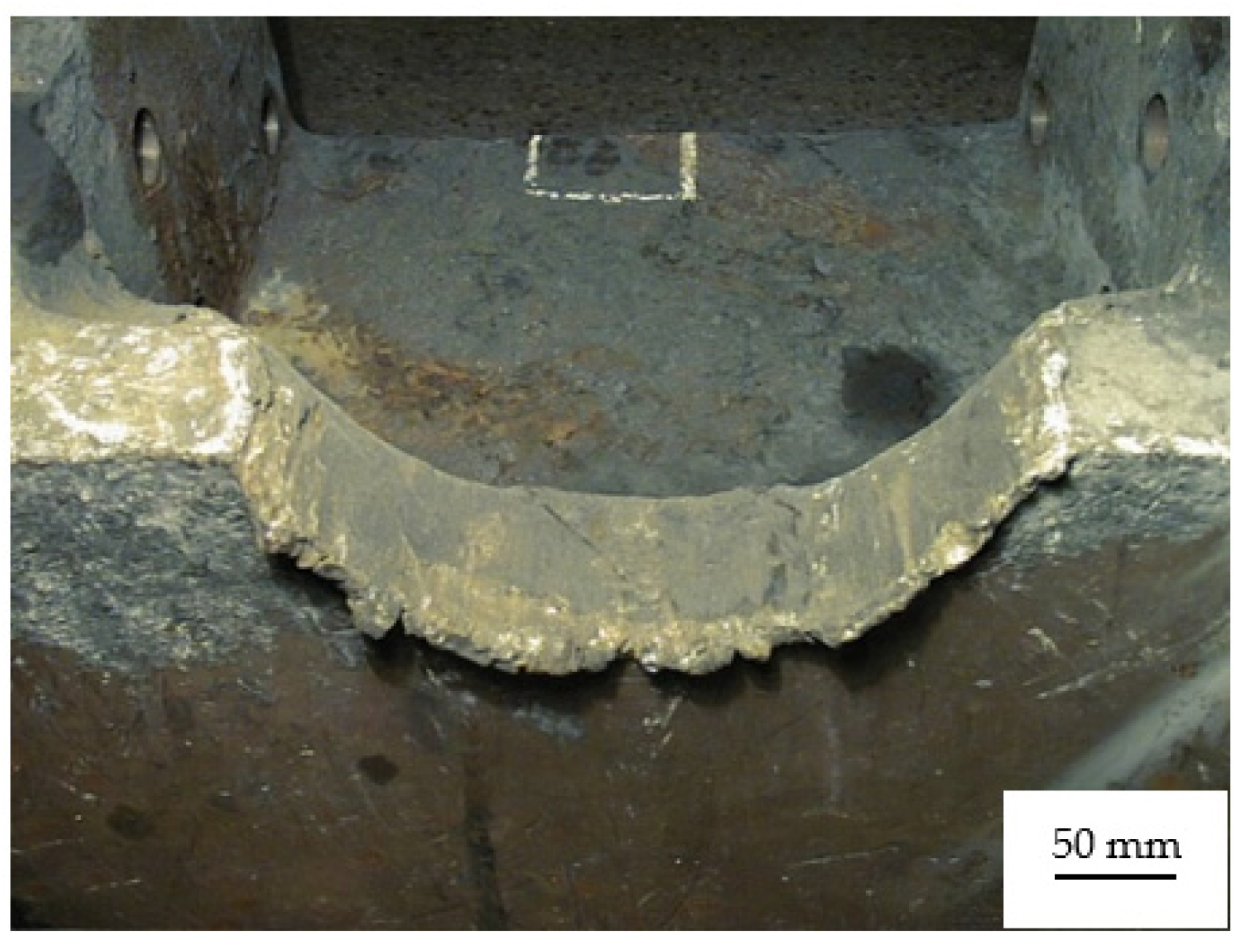
2.1. Characterization of Anodes Used in the Aluminum Industry

In the aluminum manufacturing industry, carbon electrodes are widely used in electrolysis tanks. In electrolysis installations, the anode (+) and the cathode (−) are parts or assemblies made of different materials and with a process-specific geometric configuration.
During the research, the anode was analyzed, which has a shape composed of an aluminum bar, the anode rod, of rectangular section of 140 mm × 180 × mm 1800 mm, which ends at one end with a bimetallic plate, welded by an explosion, on one side aluminum, on the other S355JR steel part (Figure 1).
A 4-branched branch is welded to the steel plate, which is called a tetrapod. The overall dimensions of the tetrapod are: 800 × 500 × 500 mm3. At the end of each branch is welded perpendicular to the tetrapod, a steel bar made of S355JR steel, with a diameter of Ø = 124 mm and a length of 230 mm—rondon.
The rod is made of aluminum and has the role of transmitting current from the supply bars to the electrolysis tank. The tetrapod represents a 4-legged branch made of an S355JR steel bar on which a mixture of graphite, liquid pitch, and cast iron is deposited, (Figure 1). Carbon anodes are used for the easy passage of current from electrolysis tanks. The values of the electric current are very high, of the order of 50–200 kA anode. To make the anodes, a mixture of 80% graphite and tar, 20% is made by kneading, and thus, anodic paste is obtained.
The lower part of the rondon, on a length of 150 mm, is embedded in a cube with a side of 500 mm, the carbon anode, by pouring molten cast iron in the interstice between rondon and cube. The cube made of graphite and liquid pitch is provided with a bore Ø = 130 mm and thus has a larger diameter than the rondon on which it is fixed, Ø = 124 mm. Under these conditions, in the interstice left between the cube and the rod of rondon, pour iron EN GJL-200, being obtained the anode assembly shown in Figure 2.
Through all this assembly described above, during the electrolysis process of alumina, an electric current with an intensity of 100–120 kA passes. In a period of 30 days, the carbon anode is consumed. Under these conditions, in order to restore the assembly, it is necessary that the anode rod be initially subjected to a cleaning process that consists of removing a layer of cast iron and a part of the graphite and liquid pitch cube deposited on the cylindrical bars. After this cleaning step, a new cube made of graphite and liquid pitch is installed, using the same technology presented above.
To clean the anode rod, it is necessary for the tetrapod to be mechanically fixed in a hydraulic device. After this fixing of the tetrapod, each cylindrical bar is cleaned with the help of two half-trimming dies, positioned face to face so that, by closing, a hole with a diameter equal to the diameter of the bar subjected to the cleaning process is obtained. Only the bar with the diameter Ø = 124 mm can pass through the assembly thus created. The cleaning trimming die (Figure 3) is usually made of a tool steel X210Cr12, which has a high hardness, at least 60 HRC. Its chemical composition is presented in Table 1, and the physical properties in Table 2. Due to the breaking and cutting forces that occur during the process of cleaning (dismantling) steel bars, after the use of anodes, the active part of the cleaning trimming dies is required at bending, but also at accentuated abrasive wear, and their heads are deformed a lot.
Because many anodes are used in the electrolysis process to be cleaned with the same trimming die, there is very high stress for their active parts. Thus, the cleaning process has a frequency of 1 cleaning per minute, 24 h a day. Under these operating conditions, the trimming die is also prone to fatigue. The trimming dies weigh 25 kg, are mounted on a press at a height of 2.5 m, and their handling, disassembly, and assembly are performed in difficult conditions. In addition, the wear of the active part of the trimming dies is very accentuated, and massive material losses have been observed, which determine a change in both their geometry and their dimensions (Figure 4).
Because the efforts in the material are very high, the trimming die deforms elastically 3–4 mm during each cleaning operation, and the maximum wear of the active part that can be allowed usually occurs approximately, in the case of their production from X210Cr12 steel, after 36–48 operating h, i.e., after N = 340,000–350,000 load cycles.
Due to the fact that the maximum wear of the active part of the cleaning trimming dies occurs after a very short time of use, the aim of the research was to find a technological solution to increase the durability of the trimming dies. In this sense, the research addressed several technically possible solutions, namely:
  • Replacement of the material from which the trimming dies are made;
  • Designing a welding technology by welding the active part of the trimming dies;
  • Redesigning the geometry of the active area of the trimming dies.

2.2. Choosing the Optimal Material for Making the Trimming Dies of Cleaning

When choosing the materials, it was aimed that the steels used to make the trimming dies have a fine granulation (high mechanical strength). In order to choose an optimal material from which to make the trimming dies, the properties of the X210Cr12 steel, from which the trimming dies are normally made, were taken into account as initial data. In the research, to obtain superior performance for these trimming dies, new steels were chosen from which the trimming die could be made, which must have superior properties to the steel usually used in the execution of trimming dies. Based on the above, several types of steels were tested in the research, from which the trimming dies were subsequently made. In this respect, the steels whose chemical composition is shown in Table 3 and the mechanical properties shown in Table 4 were taken into account.
The trimming dies made of the five steels were subjected to a heat hardening treatment followed by tempering, their hardness being obtained with values in the hardness range 58–65 HRC. The parameters of the thermal treatment applied to the materials of the trimming dies were: hardening at a temperature of 960–1030 °C tempering in the air at a temperature of 220–550 °C.

2.3. The Plating Technology Parameters Through Welding

The research at this stage aimed to identify a possibility to increase the durability of trimming dies by applying two cladding technologies by welding. The two technologies consisted of a welding load of the active surfaces of the trimming dies. Depending on the temperature of the trimming dies at which the plating was performed by welding, the two technologies were divided into hot plating technology and cold plating technology.

2.3.1. Hot Plating Welding of the Trimming Die

The hot plating technology was developed by performing the following technological operations:
  • Heating the trimming die up to a temperature of 550 °C in the oven; the heating time was about 5 h;
  • Loading by welding the active area of the trimming die; the deposition of the welding seams on the active surface of the trimming die was performed on a warm bed (an additional heat source was provided during the technological welding process she maintained the material of the trimming die at a temperature of 500 °C). The deposition of the material layer by welding was performed using Tooltrode60 electrodes with diameter Ø = 4 mm, being taken into account the following parameters of the welding regime: welding current—Iw = 170 A; welding voltage—Uw = 28 V;
  • Following the deposition of the welding seams, the trimming die was subjected to an annealing heat treatment that consisted of heating at a temperature of 500 °C, followed by maintenance for a duration of 2.5 h and a controlled cooling with the oven, with a speed of 100 °C/h (cooling time 5 h).

2.3.2. Cold Plating Welding of the Trimming Die

Trimming die plating technology through cold welding was carried out by performing the following technological operations:
  • Heating the trimming die material to a temperature in the range 150–180 °C;
  • The deposition by welding an intermediate layer of stainless steel (STARINOX 309L with diameter Ø = 4 mm) on the active surface of the trimming die. This intermediate layer was deposited in two passes, considering the following parameters of the welding regime: welding current—Iw = 140–150 A, welding voltage—Uw = 23–25 V;
  • Depositing by welding a new layer of material using Tooltrode60 electrodes with diameter Ø = 4 mm, taking into account the following parameters of the welding regime: welding current—Iw = 170 A; welding voltage—Uw = 28 V;
  • Coating the trimming die after welding with a thermal insulating material (glass wool), which allowed a slow cooling of its material at a speed of 50 °C/h.

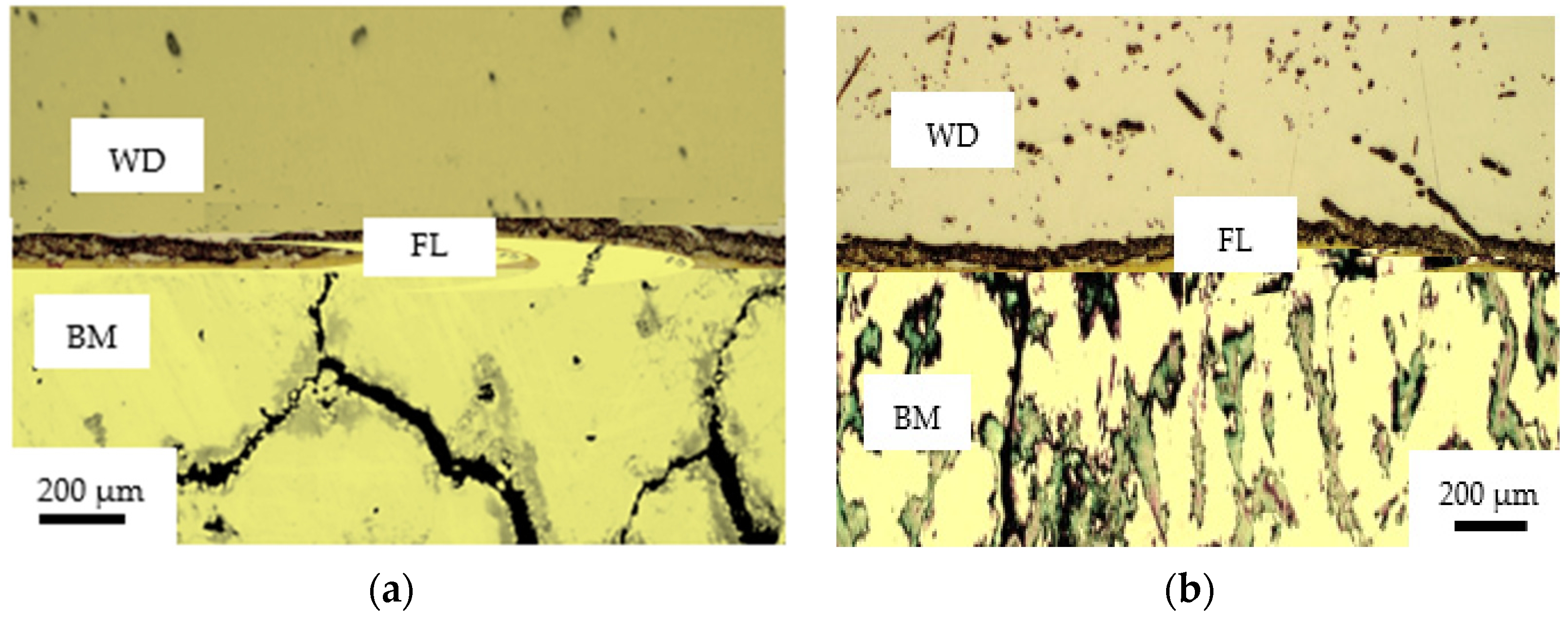
2.3.3. Analysis of the Metallographic Structure of the Transition Area between the Metal Deposited by Welding and the Base Material

In order to identify the homogeneity of the materials in the case of trimming die plated by hot and cold welding, an analysis of the metallographic structure in the transition area between the metal deposited by welding and the base material was performed. This analysis focused on identifying the metallographic structure of the base material, the material in the heat-affected zone (HAZ) and the diffusion zone, and the material deposited by welding. The research on establishing the homogeneity of the metallographic structure was performed using a scanning electron microscope FEI Inspect-F (SEM, Thermo Fisher, Tokyo, Japan), equipped with an energy dispersion spectroscopy detector (Thermo Fisher, Tokyo, Japan).

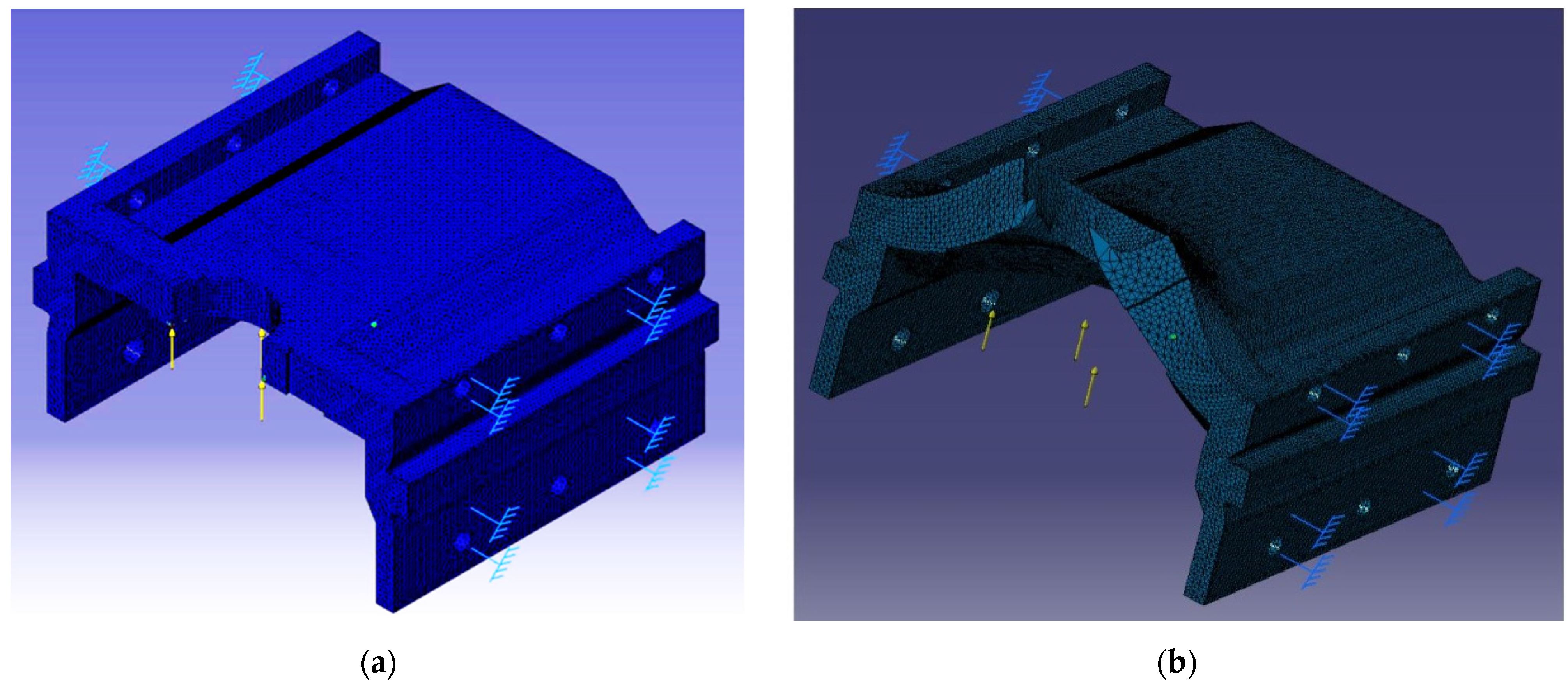
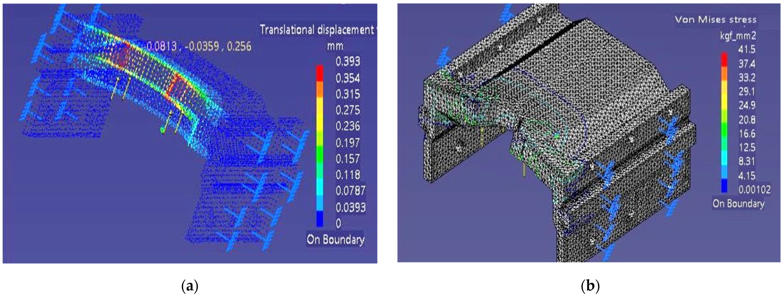
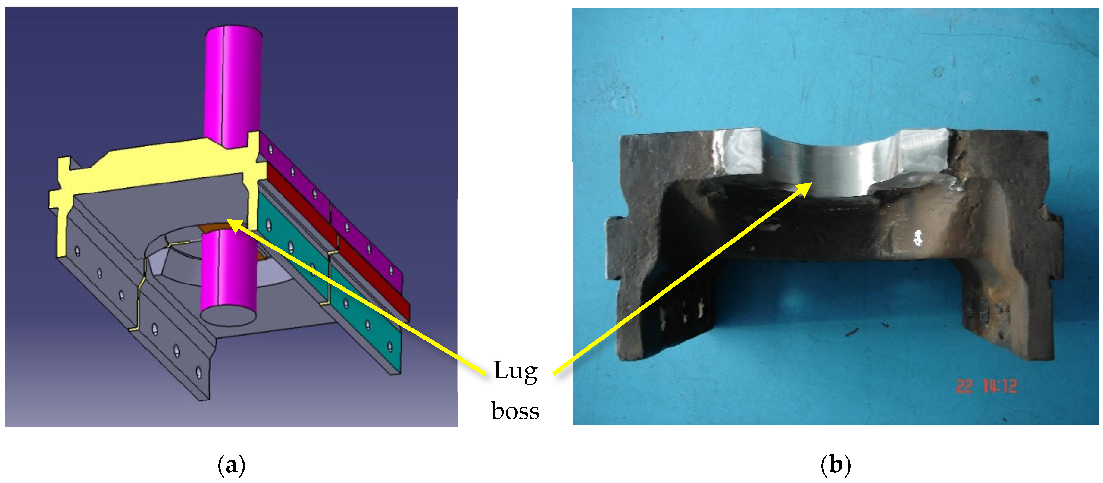
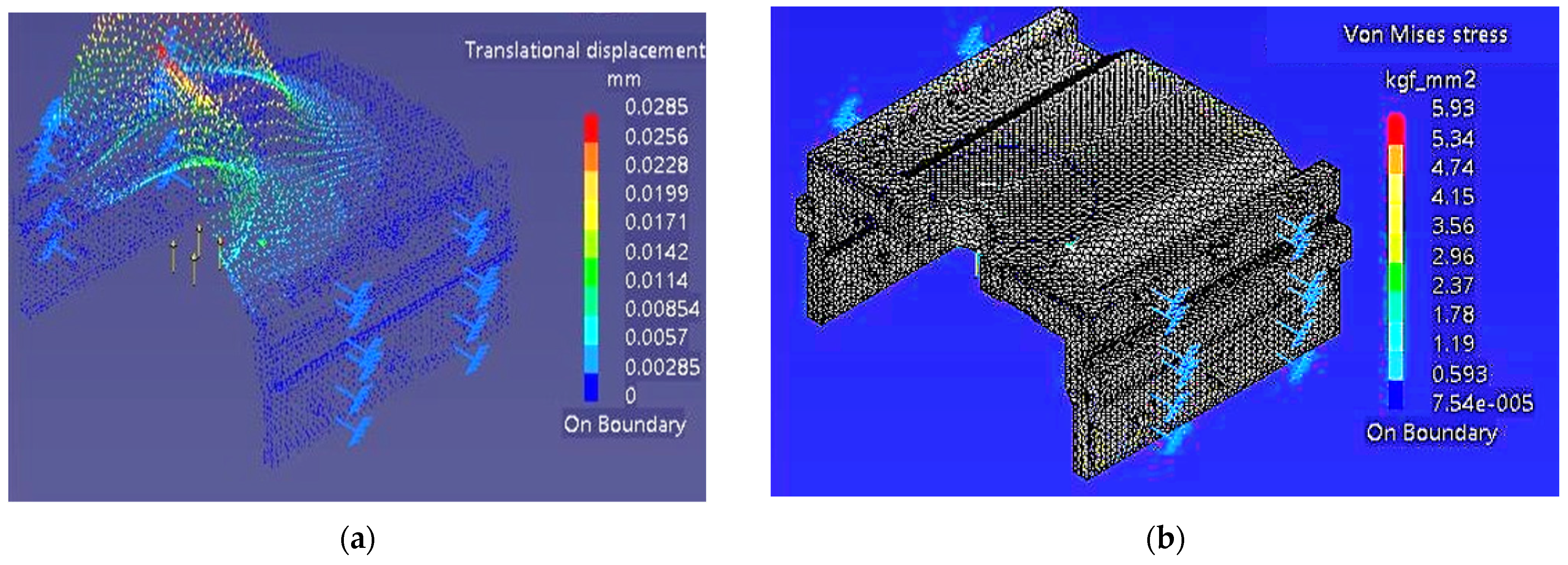
2.4. Redesigning the Trimming Die Geometry Using FEM

Because in many cases the redesign of the geometry of the trimming dies could be the technical solution to increase their durability, the next stage of research was aimed at designing an optimal geometry for the active part of the trimming dies. The finite element method (FEM) was used to redesign the shape of the trimming dies. The analyses performed were dynamic, explicit, and were performed using ANSYS (academic version: 18.0, ANSYS, Inc., Canonsburg, PA, USA). In this respect, a remodelling of the active part of the trimming dies was mainly considered in order to obtain an increase in their durability.

3. Results and Discussions

The experimental research activity and its practical application were possible due to a collaboration with the company ALRO Slatina, Romania. Thus, all the results obtained in the experimental research were closely related to the practical activity specific to the aluminum manufacturing industry.

3.1. Analysis of the Durability of Trimming Dies Made of Different Materials

After making the trimming dies, they were tested in the production process, and their wear was monitored. Thus, it was followed the way in which the process of cleaning the bars is carried out, and it was considered that the maximum allowed dimensional wear should not exceed a value of 0.5 mm. Thus, the wear was determined by measuring the diameter of the cleaned bars at intervals of 10 min. Regarding the durability of the trimming dies made of the five materials, it was assessed by the number of stress cycles until which the maximum allowable wear was obtained. The values obtained, for sustainability, following the experimental research carried out are presented in Table 5.
Following the research, it was found that the trimming dies made of K360 steel showed the highest durability. This confirms that a large amount of alloying elements, present in the chemical composition of this steel, but also a high hardness of 65 HRC, obtained after heat treatment hardening, are factors that can contribute to increasing the durability of trimming dies [20,21]. However, certain areas with cracks have been observed on the active surfaces of the trimming dies (Figure 5), which shows that this steel is very sensitive to mechanical shocks and is not very suitable to be used to make this type of trimming dies.
The lowest durability had it a trimming die made of K105 steel, and this can be explained by the fact that, in the case of this steel, the lowest hardness was obtained after the heat hardening treatment, 58 HRC, which has low mechanical properties, compared with other steels. Thus, it is confirmed that trimming die-type tools may have low durability if they are made of steels with low mechanical properties [22,23]. The very important thing is that no cracks were observed on the active surfaces of the trimming dies made of K105 steel, which demonstrates its high resistance to mechanical shocks. Although the material in the active surface of the trimming dies did not break, large deformations of the material in the active area appeared instead due to shear stresses, which manifested themselves in the form of material flows (Figure 6).
The results obtained in the stage of choosing a new optimal material for trimming dies, which would allow increasing their durability, were not in line with expectations, in the sense that the replacement of the steel commonly used to make trimming dies, X210Cr12, with K360 steel, a determined only an increase in the durability of the trimming die, with a reduced value of about 10%, although the costs of making the trimming die have increased three times. It should also be noted that the other steels used in making the trimming dies (K105; K107, K110; K460) caused only an insignificant change in the durability of the trimming dies, below 10%, in relation to the situation where, for the production of the trimming die, X210Cr12 steel would be used. In these circumstances, it can be concluded that the use of new materials is not an optimal technical solution, and in this regard, we have moved to the next stages of research that considered the application of a coating technology by welding the active surface of the trimming dies, respectively the optimization of the geometry of the active part of the trimming dies using the finite element method (FEM).

3.2. The Influence of Plating Technology Through Welding on the Durability of Trimming Dies

Given that the research was carried out in the sense of using a new material optimal for the realization of the trimming dies, both from a technical and economic point of view, the expected results were not obtained, in this stage, research carried out considered the application of technologies by plating through welding the active part of trimming dies. The purpose of these technologies was to increase the durability of the trimming dies in terms of low costs. In addition, given that K105 steel is cheaper and, in its case, the trimming dies did not show tendencies to crack, it was the basic material used to make the trimming dies at this stage of the research.
During the application of hot welding plating technology, a major inconvenience was the handling of the trimming die during the welding operation due to its large size and weight. The filler materials were used in accordance with the manufacturers’ recommendations, only in welding position A, i.e., the vertical one. The observance of this welding position was determined by the presence of the alloying elements that are found in the electrode coating. By observing the vertical welding position during welding, the conditions are met for the alloying elements to remain gravitationally at the base of the metal bath. If other welding positions had been used, the alloying of the two materials in the electrodes, respectively the trimming die, would not have been performed in the best conditions. Given the above, it was necessary that during the whole period of depositing the welding layers on the active surface of the trimming die to be plated, to be always positioned horizontally, a rather difficult thing due to the weight of the trimming die and the working temperature, 500 °C.
The cold welding plating technology of the active part of the trimming die was achieved by heating the material to a temperature in the range of 150–180 °C. This was determined taking into account the temperature at which the possible bonding between the base material of the trimming die (K105) and the filler material in the deposited intermediate layer is possible STARINOX 309L [24].
Given the fact that the temperature of the trimming die material had to be maintained in the range of 150–180 °C, during the entire period of deposition of the layers by welding, monitoring of the temperature of the part material was performed using an EC060 infrared thermography chamber. The images of the temperature distribution in the heated trimming die material are shown in Figure 7.
From the analysis of the temperature distribution in the material (Figure 7), it was found that the temperature value of approximately 180 °C was reached only in the active area of the trimming die where the welding beads were also deposited. In addition, the temperature values of the trimming die material in the other areas of the trimming die were maintained at much lower values in the range 130–140 °C.
The analysis of the two technological variants of plating by welding found that the technological variant of plating by cold welding has a great advantage, related to the fact that the trimming die material is heated to a lower temperature than in the case of hot plating, and, thus, no internal tensions appear in it. In addition, both energy consumption and the duration of the technological process were much shorter than in the case of hot plating. All these aspects have allowed the cold welding plating to be carried out in better technological conditions compared to the hot welding plating. From the point of view of the application of both hot and cold welding plating technology, the most difficult was to perform the plating of the trimming die made of K360 steel, and the easiest was in the case of the trimming die made of K105 steel. This can be explained by the difference in the chemical composition of the two steels, which causes changes in the technological property of weldability [25].
The two trimming dies were tested in production, finding that their durability increased compared to the situation when the trimming die was made only of K105 steel with a percentage of about 15% in the case of cold welding plating (N = 409,458) and with a percentage of approximately 19% in the case of hot welding plating (N = 426,002). In the case of hot welding plating, the durability of the trimming dies was higher compared to those plated by welding, but the difference in durability was insignificant.
Thus, research has shown that, from a technical and economic point of view, it is recommended that the trimming die be made of a cheaper material (K105), over which to be deposited, by welding, a layer of intermediate material with STARINOX 309L electrodes, previously covered by a layer of material using Tooltrode60 electrodes.
Following the analysis of the temperature distribution in the trimming die material, we also performed an analysis of the metallographic structure of the transition area between the metal deposited by welding and the base material (Figure 8). This analysis was necessary because different metallographic structures may occur in the case of the two types of plating through welding. Thus, in the case of cold welding plating of the trimming die, it was observed that an unfavorable metallographic structure appears, characterized by the appearance of cracks in the base material below the fusion line (Figure 8a). Under these conditions, the reduced durability of the trimming die, obtained by cold welding plating, can be explained.
In the case of hot-welded trimming die, at the interface between the welded metal (WD) and the base material (WB), it is delimited by a narrow area where the segregation of intermetallic compounds occurred (Figure 8b). The heat-affected zone (HAZ) is relatively narrow, about 600 µm, and no crack imperfections are present. In addition, in this case, a slight increase in the granulation in the base material was observed in the immediate vicinity of the fusion line (FL). These results confirm that hot welding plating for these types of alloy steels allows obtaining more homogeneous metallographic structures, with positive effects on the durability of the trimming die [26,27].

3.3. FEM Modeling of Trimming Die Geometry

Research conducted from the point of view of choosing an optimal material for the trimming die, but also from the point of view of welding plating technologies, has shown that there has been no considerable increase in the durability of these trimming dies. Thus, even if an optimal material has been established from which the trimming die can be made and optimal plating technology, the problem of growing in a higher percentage of the durability of these trimming dies remains to be solved. In this sense, in this stage of research, the aim was to optimize the geometry of the active part of the trimming dies by applying FEM. This decision was made because optimizing the geometry of the tools can be a technical solution to increase their durability [28,29]. Because the difference in durability obtained for trimming dies made of K105 and K360 steel is not large, but K360 steel is much more expensive, in this stage of research were analysed trimming dies made of K105 steel. In the first stage of modelling using FEM, the geometric shape and dimensions of the commonly used trimming dies were taken into account. Thus, the FEM analysis can provide information on the state of stresses and deformations that occur in the material of the trimming dies and that can significantly influence their durability. For the application of FEM, on each trimming die were arranged the loads, respectively the restrictions to which they are subjected (Figure 9), and by applying FEM were analysed the deformations and equivalent stresses that appear in the material of the trimming die (Figure 10).
Following the application of FEM for the commonly used trimming die (Figure 10a), it was observed that high values of deformations were obtained, of approximately 0.393 mm located mainly in the central area of the active part of the trimming die. In addition, the maximum values of the equivalent stresses (Figure 10b) were also obtained in the central area of the active part of the trimming die and had values of 41.5 kgf/mm2. This demonstrates that the central area of the active part of the trimming die is in high demand, which required a redesign of the trimming die geometry for this area. Thus, the active zone of the trimming die was redesigned in the sense that, on a sector of a circle with an angle of 60°, a lug boss with a thickness of 10 mm was provided (Figure 11). In these conditions, it was considered that the realization of this lug boss in the active area of the trimming die by 1/3 of the length can cause an increase in the durability of the trimming die by considerably reducing the state of stresses and deformations.
For the application of FEM, in the case of the modified geometric shape trimming die, the same loads and restrictions were kept as in the case of the old geometric shape trimming die. Following the application of FEM for the new trimming die, different values of deformations and equivalent stresses were obtained (Figure 12).
From the analysis of the values obtained for deformations (Figure 12a), it was observed that, in the case of the trimming die with the new geometric shape, they are approximately 13.8 times smaller than in the case of the trimming die with the old geometric shape. In addition, in the case of the trimming die with the modified geometric shape, it was observed that there is a reduction in the equivalent stresses (Figure 12b), about seven times compared to the equivalent stresses in the old trimming die. Substantially reducing the values of deformations and stresses in the trimming die material can lead to a high increase in its durability. Following this analysis, in the next stage of research was made the trimming die with the modified geometric shape (Figure 11). This change in the geometric shape of the trimming die led to a small increase in manufacturing costs by about 9%. Thus, a trimming die can be obtained that can be optimal in terms of durability without involving very high costs.
After making the trimming dies, they were tested in practice, and it was found that they performed very well in operation, having considerably higher durability compared to the trimming die made with the old geometry. Thus, following the experimental research, the average durability of the trimming die was established, made of K105 steel, of approximately N = 1,050,000 cycles, which demonstrates that the durability of the trimming die with the new construction form increases about three times compared to the trimming die with the old geometric shape. This demonstrates that the solution to increasing the durability of the trimming die is to adopt an optimal geometry of the active part at the expense of choosing an optimal material. It is also confirmed that in many cases, increasing the durability of a tool is possible by adopting an optimal geometry for the active part [30,31]. This demonstrates that the solution to increasing the durability of the trimming die is to adopt an optimal geometry of the active part at the expense of choosing an optimal material.

4. Conclusions

Increasing the durability of trimming dies used to clean anodes is a very important goal in order to reduce the costs involved in obtaining aluminum.
Many attempts have been made to choose an optimal material from which to make the trimming die. It turned out that the highest durability of the trimming dies was obtained for the situation in which they are made of K360 steel. However, the increase in the durability of the trimming die was not significant in the case of using K360 steel, but the costs of making the trimming die increased greatly. This has shown that the choice of an optimal material for the execution of the trimming die does not provide us with appropriate results.
As, research has shown that, from a technical and economic point of view, it is indicated that the trimming die must be made of a cheaper material (K105), over which to be deposited by welding a layer of intermediate material with STARINOX 309L electrodes on which it was deposited a layer of material using Tooltrode60 electrodes. In addition, the analysis of the metallographic structure of the transition area between the metal deposited by welding and the base material showed that hot welding plating allows obtaining a more homogeneous metallographic structure compared to cold welding plating.
Change in the trimming die geometry determined a reduction in deformations of about 13.8 times and of the equivalent stresses of about 7 times compared to those obtained in the case of the old trimming die. In addition, the durability of the trimming die with the new construction shape increases approximately three times compared to the trimming die with the old geometric shape. This demonstrates that the solution to increasing the durability of the trimming die is to adopt an optimal geometry of the active part at the expense of choosing an optimal material.
Future directions of research will focus on further optimizing the geometric shape of the active area of the trimming die and choosing the best material from which to make the trimming die in relation to it.

Author Contributions

Conceptualization, D.G., C.B., G.G. and D.D.; methodology, validation, C.M., M.D. and L.C.D.; formal analysis, S.-G.R., L.C.D., G.G. and D.G.; investigation, D.G., C.B. and G.G.; resources, D.G., C.B., G.G. and D.D.; data processing, D.G., C.B., G.G., C.M. and S.-G.R.; writing—original draft preparation, D.D. All authors have read and agreed to the published version of the manuscript.

Funding

This research received no external funding.

Conflicts of Interest

The authors declare no conflict of interest.

References

  1. Boqiang, L.; Lin, X. Energy conservation of electrolytic aluminium industry in China Renew. Sustain. Energy Rev. 2015, 43, 676–686. [Google Scholar]
  2. Yue, W.; Chen, X.; Gui, W.; Xie, Y.; Zhang, H. A knowledge reasoning fuzzy-Bayesian network for root cause analysis of abnormal aluminium electrolysis cell condition. Front. Chem. Sci. Eng. 2017, 11, 414–428. [Google Scholar] [CrossRef]
  3. Sysoev, I.A.; Ershov, V.A.; Kondrat’ev, V.V. Method of Controlling the Energy Balance of Electrolytic Cells for Aluminum Production. Metallurgist 2015, 59, 518–525. [Google Scholar] [CrossRef]
  4. Das, S.K.; Green, J.A.S. Aluminum industry and climate change—Assessment and responses. JOM 2010, 62, 27–31. [Google Scholar] [CrossRef]
  5. Goupil, G.; Bonnefont, G.; Idrissi, H.; Guay, D.; Roué, L. Consolidation of mechanically alloyed Cu–Ni–Fe material by spark plasma sintering and evaluation as inert anode for aluminum electrolysis. J. Alloy. Compd. 2013, 580, 256–261. [Google Scholar] [CrossRef]
  6. Helle, S.; Tresse, M.; Davis, B.; Guay, D.; Roué, L. Mechanically Alloyed Cu-Ni-Fe-O Based Materials as Oxygen-Evolving Anodes for Aluminium Electrolysis. J. Electrochem. Soc. 2012, 159, E62. [Google Scholar] [CrossRef]
  7. TUPY. Continuous Cast Iron Bars. 2018. Available online: http://www.tupy.com.br/ingles/produtos/perfisprocesso.php (accessed on 25 May 2021).
  8. Da Silva, R.B.; Lima, M.L.S.; Pereira, M.F.; Abrão, B.S.; da Silva, L.R.R.; Bianchi, E.C.; Machado, A.R. A surface and sub-surface quality evaluation of three cast iron grades after grinding under various cutting conditions. Int. J. Adv. Manuf. Technol. 2018, 99, 1839–1852. [Google Scholar] [CrossRef]
  9. Kumar, K.; Arun, K.; Sathishkumar, N.; Narayanan, M.P.; Raviraj, E. Experimental investigation on the machinability of nodular ductile iron with cubic boron nitride and tungsten carbide inserts. Mater. Today Proc. 2021, 39, 1386–1389. [Google Scholar] [CrossRef]
  10. Kumar, K.; Hariharan, P. Prediction and investigation of surface roughness while turning sg iron with cubic boron nitride (cbn) and tungsten carbide inserts. Trans. Can. Soc. Mech. Eng. 2017, 41, 129–141. [Google Scholar] [CrossRef]
  11. Nayyar, V.; Kamiński, J.; Kinnander, A.; Nyborg, L. An Experimental Investigation of Machinability of Graphitic Cast Iron Grades; Flake, Compacted and Spheroidal Graphite Iron in Continuous Machining Operations. Procedia CIRP 2012, 1, 488–493. [Google Scholar] [CrossRef]
  12. Fiorini, P.; Byrne, G. The influence of built-up layer formation on cutting performance of GG25 grey cast iron. CIRP Ann. 2016, 65, 93–96. [Google Scholar] [CrossRef] [Green Version]
  13. Kalyon, A.; Günay, M.; Özyürek, D. Application of grey relational analysis based on Taguchi method for optimizing machining parameters in hard turning of high chrome cast iron. Adv. Manuf. 2018, 6, 419–429. [Google Scholar] [CrossRef]
  14. Ravi, A.M.; Murigendrappa, S.M.; Mukunda, P.G. Machinability Investigations on High Chrome White Cast Iron Using Multi Coated Hard Carbide Tools. Trans. Indian Inst. Met. 2014, 67, 485–502. [Google Scholar] [CrossRef]
  15. Sahoo, A.K.; Sahoo, B. Performance studies of multilayer hard surface coating (TiN/TiCN/Al2O3/TiN) of indexeble carbide insert in hard machining: Part-II (RSM, grey relational and techno economical approach). Measurement 2013, 46, 2868–2884. [Google Scholar] [CrossRef]
  16. Tu, L.; Shi, W. Establish Using FEM Method of Constitutive Model for Chip Formation in the Cutting Process of Gray Cast Iron. Metals 2019, 10, 33. [Google Scholar] [CrossRef] [Green Version]
  17. Savkovic, B.; Kovac, P.; Dudic, B.; Gregus, M.; Rodic, D.; Strbac, B.; Ducic, N. Comparative Characteristics of Ductile Iron and Austempered Ductile Iron Modeled by Neural Network. Materials 2019, 12, 2864. [Google Scholar] [CrossRef] [PubMed] [Green Version]
  18. Li, H.; Li, T.; Gong, M.; Wang, Z.; Wang, G. Finite Element Analysis of Dynamic Recrystallization of Casting Slabs during Hot-Core Heavy Reduction Rolling Process. Metals 2020, 10, 181. [Google Scholar] [CrossRef] [Green Version]
  19. Haines-Gadd, M.; Chapman, J.; Lloyd, P.; Mason, J.; Aliakseyeu, D. Emotional Durability Design Nine—A Tool for Product Longevity. Sustainability 2018, 10, 1948. [Google Scholar] [CrossRef] [Green Version]
  20. Voestalpine Delstahl. Available online: https://www.bohler-edelstahl.com/en/products (accessed on 25 May 2021).
  21. Hawryluk, M.; Dobras, D.; Kaszuba, M.; Widomski, P.; Ziemba, J. Influence of the different variants of the surface treatment on the durability of forging dies made of Unimax steel. Int. J. Adv. Manuf. Technol. 2020, 107, 4725–4739. [Google Scholar] [CrossRef]
  22. Kaszuba, M. The application of a new, innovative, hybrid technology combining hardfacing and nitriding to increase the durability of forging tools. Arch. Civ. Mech. Eng. 2020, 20, 122. [Google Scholar] [CrossRef]
  23. Smirnov, A.E.; Plokhikh, A.I.; Ryzhova, M.Y.; Akinin, A.B.; Boev, S.V. Improving the Durability of Stamping Tools from Kh12MF Steel by Quenching in High-Pressure Nitrogen and Thermal Cycling. Met. Sci. Heat Treat. 2020, 62, 133–138. [Google Scholar] [CrossRef]
  24. Dhar, V.; Provino, A. Ferromagnetism in the orthorhombic PrPd and SmPd. J. Alloy. Compd. 2018, 762, 254–259. [Google Scholar] [CrossRef]
  25. Villalobos, J.C.; Del-Pozo, A.; Campillo, B.; Mayén, J.; Serna, S. Microalloyed Steels through History until 2018: Review of Chemical Composition, Processing and Hydrogen Service. Metals 2018, 8, 351. [Google Scholar] [CrossRef] [Green Version]
  26. Zorko, D.; Kulovec, S.; Duhovnik, J.; Tavčar, J. Durability and design parameters of a Steel/PEEK gear pair. Mech. Mach. Theory 2019, 140, 825–846. [Google Scholar] [CrossRef]
  27. Neamtu, G.V.; Mohora, C.; Anania, D.; Dobrotă, D. Research Regarding the Increase of Durability of Flexible Die Made from 50CrMo4 Used in the Typographic Industry. Metals 2021, 11, 996. [Google Scholar] [CrossRef]
  28. Dobrota, D. Optimizing the Shape of Welded Constructions Made through the Technique “Temper Bead Welding”. Metals 2020, 10, 1655. [Google Scholar] [CrossRef]
  29. Oliaei, S.N.B.; Karpat, Y.; Davim, J.P.; Perveen, A. Micro tool design and fabrication: A review. J. Manuf. Process. 2018, 36, 496–519. [Google Scholar] [CrossRef]
  30. Bobzin, K. High-performance coatings for cutting tools. CIRP J. Manuf. Sci. Technol. 2017, 18, 1–9. [Google Scholar] [CrossRef]
  31. Jiang, L.; Wang, D. Finite-element-analysis of the effect of different wiper tool edge geometries during the hard turning of AISI 4340 steel. Simul. Model. Pract. Theory 2019, 94, 250–263. [Google Scholar] [CrossRef]
Figure 1. Rod assembly—tetrapod: 1—aluminum bar; 2—bimetal plate; 3—rondon.
Metals 11 01157 g001
Figure 2. Anode assembly.
Metals 11 01157 g002
Figure 3. Presentation of the trimming dies used in the cleaning operation: (a)—cleaning trimming die—3D representation; (b)—image of the real trimming die used for cleaning.
Metals 11 01157 g003
Figure 4. Wear of the active parts of the half-trimming dies: (a)—accentuated wear, disposed approximately symmetrical on the entire length of the active part; (b)—accentuated asymmetrical wear.
Metals 11 01157 g004
Figure 5. The shape of the cracks that appear in the active area of the trimming dies made of the steel K360.
Metals 11 01157 g005
Figure 6. The shape of the material flows that appear in the active area of the trimming dies made of steel K105.
Metals 11 01157 g006
Figure 7. Distribution of temperatures when heating the trimming die. (a)—side view of the temperature distribution in the material in the active area of the trimming die, (b)—front view of the temperature distribution in the material from the active area of the trimming die, (c)—side view of the temperature distribution of the base material of the trimming die, (d)—front view of the temperatures distribution of the basic material of the trimming die.
Metals 11 01157 g007
Figure 8. The metallographic structure of the transition area between the metal deposited by welding and the base material: (a)—the metallographic structure in case of cold plating welding of the trimming die; (b)—metallographic structure in case of hot plating welding of the trimming die.
Metals 11 01157 g008
Figure 9. The loads and restrictions imposed on the trimming die for FEM modeling: (a)—undeformed trimming die; (b)—deformed trimming die.
Metals 11 01157 g009
Figure 10. Deformation values (a) and of the equivalent stresses (b).
Metals 11 01157 g010
Figure 11. Trimming die with the active part geometry modified: (a)—3D representation; (b)—the image of the real trimming die.
Metals 11 01157 g011
Figure 12. The deformation values (a) and equivalent stresses (b) for the trimming die with the modified active part geometry.
Metals 11 01157 g012
Table 1. The chemical composition of the steel used to make the trimming dies X210Cr12, %wt [20].
CCrMnSiNiPS
1.8110.20.20.50.030.035
Table 2. The physical properties of the steel used to make the trimming dies X210Cr12 [20].
Physical Properties20 °C200 °C400 °C
Density, Kg/dm37.707.657.60
Coefficient for thermal expansion (per °C from 0 °C)-11.0 × 10−610.8 × 10⁻⁶
Thermal conductivity (cal/cm·s °C)49 × 10−351.3 × 10−354.9 × 10⁻³
Specific heat0.110--
Modulus of elasticity, MPa194,000189,000173,000
Table 3. The chemical composition of the steels used to make the trimming dies, %wt [20].
MaterialCSiMnCrMoVWCo
K1051.600.350.3011.500.60.30.5-
K1072.10.250.411.5--0.7-
K1101.550.30.311.30.750.75--
K3601.250.90.358.752.71.18--
K4600.190.411.390.320.80.0312
Table 4. Mechanical properties of steels used in the execution of trimming dies [20].
MaterialYeld, Rp0,2, MPaImpact, KV/Ku JElongation, A, %Brinell Hardness, HBWModulus of Elasticity, GPa
K105≥497≥15112123894 (463 °C)
K107≥347≥22334242474 (571 °C)
K110≥212≥3213433967 (448 °C)
K360≥595≥1332213763 (423 °C)
K460≥731≥2241413755 (736 °C)
Table 5. Durability of trimming dies made of different materials.
MaterialNumber of Stress Cycles, N, Up to Which Maximum Allowable Wear Has Been Reached
K105357,458
K107369,573
K110376,231
K360384,598
K460373,435
Publisher’s Note: MDPI stays neutral with regard to jurisdictional claims in published maps and institutional affiliations.

