Abstract
The tensile creep behavior of Cr-Si alloys with Cr ≥ 91 at.% was investigated in air at 980 °C with a constant load of 50–100 MPa. Additionally, the influence of substitutional alloying additions of 2 at.% Ge and Mo, leading to ternary alloys was studied. The addition of Ge or Mo results in an improvement in creep strength, with the highest strength achieved with addition of Mo. For longer creep exposure times a strong effect is observed, because of severe nitrogen uptake from the air, depending on alloy composition. Based on the results a novel mechanism for the impact of chromium nitride formation on the creep behavior is proposed.
1. Introduction
New materials are required that can operate at higher temperatures to enable a further increase in efficiency of high temperature applications e.g., turbine engines. Refractory metals and refractory metal-based alloys offer the possibility for a further increase in working temperature due to their high melting points. Among the known refractory alloys, silicide systems such as Mo-Si-B, Nb-Nb5Si3 and Cr-Cr3Si offer promising properties [1,2,3]. The Cr-Si system offers the lowest density of about 6.5 g/cm3 [4], which is significantly lower than the 8–9 g/cm3 of commercially used superalloys. A reduction in weight in addition to higher operating temperatures would increase the efficiency of turbine engines. Like most pure metals, chromium shows low creep resistance at temperatures above 900 °C [5], however within the Cr-Cr3Si system the creep performance can be increased by precipitation strengthening [6]. The Cr-Si-(Ge/Mo) system studied in this work consists of Cr solid solution (Crss) with body-centered cubic structure and the cubic A15 phase with Cr3Si-stoichiometry.
A detailed description of the microstructure including precipitate formation during annealing at 1200 °C and hardness of such Crss-Cr3Si alloys with 2 at.% Ge, Pt, and Mo substitutions can be found elsewhere [7,8,9]. Mo is distributed evenly in both phases, while Ge segregates to the A15 phase. The precipitate phase volume fraction was found to be in the range of 24–31%. The hardness tests already proved the precipitation hardness effect and that the matrix and Cr3Si precipitates are semi-coherent embedded with improved coherency by Mo addition [7,9]. This also leads to a decreased microstructure coarsening during annealing [9]. Mo and especially Ge additions were also found to have positive effects on the oxidation resistance of the Cr-Si system that faces challenges such as volatilization of the otherwise protective chromium oxide above 1000 °C, or increased nitridation at temperatures above 900 °C in air [3,10,11]. Mo also leads to an improvement of the creep properties of Cr-silicide, as determined under compression [12,13,14]. Mo and Ge alloying affect Cr toughness beyond improving creep resistance [15,16], e.g., alloying pure Cr with 0.2 mol% Mo lowers the minimum creep rate [17] under pressure, which was also proven for Mo additions as solid solution strengthener in Cr(Ta)-Cr2Ta alloys [15,18,19]. Under tensile loads, on the other hand, very little creep data of strengthened Cr-alloys is available, especially in air. The few publications either focus on dispersion hardening by carbides, or on precipitation hardening by Laves -phases (Cr2X with X = Ta, Nb, Hf) [15,20,21,22,23].
The investigated alloys in this work are a binary alloy consisting of Cr and 9 at.% Si (Cr91Si9) and two ternary alloys consisting of 7 at.% Si and 2 at.% Ge or Mo, respectively (Cr91Si7Ge2 and Cr91Si7Mo2). For ternary alloying 2 at.% Si was replaced by the addition of 2 at.% Ge or Mo. The tensile creep properties of these Cr-rich Cr-Si-alloys were investigated at 980 °C in air.
2. Materials and Methods
All specimens were prepared in an arc-melting furnace (Edmund Bühler, Germany) on a water-cooled copper mold in an Ar atmosphere of 500 mbar. The raw materials were Cr (Cr > 99.95 wt.%, Plansee SE, Reutte, Austria), Si (Si > 99.999 wt.%, Alfa Aesar, Haverhill, MA, USA), Ge (Ge > 99.999 wt.%, haines & maassen Metallhandelsgesellschaft mBH, Bonn, Germany), and Mo (Mo > 99.95 wt.%, Alfa Aesar). Melting of zirconium prior to the melting process captured the residual oxygen in the chamber. To ensure homogeneity, specimens were remelted six times followed by an annealing heat treatment at 1200 °C for 100 h with subsequent furnace cooling. The annealing step was carried out in sealed quartz glass ampules under vacuum.
The tensile creep test setup used with constant load was previously described in [24,25] with a radiation furnace. The miniature creep specimens had a cross section of approximately 1.9 × 1.9 mm2, a gauge length of 8 mm, and an overall length of 25 mm (see [26]). The creep strain was measured optically using a video extensometer. The specimens were heated at a rate of 10 K/min to 980 °C in lab air. For temperature control, a thermocouple was placed close to the gauge length of the specimen. After reaching the test temperature, the weight was applied stepwise in low load increments. The loads for each sample were 50, 75 and 100 MPa.
The specimens were examined by SEM (1540 EsB Cross Beam, Zeiss, Oberkochen, Germany) equipped with energy dispersive X-ray spectroscopy (EDS) in order to evaluate the microstructure and the composition after heat treatment and after creep experiments. Composition was measured by area measurements of 100 µm2 in the center of the specimen after heat treatment.
3. Results and Discussion
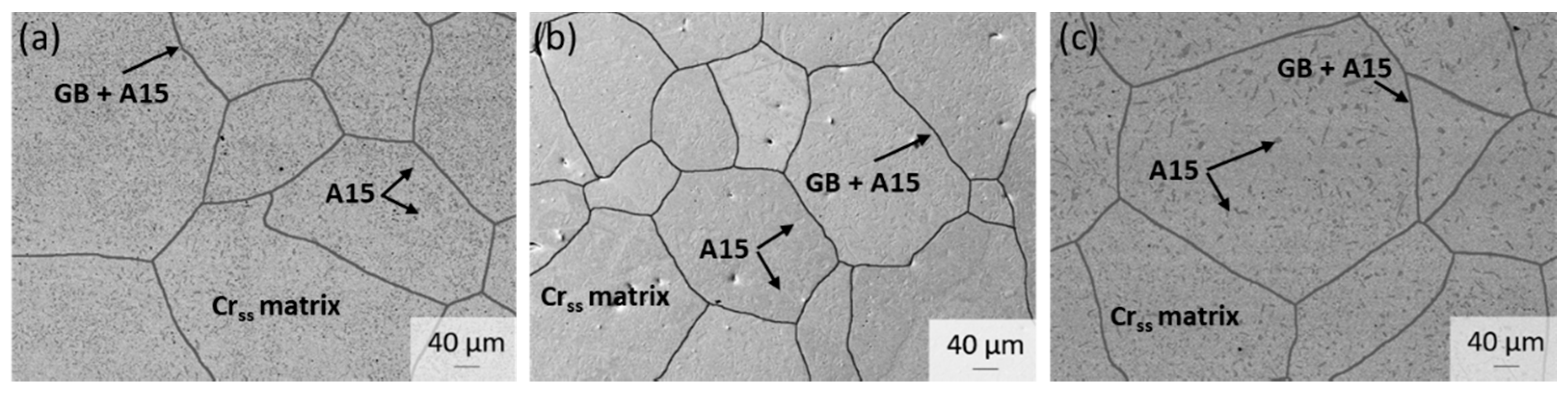
Figure 1 shows the microstructures of all investigated compositions after annealing for 100 h at 1200 °C. The microstructure consists of a Crss matrix with precipitates of an A15 Cr3Si intermetallic phase, which is in agreement with previous studies [7,8,9]. Since the specimens were not subjected to a solution heat treatment but only an annealing step, the microstructures of all alloys show coarser precipitates along the grain boundaries (GB) and finer precipitates inside the grains.

Figure 1.
Microstructures of (a) Cr91Si9, (b) Cr91Si7Ge2, and (c) Cr91Si7Mo2 alloy after annealing for 100 h at 1200 °C.
Table 1 lists the measured compositions of the tested alloys after heat treatment at 1200 °C for 100 h in vacuum. The actual Cr content differs slightly from the nominal composition due to Cr evaporation during melting.

Table 1.
Measured compositions of the tested binary and ternary alloys after melting and annealing at 1200 °C for 100 h.
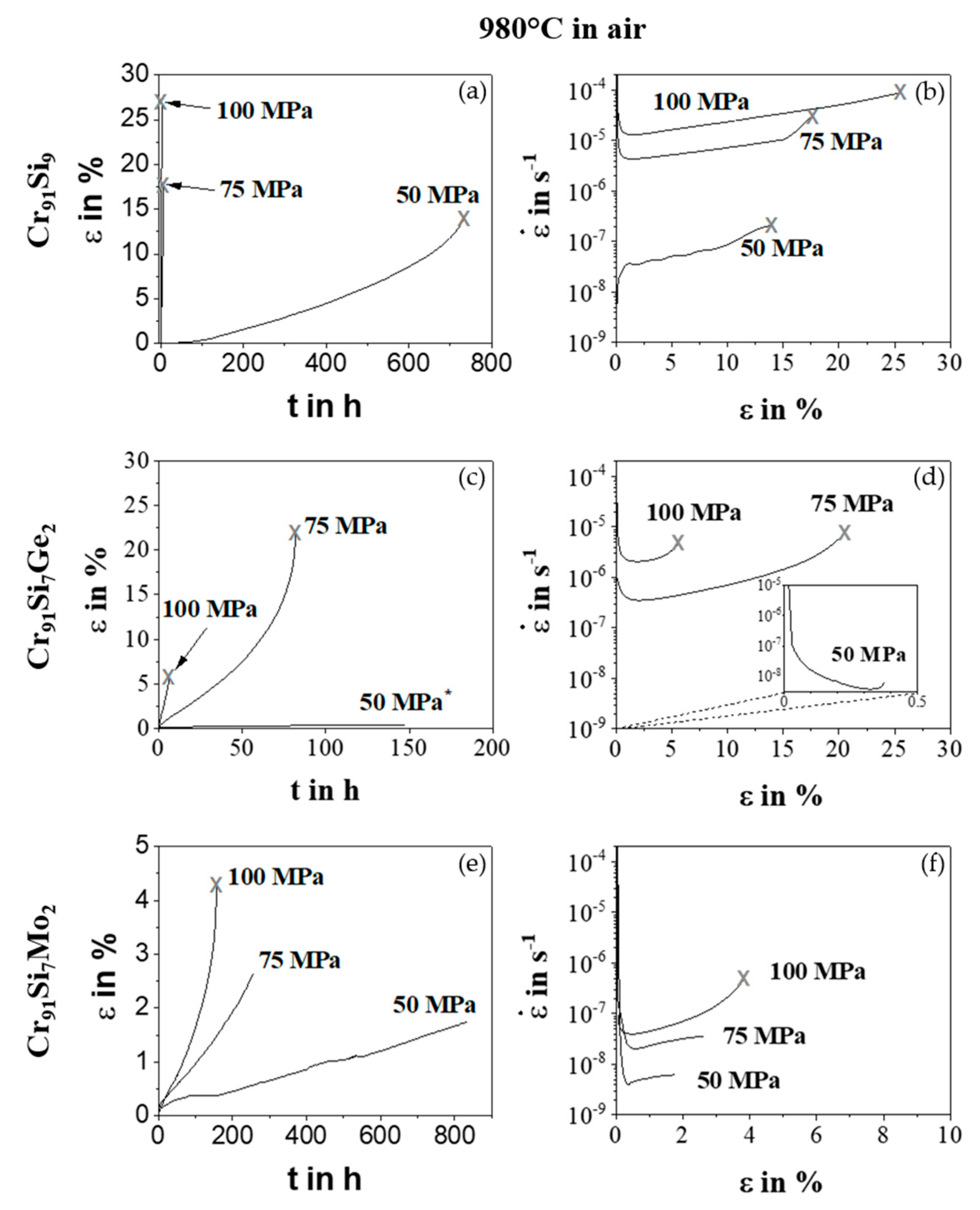
Figure 2 shows the obtained creep curve (strain ε vs. time t) and the plot of strain rate vs. strain ε for the alloys Cr91Si9, Cr91Si7Ge2, and Cr91Si7Mo2. After reaching a minimum creep rate and after several hundred hours, the Cr91Si7Ge2 with 100 MPa and Cr91Si7Mo2 with 75 MPa and 100 MPa experiments were interrupted. For a deeper understanding of the effect of a pretreatment on creep properties, the load of the 50 MPa sample of the alloy Cr91Si7Ge2 was increased to 65, 70, and finally 75 MPa after reaching the minimum creep rate. For this reason, the curve in Figure 2 ends after 150 h. Since all alloys show a plastic strain of 4% or higher, the ductile to brittle transition temperature (DBTT) was already exceeded. This is in agreement with the 0.2% proof stress results in compression tests of Aono et al. [27], where a decrease in 0.2% proof stress between 600–1200 °C of a Cr-Si alloy with 13 at.% Si is reported.
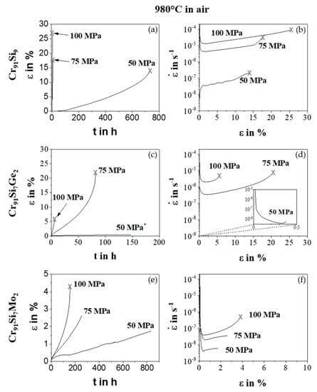
Figure 2.
Creep curves ε vs. t and vs. ε at 980 °C in air of the alloys Cr91Si9 (a,b), Cr91Si7Ge2 (c,d) and Cr91Si7Mo2 (e,f). Fractured samples are highlighted with an X at the end of the curve. In case there is no symbol, the test was aborted.
The samples of the binary Cr91Si9 alloy show an elongation between 15–25%. There is a large increase in time to failure between 50 MPa and 75 MPa or 100 MPa. The two higher load samples fail in less than 10 h, whereas the 50 MPa sample fractures after more than 700 h. In this case, the creep behavior resembles inverse primary creep behavior, which is typical for solid solution strengthened materials. This is a sign for an initial dislocation density, which is less than that, which is achieved during subsequent steady state creep with a constant dislocation density [28]. However, in this case it is assigned to nitridation, which also occurs stepwise and will be discussed in more detail in the following.
An improvement in creep strength is achieved by the substitution of 2 at.% Si by Ge (see Figure 2c,d as well as Figure 3). The samples still reach elongation in the range of up to 23% for loads ≥ 75MPa and additionally show a decrease in creep rate by one order of magnitude. The improved creep performance is attributed to a decrease in primary A15 precipitate formation at the grain boundaries [7].
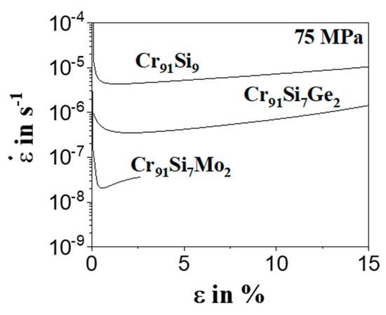
Figure 3.
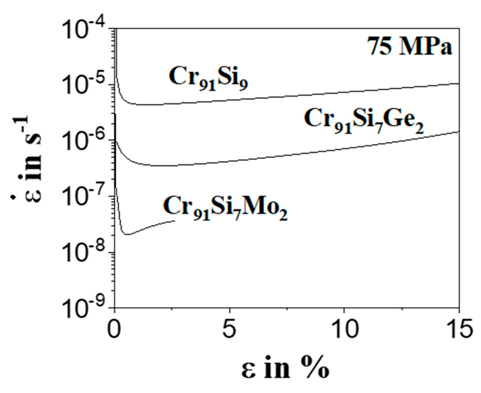
Strain rate vs. strain curve for the three alloys with a load of 75 MPa.
The substitution of 2 at.% Si with Mo leads to a further increase in creep strength (see Figure 2e,f). The samples reach a strain of up to 4%, which is somewhat lower than the binary alloy and the ternary alloy with Ge. Cr91Si7Mo2 with around 24% shows the lowest A15-phase fraction after annealing at 1200 °C for 100 h in comparison to the binary Cr91Si9 (~31%) and ternary Cr91Si7Ge2 (~29%) alloy [7]. Hence, the increase in volume fraction seems to play a significant role in the decrease of strain rates of the other alloys. In addition, alloying with Mo increases the materials grains (compare Figure 1). In comparison to the other two alloys, the formation of A15 precipitates at the grain boundaries was highly reduced by Mo alloying [7]. Even though Mo also leads to an increase in lattice parameters in Crss and the A15 phase and to an increased hardness in Crss [7], the change in creep properties is also attributed to grain boundary effects. This is in agreement with the investigations of the microstructures after creep experiments. All fractured samples of the tested alloys show an intergranular fracture. This finding is comparable to observations by Wilms et al. [15] on tensile creep specimens of Cr-based alloys (Cr > 90 wt.%).
Figure 3 shows the strain rate vs. strain curve of the 75 MPa samples. It shows even clearer the improvement in creep strength by adding Ge and Mo. The duration of the experiments is an additional factor that influences the creep properties of the Mo containing alloy and the Cr91Si9 and Cr91Si7Ge2 alloys tested at 75 MPa and 100 MPa. For a deeper investigation, additional experiments were carried out with the ternary Cr-Si-Ge alloy.
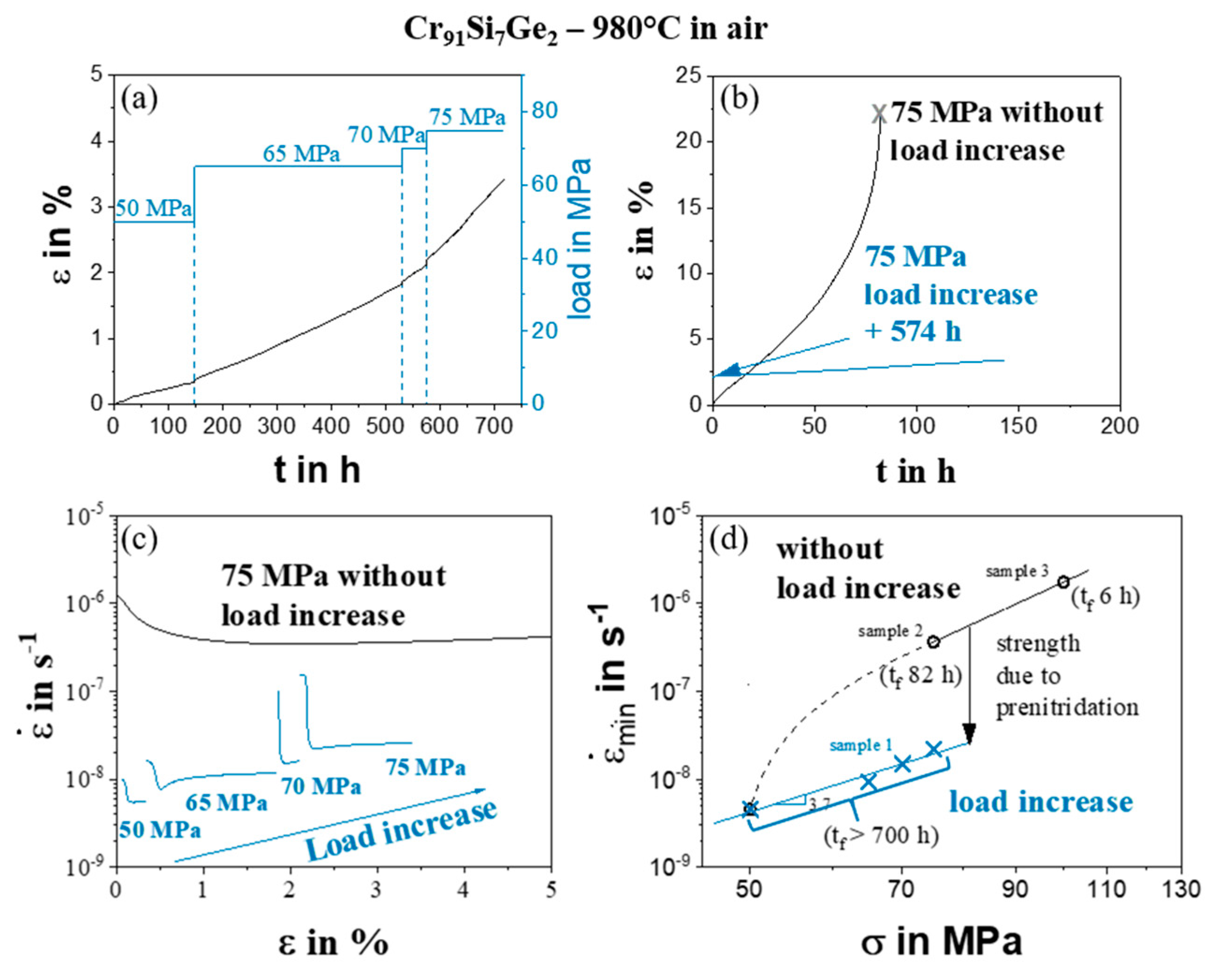
Figure 4 shows the influence of prolonged exposure in air on the creep properties of the Cr91Si7Ge2 alloy. A load increase from 50 to 65, to 70 and finally to 75 MPa was carried out. After reaching the minimum creep rate, the load is increased (see creep curve in Figure 4a). In Figure 4b the difference in strain over time of a pretested sample (574 h at 980 °C in air and 2% initial strain) and the original 75 MPa sample is plotted. Whereas the original sample reached more than 20% strain, the pretested sample achieves only 1% additional strain. Figure 4c shows this behavior even clearer.
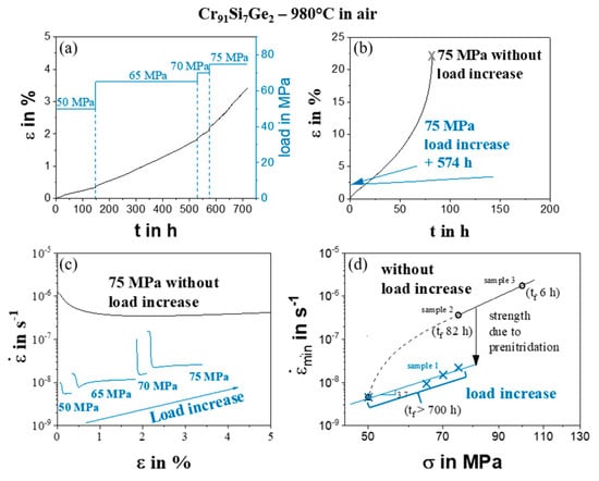
Figure 4.
Load increase of alloy Cr91Si7Ge2 at 980 °C in air. (a) Creep curve with increasing load from 50 to 75 MPa. (b) Comparison of 75 MPa strain curves (c) Comparison of strain rate vs. strain and (d) Norton-plot with minimum creep rate min versus stress of specimen with (blue—sample shown in Figure 4a) and without (black) prior load increase and time to failure (tf) in brackets. Sample 1, 2 and 3 refer to the samples shown in Figure 2c measured with constant loads of 50–75 MPa, 75 MPa and 100 MPa.
Figure 4d illustrates this behavior in the Norton-plot. The creep rate is reduced by approximately one order of magnitude due to the time-dependent mechanisms (e.g., increase in A15 volume fraction, dislocation density, internal oxidation and nitridation) affecting the creep behavior.
In the first place, the effect of temperature on the microstructure and precipitate formation is taken into account. As already described in [8] the solubility of alloying elements such as Si, Mo, and Ge decreases with decreasing annealing temperature. However, the effect is expected to be negligible for the observed significant changes in creep properties due to the following reasons: (i) For the Cr91Si7Ge2 composition the concentration of Si and Ge in Crss decreases by only 0.4 at.% in the temperature range between 1350 °C and 1050 °C and therefore it is expected that it is also comparable in the temperature range between 1200 °C (annealing) and 980 °C (creep tests) [8]. (ii) Annealing was found to predominantly increase the formation of small A15 precipitates inside Crss grains [7,8,9] rather than on the grain boundaries.
Impurities, such as oxygen and nitrogen, play an important role in the room-temperature (RT) ductility and embrittlement of pure Cr, but they also play a role at high temperatures [10,20,29]. At high temperatures, not only impurities but also oxygen and nitrogen affect the properties through internal oxidation and nitridation.
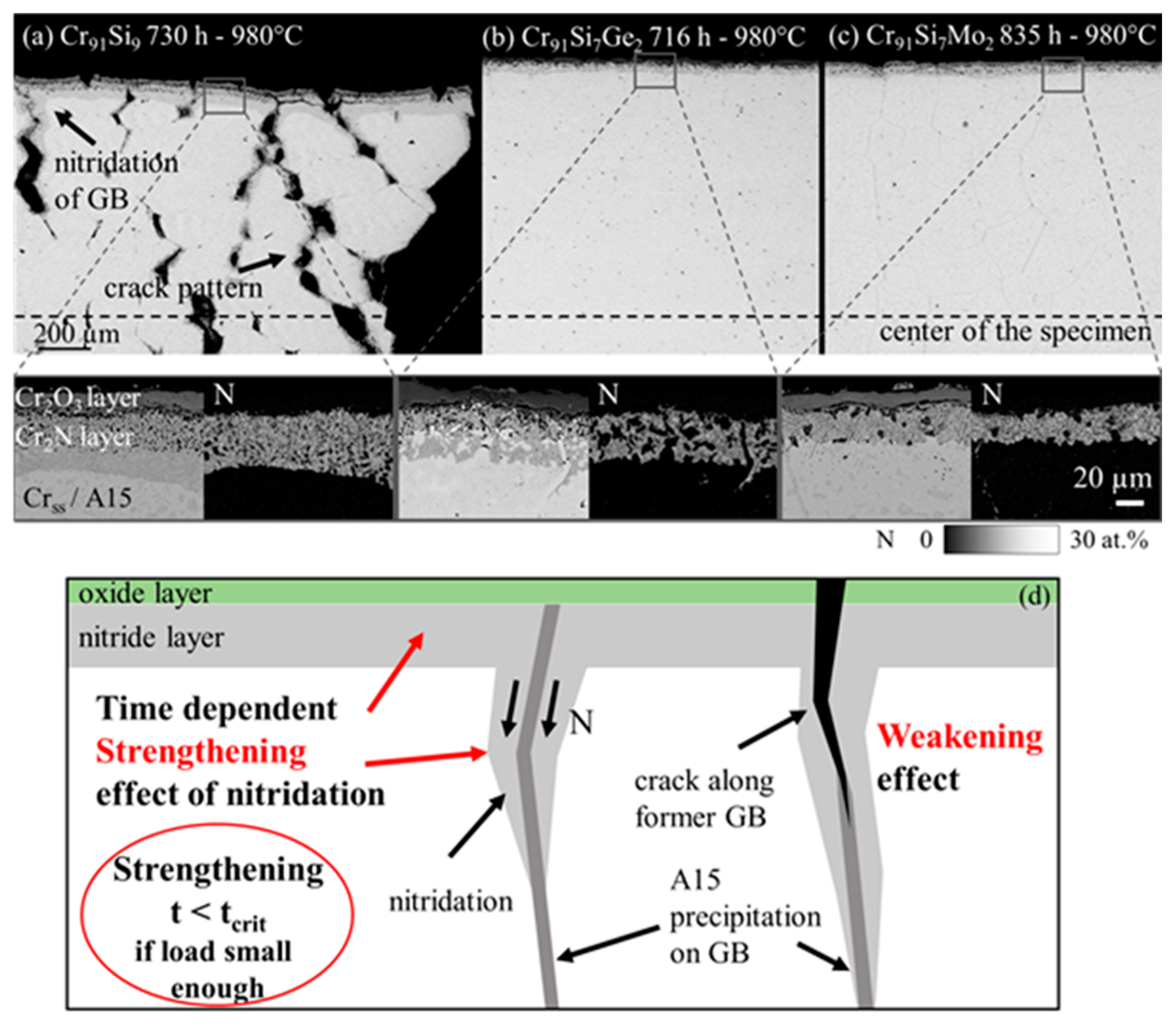
Figure 5a–c shows the back-scattered-electron (BSE) images of cross-sections as well as enlarged sections of the specimen’s surface with corresponding nitrogen element distribution maps of all compositions tested at 50 MPa.
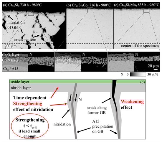
Figure 5.
BSE-images of the cross sections of all alloys tested at 50 MPa with details of the formed surface layer and corresponding N element distribution maps. (a) Cr91Si9, (b) Cr91Si7Ge2 and (c) Cr91Si7Mo2. (d) Schematic drawing of nitridation of the specimen surface, along grain boundaries (GB) and crack edges that can be beneficial due to a volume increase. At higher loads, embrittlement by nitridation results in much lower strain to failure.
Consistent with previous investigations [30], an oxide scale (Cr2O3) with a nitride layer (Cr2N) underneath forms during exposure in air. While Cr2N was only present in the surface layer of the ternary alloys, the binary alloy shows nitridation in the center of the specimens (see Figure 5a). Additionally, a crack pattern forms across the complete gauge length (compare Figure 5a), which becomes denser towards the fracture surface. The mechanism of nitridation of Cr and its alloys is explained in more detail elsewhere [31,32], however, recently it was stated and proven that a continuous Cr2O3 scale is intrinsically protective. Nitrogen and oxygen usually pass the Cr2O3 scale by a stepwise scale cracking and microcrack formation mechanism. Oxygen is consumed by scale healing while nitrogen diffuses into the interior of the sample, even in the mm range [9,19]. Especially for the rather long-run 50 MPa sample, the stepwise change in the creep behavior directly reflects this nitridation. At the higher stresses this nitridation steps are less obvious. In addition, the samples with Mo and Ge show much less nitridation, as these elements successfully lower the nitridation, either by stabilizing the nitridation resistant A15 Phase (Ge effect) or by increasing the nitridation resistance of the Crss (Mo effect) (compare Figure 4a–c) [30].
The 75 MPa and 100 MPa samples of Cr91Si9 and Cr91Si7Ge2 and the 100 MPa sample of Cr91Si7Mo2 show a high strain to failure. However, intergranular fracture occurs after a relatively short time and the specimens show cracks with nitrided edges over the entire cross section. The loads of 75 to 100 MPa lead to the formation of cracks, which grow quickly until failure. Alloying with Mo increases the creep strength and thereby the exposure time of the specimen at high temperatures. For longer testing times, a critical time of exposure can be observed, which also depends on the potential of the different formed scales to suppress nitridation and oxidation. Obviously, nitridation strongly influences the creep properties in air. If a sample is pretested, such as by the load increase shown in Figure 4, the formation of oxide and especially nitride increases.
Figure 5d shows a schematic drawing of the strengthening effect of nitrogen. The nitrogen effect is time and load dependent. Although the transformation of Cr metal into a Cr2N ceramic is usually causing embrittlement [3], if it occurs locally, it is also accompanied with a volume increase and thus can induce compression stresses, or even healing of crack tips. Eventually the nitride itself can be the origin of cracking and reduces the strain to failure as demonstrated for the pre-tested sample when 75 MPa load was applied. Thus, nitridation is only beneficial for slow deformation and slow crack propagation. It was also observed under isothermal oxidation [9] that nitridation proceeds into the substrate even without load along the grain boundaries, especially for binary Cr-Si alloys. For shorter times of exposure, no influence of nitridation on deformation is apparent and therefore the minimal creep rates are a good measure to reflect the impact of the alloying elements only.
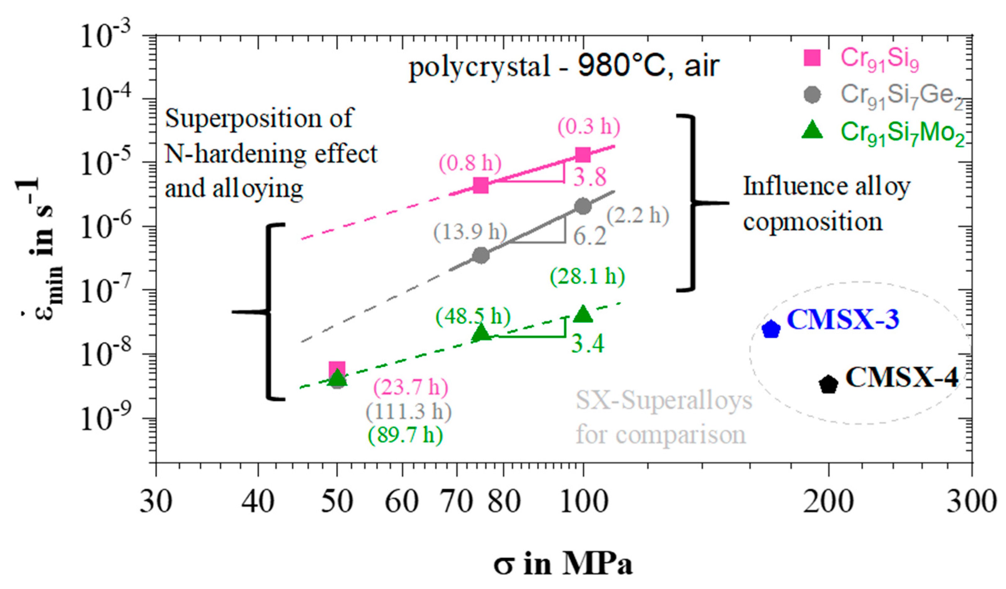
Figure 6 shows the Norton-plot of all alloys in comparison to two commercially available single crystal superalloys CMSX-3 and -4. The creep strength of the binary Cr91Si9 can be improved by up to one order of magnitude by the substitution of 2 at.% Si by Ge and two orders of magnitude by replacing 2 at.% Si by Mo. Again, this can be related to the amount of A15 precipitates located at grain boundaries which decreases from an area fraction of 7% for Cr91Si9 to around 0.2% for Cr91Si7Ge2 and 0% for Cr91Si7Mo2 [7]. It is interesting to note that the Norton exponent is higher for the alloy with germanium
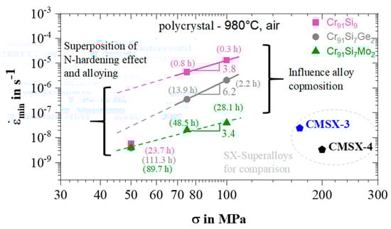
Figure 6.
Norton-plot of the tested polycrystalline alloys in comparison with the single crystalline Ni base superalloys CMSX-3 and CMSX-4 [33]. Values in brackets represent the time to reach minimum creep rate (tmin creep). It should be noted that comparison is made between polycrystalline materials of this study and single crystalline Ni-base superalloys.
In case of longer times, the situation becomes more complex, when the nitrogen uptake of the material and further strengthening as well as local weakening occurs. This needs further investigations. Little is known about these effects so far, but a similar study of an increase in creep strength was reported by Wilms et al. [20] for Cr-Ta alloys with small alloying additions of Si, Ti, and B. Compared to experiments carried out in argon atmosphere, samples tested in air show a decrease in creep rate and strain to failure similar to the Cr91Si7Ge2 sample tested in this work.
4. Conclusions
All of the studied Cr-base alloys show promising tensile creep properties at 980 °C in air and stresses between 50–100 MPa with strain to failure of 5–28%, as shown in Figure 2. Alloying additions of Ge and Mo lead to improved creep strength. All fractured samples exhibited intergranular fracture behavior. Precipitates of A15 phase weaken the grain boundaries and therefore grain boundary precipitation should be avoided by an appropriate solution heat treatment. A time and load dependent nitrogen effect is observed. After longer exposures in air at high temperatures and lower loads (50 MPa), internal nitridation is observed to influence the creep strength of these alloys. In this regime compression stresses are induced along grain boundaries or at crack tips of internal cleavage by the transformation into Cr2N. On the other hand, the time to failure is strongly reduced at higher loads due to embrittlement.
Author Contributions
Conceptualization and methodology, U.G. and M.C.G.; validation, A.S.U.; formal analysis, P.P.; investigation, P.P.; writing—original draft preparation, P.P.; writing—review and editing, All; supervision, project administration, funding acquisition, U.G. and M.C.G. All authors have read and agreed to the published version of the manuscript.
Funding
This work was supported by the German Research Foundation (DFG) [grant numbers GL 181/45 and GA 1074/2].
Institutional Review Board Statement
Not applicable.
Informed Consent Statement
Not applicable.
Data Availability Statement
Data reported results can be made available upon request.
Conflicts of Interest
The authors declare no conflict of interest.
References
- Perepezko, J.H. The Hotter the Engine, the Better. Science 2009, 326, 1068–1069. [Google Scholar] [CrossRef]
- Bewlay, B.P.; Jackson, M.R.; Subramanian, P.R.; Zhao, J.-C. A review of very-high-temperature Nb-silicide-based composites. Metall. Mater. Trans. A 2003, 34, 2043–2052. [Google Scholar] [CrossRef]
- Dorcheh, A.S.; Galetz, M.C. Challenges in Developing Oxidation-Resistant Chromium-Based Alloys for Applications Above 900 °C. J. Oper. Manag. 2016, 68, 2793–2802. [Google Scholar] [CrossRef]
- Fleischer, R.L.; Zabala, R.J. Mechanical properties of high-temperature titanium intermetallic compounds. Metall. Trans. A 1990, 21, 1951–1957. [Google Scholar] [CrossRef]
- Landau, C.S.; Greenaway, H.T.; Edwards, A.R. Some Properties of Chromium and Chromium-Tungsten Alloys. 1. Compression Creep Tests. J. Inst. Met. 1960, 89, 97–101. [Google Scholar]
- Shah, D.M.; Anton, D.L. Evaluation of refractory intermetallics with A15 structure for high temperature structural applications. Mater. Sci. Eng. A 1992, 153, 402–409. [Google Scholar] [CrossRef]
- Ulrich, A.S.; Pfizenmaier, P.; Soleimani, A.; Glatzel, U.; Galetz, M.C. Strengthened Cr-Si-base alloys for high temperature applications. Int. J. Refract. Met. Hard Mater. 2018, 76, 72–81. [Google Scholar] [CrossRef]
- Pfizenmaier, P.; Ulrich, A.S.; Galetz, M.C.; Glatzel, U. Determination of heat treatment parameters by experiments and CALPHAD for precipitate hardening of Cr-Alloys with Si, Ge and Mo. Intermetallics 2020, 116, 106636. [Google Scholar] [CrossRef]
- Ulrich, A.S. Entwicklung von Ausscheidungshärtbaren Cr-Si-Basis-Legierungen für Hochtemperaturanwendungen: Mikrostruktur und Oxidation; Shaker Verlag: Herzogenrath, Germany, 2020. [Google Scholar]
- Gu, Y.F.; Harada, H.; Ro, Y. Chromium and chromium-based alloys: Problems and possibilities for high-temperature service. J. Oper. Manag. 2004, 56, 28–33. [Google Scholar] [CrossRef]
- Smith, W.H.; Seybolt, A.U. Ductile Chromium. J. Electrochem. Soc. 1956, 103(6), 347. [Google Scholar] [CrossRef]
- Raj, S.V.; Whittenberger, J.D.; Zeumer, B.; Sauthoff, G. Elevated temperature deformation of Cr3Si alloyed with Mo. Intermetallics 1999, 7, 743–755. [Google Scholar] [CrossRef]
- Raj, S.V. An evaluation of the properties of Cr3Si alloyed with Mo. Mater. Sci. Eng. A 1995, 201, 229–241. [Google Scholar] [CrossRef]
- Raj, S.V. A preliminary assessment of the properties of a chromium silicide alloy for aerospace applications. Mater. Sci. Eng. A 1995, 192, 583–589. [Google Scholar] [CrossRef]
- Wilms, G.R.; Rea, T.W. The tensile creep properties of some extruded chromium alloys. J. Less Common Met. 1964, 6, 184–200. [Google Scholar] [CrossRef]
- Cruse, T.A.; Newkirk, J.W. Evaluation of methods to produce tough Cr3Si based composites. Mater. Sci. Eng. A 1997, 239, 410–418. [Google Scholar] [CrossRef]
- Matsumoto, Y.; Fukumori, J.; Morinaga, M.; Furui, M.; Nambu, T.; Sakaki, T. Alloying effect of 3D transition elements on the ductility of chromium. Scr. Mater. 1996, 34, 1685–1689. [Google Scholar] [CrossRef]
- Brady, M.P.; Zhu, J.H.; Liu, C.T.; Tortorelli, P.F.; Walker, L.R.; McKamey, C.G.; Wright, J.L.; Carmichael, C.A.; Larson, D.J.; Miller, M.K.; et al. Intermetallic reinforced Cr alloys for high-temperature use. Mater. High Temp. 1999, 16, 189–193. [Google Scholar] [CrossRef]
- Carlson, O.N.; Sherwood, L.L.; Schmidt, F.A. The effect of low percentage alloying additions on the ductility of iodide chromium. J. Less Common Met. 1964, 6, 439–450. [Google Scholar] [CrossRef]
- Wilms, G.R.; Ryan, N.E. Influence of atmospheric nitrogen on the creep properties of chromium-tantalum alloys. J. Less Common Met. 1967, 12, 11–18. [Google Scholar] [CrossRef]
- Pugh, J.W. The Tensile and Stress-Rupture Properties of Chromium. Trans. Am. Soc. Met. 1958, 50, 1072–1080. [Google Scholar]
- Stephens, J.R.; Klopp, W.D. High-temperature creep of polycrystalline chromium. J. Less Common Met. 1972, 27, 87–94. [Google Scholar] [CrossRef] [Green Version]
- Ryan. The formation, stability and influence of carbide dispersions in chromium. J. Less Common Met. 1966, 11, 221–248. [Google Scholar] [CrossRef]
- Völkl, R.; Fischer, B. Mechanical testing of ultra-high temperature alloys. Exp. Mech. 2004, 44, 121–127. [Google Scholar] [CrossRef]
- Völkl, R.; Fischer, B.; Beschliesser, M.; Glatzel, U. Evaluating strength at ultra-high temperatures-Methods and results. Mater. Sci. Eng. A 2008, 483, 587–589. [Google Scholar] [CrossRef]
- Mora-García, A.G.; Mosbacher, M.; Hastreiter, J.; Völkl, R.; Glatzel, U.; Muñoz-Saldaña, J. Creep behavior of polycrystalline and single crystal Ni-based superalloys coated with Ta-containing NiCoCrAlY by high-velocity oxy-fuel spraying. Scr. Mater. 2020, 178, 522–526. [Google Scholar] [CrossRef]
- Aono, Y.; Omori, T.; Kainuma, R. Microstructure and high-temperature strength in Cr–Si binary alloys. Intermetallics 2019, 112, 106526. [Google Scholar] [CrossRef]
- Burton, B. Inverse primary creep. Philos. Mag. A 1983, 48, 299–310. [Google Scholar] [CrossRef]
- Wilms, G.R. Environmental effects on the tensile creep properties of chromium alloys. J. Less Common Met. 1968, 14, 373–377. [Google Scholar] [CrossRef]
- Ulrich, A.S.; Pfizenmaier, P.; Solimani, A.; Glatzel, U.; Galetz, M.C. Improving the oxidation resistance of Cr-Si-based alloys by ternary alloying. Corros. Sci. 2020, 165, 108376. [Google Scholar] [CrossRef]
- Solimani, A.; Schütze, M.; Stark, A.; Galetz, M.C. Nitrogen transport through thermally grown chromia scales. Corros. Sci. 2018, 145, 180–190. [Google Scholar] [CrossRef]
- Ulrich, A.S.; Glatzel, U.; Galetz, M.C. Discontinuities in Oxidation Kinetics: A New Model and its Application to Cr–Si-Base Alloys. Oxid. Met. 2021, 95, 445–465. [Google Scholar] [CrossRef]
- Fleischmann, E.; Konrad, C.; Preußner, J.; Völkl, R.; Affeldt, E.; Glatzel, U. Influence of Solid Solution Hardening on Creep Properties of Single-Crystal Nickel-Based Superalloys. Metall. Mater. Trans. A Phys. Metall. Mater. Sci. 2015, 46, 1125–1130. [Google Scholar] [CrossRef]
Publisher’s Note: MDPI stays neutral with regard to jurisdictional claims in published maps and institutional affiliations. |
© 2021 by the authors. Licensee MDPI, Basel, Switzerland. This article is an open access article distributed under the terms and conditions of the Creative Commons Attribution (CC BY) license (https://creativecommons.org/licenses/by/4.0/).