Article

MWCNT-Reinforced AA7075 Composites: Effect of Reinforcement Percentage on Mechanical Properties

1
CINTECX, Universidade de Vigo, Encomat, 36310 Vigo, Spain
2
AIMEN Centro Tecnológico, 36410 O Porriño, Spain
*
Author to whom correspondence should be addressed.
Metals 2021, 11(6), 969; https://doi.org/10.3390/met11060969
Submission received: 17 May 2021 / Revised: 9 June 2021 / Accepted: 11 June 2021 / Published: 17 June 2021
(This article belongs to the Section Powder Metallurgy)

Abstract

:
Metal–matrix composites (MMC) of aluminium alloy 7075 (AA7075) containing 1 wt.% and 0.5 wt.% multiwall carbon nanotubes (MWCNTs) were developed by powder metallurgy, using a high energy ball milling (HEBM) process for dispersion of the MWCNTs. The powder of the AA7075-MWCNT obtained was characterized by X-ray diffraction (XRD) and scanning electron microscopy (SEM). The microstructural changes produced during the milling process, such as the modification of the crystallite size, as well as the micro-deformation of the matrix crystal lattice, were determined using the Scherrer formula. After consolidation into a strip shape using the hot powder extrusion (HPE) process at 500 °C, no porosity was detected and a fine homogeneous dispersion of the reinforcement into the matrix was obtained. After performing a 0.2 HV test and tensile tests in the extruded profiles of both composites, a better combination of properties was found in samples of AA7075-0.5 wt.% MWCNT, with the increase in measured ductility being especially remarkable.

1. Introduction

The intrinsic properties of carbon nanotubes (CNTs), such as extremely high Young’s modulus (1 TPa), very high strain to failure (100 GPa) [1] and electrical and thermal conductivities combined with their high aspect ratio, make them the most effective reinforcements to produce composite materials with. They have been successfully applied to the fabrication of high performance polymer–matrix composites [2,3,4], achieving significant improvements in their mechanical properties. However, the CNT’s potential use in metal–matrix composites has been limited due to the poor dispersion of its reinforcements, leading to poor mechanical properties.
The high tendency of CNTs to form clusters, their poor wettability of graphite by molten metal and the possible reaction between the matrix and the nanotubes at the interface [5,6] are especially challenging in the case of aluminium–matrix composites. Therefore, research is moving to solid phase processes, developing different routes to obtain the necessary uniform dispersion of the CNTs in aluminium to achieve effective load transfer during mechanical tests.
Various approaches have been carried out from the pioneering work of Kuzumaki et al. on mechanical mixing and hot extrusion [7], and improved by a combination of hot extrusion and spark plasma [8]. Noguchi et al. developed a new mixing method called nanoscale dispersion (NSD) [9], and Jinzhi Liao et al. introduced a novel Spread–Dispersion (SD) method [10], and a high-pressure torsion procedure has also been proposed by Tokunaga et al. [11]. However, powder metallurgy (PM) techniques seem to be the most promising processes in the fabrication of this type of composite. Dispersion of CNTs in the aluminium powder by ball milling is the first stage [12,13], followed by compaction at room temperature [14], hot extrusion [13,15,16] or hot rolling [17,18] to reach the necessary densification of the aluminium composite and good bonding between the reinforcement and the matrix.
The published results about ball milling and hot extrusion report that the elastic modulus, strength and thermal properties of the obtained composites are related to the volume fraction of the reinforcement, but this proportion is highly limited by the tendency to cluster, which can lead to a worsening of overall mechanical properties. Therefore, the effect of the amount of CNTs in the mechanical properties seems to increase to a maximum, followed by a decrease with further the increasing of the CNT content. This maximum fraction, ranging from 0.5 to 2 wt.%, depends on the energy of the milling stage, and thus, depends on the specific combination of ball to powder ratio, rotating speed and milling time [12,19,20]. These parameters also need to be effectively controlled to avoid deterioration of CNTs, which affects the final properties of the composite material [21].
Only a few works have been published reporting results on reinforcing 7075 aluminium matrix with CNTs. Uriza-Vega et al. [22] studied the influence of different CNTs contents (from 0 up to 3 wt.%) via powder metallurgy (ball milling, compression, pressureless sintering and hot extrusion). In order to improve the nanotubes’ dispersion, a sonication stage in isopropyl alcohol was previously performed. Jagannatham et al. [23] have prepared composites with different amounts of reinforcements, following a conventional sintering and hot extrusion route. They observed that the mechanical and tribological properties of the composites were enhanced with the addition of 1 wt.%, but further addition of CNTs led to a decrease in the performance. Zhang el al. [24] have fabricated 1 wt.% CNT-7075 composites using ball milling dispersion and hot pressing, and studied the influence of carbon nanotubes in the ageing precipitation process. They have proved that CNTs improved the age hardening effect by shortening the peak-aging time and, in addition, delaying the over-aging process.
In this paper, a new process consisting of a cyclic high energy ball milling stage followed by hot extrusion is introduced as an improved way to produce composites of 7075 matrix with two different weight fractions (0.5 and 1%) of multiwall carbon nanotubes (MWCNTs). The cyclic milling conditions are designed to increase the strain hardening of the matrix and reduce the time necessary for the dispersion of the MWCNTs, in the path of finding an effective and economical route for the manufacture of these composites, which can be easily transferred to industry. Accordingly, MWCNTs are considered to be more appropriate for industrial-scale commercialization compared to single wall carbon nanotubes, due to their low cost [25].

2. Materials and Methods

2.1. Materials

Inert gas atomized AA7075 powders with particle size < 65 µm, fabricated and supplied by ECKA Granules Germany GmbH (Velden, Germany), were used as the matrix for the composites. The chemical composition of the alloy powders is given in Table 1.
The multi-walled carbon nanotubes (MWCNTs), used as reinforcement, were supplied by IoLiTec Nanomaterials (Heilbronn, Germany), with a purity > 95%. According to the data sheet, the outer diameter (OD) is 10–20 nm and the average length is 1–2 μm.

2.2. AA7075-MWCNT Composites Preparation

High-energy ball-milling (HEBM) was employed to synthesize the AA7075-MWCNTs nanocomposite powders. Two different weight percentages (1% and 0.5%) of MWCNTs were added as reinforcement. For this process, a high kinetic horizontal-rotary-ball-mill (Simoloyer®CM01 ZOZ GmbH, Wenden, Germany) operates under high purity argon atmosphere to avoid excessive metal oxidation, was used. AISI 420 stainless steel balls (5 mm in diameter) were employed for the milling with a ball: powder ratio (BPR) of 10:1. As a process controlling agent (PCA), amide micro-wax (0.5% by weight) (Licowax® C micro powder, Clariant, Muttenz, Switzerland) was used to avoid cold welding between the powder particles, limiting agglomeration, and to prevent detrimental welding of the powder to the balls, the container walls and blades of the mill. A cyclic operation mode was performed for mixing AA7075 powders and the MWCNTs, alternating the rotary speed between 1300 (48 s) and 1000 rpm (12 s) in cycles of 1 min for 4 h. The cycle operation procedure has been proven to avoid sticking and agglomeration [26] and, compared to constant operation, has a significant influence on particle size reduction [27]. To study the variation of size and morphology of the composite powders and verify the dispersion of the nanotubes with time, samples were extracted after 2 and 4 h of HEBM.
To obtain fully dense composites, AA7075-MWCNTs powders were encapsulated into pure Al cans and uniaxially cold pressed under a compression force of 40 ton, for 2 min before extrusion. For the extrusion process, a horizontal lab-scale computerized extrusion press, with 300 t capacity and a plane die, provided by CENIM, Madrid, Spain, was used. To obtain rectangular section profiles (40 mm × 3 mm) and 1000 mm length, extrusions were conducted at 500 °C at a ram speed of 0.5 mm/s. The extrusion pressure applied at the maximum peak ranged between 770 and 790 MPa for composites with 1 wt.% MWCNTs, and between 620 and 650 MPa for 0.5 wt.% MWCNTs. The extrusion ratio (ER) 7:1 produced a true strain of 1.9. The extruded profiles were air cooled once removed from the die. Since they were pulled out from the extruder by a manual procedure, their planarity could not be guaranteed.

2.3. Materials Characterization

Morphological characterization of the as-received prealloyed powders and the ball milled MWCNT-7075 composites was performed by scanning electron microscopy (SEM) using a Dual-Beam Helios NanoLab™ 400 FEI (Nanolab Technologies, Milpitas, CA, USA), with resolution 1.0 nm at 20 kV, equipped with EDS and INCA Energy software (Oxford Instruments, Abingdon, UK). To determine the particle size distribution of powders, five images were taken from each powder sample, measuring the diameter of 100 particles in each one of the images using the ImageJ digital image processing program. To investigate the microstructure and possible elementary segregation or intermetallic phases in as-received atomized powders, powder samples were embedded in resin, ground and polished by a conventional metallographic preparation technique using NaOH 10% as etchant.
The characterization of the MWCNTs was accomplished by transmission electron microscopy (TEM) with a JEOL JEM-2010 FEG (200kV) ultra-high-resolution microscope (0.19 nm dot; 0.10 nm line) with EDS microanalysis (JEOL Ltd., Tokyo, Japan). Raman spectra were measured in the frequency range 30–3500 cm−1 on a Horiba Jobin Yvon LabRam HR800UV Spectrometer (Horiba, Tokyo, Japan) equipped with LabSPEC V.5 software (HORIBA France SAS, Longjumeau, France). Samples were excited with a HeNe laser (632.8 nm), focused onto the samples using the 50X objective, measuring 20 scans with 15 s exposure time.
Crystal structures, crystallite sizes and lattice strains of the as-received powders, as well as the fabricated MWCNT-7075 composites, were evaluated by X-ray diffraction (XRD) using a Siemens model D-5000 diffractometer (KS Analytical Systems, Aubrey, TX, USA) with Cu Kα radiation source (λ = 0.15406 nm), operating at 40 kV/30 mA. The scanning range was 2θ: 5–90°, with a step width of 0.02° and 1 s per step as collecting time. The Bragg angles, 2θ, and the interplanar spacing (d-spacing) corresponding to the detected peaks were compared with the standard values from the International Centre for Diffraction Data’s Powder Diffraction File (ICDD-PDF). The position of the peaks 2θ, its intensity Ihkl and the full width at half maximum (FWHM) of the height of the peak (βhkl)0 were determined using EVA software (version 14, Bruker, Billerica, MA, USA).
The crystallite size and lattice strain of as-received powders and ball-milled composite powders were determined from the measured X-ray diffraction peak broadening, after subtracting the instrumental effect. Therefore, the corrected instrumental broadening βhkl [28], corresponding to a diffraction peak, was estimated using the equation:
β h k l = [ ( β h k l ) m e a s u r e d 2 β i n s t r u m e n t a l 2 ] 1 2
Instrumental correction was carried out using the previous expression with a standard quartz pattern (ICCD card 00-033-1161).
The average crystallite size (t) was estimated through the Scherrer formula [29].
t = k λ β h k l c o s θ h k l
The lattice strain of matrix (ε) was estimated using the following:
ε = β h k l 4 t a n θ h k l
where t is the crystallite size (Å), k is a constant (0.9), λ is the wavelength of the Cu radiation (1.54056Å), βhkl corresponds to the mean width of the analyzed reflection (radians) and θ is the Bragg angle. The more intense peaks (111) were used for these determinations.
A 15 mm portion was discarded from each end of the profile before sectioning the samples for the study of the extruded profiles. For microstructural characterization, samples were cut parallel and transverse to the extrusion direction, in order to determine their homogeneity. Specimens were mounted in epoxy resin and mechanically ground down to #2400-grit silicon carbide. A polishing stage with 3 μm diamond suspension was performed followed by a final polish with colloidal silica (0.03 μm). Keller’s reagent was used to reveal fine microstructural details. Microstructural study was performed by X-ray diffraction (XRD) and light optical microscopy using an Olympus GX-51 microscope (Olympus, Tokyo, Japan).
Vickers micro-hardness measurements (HV0.2) were performed on samples extracted from longitudinal and transverse directions of the extruded profiles with an ENCOTEST DuraScan microhardness tester (Emco-test Prüfmaschinen GMBH, Kuchl, Austria) according to UNE-EN-ISO 6507-1:2006. The reported hardness value for each material was the average value of 20 indentations. The error intervals were calculated as the standard deviation.
Tensile tests were performed along the extrusion direction, at room temperature, on an MTS tensile test machine (MTS systems, Eden Prairie, USA) with 250 kN of maximum load. An MTS 25 mm extensometer was used to obtain the axial strain during loading. The yield stress was calculated on a 0.2% offset. For consistency, three specimens of each material were tested. Tensile test specimens with cross section of 2.5 mm × 6 mm, gage length of 28 mm and total length of 102 mm were prepared according to “UNE-EN ISO 6892-1:2017 Standard Appendix D, small-size specimen”.

3. Results and Discussion

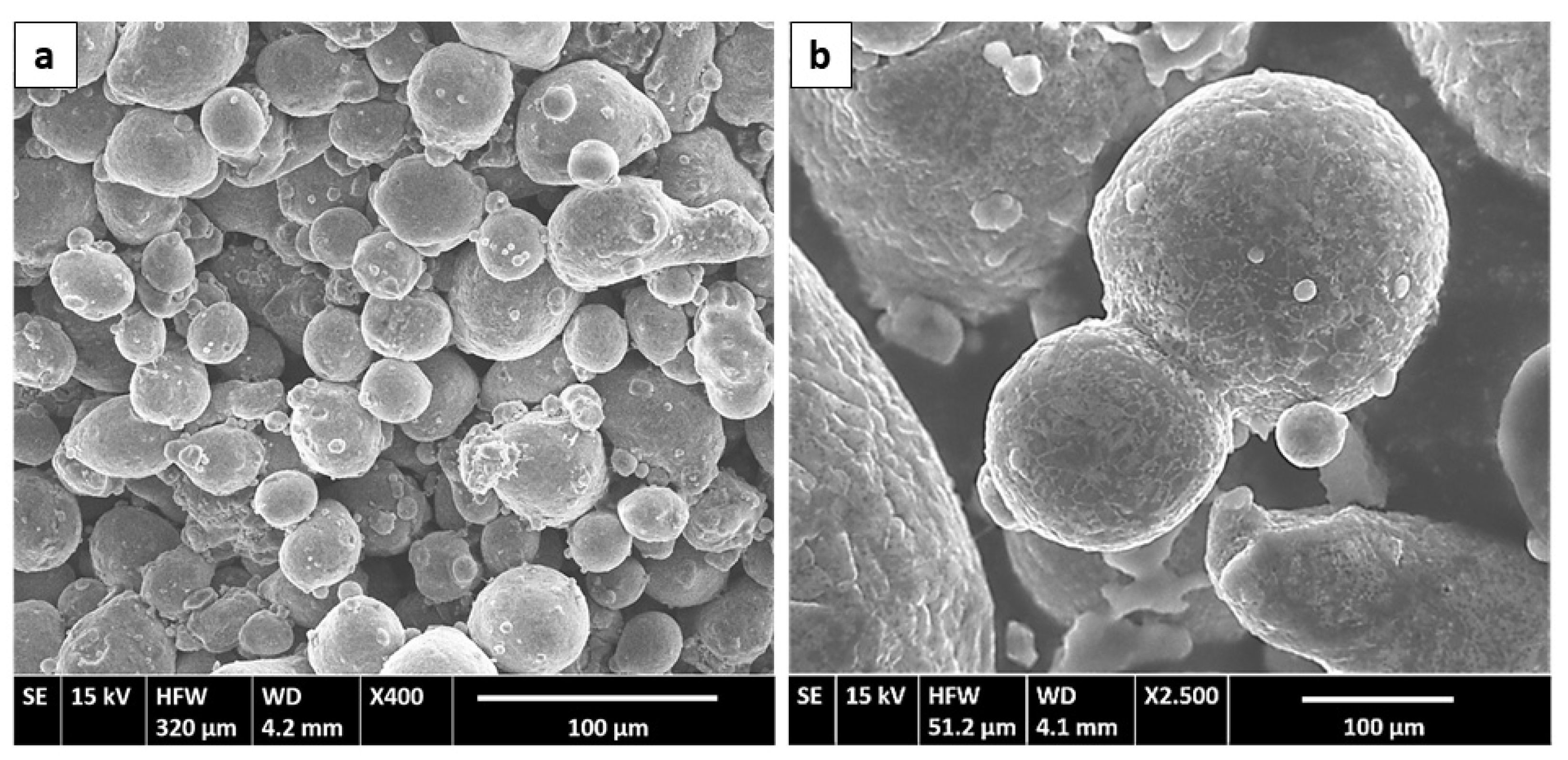
3.1. Characterization of Raw Materials

The SEM images of as-received AA 7075 powders show the typical morphology for the inert gas atomized powders (Figure 1a). Most of the small and medium diameter particles have a spherical shape, in contrast to the most irregular shape shown by the coarse particles. In addition, as is usual in powders obtained through this technique, many of the particles show a small number of satellites (Figure 1b). The particle size distribution of the as-received powders is depicted in Figure 2. An average grain size of 35.57 μm was determined.
The fine solidification microstructure of powder particles is illustrated in Figure 3. A combination of cellular and dendritic-like morphology [30] can be observed. The sizes of cells and dendrites ranged between 1 and 8 μm. Even when no precipitation of intermetallic phases was found in the interdendritic spaces of the examined particles, EDS determined a clear segregation of Mg, Zn and Cu, as well as O, along boundaries (Figure 4). The absence of intermetallic phases in the prealloyed powders was confirmed by XRD, as will be explained later on in this paper.
The strong tendencies of MWCNTs to form bundles and aggregate together, due to their high surface area and the strong Van der Waals interaction, makes their examination and characterization difficult [31]. MWCNTs are usually hydrophobic; therefore, without the addition of a surfactant, they are not readily dispersed in water, even under sonication. Organic solvents (for example, acetone, methanol, ethanol, toluene or chloroform), are commonly used. For the HRTEM study, ultrasonic stirring for 5 min produced a suspension of a small amount of carbon nanotubes in ethanol. After this time, a suitable homogenization of the suspension is obtained, and a droplet is deposited on the sample holder and, after evaporation, examined. Figure 5a shows bundles of MWCNTs that could not be adequately dispersed. That makes it difficult to verify the dimensions of the tubules. An average outer diameter (OD) between 10 and 20 nm, as indicated by the manufacturer technical data sheet, was estimated by 50 measurements made on the terminal tubules of different clusters (Figure 5b). A small fraction of nanotubes of OD > 30 nm has also been detected. Due to the degree of entanglement of MWCNTs, their average length was not verified.

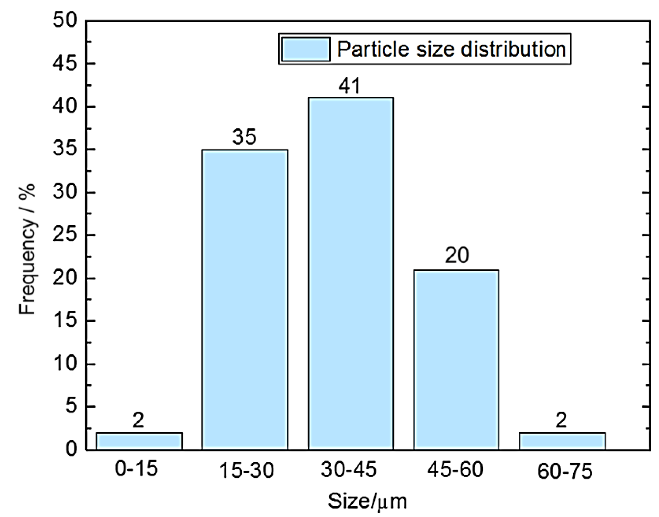
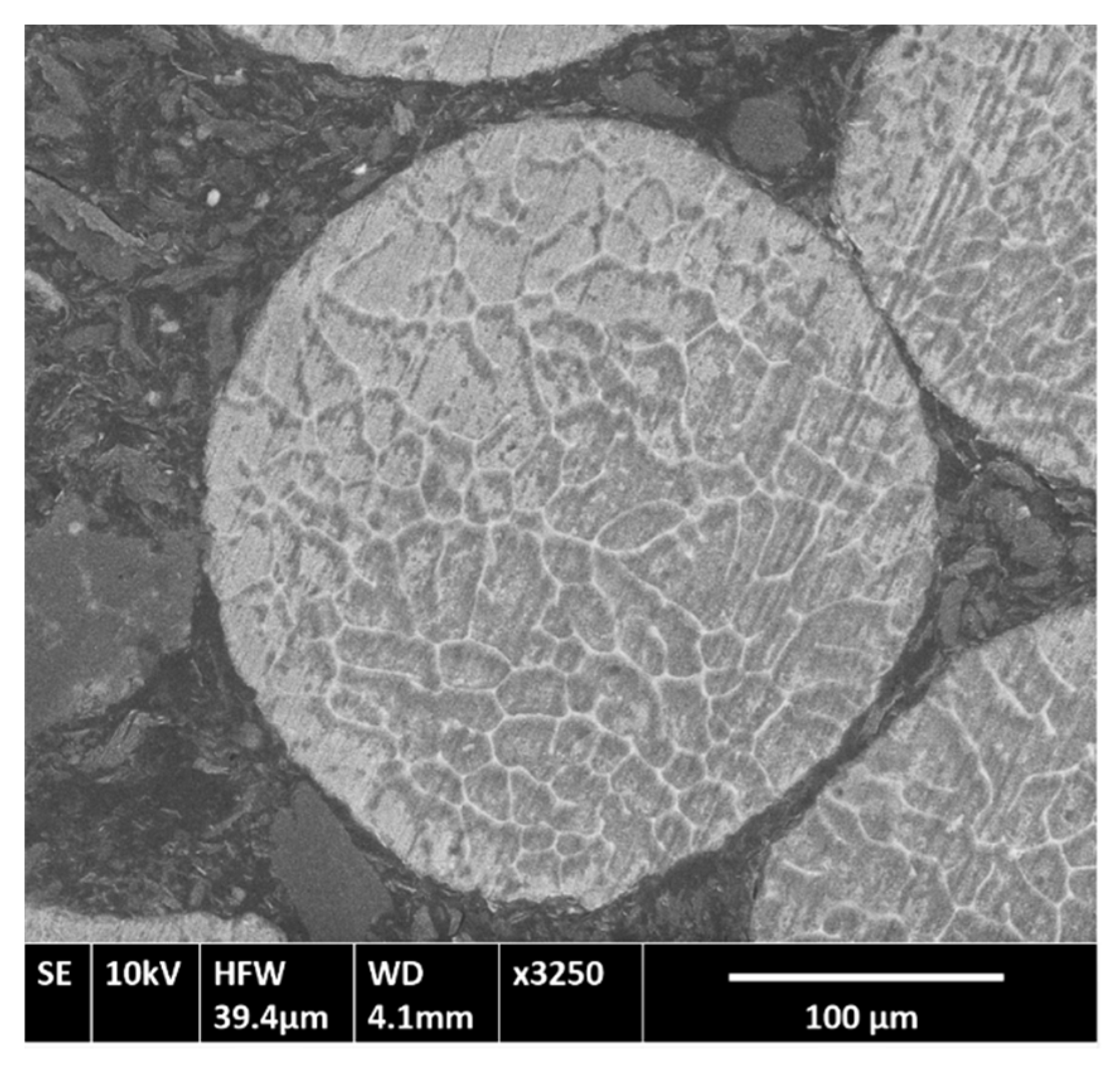
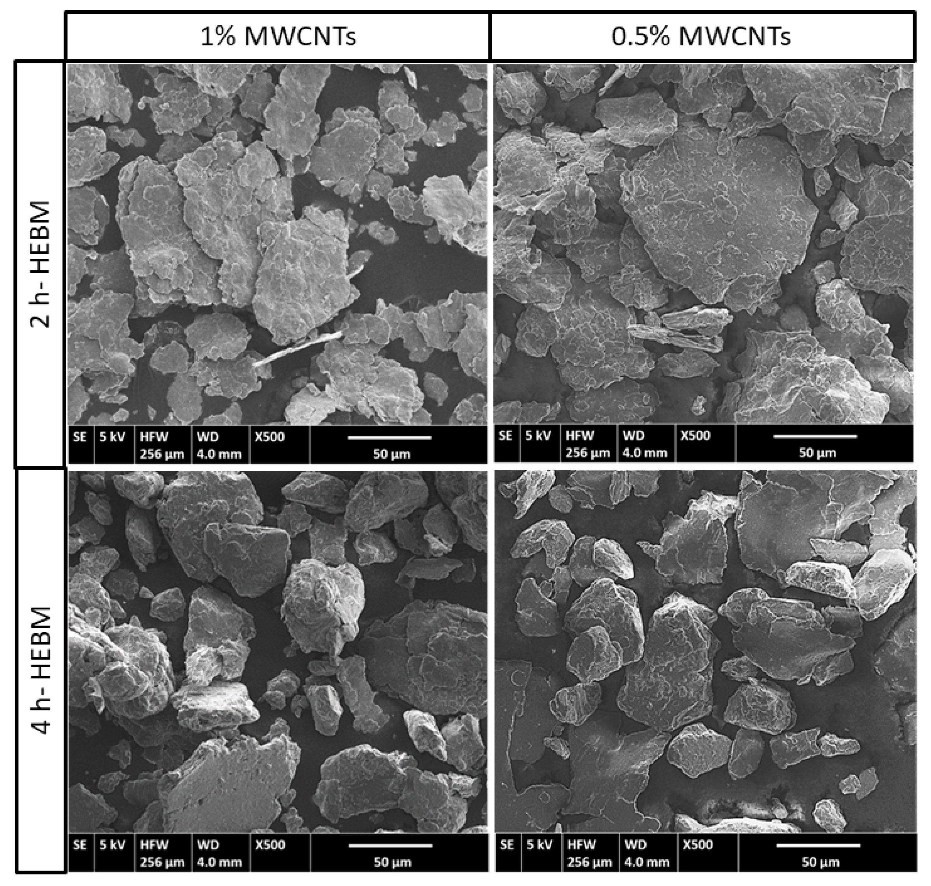
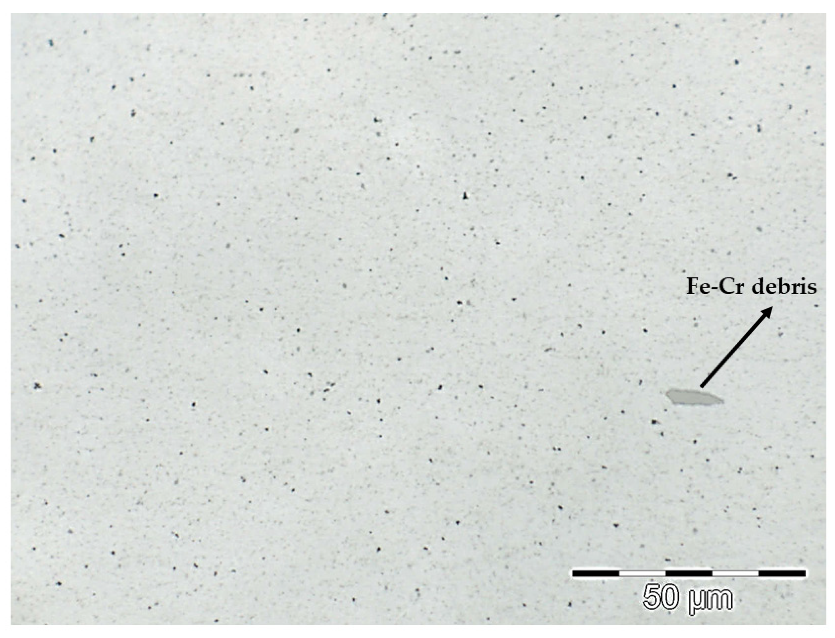
3.2. Morphology and Size of AA7075-MWCNTs Composites

The morphology of 0.5 wt.% and 1 wt.% MWCNTs composite powders ball-milled for 2 h and 4 h is represented in Figure 6, showing particles that are clearly irregular in shape. In the first two hours, under the high energy impacts of the balls, the initially spherical powder particles undergo a severe deformation, transforming into flakes. The cold welding of the flakes leads to the formation of large particles with a multilayer structure and a rough surface. With continued deformation, the particles become work-hardened and the eventual fracturing takes place, leading to a decrease in the particle size [32]. This effect is visible in both AA7075-MWCNTs composites after 4 h of HEBM and more intense in the 1 wt.% MWCNT powders.
To verify this effect, the particle size distributions obtained from powders with both reinforcement percentages after 2 h and 4 h of HWBM are represented in Figure 7. For both composites, most of the measured particles are in the 20–80 μm range after the initial two hours. At the completion of the total milling time, the percentage of particles with sizes ranging from 20 to 40 μm is greatly increased. The computed average particle size for 1 wt.% MWCNTs is close to 63 μm at 2 h and 54 μm after 4 h milling time. In the case of 0.5 wt.%, these values are 82.5 μm at 2 h, and 72.3 μm after completing the milling process.
This difference can be attributed to the effect of MWCNTs, which act as a process control agent by attaching to the surface of the particles, limiting cold welding and subsequently favouring more plastic deformation, thus interfering in the cycle of deformation–welding–fracture that each particle undergoes during HEBM. At the same time, MWCNTs are being incorporated to the matrix of the particles, producing harder surfaces at each impact from the milling media, and therefore increasing their brittleness [32,33]. With the increasing content of MWCNTs, the effect is maximized, leading to a lower average particle size [22].

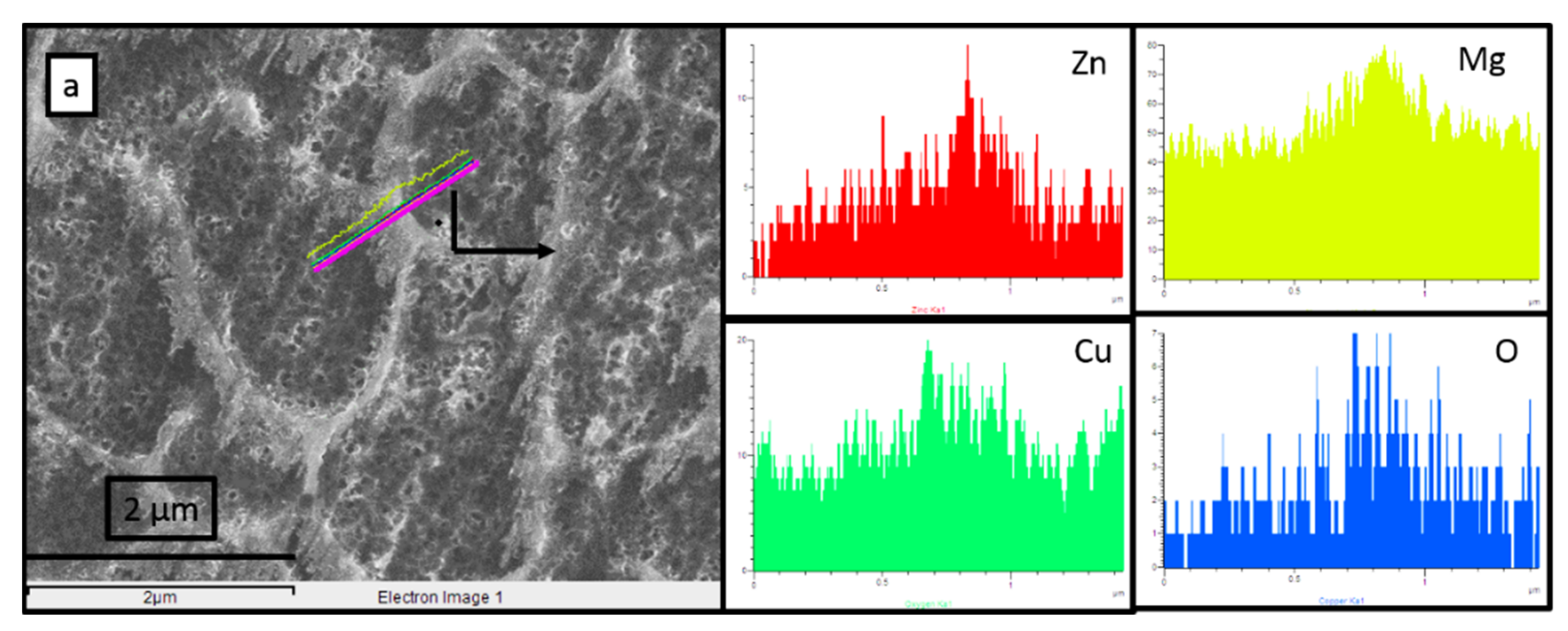
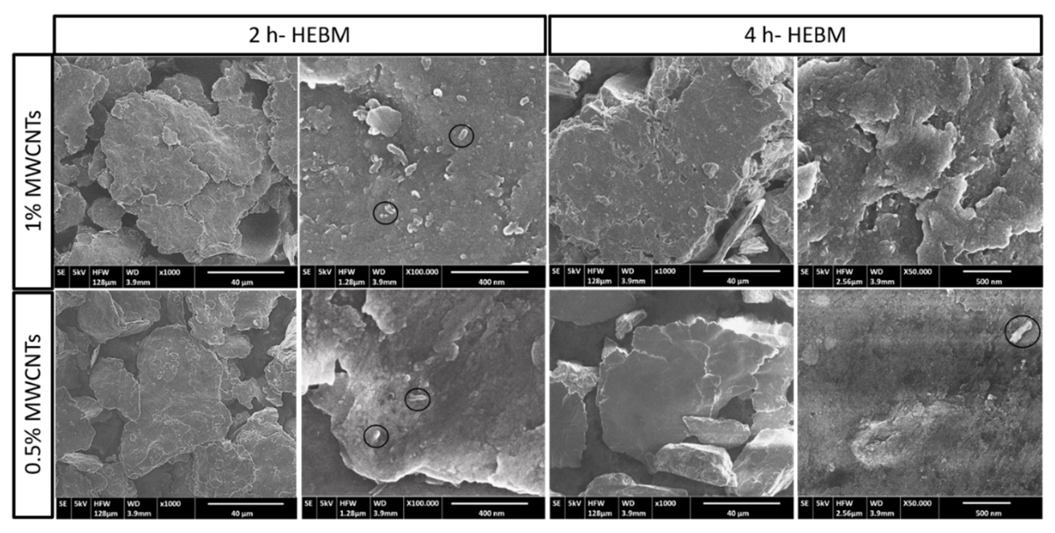
3.3. MWCNTs Dispersion in the Composite Powders

Detailed SEM observations of the particle surfaces after the two milling times were carried out to investigate the dispersion of the MWCNTs in the composite powders (Figure 8). Images show that, under the effect of the high energy ball-milling, the bundles of MWCNTs were gradually disentangled, separated and dispersed into the 7075 powders. After 2 h, the clusters adhere very uniformly on the surface of AA7075 particles, forming a thin and homogeneous layer in which only few tubules can be individually differentiated. Increasing the milling time up to 4 h, the surfaces of the particles have a very smooth appearance and almost no nanotubes can be observed on the surface. The absence of bundles or even disperse tubules of MWCNTs support the assumption that reinforcements are already embedded into the matrix particles. This occlusion is possible since the matrix powders are being deformed into flakes, therefore creating flat surfaces that can provide more sites for the adhesion of the tubules. After the cold welding of the particles into coarse powders, the MWCNTs fixed at the welded seams become trapped inside the powders. Fracturing creates new surfaces, and the process can continue until the particles become hard and the adhesion of new nanotubes finalizes [34]. This is the reason why no nanotubes are visible on the surface of the particles after 4 h milling.
Therefore, the homogenous dispersion of MWCNTs within the AA7075 matrix seems to be achieved in the proposed milling process. However, the effect of the high energy milling on the 7075 matrix and on the integrity of the nanotubes needs to be analysed.

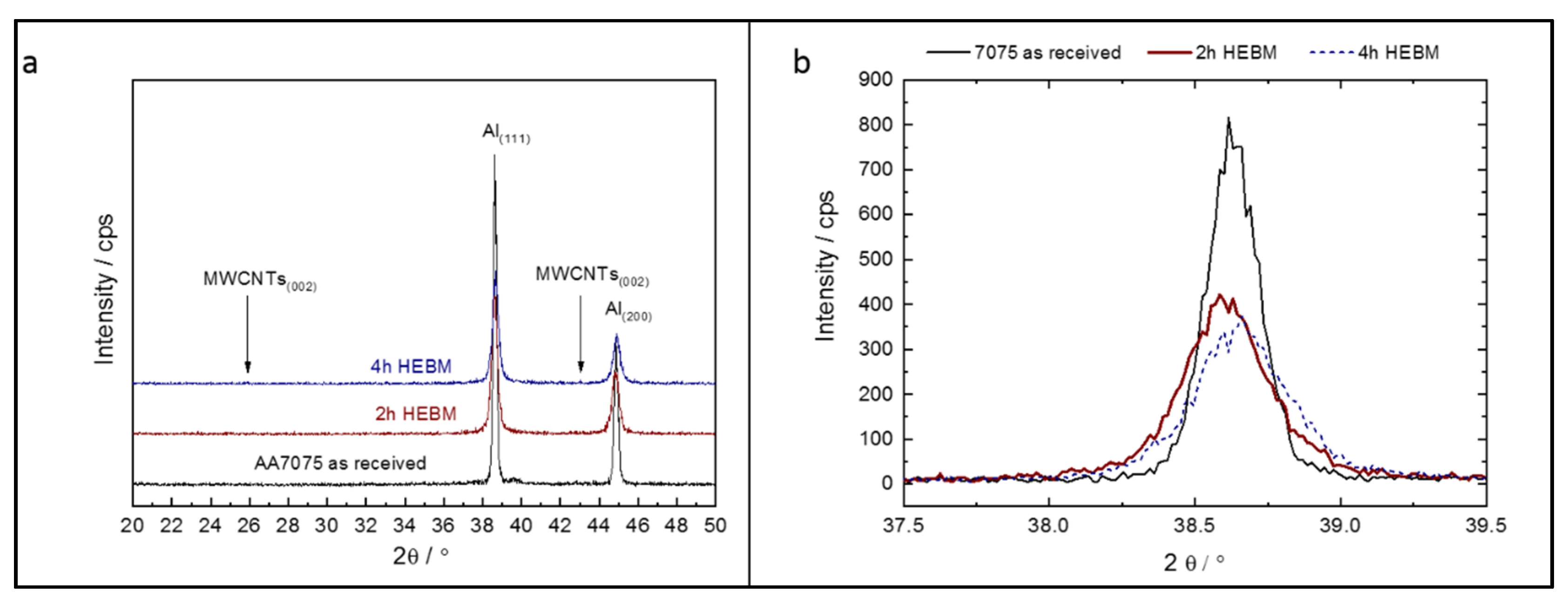
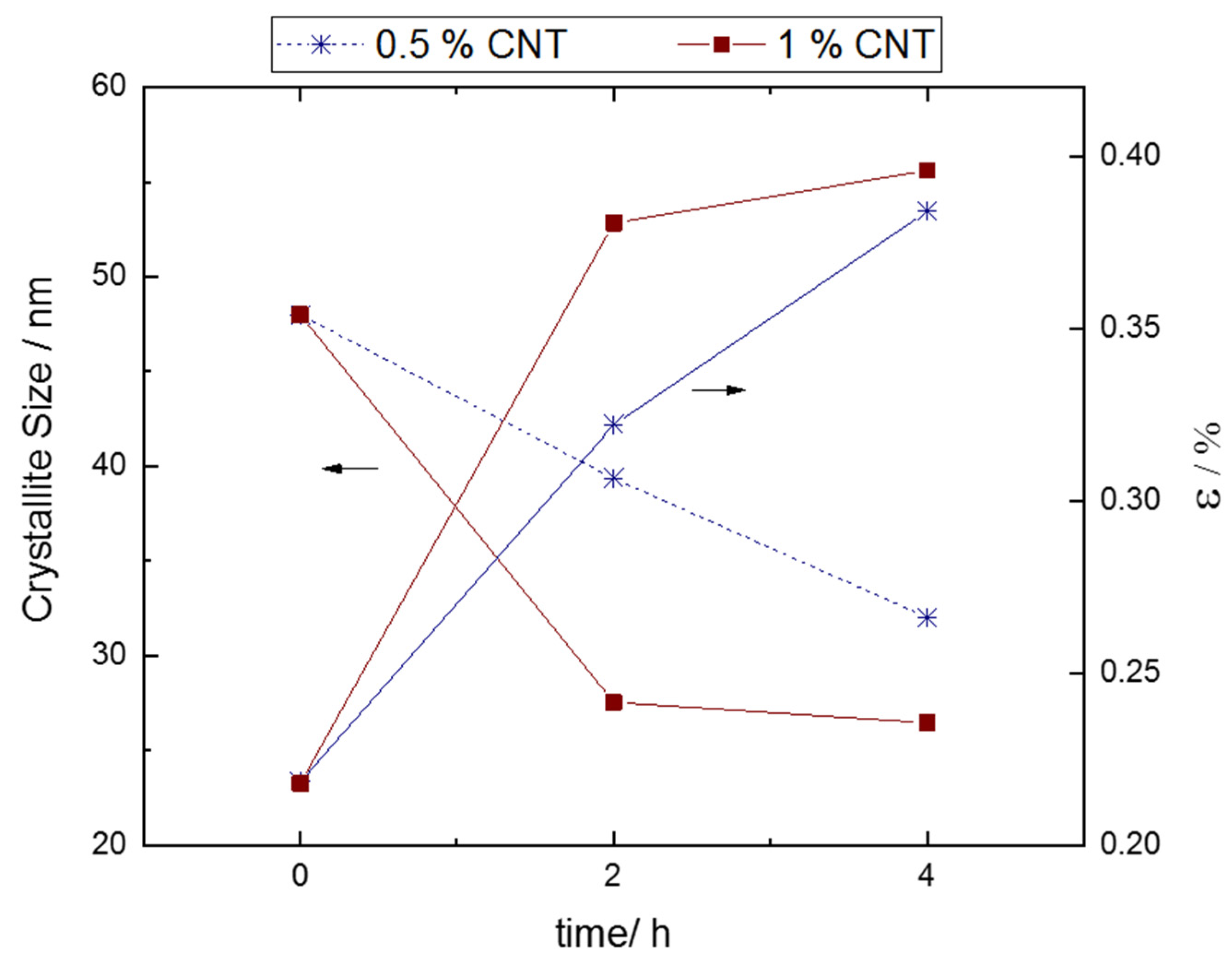
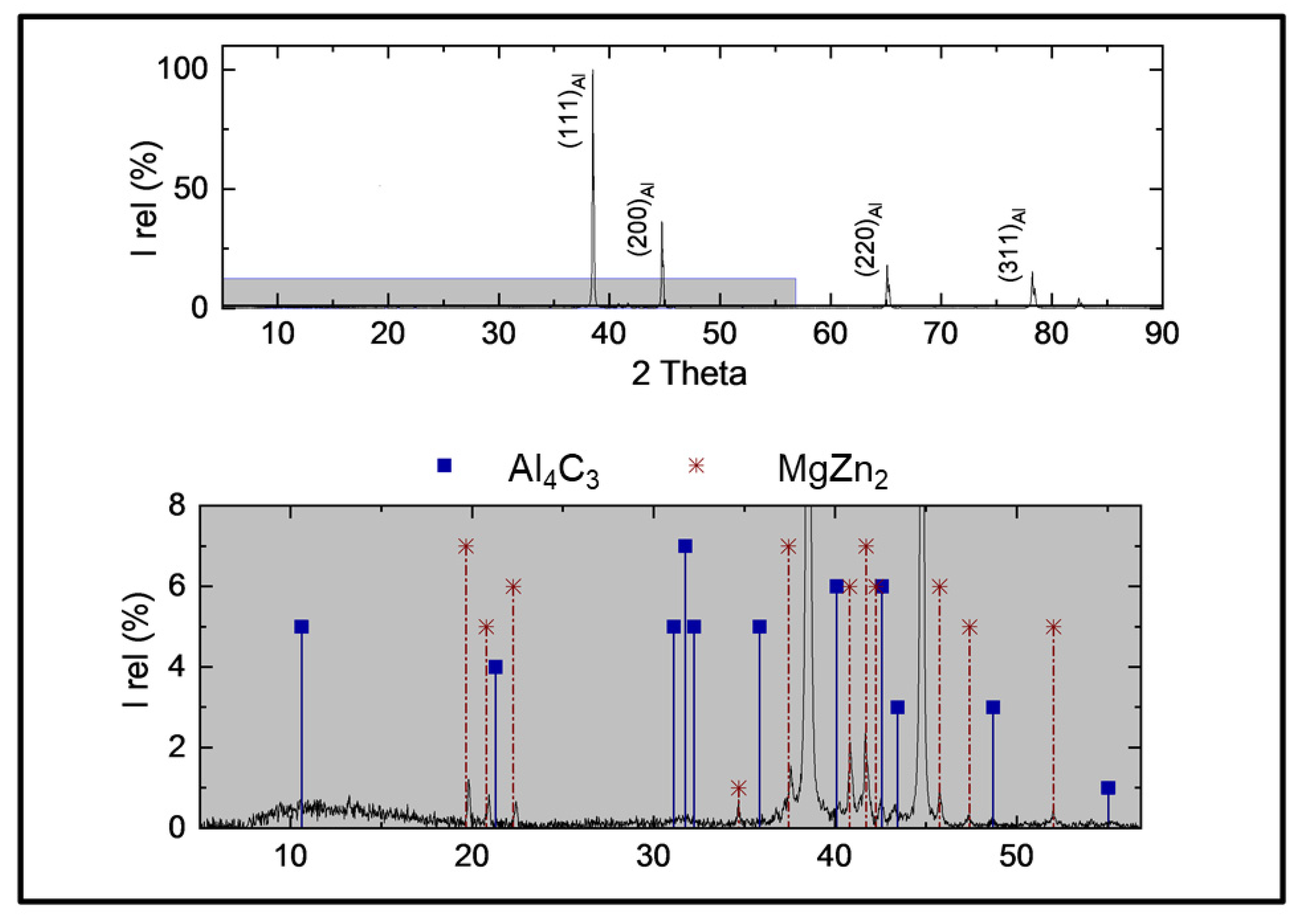
3.4. Effect of HEBM on Crystallite Size and Lattice Strain

The X-ray diffraction patterns of 7075-1 wt.% MWCNT composite powders milled for 2 h and 4 h are compared to those of the as-received AA7075 powders, as shown in Figure 9. Similar spectra are recorded for the 7075-0.5 wt.% MWCNT. Only the five major peaks corresponding to FCC phase of Al are observed. No discernible peaks related to the presence of nanotubes are detected. Some authors refer to the formation of small diffraction peaks at 2θ values close to 26° corresponding to (002) of graphite, attributed to the carbon nanotubes [35,36]. Esawi et al. [35] show that this peak disappears as the milling time is increased, due to the combination of the small amount of CNT, the good dispersion into the matrix, the increase in strain and the possible amorphization of the CNTs, which will contribute to reducing the peak intensity. Even when all those factors can be taken into account, in the present work, the lower proportion of MWCNTs used in the fabrication of the composites, which is clearly at or under the limit of the XRD resolution [37], is considered to be the main cause for the absence of the peaks.
Similarly, no peak is detected in the angle range of 30–37° that could be attributed to the formation of (Al4C3) during ball milling. This aluminium carbide, resulting from the thermodynamically favourable reaction between the MWCNT and the Al matrix, is commonly found in the composites fabricated through liquid metallurgy, due to the high temperatures involved. In powder metallurgy processing routes, the formation of Al4C3, to some extent, has also been reported [13,38,39]. In the ball milling stage, the reaction can occur not only as a consequence of the temperature reached, but also because of the creation of defect sites and open ends in the CNTs, which favour the formation of the aluminium carbide at local sites at temperatures well below the Al melting point. The absence of this signal in the obtained XRD patterns does not rule out the existence of the carbide but relates to a percentage less than the limit of detection.
An enlarged vision of the intense peak Al (111) in Figure 9b shows its evolution with milling time. A slight peak shift towards higher diffraction angles is produced from 2 h to 4 h. Several authors have previously reported a displacement in the position of the XRD aluminium peaks towards lower diffraction angles [40] or towards higher values [41], as results of the HEBM, for different aluminium composites. This shift is due to the dissolution of alloying elements and the effect of the reinforcement particles in the strain accumulation into the lattice of the aluminium matrix during milling.
A broadening of the full-width at half-maximum (βhkl) and a decrease in peak intensity is observed as milling time increases, indicating structural changes such as a reduction in crystallite size and an accumulation of heterogeneous micro-strain in the deformed powder particles [40,41,42].
In the as-received powders, an average crystallite size of 48 nm, and lattice strain of ε = 0.218% were calculated from the broadening of the (111) peak diffraction through the Scherrer equation. The variation in crystalline size and lattice strain of composite powders, as a function of milling time, are presented in Figure 10. The average crystallite size decreases significantly during early stage of HEBM for both MWCNT percentages, leading, in the first 2 h, to a crystallite refinement that, for the 7075-1 wt.% MWCNT composite, is close to 43%, but only 20% for the 7075-0.5 wt.% MWCNT.
It should be noted that the more intense decrease in crystallite size was achieved at significantly shorter times than those reported by other researchers [40] due to the higher energy involved in the milling process followed in this work, which was performed with the same BPR (10:1) in a cycle operation procedure at higher rotary speeds.
The high energy of the ball impacts during this first stage of milling, where the 7075 is still ductile and the lattice strain is low, induces severe plastic deformation, creating a large number of dislocations. Dislocations are rearranged to a lower energy state and low angle sub-boundaries are formed. As the generation of dislocations continues, low angle sub-boundaries turn into high angle boundaries and become grains at the nano scale. The presence of MWCNTs can also accelerate the grain refinement process by hindering the movement of dislocations by Orowan strengthening mechanism [40]. Concurrently, for each milling time, the micro-strain of alloyed matrix becomes higher due to the increase in dislocation density. This effect can be enhanced by the interaction of dislocations with solubilized atoms and MWCNTs leading to the rise in the strain accumulation in composite particles [43].
As a consequence of the strain hardening, the crystallite refinement produced in the following two milling hours is far less remarkable, leading to an overall decrease in crystallite size of 45%, from the initial one of as-received 7075 powders, in the 7075-1 wt.% MWCNT composite, and of nearly 35% in the 7075-0.5 wt.% MWCNT. The final size of crystallite determined for the 7075-1 wt.% MWCT was close to 26 nm and 32 nm for the 7075-0.5 wt.% MWCT composite. This difference is believed to result from the pinning effect of MWNTs on the grains, which is more effective as the percentage of reinforcement is increased [44].
An increase in the lattice strain from the initial 0.22% to 0.38% after 2 h and to 0.40% after 4 milling hours was observed for the 7075-1 wt.% MWCT powders. In the case of 7075-0.5 wt.% MWCNT, the value of the lattice strain after 2 h is 0.32%, and after 4 h is 0.38%.

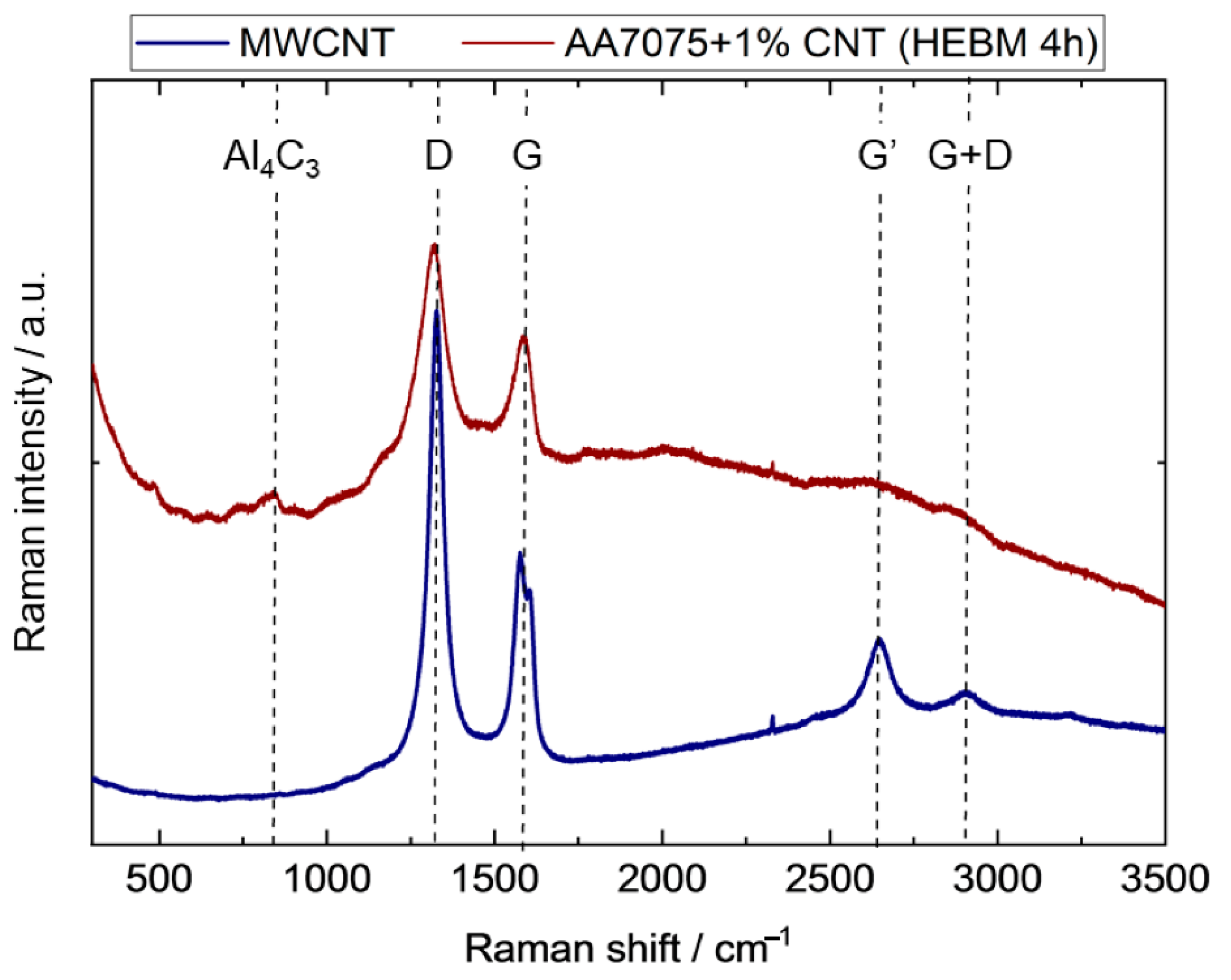
3.5. Effect of HEBM on the MWCNTs

To assess the damage induced to the structure of MWCNT during the ball milling, Raman spectroscopic measurements were carried out. This technique has been very useful at describing the structural properties of single wall carbon nanotubes (SWCNTs), yielding information about purity, tube alignment and defects. Recently, MWCNTs have been also characterized by Raman spectroscopy, but the interpretation is often more complex, usually based on the well-established results obtained for SWCNTs. Figure 11 depicts the Raman spectrum obtained on the as-received powder of bundled MWCNTs and the powders of 7075-1 wt.% MWCT after 4 h HEBM, under a 632.8 nm laser for 20 scans, with a total exposure time of 15 s. Similar results were obtained for the 0.5 wt.% composite. Three regions can be considered in these spectra:
In the 400–850 cm−1 region, the 7075-1 wt.% MWCT composite shows two small peaks at 488 cm−1 and 840 cm−1, already reported by Z.Y. Xu and coworkers [19]. These peaks are consistent with those found in the Raman spectra of Al4C3 [45]. The slight shift of several cm−1 between the reported values and those measured in this work can be attributed to crystal defects of the Al4C3 grown over the damaged MWCNTs. This fact is a confirmation of the formation of this carbide, although it was not detected by XRD.
The second region of the spectra displays the first order peaks composed of the D-band at around 1327 cm−1 and the G band at 1576 cm−1 in the as-received MWCNTs spectra. The G band is the only peak present in pure and perfect hexagonal graphite and corresponds to the tangential vibrations of the C-C sp2 bonds atoms. This band is usually composed of a double signal (G+ and G−) [31]; in this work, the G+ band is detected at 1576 cm−1 and corresponds to atomic displacements along the nanotube axis, while the G− band, at 1608 cm−1, is assigned to circumferential atomic displacements, and is, therefore, diameter dependent.
On the other hand, the D− band is assigned to the presence of disorder in C-C bonds or defects concentration in graphitic materials [31,45,46]. In MWCNTs, this carbon structural disorder has been attributed to the presence of defects as vacancies, kinks and heteroatoms, as well as finite or nanosized graphitic planes in rings [47].
In the spectra of the 7075-1 wt.% MWCT composite, a slight shift of the G band towards higher frequencies (1583 cm−1) after milling [17,48] and towards lower frequencies of the D band 1324 cm−1 is observed [49]. This effect, as well as the broadening of the peaks from the D and G bands, indicates the amorphization of the nanotubes, due to the partial destruction of the outer walls during HEBM and its corresponding transformation into amorphous carbon [49]. The deterioration of the walls of the tubules generates zones for the reaction of Al and C forming the Al4C3, whose presence was determined by the peaks at low frequencies.
A parameter usually used for assessing this damage is the change in the two band intensities, quantified by the ID/IG ratio. Table 2 shows the determined values for the MWCNTs and the milled 1 wt.%. composite, after removing background contribution. An increase of 44% in this ratio is obtained after the high energy milling due to the intense creation of defects in the nanotubes and, consequently, giving rise to an increase in the D band intensity and a reduction in the G band intensity [19,39,48].
Finally, the Raman spectrum of MWCNTs also exhibits a band at around 2650 cm−1 corresponding to a second-order harmonic of the D mode, denoted as G’ and considered as indicative of long-range order in a sample [31,39]. This band almost disappears in the 7075-1 wt.% MWCT composite, as an indication of a certain amorphization. The G+D band (~2920 cm−1) in MWCNTs spectrum, due to the presence of C-H bonds, is also distinguishable [39,49,50] in composites.

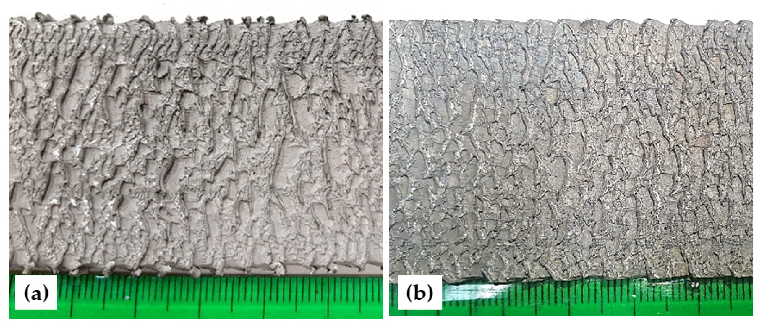
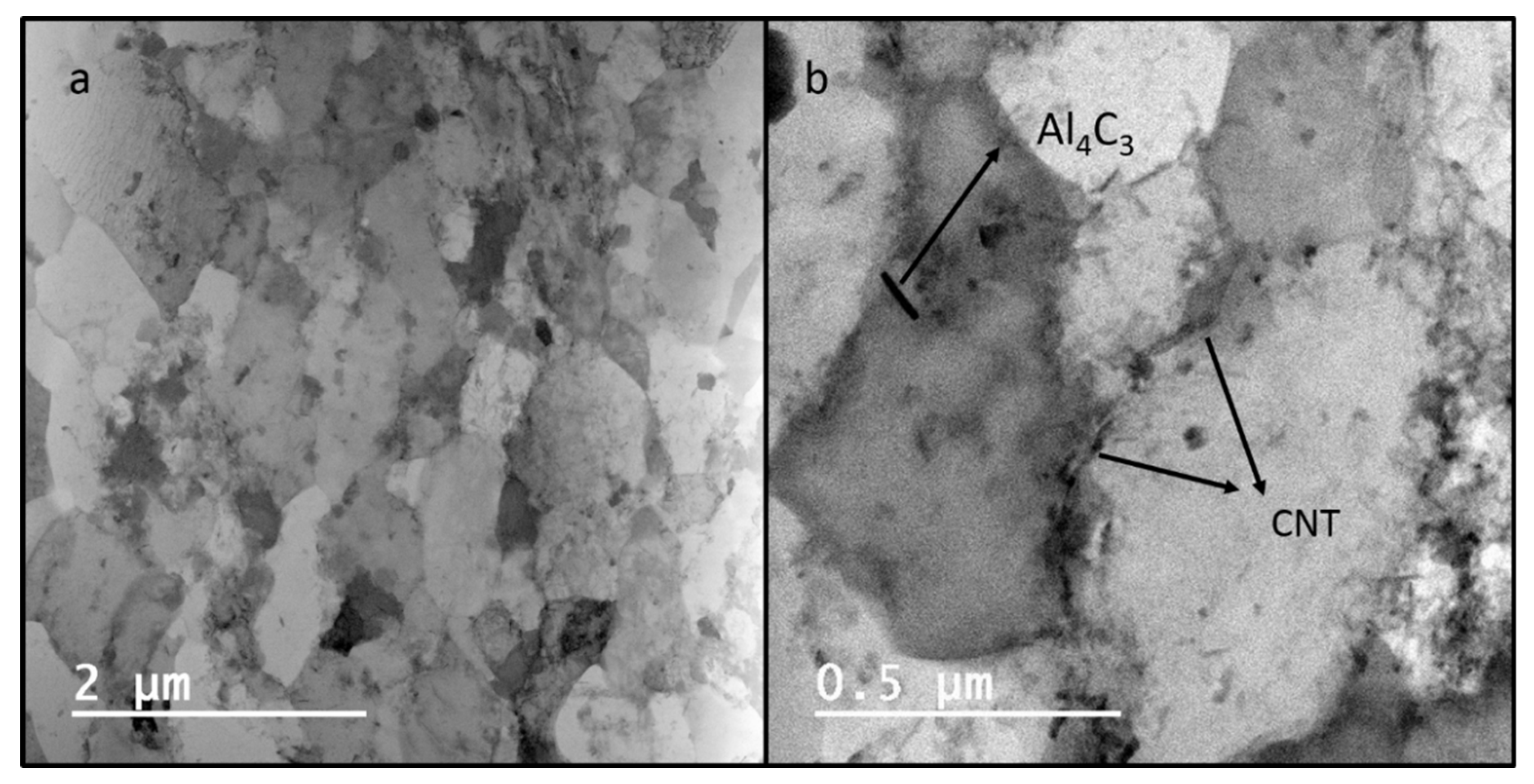
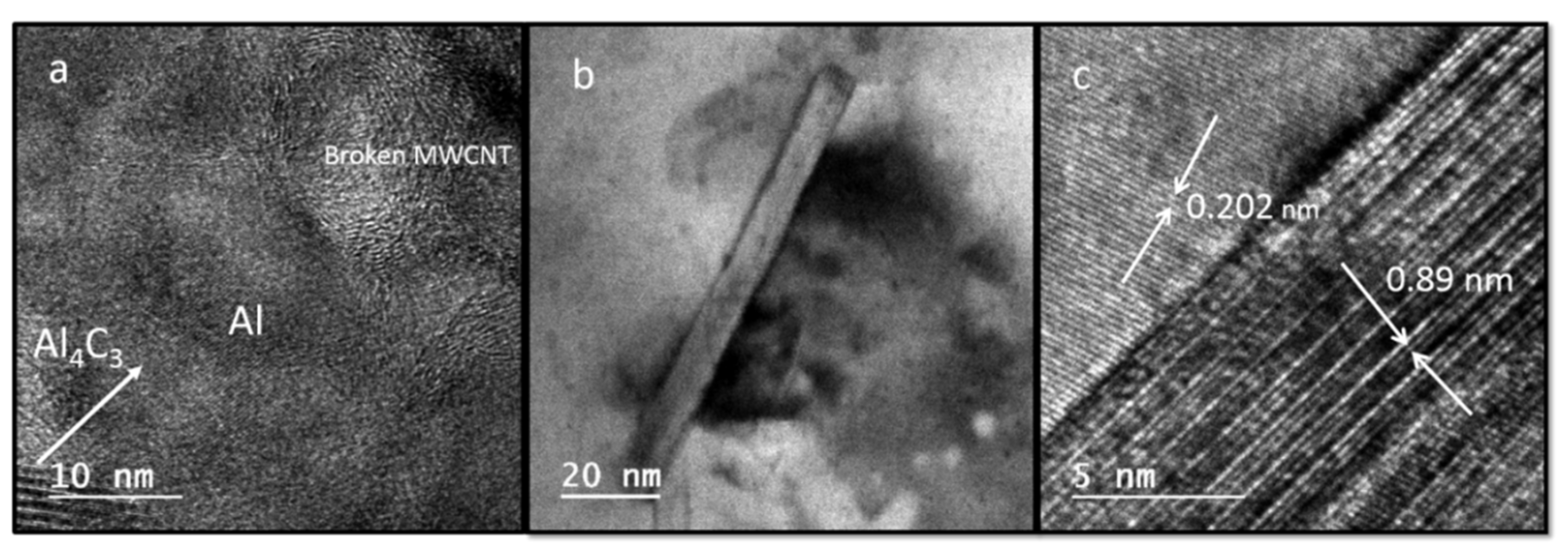
3.6. Characterization of the Extruded Profiles

After milling, the composite powders were compacted by compression, prior to extrusion. The degree of densification was not very high due to the smooth surface of the particles and the lubrication effect provided by MWCNTs. The extrusion was performed at 500 °C at a ram speed of 0.5 mm/s. Severe tearing defects are present on the surface of all the samples, being more intense on the profiles of 7075-1 wt.% MWCNT (Figure 12).
As is well known, AA7075 shows a low extrudability, requiring high extrusion pressure. In addition, due to its low solidus temperature, which can cause incipient melting, the hot extrusion of this alloy is limited by the onset of tearing appearance, characterized by the formation of severe cracks at the surface of the extruded profiles. Hot tearing is a type of failure that results from a sequence of phenomena consisting of local melting, crack formation and final fracture of the product, and depends on material characteristics, but also on process variables. From the literature review, it is clear that Al-Mg-Zn-Cu eutectic phases [51,52] located at the dendrite boundaries are especially detrimental. In addition, the microsegregation of Mg, Cu and especially Zn has been reported to sharply decrease the local melting point, thereby encouraging tearing sensitivity [53,54]. Therefore, to avoid hot tearing on this alloy, the extrusion speed is usually kept very low, especially in high-temperature conditions.
In the present work, the selected ram speed was very low (0.5 mm/s), but even in this condition the tearing appearance of the surface is very intense, especially in the 7075-1 wt.% MWCNT composite.
As it was previously indicated, the SEM-EDS and XRD study on the as-received 7075 powders demonstrated the absence of any intermetallic phase but showed a relevant microsegregation of alloying elements at the dendrite boundaries. Due to the high energy of the ball milling process, the composite matrix is far from equilibrium conditions and during the heating stage prior to extrusion, precipitation of intermetallic phases can take place. This precipitation can lead to an increase in the hot tearing sensitization of the alloy.
In subsequent works, the extrusion temperature will be reduced to avoid the formation of this surface defect.
Despite the inadequate surface appearance, the full densification of the composite is achieved after hot extrusion (Figure 13). No pores or cracks were detected in the detailed microscopic examination performed in specimens extracted from the extruded profiles at longitudinal and transversal sections.
The contamination with Fe-based wear debris from the milling tools is very common in materials prepared by high-energy ball milling synthesis route. The presence of these particles is a major concern that is not always reported. In this work, only a few scattered Fe-Cr inclusions were detected, with variable morphology and size, showing a good particle–matrix adhesion. However, a slight accumulation of nanotubes tends to occur at this matrix–particle interface.
The microscopic exam reveals the good dispersion of MWCNT bundles (small grey spots, as shown in in Figure 13, that are homogeneously distributed throughout the matrix) and the presence of small intermetallic phases in the matrix, which are not well identified in the microscopic exam. As already indicated, the precipitation of these phases could take place in the heating stage prior to the extrusion of the material.
The XRD analysis performed in both extruded composites (1 wt.% and 0.5 wt.% reinforcement) confirmed the presence of MgZn2 intermetallic phases, as well as the Al4C3, as Figure 14 shows for the 7075-1 wt.% MWCNT.
As can be seen on the low-magnification TEM images, depicted in Figure 15, a very fine-grained and homogeneous microstructure is developed after milling and extrusion; however, it also becomes evident that the entangled nanotubes have not been properly individualized, but have instead dispersed and formed fine clusters throughout the matrix. The homogeneity in the distribution of these clusters throughout the mass of the composite material is comparable to that obtained by other authors after longer milling times in 6061Al–matrix composites [55] or using combined strategies in 7075-CNTs [23].
Long and entangled nanotubes are accumulated at the limits of scattered and small grains regions. The presence of these bundles seems to exert a pinning effect on the grain boundaries, limiting the growth of the grains during the recrystallization process (Figure 15b) [13,19]. Therefore, even when these clusters contribute to the formation of finer grains, greater heterogeneity in the general grain microstructure is derived (Figure 15a).
Figure 15b also reveals that MWCNTs can be singly dispersed and integrated in the 7075 matrix, randomly located at grain boundaries and inside the grains. These nanotubes are shorter than the as-received ones due to the severe shear effect during high energy milling [34]. HRTEM images show that these short MWCNTs are fully integrated in the aluminium matrix (Figure 16a).
The presence of small amounts of Al4C3 nanorods, with lengths of between 50 and 80 nm, was verified (Figure 16b) [19]. These particles, previously detected in Raman spectra, were formed from the reaction between MWCNTs that were shortened and damaged in the HEBM and the matrix.

3.7. Mechanical Properties of Composites

Table 3 shows the average mechanical properties of 7075-MWCNTs composites. The average HV0.2 values obtained on the specimens extracted from the extruded profiles in the longitudinal and transverse directions are compared to the values measured in a conventional 7075 alloy (in O condition) and in T6 condition.
As it was expected, by comparison with conventional AA 7075-O, a substantial increase in hardness is measured (more than 80%), and the increase in MWNTs concentration from 0.5 wt.% to 1 wt.% leads to a rise of almost 5% in the hardness of the composite. These results are similar [22] or even clearly superior [23] to those reported previously by other researchers in 7075 composites with similar weight percentages of MWCNTs. As with these cases, the increase in wt.% induces an increment in hardness. However, while in the mentioned papers, the tensile properties also showed an improvement with the increase in the reinforcement amount (until a maximum value of 1 wt.% [23] or 2 wt.% MWCNTs [22]), in our case, the best tensile behaviour is obtained with 0.5 wt.% MWCNTs.
For this reinforcement fraction, the obtained yield strength is 377 MPa, a value clearly higher than that presented in the aforementioned papers, which represents an improvement of more than 260% compared to AA7075. Jagannatham et al. [23] reported a maximum value of yield strength of 215.21 MPa at 1 wt.% CNTs, while Uriza-Vega et al. [22] obtained yield strengths for 0.5 wt.% and 1 wt.% lower than that of AA7075. Similarly, the measured average tensile strength for the 7075-0.5 wt.% MWCNTs is 436MPa, representing a 91% enhancement by comparison with conventional AA 7075.
The improvement of mechanical properties is affected by four factors [13,56]: the matrix strength (mainly due to grain refining and solid solution), the interface reaction, the dispersion of MWCNTs and the damage of MWCNTs. On the one hand, the high energy involved in the milling stage used in the fabrication of the 0.5 wt.% and 1 wt.% composites produced an important grain size reduction, which, despite not being completely homogeneous after extrusion, helped to significantly increase the matrix strength. In addition, the precipitation of intermetallic phases can play a role in the increase in strength measured. In the same way, the proposed milling stage produced a tight bonding between MWCNTs and the Al matrix, allowing the achievement of a high enhancement of the yield strength and ultimate strength.
However, the values obtained in the present research do not yet make it possible to achieve the excellent mechanical properties produced after precipitation hardening treatment to the T6 condition. Further improvements are currently being explored on the path to achieve this goal.
On the other hand, due to the high energy of this stage, significant damage in the MWNTs is expected, as the high ID/IG ratio obtained from the Raman spectra indicated. An initial effect of this damage can be the shortening of the nanotubes. If it were very intense, the aspect ratio of nanotubes could become smaller and the load transfer from the matrix could be affected, resulting in reduced mechanical properties of the CNT/Al composites [57]. In this work, the TEM observations, as well as the obtained mechanical results, confirm that deterioration of MWCNTs has not been so important. The second effect of the induced damage in MWCNTs can be the reaction at the surface of nanotubes to form in situ Al4C3 nanorods, which was effectively confirmed by TEM. Even when the formation of this carbide needs to be avoided, it has nevertheless been proposed as a way to further increase the hardness and strength of composites [19], but can also severely deteriorate the ductility of the composites.
Finally, the dispersion of MWCNTs and the uniformity in their distribution is not fully accomplished after 4 h of milling; therefore, a further increase in tensile resistance can be expected by improving this factor.
The decrement in the elongation properties of the composites is related to the increase in hardness and strength; however, it is reported that the more important factor affecting the ductility of the MWCNTs is the agglomeration of the nanotubes [23]. MWCNTs are more homogeneously dispersed in the 7075-0.5 wt.% MWCNT. This explains why its ductility is five times higher than that of 7075-1 wt.% MWCNT, even though its mechanical properties are only slightly greater.

4. Conclusions

Composites from AA7075 reinforced with 0.5 wt.% and 1 wt.% MWCNTs were successfully prepared by a powder metallurgy, using a high energy ball milling procedure, in which the rotary speed was varied between 1300 and 1000 rpm, followed by a hot extrusion process at 500 °C.
The high energy ball milling produced a decrease in crystallite size of 45% in the 7075-1 wt.% MWCNT composite and of nearly 35% in the 7075-0.5 wt.% MWCNT, compared to the as-received 7075 powders.
After hot extrusion, the obtained profiles showed full dense microstructure with a homogeneous distribution of reinforcements. The formation of a small amount of Al4C3 nanorods was confirmed, by TEM and XRD, as a consequence of the reaction between MWCNTs and the Al of the matrix.
The mechanical properties of the composites were determined, with the best combination of hardness, strength and ductility obtained in the 7075-0.5 wt.% MWCNT composite. This material shows an enhancement of more than 80% in hardness, 260% in yield strength, and 91% in tensile strength, by comparison with conventional AA 7075, combined with a 10% elongation. The difference in strength and ductility between the composites produced with both wt.% of reinforcement can be explained by the more homogeneous distribution of MWCNTs in the 0.5 wt.% composite.
One aspect to be improved is the surface aspect of the profiles, due to the appearance of hot tearing produced by the hot extrusion at 500 °C.

Author Contributions

Conceptualization, I.F. and M.C.; Data curation, I.F.; Formal analysis, M.C., M.J.C. and P.R.; Funding acquisition, G.P. and M.J.C.; Investigation, I.F., G.P., M.C., M.J.C. and P.R.; Methodology, I.F.; Project administration, G.P.; Supervision, G.P. and M.J.C.; Writing—original draft, G.P.; Writing—review & editing, G.P. All authors have read and agreed to the published version of the manuscript.

Funding

This research was funded by the Ministry of Science, Innovation and Universities and the European Regional Development Fund ERDF (Grant number: MAT2017-83825-C4-2-R).

Data Availability Statement

Not applicable.

Acknowledgments

The authors express their gratitude to Marcela Lieblich (CENIM) for her collaboration in the design and development of extrusions of composite materials.

Conflicts of Interest

The authors declare no conflict of interest.

References

  1. Eatemadi, A.; Daraee, H.; Karimkhanloo, H.; Kouhi, M.; Zarghami, N.; Akbarzadeh, A.; Abasi, M.; Hanifehpour, Y.; Joo, S.W. Carbon nanotubes: Properties, synthesis, purification, and medical applications. Nanoscale Res. Lett. 2014, 9, 393. [Google Scholar] [CrossRef] [Green Version]
  2. Tjong, S.C. Structural and mechanical properties of polymer nanocomposites. Mater. Sci. Eng. R Rep. 2006, 53, 73–197. [Google Scholar] [CrossRef]
  3. Yu, M.-F.; Lourie, O.; Dyer, M.J.; Moloni, K.; Kelly, T.F.; Ruoff, R.S. Strength and Breaking Mechanism of Multiwalled Carbon Nanotubes Under Tensile Load. Science 2000, 287, 637–640. [Google Scholar] [CrossRef] [Green Version]
  4. Coleman, J.N.; Khan, U.; Gun’Ko, Y.K. Mechanical Reinforcement of Polymers Using Carbon Nanotubes. Adv. Mater. 2006, 18, 689–706. [Google Scholar] [CrossRef]
  5. Esawi, A.; Morsi, K. Dispersion of carbon nanotubes (CNTs) in aluminum powder. Compos. Part A Appl. Sci. Manuf. 2007, 38, 646–650. [Google Scholar] [CrossRef]
  6. Kim, K.T.; Cha, S.I.; Hong, S.H.; Hong, S.H. Microstructures and tensile behavior of carbon nanotube reinforced Cu matrix nanocomposites. Mater. Sci. Eng. A 2006, 430, 27–33. [Google Scholar] [CrossRef]
  7. Kuzumaki, T.; Miyazawa, K.; Ichinose, H.; Ito, K. Processing of Carbon Nanotube Reinforced Aluminum Composite. J. Mater. Res. 1998, 13, 2445–2449. [Google Scholar] [CrossRef]
  8. Kwon, H.; Estili, M.; Takagi, K.; Miyazaki, T.; Kawasaki, A. Combination of hot extrusion and spark plasma sintering for producing carbon nanotube reinforced aluminum matrix composites. Carbon 2009, 47, 570–577. [Google Scholar] [CrossRef]
  9. Noguchi, T.; Magario, A.; Fukazawa, S.; Shimizu, S.; Beppu, J.; Seki, M. Carbon Nanotube/Aluminium Composites with Uniform Dispersion. Mater. Trans. 2004, 45, 602–604. [Google Scholar] [CrossRef] [Green Version]
  10. Liao, J.; Tan, M.-J. A simple approach to prepare Al/CNT composite: Spread–Dispersion (SD) method. Mater. Lett. 2011, 65, 2742–2744. [Google Scholar] [CrossRef]
  11. Morsi, K.; Esawi, A.; Lanka, S.; Sayed, A.; Taher, M. Spark plasma extrusion (SPE) of ball-milled aluminum and carbon nanotube reinforced aluminum composite powders. Compos. Part A Appl. Sci. Manuf. 2010, 41, 322–326. [Google Scholar] [CrossRef]
  12. Esawi, A.; Morsi, K.; Sayed, A.; Taher, M.; Lanka, S. Effect of carbon nanotube (CNT) content on the mechanical properties of CNT-reinforced aluminium composites. Compos. Sci. Technol. 2010, 70, 2237–2241. [Google Scholar] [CrossRef]
  13. Liu, Z.; Xu, S.; Xiao, B.; Xue, P.; Wang, W.; Ma, Z. Effect of ball-milling time on mechanical properties of carbon nanotubes reinforced aluminum matrix composites. Compos. Part A Appl. Sci. Manuf. 2012, 43, 2161–2168. [Google Scholar] [CrossRef]
  14. Perez-Bustamante, R.; Gómez-Esparza, C.; Estrada-Guel, I.; Miki-Yoshida, M.; Licea-Jiménez, L.; Pérez-García, S.; Sánchez, R.M. Microstructural and mechanical characterization of Al–MWCNT composites produced by mechanical milling. Mater. Sci. Eng. A 2009, 502, 159–163. [Google Scholar] [CrossRef]
  15. Kwon, H.; Leparoux, M. Hot extruded carbon nanotube reinforced aluminum matrix composite materials. Nanotechnology 2012, 23, 415701. [Google Scholar] [CrossRef] [PubMed]
  16. Esawi, A.; Morsi, K.; Sayed, A.; Taher, M.; Lanka, S. The influence of carbon nanotube (CNT) morphology and diameter on the processing and properties of CNT-reinforced aluminium composites. Compos. Part A Appl. Sci. Manuf. 2011, 42, 234–243. [Google Scholar] [CrossRef]
  17. Choi, H.; Shin, J.; Bae, D. The effect of milling conditions on microstructures and mechanical properties of Al/MWCNT composites. Compos. Part A Appl. Sci. Manuf. 2012, 43, 1061–1072. [Google Scholar] [CrossRef]
  18. Esawi, A.M.; El Borady, M.A. Carbon nanotube-reinforced aluminium strips. Compos. Sci. Technol. 2008, 68, 486–492. [Google Scholar] [CrossRef]
  19. Xu, Z.Y.; Li, C.J.; Li, K.R.; Yi, J.H.; Tang, J.J.; Zhang, Q.X.; Liu, X.Q.; Bao, R.; Li, X. Carbon nanotube-reinforced aluminum matrix composites enhanced by grain refinement and in situ precipitation. J. Mater. Sci. 2019, 54, 8655–8664. [Google Scholar] [CrossRef]
  20. Ogawa, F.; Yamamoto, S.; Masuda, C. Strong, ductile, and thermally conductive carbon nanotube-reinforced aluminum matrix composites fabricated by ball-milling and hot extrusion of powders encapsulated in aluminum containers. Mater. Sci. Eng. A 2018, 711, 460–469. [Google Scholar] [CrossRef]
  21. Jagannatham, M.; Chandran, P.; Sankaran, S.; Haridoss, P.; Nayan, N.; Bakshi, S.R. Tensile properties of carbon nanotubes reinforced aluminum matrix composites: A review. Carbon 2020, 160, 14–44. [Google Scholar] [CrossRef]
  22. Uriza-Vega, E.; Carreño-Gallardo, C.; López-Meléndez, C.; Cuadros-Lugo, E.; Pérez-Bustamante, R.; Ledezma-Sillas, E.; Herrera-Ramirez, J.M. Mechanical Behavior of Multiwalled Carbon Nanotube Reinforced 7075 Aluminum Alloy Composites Prepared by Mechanical Milling and Hot Extrusion. Mater. Res. 2019, 22, 652. [Google Scholar] [CrossRef]
  23. Jagannatham, M.; Saravanan, M.S.S.; Sivaprasad, K.; Babu, S.P.K. Mechanical and Tribological Behavior of Multiwalled Carbon Nanotubes-Reinforced AA7075 Composites Prepared by Powder Metallurgy and Hot Extrusion. J. Mater. Eng. Perform. 2018, 27, 5675–5688. [Google Scholar] [CrossRef]
  24. Zhang, H.; Wang, B.; Zhang, Y.; Li, Y.; He, J. Influence of aging treatment on the microstructure and mechanical properties of CNTs/7075 Al composites. J. Alloys. Compd. 2020, 814, 152357. [Google Scholar] [CrossRef]
  25. Sun, G.; Liu, Z.; Chen, G. DISPERSION OF PRISTINE MULTI-WALLED CARBON NANOTUBES IN COMMON ORGANIC SOLVENTS. Nano 2010, 5, 103–109. [Google Scholar] [CrossRef]
  26. Cabeza, M.; Merino, P.; Rey, P.; Román, M. Development of a high wear resistance aluminium matrix nanoreinforced composite. Surf. Interface Anal. 2012, 44, 1005–1008. [Google Scholar] [CrossRef]
  27. Kim, Y.D.; Chung, J.Y.; Kim, J.; Jeon, H. Formation of nanocrystalline Fe–Co powders produced by mechanical alloying. Mater. Sci. Eng. A 2000, 291, 17–21. [Google Scholar] [CrossRef]
  28. Srinivasan, R.; Yogamalar, N.R.; Joseyphus, R.J.; Bose, A.C. Estimation of lattice strain, stress, energy density and crystallite size of the spherical yttrium oxide nanoparticles. Funct. Mater. Lett. 2009, 2, 131–134. [Google Scholar] [CrossRef]
  29. Alexander, L.; Klug, H.P. Determination of Crystallite Size with the X-Ray Spectrometer. J. Appl. Phys. 1950, 21, 137–142. [Google Scholar] [CrossRef] [Green Version]
  30. Molnárová, O.; Málek, P.; Lukáč, F.; Chráska, T. Spark Plasma Sintering of a Gas Atomized Al7075 Alloy: Microstructure and Properties. Materials 2016, 9, 1004. [Google Scholar] [CrossRef] [PubMed] [Green Version]
  31. Lehman, J.H.; Terrones, M.; Mansfield, E.; Hurst, K.E.; Meunier, V. Evaluating the characteristics of multiwall carbon nanotubes. Carbon 2011, 49, 2581–2602. [Google Scholar] [CrossRef]
  32. Suryanarayana, C. Mechanical alloying and milling. Prog. Mater. Sci. 2001, 46, 1–184. [Google Scholar] [CrossRef]
  33. Morsi, K.; Esawi, A. Effect of mechanical alloying time and carbon nanotube (CNT) content on the evolution of aluminum (Al)–CNT composite powders. J. Mater. Sci. 2007, 42, 4954–4959. [Google Scholar] [CrossRef]
  34. Liu, Z.; Xiao, B.; Wang, W.; Ma, Z. Modelling of carbon nanotube dispersion and strengthening mechanisms in Al matrix composites prepared by high energy ball milling-powder metallurgy method. Compos. Part A Appl. Sci. Manuf. 2017, 94, 189–198. [Google Scholar] [CrossRef]
  35. Esawi, A.; Morsi, K.; Sayed, A.; Gawad, A.A.; Borah, P. Fabrication and properties of dispersed carbon nanotube–aluminum composites. Mater. Sci. Eng. A 2009, 508, 167–173. [Google Scholar] [CrossRef]
  36. Choi, H.; Kwon, G.; Lee, G.; Bae, D. Reinforcement with carbon nanotubes in aluminum matrix composites. Scr. Mater. 2008, 59, 360–363. [Google Scholar] [CrossRef]
  37. Cullity, B. Elements of X-ray Diffraction; Adison–Wesley Publ: Boston, MA, USA, 1967. [Google Scholar]
  38. Mohammed, S.M.A.K.; Chen, D.L. Carbon Nanotube-Reinforced Aluminum Matrix Composites. Adv. Eng. Mater. 2020, 22, 1901176. [Google Scholar] [CrossRef]
  39. Travessa, D.N.; da Rocha, G.V.B.; Cardoso, K.R.; Lieblich, M. Carbon Nanotube-Reinforced Aluminum Matrix Composites Produced by High-Energy Ball Milling. J. Mater. Eng. Perform. 2017, 26, 2998–3006. [Google Scholar] [CrossRef]
  40. Basariya, M.R.; Srivastava, V.; Mukhopadhyay, N. Microstructural characteristics and mechanical properties of carbon nanotube reinforced aluminum alloy composites produced by ball milling. Mater. Des. 2014, 64, 542–549. [Google Scholar] [CrossRef]
  41. Toozandehjani, M.; Matori, K.A.; Ostovan, F.; Aziz, S.A.; Mamat, S. Effect of Milling Time on the Microstructure, Physical and Mechanical Properties of Al-Al2O3 Nanocomposite Synthesized by Ball Milling and Powder Metallurgy. Materials 2017, 10, 1232. [Google Scholar] [CrossRef] [Green Version]
  42. Cabeza, M.; Feijoo, I.; Merino, P.; Pena, G.; Pérez, M.C.; Cruz, S.; Rey, P. Effect of high energy ball milling on the morphology, microstructure and properties of nano-sized TiC particle-reinforced 6005A aluminium alloy matrix composite. Powder Technol. 2017, 321, 31–43. [Google Scholar] [CrossRef]
  43. Safari, J.; Akbari, G.; Shahbazkhan, A.; Chermahini, M.D. Microstructural and mechanical properties of Al–Mg/Al2O3 nanocomposite prepared by mechanical alloying. J. Alloys Compd. 2011, 509, 9419–9424. [Google Scholar] [CrossRef]
  44. Sun, Y.; Cui, H.; Gong, L.; Chen, J.; Shen, P.K.; Wang, C.X. Field nanoemitter: One-dimension Al4C3 ceramics. Nanoscale 2011, 3, 2978–2982. [Google Scholar] [CrossRef] [PubMed]
  45. Delhaes, P.; Couzi, M.; Trinquecoste, M.; Dentzer, J.; Hamidou, H.; Vix-Guterl, C. A comparison between Raman spectroscopy and surface characterizations of multiwall carbon nanotubes. Carbon 2006, 44, 3005–3013. [Google Scholar] [CrossRef]
  46. Maultzsch, J.; Reich, S.; Thomsen, C. Chirality-selective Raman scattering of theDmode in carbon nanotubes. Phys. Rev. B 2001, 64, 121407. [Google Scholar] [CrossRef] [Green Version]
  47. Datsyuk, V.; Kalyva, M.; Papagelis, K.; Parthenios, J.; Tasis, D.; Siokou, A.; Kallitsis, I.; Galiotis, C. Chemical oxidation of multiwalled carbon nanotubes. Carbon 2008, 46, 833–840. [Google Scholar] [CrossRef]
  48. Perez-Bustamante, R.; González-Ibarra, M.; González-Cantú, J.; Estrada-Guel, I.; Herrera-Ramirez, J.; Miki-Yoshida, M.; Martínez-Sánchez, R. AA2024–CNTs composites by milling process after T6-temper condition. J. Alloys Compd. 2012, 536, S17–S20. [Google Scholar] [CrossRef]
  49. Poirier, D.; Gauvin, R.; Drew, R.A. Structural characterization of a mechanically milled carbon nanotube/aluminum mixture. Compos. Part A Appl. Sci. Manuf. 2009, 40, 1482–1489. [Google Scholar] [CrossRef]
  50. Zdrojek, M.; Gebicki, W.; Jastrzebski, C.; Melin, T.; Huczko, A. Studies of Multiwall Carbon Nanotubes Using Raman Spectroscopy and Atomic Force Microscopy. Solid State Phenom. 2004, 99–100, 265–268. [Google Scholar] [CrossRef]
  51. Joshi, A.; Shastry, C.R.; Levy, M. Effect of Heat Treatment on Solute Concentration at Grain Boundaries in 7075 Aluminum Alloy. Metall. Mater. Trans. A 1981, 12, 1081–1088. [Google Scholar] [CrossRef]
  52. Eivani, A.R. Microstructural Evolution During the Homogenization of Al-Zn-Mg Aluminum Alloys In Recent Trends in Pro-cessing and Degradation of Aluminium Alloys; Ahmad, Z., Ed.; IntechOpen: Rijeka, Croatia, 2012; pp. 477–516. [Google Scholar]
  53. Chen, J.M.; Sun, T.S.; Viswanadham, R.K.; Green, J.A.S. Grain boundary segregation of an Al-Zn-Mg ternary alloy. Met. Mater. Trans. A 1977, 8, 1935–1940. [Google Scholar] [CrossRef] [Green Version]
  54. Ngernbamrung, S.; Suzuki, Y.; Takatsuji, N.; Dohda, K. Investigation of surface cracking of hot-extruded AA7075 billet. Procedia Manuf. 2018, 15, 217–224. [Google Scholar] [CrossRef]
  55. Zhao, K.; Liu, Z.-Y.; Xiao, B.-L.; Ni, D.-R.; Ma, Z.-Y. Origin of Insignificant Strengthening Effect of CNTs in T6-Treated CNT/6061Al Composites. Acta Metall. Sin. (Engl. Lett.) 2017, 31, 134–142. [Google Scholar] [CrossRef]
  56. George, R.; Kashyap, K.; Rahul, R.; Yamdagni, S. Strengthening in carbon nanotube/aluminium (CNT/Al) composites. Scr. Mater. 2005, 53, 1159–1163. [Google Scholar] [CrossRef]
  57. Chen, B.; Shen, J.; Ye, X.; Jia, L.; Li, S.; Umeda, J.; Takahashi, M.; Kondoh, K. Length effect of carbon nanotubes on the strengthening mechanisms in metal matrix composites. Acta Mater. 2017, 140, 317–325. [Google Scholar] [CrossRef]
Figure 1. As–received AA 7075 powders. (a) General morphology of the powders; (b) surface morphology of single particles.
Metals 11 00969 g001
Figure 2. Particle size distribution of as-received AA 7075 as frequency of measured diameters in the defined ranges (μm).
Metals 11 00969 g002
Figure 3. Cross section of a particle showing the typical cellular and dendritic-like morphology.
Metals 11 00969 g003
Figure 4. Microstructural morphology and EDS line scan results on the studied particles. Concentration profiles of solute elements show the compositional variation across the boundaries. The coloured lines mark measurement locations.
Metals 11 00969 g004
Figure 5. (a) Bundle of MWCNTs. (b) Individual nanotubes showing the multiple walls and the outer diameter measurements.
Metals 11 00969 g005
Figure 6. SEM Morphology evolution of composite powders of 7075-1 wt.% MWCNT and 7075-0.5 wt.% MWCNT after 2 h and 4 h.
Metals 11 00969 g006
Figure 7. Histograms showing the particle size distribution obtained for AA7075-MWCNTs composite particles with both MWCNT percentages at 2 h and 4 h of HEBM: (a) 0.5 wt.% MWCNT and (b) 1 wt.% MWCNT.
Metals 11 00969 g007
Figure 8. SEM micrographs of 7075-1 wt.% MWCNT and 7075-0.5 wt.% MWCNT powders after 2 h and 4 h of high energy milling time.
Metals 11 00969 g008
Figure 9. (a) XRD patterns of 7075-1 wt.% MWCNT composite powders milled for 2 h and 4 h compared to those of the as-received AA7075 powders. (b) Enlargement of (111) peak.
Metals 11 00969 g009
Figure 10. Variation in crystallite size and lattice strain in composite powders as a function of milling time.
Metals 11 00969 g010
Figure 11. Raman Spectra of as-received MWCNTs and the composite containing 1 wt.% MWCNTs obtained after 4 h of HEBM.
Metals 11 00969 g011
Figure 12. Surface appearance of the extruded profiles of (a) 7075-1 wt.% MWCNT and (b) 7075-0.5 wt.% MWCT showing intense hot tearing.
Metals 11 00969 g012
Figure 13. Transverse section of the 7075-0.5 wt.% MWCNTs showing full densification of the composite. The presence of a Fe-Cr inclusion from the milling balls and intermetallic phases can be noticed.
Metals 11 00969 g013
Figure 14. XRD pattern of extruded 7075-1 wt.% MWCNT.
Metals 11 00969 g014
Figure 15. Low-magnification TEM images of 7075-1 wt.% MWCNT composite after 4 h HEBM. (a) Heterogeneous grain structure (b) Singly dispersed nanotubes integrated in the 7075-matrix.
Metals 11 00969 g015
Figure 16. HRTEM bright-field images of the transverse section of the extruded strip 7075-1 wt.% composite showing (a) MWCNTs integrated into the 7075 aluminium matrix, (b) Al4C3 nanorod and (c) magnification of the Al4C3/matrix showing lattice spacing.
Metals 11 00969 g016
Table 1. Chemical composition of the gas atomized alloy powder AA7075.
Elemental Concentrations (weight %)
ZnMgCuCrSiMnTiFeAl
5.52.61.50.260.11<0.01<0.010.08Bal.
Table 2. Raman spectra characteristics for as-received MWCNTs and 7075-1 wt.% MWCNT composite after 4 h HEBM.
Powder SamplePeak Position (cm−1)ID/IG
D BandG BandRadio
MWCNTs132715761.8
7075-1 wt.% MWCNT132315832.6
Table 3. Average mechanical properties of 7075- MWCNTs composites.
Composite SamplesHardnessTensile Yield StrengthTensile StrengthElongation
HV0.2σ0.2 (MPa)σ (MPa)(%)
7075-O6810322816
7075-T61754805607.9
7075-0.5 wt.% MWCNTs12337743610
7075-1 wt.% MWCNTs1293624152
Publisher’s Note: MDPI stays neutral with regard to jurisdictional claims in published maps and institutional affiliations.

