Article

Tailoring of the Microstructure of Laser Powder Bed Fused Inconel 718 Using Solution Annealing and Aging Treatments

Department of Applied Science and Technology, Politecnico di Torino, Corso Duca degli Abruzzi 24, 10129 Torino, Italy
*
Author to whom correspondence should be addressed.
Metals 2021, 11(6), 921; https://doi.org/10.3390/met11060921
Submission received: 18 May 2021 / Revised: 29 May 2021 / Accepted: 3 June 2021 / Published: 5 June 2021
(This article belongs to the Section Additive Manufacturing)

Abstract

:
Inconel 718 (IN718) is a nickel-based superalloy with high weldability and is thus ideal for being processed via laser powder bed fusion (LPBF). Unlike traditional casting, LPBF IN718 develops a complex microstructure due to the rapid solidification that characterizes this manufacturing process. As a result, LPBF microstructures are different from those expected in equilibrium conditions, and for this reason, specific heat treatments should be designed. This paper, using differential scanning calorimetry (DSC), thermal mechanical analysis (TMA), and a field emission scanning electron microscope (FESEM), aims to develop a complete heat treatment that maximizes the material strength, thereby enhancing its microstructure. The paper shows that high-temperature annealing followed by two aging steps is the most suitable way to achieve the abovementioned task. More specifically, a complete dissolution of the δ phase via solution annealing at 1080 °C is the key factor in gaining an even and intense precipitation of γ′ and γ″ during the subsequent aging treatments. The microstructural analyses showed the elimination of needle-like δ particles and detrimental Laves phases. At the same time, intense precipitation of spherical and of discoidal reinforcing particles was achieved by performing the aging treatments at 720 and 630 °C, respectively.

1. Introduction

Laser powder bed fusion (LPBF) is one of the most used additive manufacturing (AM) techniques for metallic components, especially those which are difficult or costly to process through conventional methods [1,2]. This production method becomes particularly interesting when complicated geometries are processed, especially if there are numerous wall thickness changes or hollow parts that characterize the part design [3].
The LPBF process is known for its peculiar way of forming the components. More precisely, they grow in a layer-by-layer fashion due to a laser beam that melts the powders only where necessary, based on a CAD drawing. This technique appears extremely appealing as it makes the near-net-shape production of customized metal parts with complex geometries possible [2,4,5,6,7].
However, the microstructures of LPBF-obtained materials are exceptionally different if compared with those derived from traditional manufacturing technologies (e.g., cast or wrought processes) [8,9]. Furthermore, the LPBF components are characterized by intense residual stresses inherited from fast cooling after the melting of the powders induced by the laser (cooling rates around 106 °C/s) [8,9,10,11,12].
Porosity and lack of fusion defects may be detected in LPBF samples, mainly when materials with low weldability are processed. Nevertheless, IN 718, after a proper process parameter optimization, shows extremely high-density values as observed in the work of Calandri et al., who found that the porosity level achieved was always lower than 0.5% [13].
IN718 is one of the most studied Ni-based alloys for AM purposes. The main reason for this comes from its high-temperature strength coupled with extremely low strain-age cracking sensitivity and its low cracking susceptibility [9,13]. Additionally, this material possesses high creep and fatigue resistance even in harsh environments [14,15]. Consequently, IN718 can reliably be used in several fields. Most common applications fall within the aeronautical or the energy production fields, e.g., jet engines, chemical plants, or heat exchangers [16]. Because of its good weldability, a relative density close to 100% can be obtained by LPBF [13,17,18,19]. Moreover, this alloy presents mechanical properties comparable or even better than wrought or cast counterparts after receiving proper heat treatments [9,18].
Most of the heat treatments applied to LPBF IN718 are derived from previously known recipes based on the conventionally processed alloy [9,10,12,18,20,21], but the obtained results differ from expectations. Hence, the research started tailoring specific heat treatments for the AM version of this alloy. For instance, Li et al. [22] studied the microstructure and hardness evolution under different solution annealing temperatures, followed by standard aging treatments. As a result, Li et al. [23] developed a novel heat treatment (solutionizing at high temperature 1150 °C, 2 h) followed by a single aging treatment at 700 °C for 12 h, and this improved the ductility of the material with respect to the standard heat treatment (solution annealing plus double aging treatments).
IN718 contains Nb, Al, and Ti, which in turn, combined with Ni, forms two intermetallic phases with an excellent reinforcing effect, i.e., Ni3Nb (γ″) and Ni3(Al, Ti) (γ′). The matrix is mainly reinforced with metastable γ″, which may transform into δ phase if exposed to a specific temperature range (650–850 °C) for a sufficient time [24,25,26]. This latter compound is not intended to strengthen the material, but if precipitated in the correct volume fraction at grain boundaries, it may improve creep resistance and reduce the grain growth at a high temperature [27].
The LPBF IN718 may present interdendritic segregation of Nb due to its low diffusivity. This feature is very likely to promote the formation of brittle Laves phases, i.e., (Ni, Fe, Cr)2(Nb, Mo, Ti) [28]. These particles usually lead to a substantial deterioration of mechanical properties. Thus, they must be dissolved with a tailored solution annealing treatment [29].
This passage is crucial because the dissolution of undesired phases frees some additional Nb, which is then used to form the γ′-γ″ reinforcing system during the aging treatment.
A strong crystallographic texture, very fine dendrites, and a high fraction of Laves phases typically characterize the microstructure of as-built samples [9,13,30]. Naturally, the abovementioned microstructural characteristics are expected to significantly affect the material’s mechanical properties, as discussed in other works [21,22]. For example, Ni et al. [31] discussed the effect of the in situ heat treatment of this alloy during the LPBF process. They stated that the material processed via LPBF showed a columnar grained microstructure with high dispersive precipitates (γ” phases at grains boundary, even-distributed γ′ phases around the grains), which formed during the building process, leading to a general anisotropy in the mechanical properties. These facts were also confirmed by other researchers such as Calandri et al. [13].
From a generic perspective, tailored heat treatment should dissolve most of the segregations within the interdendritic regions, making the material as homogeneous as possible, settling the bases for enhancing the mechanical properties via aging treatments.
This work continues the extensive study regarding LPBF IN718 that was started by Calandri et al., who described the as-built microstructure of this material [13,30]. In our study, the optimization of a complete heat treatment for LPBF IN718 is described, with aims to increase its hardness, homogenize the microstructure, and avoid the precipitation of phases that may lower the material’s mechanical properties (e.g., δ or TCP phases). This task is accomplished by coupling thermal analysis (DSC and TMA) with a microstructural assessment of the material via high-resolution SEM microscopy. More specifically, in this work, the effects of direct aging, solution annealing, and aging after annealing are considered together in order for us to design the microstructure and hardness of LPBF Inconel 718 alloy.

2. Materials and Methods

2.1. Process Parameter and Powder Composition

An EOSINT M270 dual-mode machine (EOS GmbH, Krailling, Germany) was used to process the Inconel 718 samples studied in this work. The equipment mentioned above uses a 200 W Yb fiber continuous laser to melt the powder bed locally. The printing process was performed operating with a bidirectional scanning strategy with a 67° rotation between each adjacent layer. The samples were printed directly on a build platform without any support. The process parameters were already optimized in previous work [13]. More specifically, the laser power was set at 195 W, the scan speed at 1200 mm/s, while the hatching distance, the spot size, and the layer thickness were 90, 100, and 20 μm, respectively. The samples were 24 cylinders of 15 mm diameter and 70 mm height, evenly distributed onto the building platform.
At the end of the productive cycle, the samples were removed from the build platform using electrical discharge machining (EDM). Commercial gas atomized Inconel 718 powders (EOS GmbH) were used as feedstock, and their related chemical composition is provided in Table 1. The powder size distribution and morphology were assessed in a previous paper, and thus here only d10, d50, and d90 are reported, i.e., 18.7, 25.5, and 39.1 μm, respectively [13].

2.2. Metallurgical State of the Inspected Samples

In this paper, IN718 was studied in different metallurgical states. This experimental part was beneficial as it allowed us to understand better the precipitation and dissolution of the reinforcing the particles of this Ni superalloy. First of all, the material was studied in the as-built condition, then in the direct-aged one, i.e., aged right after the printing process. Next, the material was analyzed after solution annealing at two different temperatures, i.e., 980 and 1065 °C, respectively. Next, the solution annealed samples were first and second aged. Then, the first aging optimization was performed using two different temperatures, i.e., 720 and 650 °C. Lastly, the second aging effects were evaluated at 520 and 630 °C, respectively. These temperatures were derived from previous studies from the same authors [13], where an initial DSC analysis was performed to identify the principal metallurgical transformation of the material. More specifically, every metallurgical condition was applied to 3 samples to verify the reproducibility of the treatments.
Table 2 provides a resuming list of all the assessed samples.
The annealing treatments were performed in a low-pressure furnace TAV mini-jet 80 (TAV VACUUM FURNACES SPA Caravaggio, Bg, Italy). Quenching was achieved by modulating the nitrogen pressure within the furnace to 1.5 bar. On the other hand, all the additional heat treatments were performed in a traditional muffle furnace Nabertherm LH 60 (Nabertherm Gmbh, Lilienthal, Germany).

2.3. Thermal Analysis with DSC and TMA

Differential scanning calorimetry (DSC) was used to identify the critical temperature ranges where dissolution or precipitation of secondary phases occurs. More specifically, cylindrical samples with a diameter and height of 3.5 and 10 mm, respectively, were put into alumina crucibles and heated up to 1200 °C in a Setaram DSC/TGA 92 16.18 (Caluire-et-Cuire, France) with a heating rate ranging from 5 to 20 °C/min. On the other hand, thermomechanical analyses (TMA) were performed using a SETSYS Evolution System between 400 °C and 1200 °C in an argon atmosphere with a heating rate of 5 and 20 °C/min. Samples were prepared using a precision metallographic cutting machine equipped with alumina disks. Abundant lubricant was used to avoid any material alteration due to overheating. The specimens for the DSC test were prepared along the building direction. Conversely, the TMA analysis was carried out by machining the samples with two different orientations, i.e., parallel and perpendicular to the building direction.

2.4. Optical Assessment of the Samples

The microstructural investigation was performed along the sample building direction in 3 different locations equally spaced, i.e., at 20, 40, and 60 mm from the building platform reference level. First, three disks with a 10 mm height were prepared using a metallographic cutting machine. This procedure was proper for assessing the microstructural homogeneity throughout the entire sample height. Then, the samples were prepared by grinding with SiC paper down to 2400 grit and polished with diamond suspensions (6, 3, and 1 μm). The surface finishing was obtained with a prolonged polishing session using colloidal silica. Once the samples were mirror polished, they were etched using Kalling n.2 (waterless), i.e., a solution containing 100 mL ethanol, 100 mL HCl, and 5 gr of CuCl2. The three sections described above were then investigated along the XZ section in 5 different positions equally spaced using a thermionic electron microscope Leo 1450 MP by Zeiss (Oberkochen, Germany). The experimental campaign performed in these 15 regions evidenced a complete microstructural reproducibility and homogeneity. Based on this evidence, only the samples’ central sections were further investigated via advanced microscopy techniques using the field emission scanning electron microscope (FESEM) Merlin by Zeiss (Oberkochen, Germany), equipped with a Gemini column.

2.5. Hardness Assessment of the Samples

The average Brinell hardness of each sample slice was calculated by performing 5 indentations using an EMCO TEST M4U durometer (EMCO-TEST Prüfmaschinen GmbH, Kuchl, Austria) for a total of 15 indentations per sample. The test was performed by applying a 62.5 kgf (≈613 N) load for 15 s.

3. Results and Discussion

3.1. Thermal Analysis with DSC and TMA

Figure 1 displays the signals recorded during the heating ramps performed on the as-built samples by setting different heating rates. Note that the peaks slightly shift to higher temperatures when increasing the heating rate and become more evident. The strongest peaks were used to identify the thermodynamic transformations, but their relative positions were assessed using the slowest ramp.
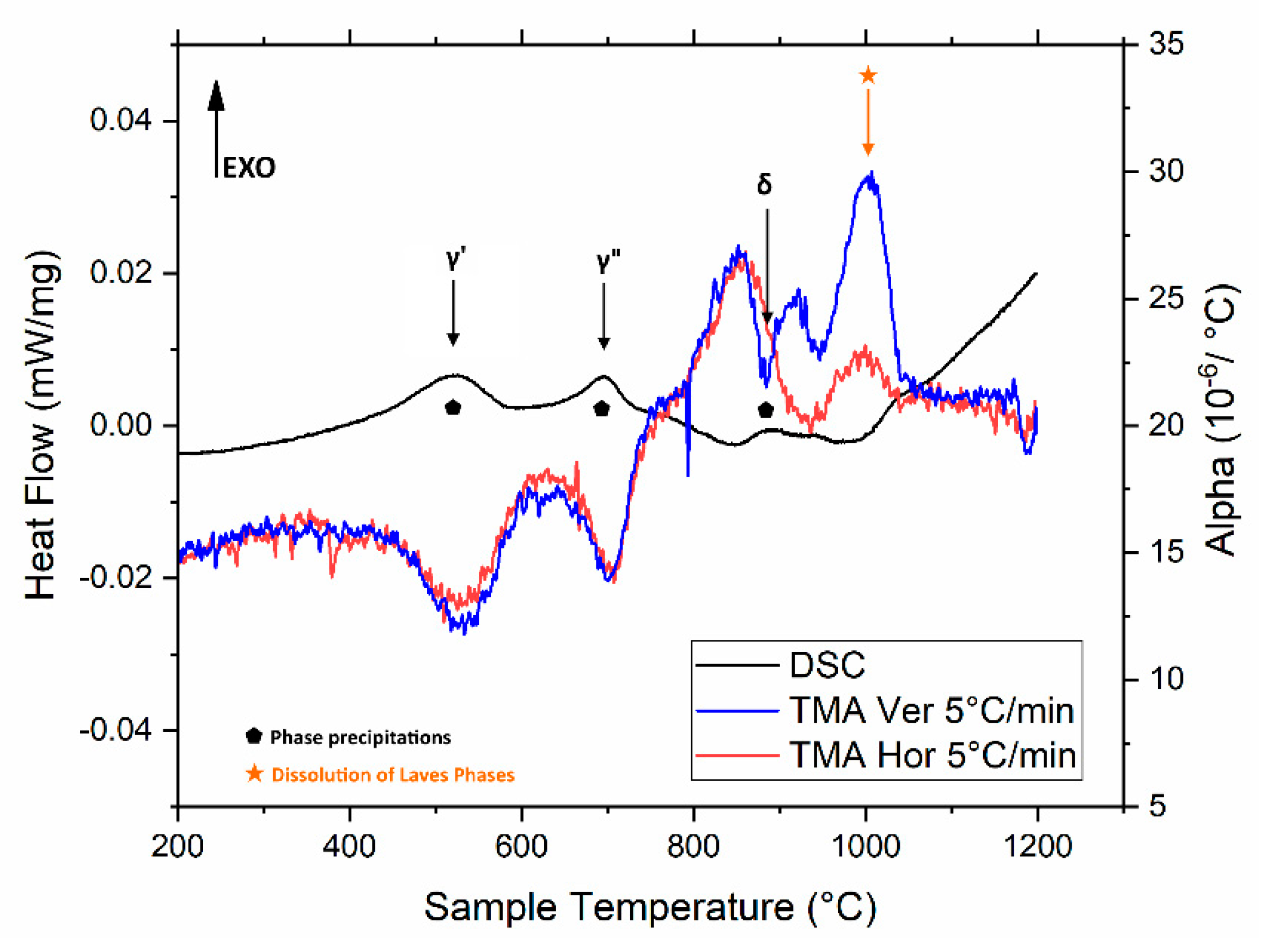
As can be seen, three exothermic and an endothermic peaks can be observed in the heating ramp and are indicated with black arrows. Peaks are related to the precipitation of γ′, γ″, and δ at 565, 755, and 880 °C, respectively. These temperatures were also mentioned in a previous paper [13]. On the other hand, the endothermic peak found in the range 980–1070 °C indicates the dissolution of all the pre-existing metastable phases. The results of the TMA analysis are reported together with the collected DSC curves in Figure 2 using the same heating ramp. Note that each exothermal peak is associated with a contraction of the material, i.e., a downward inversion of the CTE. Conversely, the endothermal peaks are associated with expansions, i.e., upward inversions of the measured CTE. In the plot, samples obtained along Z (building direction) are referred to as Ver, while XY ones to as Hor.
The detected exothermal peaks correspond to the precipitations of new phases. This phenomenon depleted the matrix of Nb from the solid solution, and therefore, the lattice distortion of γ was reduced. This process led to a material contraction, as evidenced in the TMA signals. Conversely, the endothermal phenomena observed with the DSC analysis are related to the dissolution of the second phases. The resulting solid-state diffusion enriches the matrix in solute, causing the lattice expansion observed during the TMA.
The combined use of different thermal analyses reveals the following solid-state events in the as-built IN718, which can be interpreted based on the alloy CCT curves [33]: the precipitation of γ′ between 450 and 630 °C; the precipitation of γ″ between 660 and 800 °C; and the dissolution of metastable second phases (Laves) between 950 and 1050 °C. A similar interpretation was also reported by Niang et al. [32] only for the exothermal peaks.
The TMA signals recorded on the vertical and horizontal samples (Figure 2) match everywhere except in the 850–950 °C temperature range (see Figure 2). This difference indicates that the lattice distortion caused by the dissolution of Laves phases and the formation of δ precipitates in this temperature range is not isotropic but occurs mainly along the building direction of the samples. This behavior may be connected to the elongated shape of the columnar grains inherited from the building process. This preferential orientation of the grain may act as a preferential nucleation site for the δ phase, which tends to grow in a single direction and may share numerous lattice positions with the austenitic matrix. Similar behavior was also observed in hot rolled austenitic stainless steels, where carbides preferentially develop at elongated grain boundaries of the rolled material, as discussed by Lakshmi et al. in a work about AISI 304 [34]. Furthermore, even though a TMA analysis was not performed, Fayed et al. noticed a higher amount of the δ phase along the building direction of LPBF IN718, in good agreement with the findings mentioned above [35].
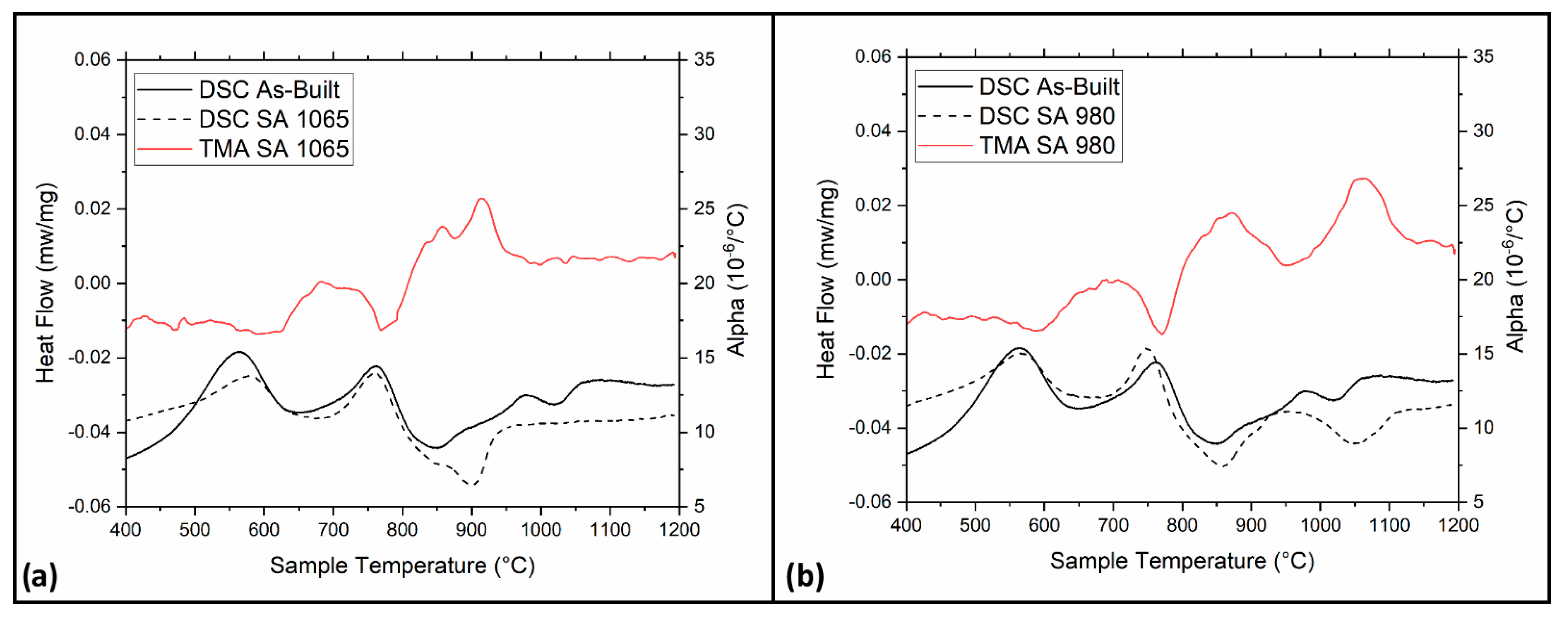
The thermal analyses were also repeated with samples that underwent an annealing process. Figure 3 shows the results of the DSC and TMA performed on the solutioned samples at 980 and 1065 °C for 2 h. These two temperatures were chosen based on a previous work by the same authors [13]. Again, the detected peaks are similar to those of the as-built material, with the peak that refers to the dissolution of pre-existing metastable phases being the only exception.
After solution annealing at 980 °C, this peak is more evident because of the higher presence of δ, which formed during the heat treatment [30]. Conversely, this peak is absent after solution annealing at 1065 °C. This fact was due to the dissolution of all the pre-existing precipitates during the annealing.
The DSC and TMA analyses reported in Figure 2 and Figure 3 are used to tailor the final heat treatment of the alloy because they provide a complete picture of the phase transformations brought by the thermal exposure

3.2. Effects of the Heat Treatment on the Microstructure

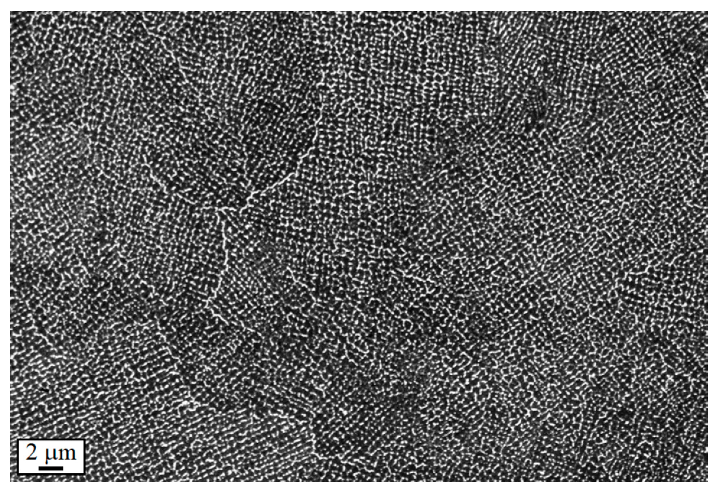
Figure 4 shows the microstructure of LPBF IN718 in the as-built state at low magnification using FESEM. Knowing the starting microstructure of the material makes it easier to understand the principal modification caused by each heat treatment phase. Despite the low magnifications, the columnar dendrites are easily visible, and many precipitates can be observed at their boundaries. This feature is compatible with a strong Nb segregation. It should be noted that the as-built microstructure was discussed in depth in a former work [13].

3.2.1. Direct Aging at 650 and 720 °C for 8 h

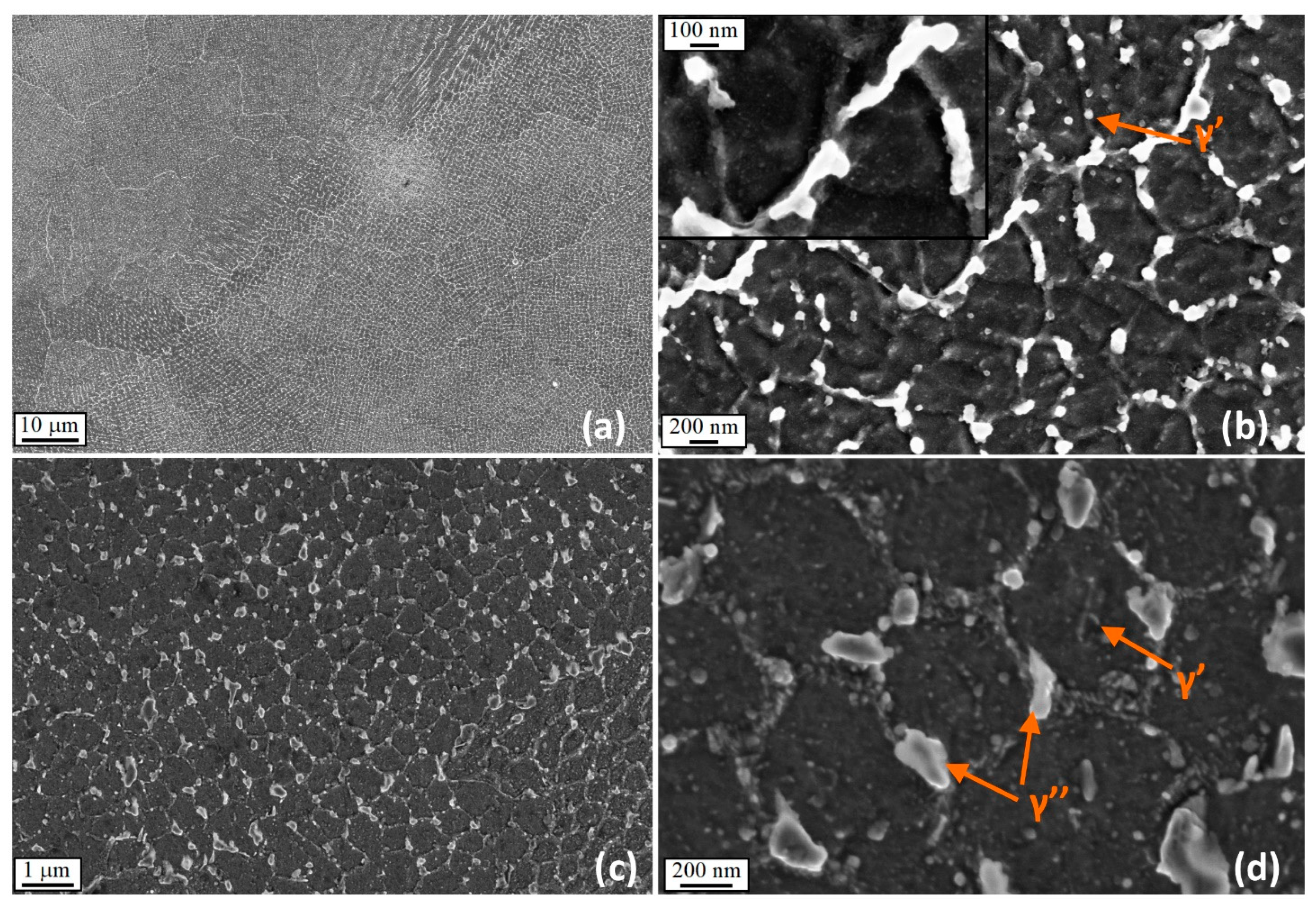
Figure 5 shows the FESEM micrographs of the samples aged for 8 h at 650 °C and 720 °C without a preliminary solution annealing. The direct aged samples are characterized by fine intergranular dendrites with a size of roughly 1 µm. At their boundaries, a large amount of segregation can be observed. These features were already present in the as-built state [13], as shown in Figure 4 and Figure 5a, and they cannot be modified due to the low temperatures of the aging treatments. However, direct aging causes the precipitation of very small γ′ particles uniformly dispersed, as shown in Figure 5b. In addition, γ″ precipitates were evidenced, mainly located along the interdendritic boundaries (Figure 5b). The most significant part of the γ″ phase formed at the dendritic boundaries because of the higher concentration of niobium in these regions [13]. Many small discoidal precipitates can be observed in samples aged at 720 °C, whereas some fine rounded particles were visible in the samples aged at 650 °C. Based on the thermal analysis, one can conclude that the aging at 720 °C leads to large precipitations of the γ″ phase. Conversely, the aging at 650 °C leads only to precipitation of very fine γ′ particles, which may cause a lower strengthening of the alloy.
Notably, together with rounded precipitates, a film of second phases was found in these samples at the interdendritic boundaries. This last evidence should be stressed because particles with this specific aspect ratio are generally detrimental for ductility since they act as a local stress raiser.

3.2.2. Solution Annealing

To better understand the choices made in the following sections, it is crucial to understand which metallurgical alterations are expected after solution annealing. These modifications were extensively debated in [30], and the main points are discussed in the next subsection. LPBF IN718 requires a post-solution treatment to reduce the segregation of heavier elements (particularly Nb) and to dissolve the interdendritic precipitates. Despite this, the annealing treatment can be performed only in a defined temperature range. When temperatures are excessively high, a strong grain coarsening leads to a sudden reduction of mechanical properties.
On the other hand, if the temperature is too low, an insufficient quantity of segregated particles will be dissolved, which limits the corrosion resistance of the alloy. According to this work, the best temperature range for enhancing the oxidation resistance falls between 980 and 1065 °C. The previous paper did not investigate the resulting microstructures or the mechanical properties after the annealing treatment, which are examined here instead.
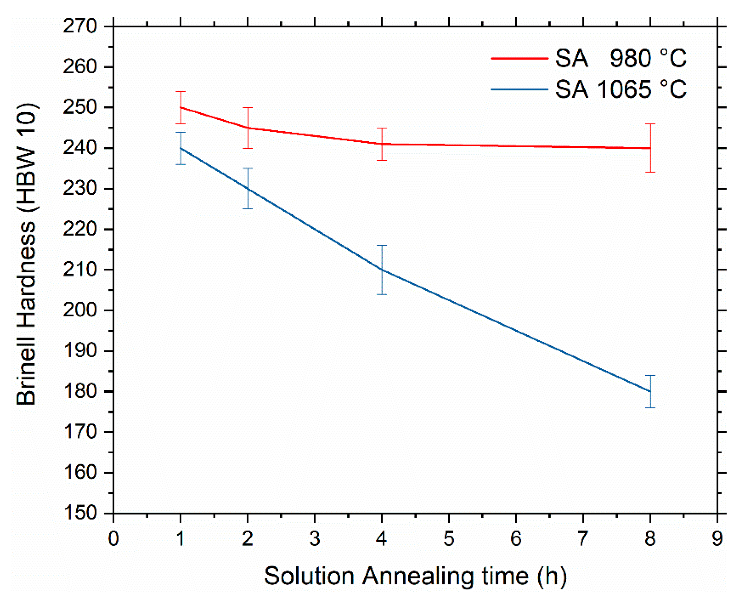
Figure 6 shows the effect of the annealing treatment on the material hardness. When the treatment was performed at a low temperature, only negligible effects were obtained. The temperature was too low to dissolve any particles, and the hardness decreased only due to a reduction of the residual stresses. According to the work cited above, a time of 2 h was considered the best compromise to perform the subsequent heat treatment steps.
As observed, solution annealing led to a more consistent hardness decrease when performed at 1065 °C. Furthermore, this effect becomes highly evident when solution annealing lasts excessively (see Figure 6). This effect is mainly connected to excessive grain growth in the material. Therefore, the duration of the annealing step must be carefully chosen. Based on these considerations and previous experiences [30], the solution annealing was interrupted after 2 h to avoid excessive softening of the material.

3.2.3. Solution Annealing at 980 °C and Aging at 650 or 720 °C

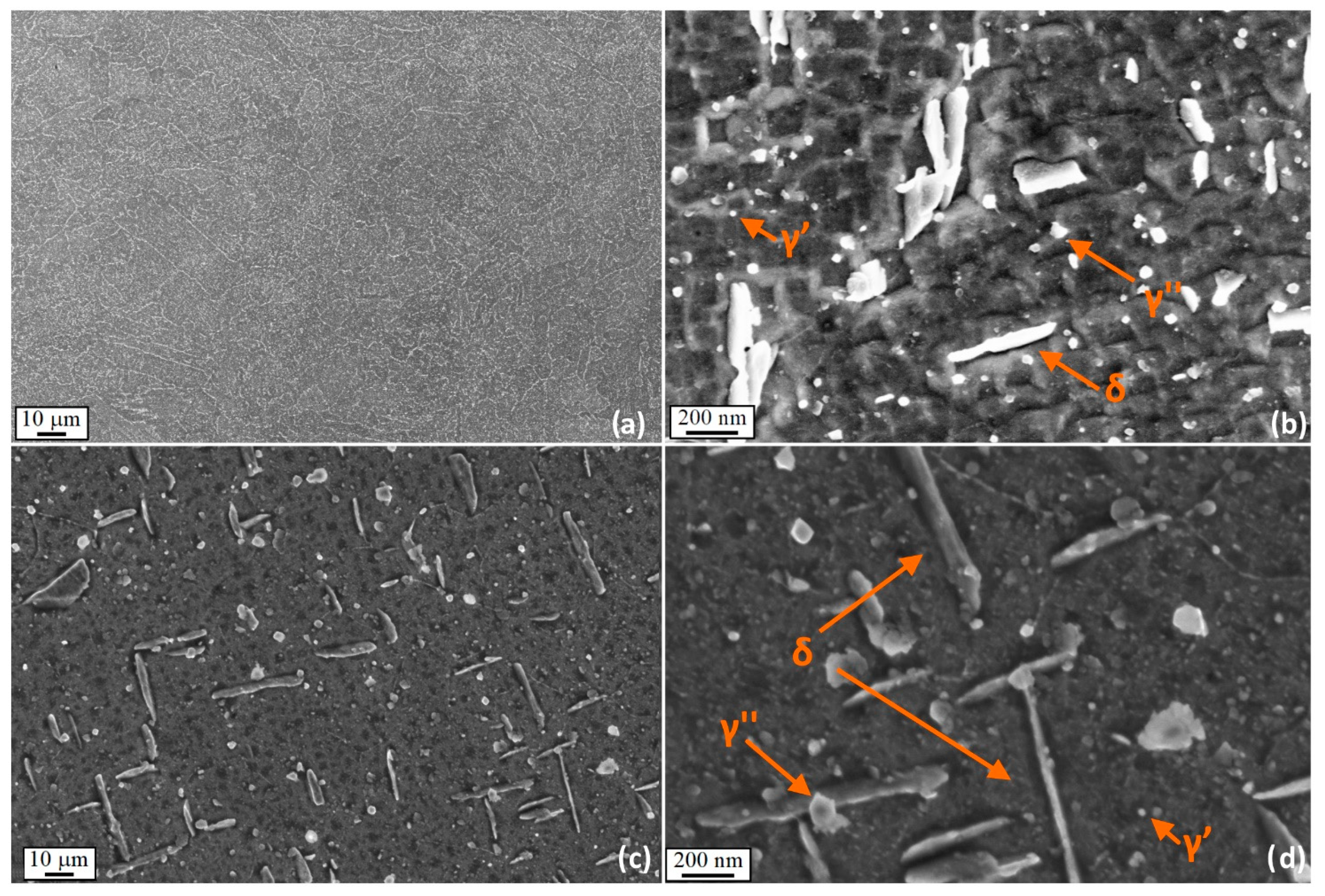
Figure 7a,b shows the microstructure after solution annealing at 980 °C and aging at 650 °C at different magnifications. On the other hand, Figure 7c,d shows the material solutioned at the same temperature but aged at 720 °C.
These conditions are characterized by relatively coarse plates of δ phase with a size ranging between 500 and 1000 nm in length. The 980 °C solution annealing stabilized these needle-like precipitates. In fact, their dissolution may only happen between 1005 °C and 1015 °C, as also mentioned in [27].
The presence of δ can affect the subsequent formation of the γ″ phase during the aging step because it reduces the availability of Nb in solid solution. Therefore, γ″ precipitation is not uniform. This experimental observation indicates that the annealing temperature is not high enough to dissolve the dendritic structures and to homogenize the material.
Nevertheless, the presence of brittle and elongated particles could be problematic for ductility and fatigue resistance. Thus, this microstructure cannot be considered ideal, and higher annealing temperatures should be investigated.

3.2.4. Solution Annealing at 1065 °C and Aging at 650 or 720 °C

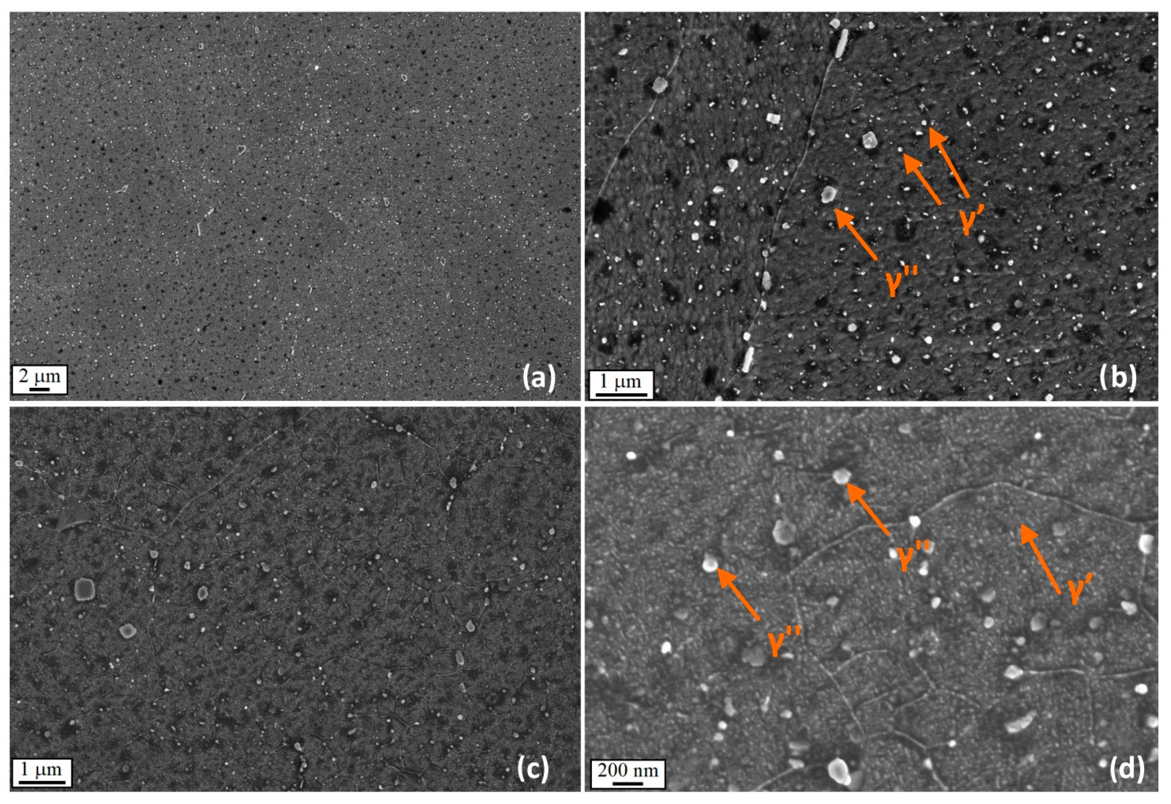
After solution annealing at 1065 °C, the grain boundaries became decorated with many intergranular precipitates. In contrast with the previous case, δ did not form during the heat treatment because it wholly dissolved during the annealing process see Figure 8. This fact also explains why the dendritic subgranular structure was no longer visible after the heat treatment at 1065 °C. Furthermore, some very fine rounded particles were visible in the samples aged at 650 °C, whereas many small discoidal precipitates can be observed in samples aged at 720 °C. Therefore, based on the thermal analysis, one can conclude that the aging at 720 °C leads to a relevant increase of the hardness because of the large precipitations of the γ″ phase. Conversely, the aging at 650 °C leads to the precipitation of few and very fine γ′ particles, and consequently a lower strengthening should be expected.
After this first optimization part, the main conclusion is that solution annealing is fundamental for gaining a sufficient degree of homogeneous precipitation. Conversely, in the direct aged samples, the precipitation of strengthening phases is highly irregular. Moreover, it occurs mainly at the interdendritic boundaries, where the local levels of Nb, Ti, and Al are higher due to microsegregation.

3.3. Hardness after Direct Aging and Comparison with Solutioned and Aged Samples

Figure 9 presents a comprehensive comparison of all the possible heat treatments analyzed up to now, considering that the hardness of the material in the as-built state was 264 ± 6 HBW 10. From this plot, it is possible to state some critical points: First of all, the direct aging at 720 °C is the treatment that provides the highest hardness. In comparison, the direct aging at 650 °C leads only to a subtle enhancement of the mechanical properties. Furthermore, the solution annealing at 980 °C leads only to a slight increase of hardness and is independent from the chosen aging temperature. Similar results were also obtained with solution annealing at 1065 °C but only when the lower aging temperature was picked.
Although solution annealing at 1065 °C by itself lowered the hardness considerably, this initial limitation was recovered entirely when the annealing was coupled with the aging at 720 °C. As shown in Figure 9 with a red triangle, the hardness level achieved is the second-highest value (irrespective of the aging time). Thus, even though the final hardness was slightly lower than the sample directly aged at 720 °C, the annealed and aged sample was preferred because of its more even microstructure. More specifically, this choice aims to dissolve the pre-existing eutectics precipitates, which allowed for a more homogeneous microstructure and a higher amount of free Nb for γ″ and γ′ formation in the last steps of the treatment.
It is noteworthy that according to the microstructural observations, the solution step leads to a more uniform distribution of the strengthening γ″ precipitates after aging. Finally, the solution treatment is also considered an appropriate choice for getting rid of the undissolved Laves phases.
The experimental observations performed led us to conclude that a preliminary solution annealing at 1065 °C followed by first aging at 720 °C is the most suitable heat treatment recipe to enhance both hardness and microstructural uniformity. For this reason, from now on, the remaining part of the heat treatment optimization is performed on samples annealed at 1065 °C. Experimental points in Figure 9 are linearly interpolated, always obtaining R2 values higher than 0.993, indicating an excellent fitting result.

3.4. Second Aging at 520 and 630 °C

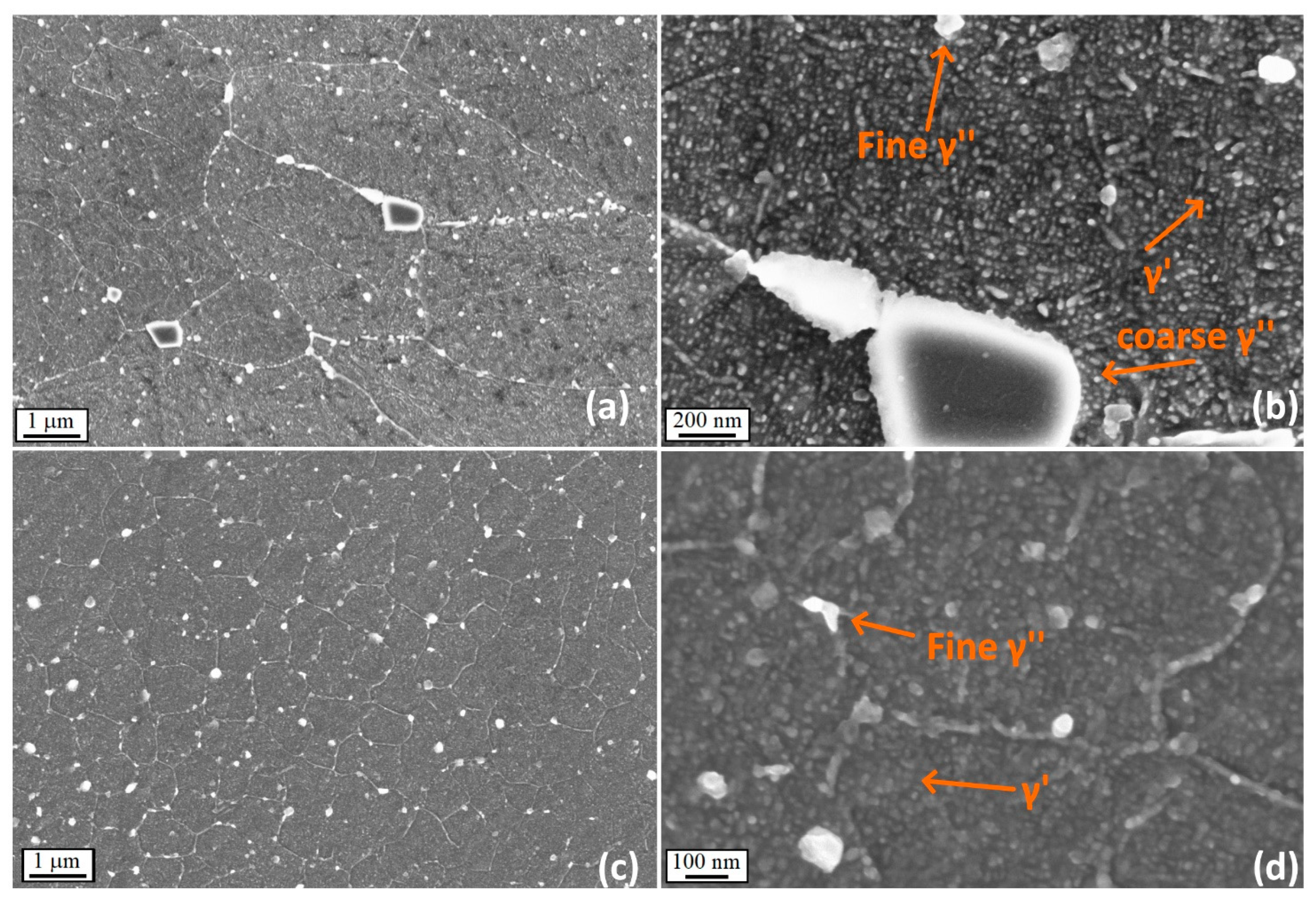
Figure 10 shows the microstructure of the samples after the second aging step. The treatment was performed at two different temperatures. During the second aging, the amount of interdendritic precipitates further increased. Based on the thermal analysis outcome, γ′ was expected to form at this temperature level. During the second aging, the new γ′ particles synergically played with the γ″ developed during the first aging, generating a further increase in hardness. The peak hardness value was achieved quickly because of the rapid precipitation kinetic of γ′.
According to the micrographs at high magnification shown above, the exposure at more elevated temperatures promoted stronger precipitation, leading to a more effective reinforcement of the material, as discussed later in this section.
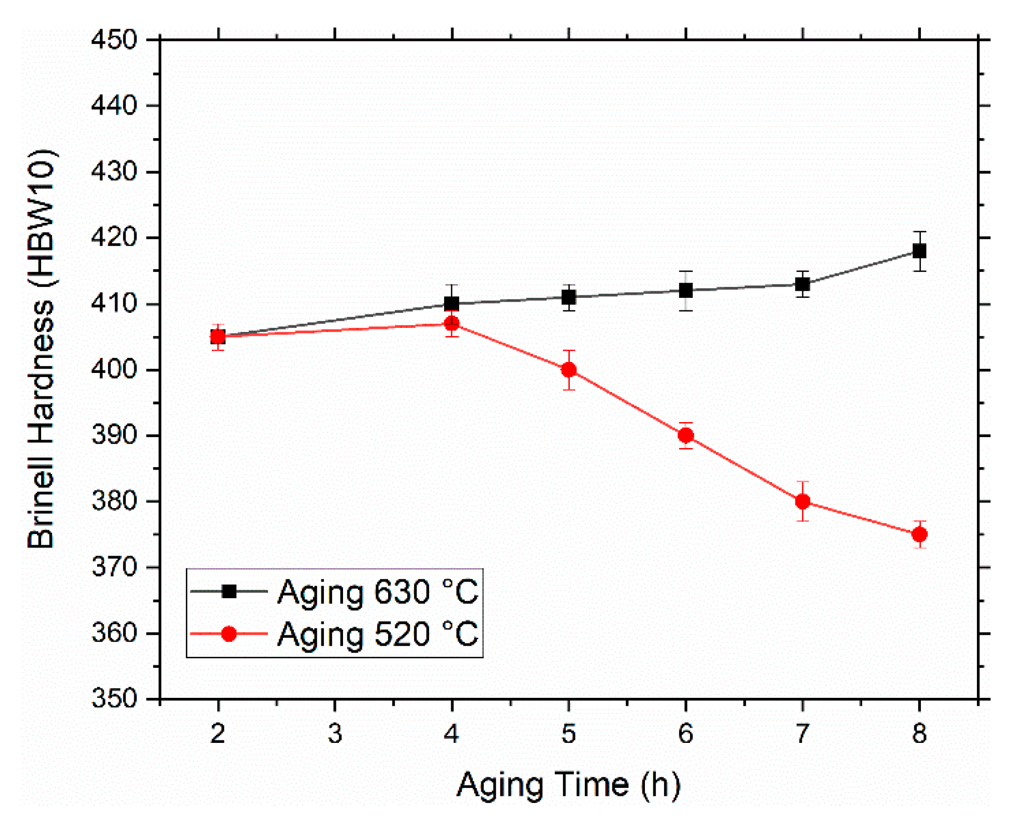
The Brinell hardness increased with the aging temperature, but the soaking time did not significantly contribute to it (Figure 11). For example, at 630 °C, the hardness reached a steady value after 4 h of treatment. Conversely, at 520 °C, a slight decrease of the hardness was observed after 8 h of aging. This effect could be due to the coarsening of the already formed precipitates without the contemporary formation of fresh reinforcing particles since the temperature is not high enough to promote the formation of further γ″.
The final hardness result achieved after the optimized heat treatment was 420 HBW 10. This value was compared with others in the literature for traditional wrought alloy [36] and the LPBF [37].
For example, Kashaev et al. used traditional IN718 for mechanical characterization, with a 12 μm grain size, and hardness was 210 HV (ca. 210 HBW 10 according to conversion charts). Such a difference can be related to the significantly finer microstructure obtained in this work, which was preserved throughout the entire heat treatment by adequately limiting the soaking time during the annealing step. Similar conclusions can also be stated when comparing the results presented by Nikolaos et al. [38], where mechanical properties of welded IN718 were investigated. The finer microstructure obtained after TIG welding allowed us to obtain a final hardness of 240 HV (ca. 228 HBW 10 according to conversion tables). In this case, the difference in hardness can be related to the different cooling rates during solidification, which is considerably slower in TIG applications. When hardness was compared with the material produced with the same laser bed techniques, it was found that the hardness gap was reduced. Jiang et al. [37] applied a traditional heat treatment to LPBF IN718, obtaining a final hardness of 404 HV (ca. 381 HBW 10 according to conversion charts). This result is a further confirmation that careful optimization of the process parameters and heat treatment is vital to enhance the final mechanical properties of a component.

4. Conclusions

The DSC and TMA analyses provided a helpful starting point for studying the microstructural evolution of Inconel 718 after production through the LPBF process.
The samples solutioned at 980 °C showed plate-like δ precipitates. It was noticed that their volume fraction increases with the time of the solution treatment. The presence of the δ phase after solutioning at 980 °C was also confirmed by the DSC and TMA analyses.
The presence of δ affected the alloy’s hardness in two opposite ways: it provided a certain strengthening during the solutioning treatment at 980 °C, preventing an excessive softening, and it strongly reduced the effectiveness of aging treatments since only a tiny amount of γ″ forms. Thus, the solution treatment at 1065 °C for 2 h seems to be the best compromise between microstructural homogenization, the dissolution of the pre-existing second phases, and the possibility of avoiding grain coarsening.
The final hardness of the alloy was mainly controlled by the selection of the temperatures of the aging steps. The first aging temperature of 720 °C was found to be the best choice for the formation of strengthening γ″ particles. During the second aging step, further γ′ strengthening particles can be formed. The most significant increase of hardness was obtained with the second aging performed at 630 °C.

Author Contributions

Conceptualization, E.B. and G.M.; methodology, E.B. and G.M.; validation, E.B., G.M., and A.A.; formal analysis, E.B.; investigation, G.M.; data curation, E.B.; writing—original draft preparation, E.B.; writing—review and editing, A.A. and G.M.; supervision, E.B., G.M., and A.A. All authors have read and agreed to the published version of the manuscript.

Funding

This research received no external funding.

Data Availability Statement

All relevant data supporting this research work are presented within the paper.

Acknowledgments

The authors thanks Michele Calandri for his valuable work during the initial conceptualization of the paper.

Conflicts of Interest

The authors declare no conflict of interest.

References

  1. Yap, C.Y.; Chua, C.K.; Dong, Z.L.; Liu, Z.H.; Zhang, D.Q.; Loh, L.E.; Sing, S.L. Review of selective laser melting: Materials and applications. Appl. Phys. Rev. 2015, 2, 041101. [Google Scholar] [CrossRef]
  2. King, W.E.; Anderson, A.T.; Ferencz, R.M.; Hodge, N.E.; Kamath, C.; Khairallah, S.A.; Rubenchik, A.M. Laser powder bed fusion additive manufacturing of metals; physics, computational, and materials challenges. Appl. Phys. Rev. 2015, 2, 041304. [Google Scholar] [CrossRef]
  3. Ngo, T.D.; Kashani, A.; Imbalzano, G.; Nguyen, K.T.Q.; Hui, D. Additive manufacturing (3D printing): A review of materials, methods, applications and challenges. Compos. Part B Eng. 2018, 143, 172–196. [Google Scholar] [CrossRef]
  4. Herzog, D.; Seyda, V.; Wycisk, E.; Emmelmann, C. Additive manufacturing of metals. Acta Mater. 2016, 117, 371–392. [Google Scholar] [CrossRef]
  5. Sames, W.J.; List, F.A.; Pannala, S.; Dehoff, R.R.; Babu, S.S. The metallurgy and processing science of metal additive manufacturing. Int. Mater. Rev. 2016, 61, 315–360. [Google Scholar] [CrossRef]
  6. Frazier, W.E. Metal additive manufacturing: A review. J. Mater. Eng. Perform. 2014, 23, 1917–1928. [Google Scholar] [CrossRef]
  7. Gu, D.D.; Meiners, W.; Wissenbach, K.; Poprawe, R. Laser additive manufacturing of metallic components: Materials, processes and mechanisms. Int. Mater. Rev. 2012, 57, 133–164. [Google Scholar] [CrossRef]
  8. Zhang, D.; Feng, Z.; Wang, C.; Wang, W.; Liu, Z.; Niu, W. Comparison of microstructures and mechanical properties of Inconel 718 alloy processed by selective laser melting and casting. Mater. Sci. Eng. A 2018, 724, 357–367. [Google Scholar] [CrossRef]
  9. Chlebus, E.; Gruber, K.; Kuźnicka, B.; Kurzac, J.; Kurzynowski, T. Effect of heat treatment on the microstructure and mechanical properties of Inconel 718 processed by selective laser melting. Mater. Sci. Eng. A 2015, 639, 647–655. [Google Scholar] [CrossRef]
  10. Zhang, D.; Niu, W.; Cao, X.; Liu, Z. Effect of standard heat treatment on the microstructure and mechanical properties of selective laser melting manufactured Inconel 718 superalloy. Mater. Sci. Eng. A 2015, 644, 32–40. [Google Scholar] [CrossRef]
  11. Popovich, V.A.; Borisov, E.V.; Popovich, A.A.; Sufiiarov, V.S.; Masaylo, D.V.; Alzina, L. Impact of heat treatment on mechanical behaviour of Inconel 718 processed with tailored microstructure by selective laser melting. Mater. Des. 2017, 131, 12–22. [Google Scholar] [CrossRef]
  12. Barros, R.; Silva, F.J.G.; Gouveia, R.M.; Saboori, A.; Marchese, G.; Biamino, S.; Salmi, A.; Atzeni, E. Laser Powder Bed Fusion of Inconel 718: Residual Stress Analysis Before and After Heat Treatment. Metals 2019, 9, 1290. [Google Scholar] [CrossRef] [Green Version]
  13. Calandri, M.; Yin, S.; Aldwell, B.; Calignano, F.; Lupoi, R.; Ugues, D. Texture and microstructural features at different length scales in Inconel 718 produced by selective laser melting. Materials 2019, 12, 1293. [Google Scholar] [CrossRef] [Green Version]
  14. Patel, A.D.; Murty, Y.V. Effect of cooling rate on microstructural development in alloy 718. Superalloys 2001, 718, 625–706. [Google Scholar]
  15. Knorovsky, G.A.; Cieslak, M.J.; Headley, T.J.; Romig, A.D.; Hammetter, W.F. INCONEL 718: A solidification diagram. Metall. Trans. A 1989, 20, 2149–2158. [Google Scholar] [CrossRef]
  16. Zaharia, S.M.; Chicoș, L.A.; Lancea, C.; Pop, M.A. Effects of homogenization heat treatment on mechanical properties of inconel 718 sandwich structures manufactured by selective laser melting. Metals 2020, 10, 645. [Google Scholar] [CrossRef]
  17. Carter, L.N.; Wang, X.; Read, N.; Khan, R.; Aristizabal, M.; Essa, K.; Attallah, M.M. Process optimisation of selective laser melting using energy density model for nickel based superalloys. Mater. Sci. Technol. 2016, 0836, 1–5. [Google Scholar] [CrossRef]
  18. Wang, Z.; Guan, K.; Gao, M.; Li, X.; Chen, X.; Zeng, X. The microstructure and mechanical properties of deposited-IN718 by selective laser melting. J. Alloys Compd. 2012, 513, 518–523. [Google Scholar] [CrossRef]
  19. Marchese, G.; Bassini, E.; Calandri, M.; Ambrosio, E.P.; Calignano, F.; Lorusso, M.; Manfredi, D.; Pavese, M.; Biamino, S.; Fino, P. Microstructural investigation of as-fabricated and heat-treated Inconel 625 and Inconel 718 fabricated by direct metal laser sintering: Contribution of Politecnico di Torino and Istituto Italiano di Tecnologia (IIT) di Torino. Met. Powder Rep. 2016, 71, 273–278. [Google Scholar] [CrossRef]
  20. Zhou, L.; Mehta, A.; McWilliams, B.; Cho, K.; Sohn, Y. Microstructure, precipitates and mechanical properties of powder bed fused inconel 718 before and after heat treatment. J. Mater. Sci. Technol. 2019, 35, 1153–1164. [Google Scholar] [CrossRef]
  21. Deng, D.; Peng, R.L.; Brodin, H.; Moverare, J. Microstructure and mechanical properties of Inconel 718 produced by selective laser melting: Sample orientation dependence and effects of post heat treatments. Mater. Sci. Eng. A 2018, 713, 294–306. [Google Scholar] [CrossRef]
  22. Li, J.; Zhao, Z.; Bai, P.; Qu, H.; Liu, B.; Li, L.; Wu, L.; Guan, R.; Liu, H.; Guo, Z. Microstructural evolution and mechanical properties of IN718 alloy fabricated by selective laser melting following different heat treatments. J. Alloys Compd. 2019, 772, 861–870. [Google Scholar] [CrossRef]
  23. Li, X.; Shi, J.J.; Cao, G.H.; Russell, A.M.; Zhou, Z.J.; Li, C.P.; Chen, G.F. Improved plasticity of Inconel 718 superalloy fabricated by selective laser melting through a novel heat treatment process. Mater. Des. 2019, 180. [Google Scholar] [CrossRef]
  24. Azadian, S.; Wei, L.Y.; Warren, R. Delta phase precipitation in inconel 718. Mater. Charact. 2004, 53, 7–16. [Google Scholar] [CrossRef]
  25. Jouiad, M.; Marin, E.; Devarapalli, R.S.; Cormier, J.; Ravaux, F.; Le Gall, C.; Franchet, J.M. Microstructure and mechanical properties evolutions of alloy 718 during isothermal and thermal cycling over-aging. Mater. Des. 2016, 102, 284–296. [Google Scholar] [CrossRef]
  26. Cao, G.H.; Sun, T.Y.; Wang, C.H.; Li, X.; Liu, M.; Zhang, Z.X.; Hu, P.F.; Russell, A.M.; Schneider, R.; Gerthsen, D.; et al. Investigations of γ′, γ″ and δ precipitates in heat-treated Inconel 718 alloy fabricated by selective laser melting. Mater. Charact. 2018, 136, 398–406. [Google Scholar] [CrossRef] [Green Version]
  27. Páramo Kañetas, P.J.; Reyes Osorio, L.A.; Guerrero Mata, M.P.; De La Garza, M.; Páramo López, V. Influence of the Delta Phase in the Microstructure of the Inconel 718 subjected to “Delta-processing” Heat Treatment and Hot Deformed. Procedia Mater. Sci. 2015, 8, 1160–1165. [Google Scholar] [CrossRef] [Green Version]
  28. Zhong, C.; Gasser, A.; Kittel, J.; Wissenbach, K.; Poprawe, R. Improvement of material performance of Inconel 718 formed by high deposition-rate laser metal deposition. Mater. Des. 2016, 98, 128–134. [Google Scholar] [CrossRef]
  29. Tucho, W.M.; Cuvillier, P.; Sjolyst-Kverneland, A.; Hansen, V. Microstructure and hardness studies of Inconel 718 manufactured by selective laser melting before and after solution heat treatment. Mater. Sci. Eng. A 2017, 689, 220–232. [Google Scholar] [CrossRef]
  30. Calandri, M.; Manfredi, D.; Calignano, F.; Ambrosio, E.P.; Biamino, S.; Lupoi, R.; Ugues, D. Solution Treatment Study of Inconel 718 Produced by SLM Additive Technique in View of the Oxidation Resistance. Adv. Eng. Mater. 2018, 20, 1–16. [Google Scholar] [CrossRef]
  31. Ni, M.; Chen, C.; Wang, X.; Wang, P.; Li, R.; Zhang, X. Materials Science & Engineering A Anisotropic tensile behavior of in situ precipitation strengthened Inconel 718 fabricated by additive manufacturing. Mater. Sci. Eng. A 2017, 701, 344–351. [Google Scholar] [CrossRef]
  32. Niang, A.; Viguier, B.; Lacaze, J. Some features of anisothermal solid-state transformations in alloy 718. Mater. Charact. 2010, 61, 525–534. [Google Scholar] [CrossRef] [Green Version]
  33. Garcia, C.I.; Lis, A.K.; Loria, E.A.; DeArdo, A.J. Thermomechanical Processing and Continuous Cooling Transformation Bebavior of IN-718. In Proceedings of the Superalloys; Antolovich, S.D., Stusrud, R.W., MacKay, R.A., Anton, D.L., Khan, T., Kissinger, R.D., Klarstrom, D.L., Eds.; The Minerals, Metals & Materials Society: Pittsburgh, PA, USA, 1992; pp. 527–536. [Google Scholar] [CrossRef]
  34. Lakshmi, A.A.; Rao, C.S.; Buddi, T. Chapter five—Fractography analysis and constitutive modeling for dynamic plasticity of austenite stainless steel (ASS 304) at hot-working temperatures. In Woodhead Publishing Reviews: Mechanical Engineering Series, Modern Manufacturing Processes; Elsevier: Amsterdam, The Netherlands, 2020; ISBN 9780128194966. [Google Scholar]
  35. Fayed, E.M.; Saadati, M.; Shahriari, D.; Brailovski, V. Effect of homogenization and solution treatments time on the elevated—Temperature mechanical behavior of Inconel 718 fabricated by laser powder bed fusion. Sci. Rep. 2021, 11, 1–17. [Google Scholar] [CrossRef] [PubMed]
  36. Kashaev, N.; Horstmann, M.; Ventzke, V.; Riekehr, S.; Huber, N. Comparative study of mechanical properties using standard and micro-specimens of base materials Inconel 625, Inconel 718 and Ti-6Al-4V. J. Mater. Res. Technol. 2013, 2, 43–47. [Google Scholar] [CrossRef]
  37. Jiang, R.; Mostafaei, A.; Pauza, J.; Kantzos, C.; Rollett, A.D. Materials Science & Engineering A Varied heat treatments and properties of laser powder bed printed Inconel. Mater. Sci. Eng. A 2019, 755, 170–180. [Google Scholar] [CrossRef]
  38. Alexopoulos, N.D.; Argyriou, N.; Stergiou, V.; Kourkoulis, S.K. Fatigue behavior of Inconel 718 TIG welds. J. Mater. Eng. Perform. 2014, 23, 2973–2983. [Google Scholar] [CrossRef]
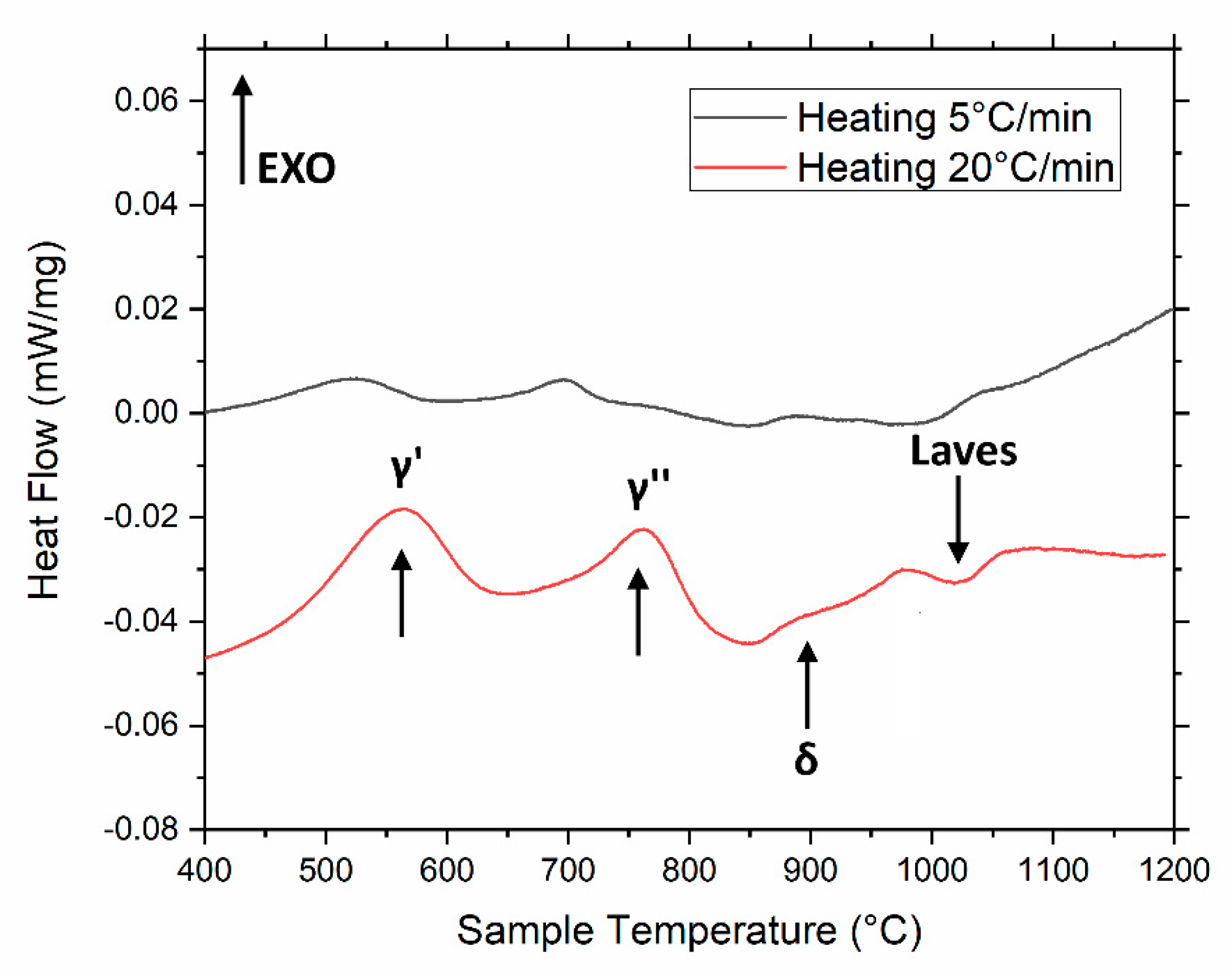
Figure 1. Differential scanning calorimetry (DSC) of as-built Inconel 718 at different heating rates. The arrows indicate the peaks detected, as also found in [13,32].
Metals 11 00921 g001
Figure 2. Thermomechanical analysis (TMA) of as-built IN718. Heating rate is 5 °C/min. The relevant DSC curve is presented as well.
Metals 11 00921 g002
Figure 3. DSC and TMA of IN718 after solution annealing at 1065 °C (a) and 980 °C (b); solid and dashed lines refer to DSC and TMA, respectively.
Metals 11 00921 g003
Figure 4. Microstructure of IN718 in the as-built state observed with secondary electron detector.
Metals 11 00921 g004
Figure 5. IN718 observed under a secondary electrons (SE) detector after direct aging at 650 °C for 8 h (a,b) and after direct aging at 720 °C for 8 h (c,d).
Metals 11 00921 g005
Figure 6. Brinell hardness as a function of solution annealing time at two different temperatures.
Metals 11 00921 g006
Figure 7. Microstructure after solution annealing at 980 °C for 2 h and subsequent aging at 650 °C for 8 h at different magnification low (a) and high (b). Microstructure after solution annealing at 980 °C for 2 h and subsequent aging at 720 °C for 8 h at different magnification low (c) and high (d).
Metals 11 00921 g007
Figure 8. Microstructure after solution annealing at 1065 °C for 2 h and subsequent aging at 650 °C for 8 h at low (a) and high (b) magnification. Microstructure after solution annealing at 1065 °C for 2 h and subsequent aging at 720 °C for 8 h at low (c) and high (d) magnification.
Metals 11 00921 g008
Figure 9. Hardness levels as an effect of all the heat treatment performed; dashed lines are the linear interpolations of the experimental points. All the linear regressions gave an R2 value higher than 0.993.
Metals 11 00921 g009
Figure 10. Microstructure after solution annealing at 1065 °C followed by the first aging at 720 °C and second aging at 520 °C for 8 h at different magnification: low (a) and high (b). A second aging at 630 °C for 8 h at different magnification: low (c) and high (d).
Metals 11 00921 g010
Figure 11. Hardness assessment after second aging at two different temperatures.
Metals 11 00921 g011
Table 1. Chemical composition in weight percent of the employed gas atomized powder.
NiCrNbMoTiAlCoCuCSi + MnP + SBFe
52.5195.1253.050.90.5<1<0.3<0.08<0.35<0.015<0.006Bal.
Table 2. List of the heat treatments performed (X = 1, 2, 4, 8 h; Y = 4, 8 h; Z = 1, 2, 4, 8 h).
Sample AcronymSolution AnnealingAgingSecond Aging
DA650-650 °C for Y h-
DA720-720 °C for Y h-
SA980 (X) A650 (Y)980 °C for X h650 °C for Y h-
SA980 (X) A720 (Y)980 °C for X h720 °C for Y h-
SA1065 (X) A650 (Y)1065 °C for X h650 °C for Y h-
SA1065 (X) A720 (Y)1065 °C for X h720 °C for Y h-
SA1065 (X) A720 (Y) A520 (Z)1065 °C for X h720 °C for Y h520 °C for Z h
SA1065 (X) A720 (Y) A630 (Z)1065 °C for X h720 °C for Y h630 °C for Z h
Publisher’s Note: MDPI stays neutral with regard to jurisdictional claims in published maps and institutional affiliations.