Article

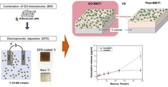
Electrophoretic Deposition of a Hybrid Graphene Oxide/Biomolecule Coating Facilitating Controllable Drug Loading and Release

Department of Nano-Biomedical Science & BK21 PLUS NBM Global Research Center for Regenerative Medicine, Dankook University, Cheonan 31116, Korea
*
Author to whom correspondence should be addressed.
Metals 2021, 11(6), 899; https://doi.org/10.3390/met11060899
Submission received: 16 April 2021 / Revised: 27 May 2021 / Accepted: 28 May 2021 / Published: 31 May 2021
(This article belongs to the Special Issue Titanium and Its Alloys for Biomedical Applications)

Abstract

:
Two-dimensional (2D) graphene oxide (GO) exhibits a high drug loading capacity per unit mass due to its unique structure and hydrophilicity and has been widely researched for drug-delivery systems. Here, we modified the surfaces of metal implants; we applied GO-based coatings that controlled drug loading and release. We used electrophoretic deposition (EPD) to apply the coatings at room temperature. The EPD coatings were analyzed in terms of their components, physical properties such as hardness and hydrophilicity, and in vitro cell tests of their biological properties. Uniform GO-EPD coatings improved surface hydrophilicity and hardness and greatly improved the bone differentiation properties of the metal substrate. Drug loading and release increased greatly compared to when the drug was adsorbed to only the surface of a coating. GO facilitated deposition of a drug-containing coating via EPD, and the surface modification, and drug loading and release, were controlled by the thickness of the coating.

Graphical Abstract

1. Introduction

Metals are widely used to replace damaged bones, especially load-bearing bones [1]. Any metal is a bioinert material, the use of which raises concerns about (poor) biocompatibility, inappropriate mechanical properties, and inflammatory/immune reactions caused by metal ion dissolution [2]. Surface modifications of dental or orthopedic metal-based implants enhance biocompatibility and functionality [3,4]. Surface treatments may be physical, chemical, or biological in nature. Physical methods may alter the surface morphology to induce attachment to regenerated bone, or oxidize the implant surfaces to increase hydrophilicity and reduce corrosion caused by micro-arc oxidation and anodizing [5]. Chemical methods alter the surface of implants without significantly affecting their bulk properties, yielding hard, wear-resistant hydrophilic surfaces. The various techniques include chemical vapor deposition (CVD), plasma vapor deposition (PVD), ion-beam deposition (IBAD), grafting techniques, and the use of self-assembling monolayers (SAMs) [6,7,8,9]. Biological methods effectively improve the biological properties of bioinert metal implants [10].
Synthetic biomimetic strategies enhancing the functionality of metal-based implants have focused principally on the addition of biomolecules to implant surfaces. Growth factors and protein-mimetic peptides improve the interactions between the implant and the biological environment, with preservation of the bulk implant’s mechanical properties [11]. Reactive groups are required for biomolecular tethering. However, bioinert metal surfaces lack such groups. Surface active groups (e.g., –OH, –COOH, and –NH2) are essential for surface modification. Oxygen-terminal carbon-based materials facilitate strong physisorption of biomolecules to carbon-based materials [12].
Graphene oxide (GO) contains several reactive oxygen groups (e.g., C=O, COOH, OH, and C-O-C), suspends well in water, and interacts with biomolecules and drugs. The unique flake-type two-dimensional (2D) structure is associated with high drug loading per unit of GO mass; the GO surface area is high. GO exhibits good mechanical properties, good biocompatibility (especially in terms of osteoconductivity), and good antimicrobial activity. GO is an optimal coating for orthopedic implants [13,14]. There are many reports that carbon-based materials, such as graphene, combined with biomolecules (BM) are effective in regenerating bone tissue. Examples include complexes of carbon-based materials with BM such as BMP-2, FGFs, and Simvastatin [15,16,17]. In addition, these complexes have been produced in various forms, including film, coating, particles, scaffolds, and fibers, and the properties analyzed and widely applied in implants research for tissue regeneration [18,19,20,21]. Biomimetic surface modifications enhance implant function; however, biomolecules are vulnerable to high temperatures, strong acid/base conditions, and chemical solvents [22]. Therefore, many studies use natural biopolymers as a base material that can be processed in aqueous conditions to prevent the stability of biomolecules, or incorporate biomolecules after the fabricating process of base materials is completed [21,23]. In particular, the surface modifications of metal implants require the gentle condition for all processes including the preparation of BM-combined composites and deposition of them on the surface. The electrophoretic deposition (EPD) method can be used to form coatings from aqueous solutions at room temperature. EPD deposits colloidal particles in an aqueous electrolytic bath onto substrates. The coating time is short, and the coatings are uniform and continuous [24,25]. EPD has been used to produce graphene films, graphene-based reinforced composites, complex materials, interleaved porous structures, and nanoparticle-spaced graphene films [26]. To modify the surfaces of implants used for hard-tissue engineering, researchers have sought to reduce internal corrosion, increase hardness, and enhance biocompatibility by the addition of biopolymers; however, few studies have explored combinations of GO with therapeutic drugs. We are the first to use EPD to develop GO-biomolecule (GO-BM) hybrid coatings of controllable thickness; the coatings contain large amounts of drugs. If BMs are exposed on an implant surface, an additional layer is required to protect the BMs from loss or denaturation during transplantation. Our method reduces BM damage and allows control of drug loading and release. It is a technology applicable to drug-eluting stents or orthopedic implants development, which is expected to lead to enhanced therapeutic effects. In this study, GO-EPD coatings for biomedical applications were evaluated in terms of composition, physical properties, cellular interactions, and drug release [27,28,29,30].

2. Materials and Methods

2.1. Materials

Titanium plates (bare Ti of grade 2, Titanart, Incheon, Korea) served as EPD substrates. The plates were polished with 800- and 1200-grit silicon carbide paper and ultrasonically cleaned in acetone, ethanol (Duksan, Ansan, Korea), and distilled water (5 min for each bath). Single-layer GO was from Graphene Supermarket (Ronkonkoma, NY, USA). Ethanol (Duksan, Ansan, Korea) was 99.6% pure. Green fluorescence protein (GFP) and bone morphogenic protein-2 (BMP-2) were supplied by Genoss, Gyeonggi-do, Korea.

2.2. Electrophoretic GO Deposition

A GO suspension (500 µg/mL) was prepared in 80% (v/v) ethanol and sonicated for 15 min. Ti plates were submerged in the suspension at 1 cm from the cathode, and EPD proceeded at 10 mA for 1 min. The plates were then dried and stored in a desiccator. Prior to biological tests, the coated plates were sterilized with 70% (v/v) ethanol. EPD was also used to prepare drug-eluting coatings; the test BMs were GFP and BMP-2. Various amounts of the BMs (10, 25, 50, and 100 µg/mL) were added to GO suspensions or GO-coated Ti plates, magnetically stirred for 3 h, and EPD was performed or drug release was assessed.

2.3. Characterization

The surface morphology and coating thicknesses were studied via scanning electron microscopy (SEM; JSM-6510, JEOL Ltd., Tokyo, Japan). X-ray diffraction (XRD; Ulima Ⅳ, Rigaku, Tokyo, Japan) was used to define the phase compositions of Ti and GO-coated Ti. The test voltage was 40 kV and the current was 40 mV; Cu-Kα radiation was delivered (λ = 1.540598 Å) over a 2θ range of 5–70° with a step size of 1° and a count time of 1 min/step. A Raman spectroscopy (DXR2xi, Thermo Fisher, Waltham, MA, USA) was performed at 532 nm. Zeta potentials were measured using a Zetasizer (Nano-ZS, Malvern Instruments, Malvern, UK) with water as the dispersant. The electrophoretic mobilities of suspensions were converted to zeta potentials. An X-ray photoelectron spectroscopy (XPS; Axis Supra, Kratos, UK) was performed with the aid of focused, monochromatized Al Ka radiation (hν = 1486.6 eV). An atomic force microscope (AFM) (Bruker Dimension Edge, Middlesex County, MA, USA) was used to characterize surface microstructure and morphology. Coating hardness was measured using a Vickers indenter (HM-221, Mitutoyo, Kanagawa, Japan) at a load of 0.98 N. Contact angles (D7334-08 device, ASTM, Montgomery County, PA, USA) were used to measure the surface wettabilities of Ti and GO-coated Ti plates.

2.4. BM Loading and Release

BM (100 μg/mL) loading and release into/from GO before and after GO-EPD were evaluated by visualizing the GFP via confocal laser scanning spectroscopy (CLSM, Zeiss-LSM510, Carl Zeiss, Oberkochen, Germany). The extent of fluorescence reflected the BM level. BM loaded onto and then released from GO-BM/Ti coatings was measured by ELISA after immersing the complexes in phosphate-buffered saline (PBS) pH 7.4 at 37 °C for up to 20 days. The PBS was replaced at defined intervals. The released BM levels were measured by deriving optical absorbances at 490 nm using a microplate reader (SpectraMax M series, Molecular Devices, San Jose, CA, USA).

2.5. Cell Morphology

For the in vitro cell tests, mesenchymal stem (mMSC) cells were isolated from mouse (5 weeks, male) bone marrow harvested from the tibia and femoral marrow compartments, then cultured in general cell media, utilizing Dulbecco’s Modified Eagle’s Medium (DMEM, Welgene, Gyeongsan, Korea) supplemented with 10% fetal bovine serum (FBS, Gibco, Eri County, NY, USA), and 1% penicillin/streptomycin (P/S, ThermoFisher, Waltham, MA, USA) at 37 °C, with 5% CO2, and at 90% humidity. Cells were seeded onto Ti and GO-coated Ti plates at 1 × 10⁴ cells/mL. After being cultured for 4 h or 3 days, cells were fixed in 4% (v/v) paraformaldehyde (Sigma-Aldrich, St. Louis, MO, USA) with Triton X-100 for 10 min and rinsed three times in PBS. Then, 200 μL of Alexa 647 (red) and 488 (green) solutions (Thermo Fisher Scientific, Waltham, MA, USA) were added to each well followed by incubation for 1 h. The stained cells were rinsed three times with PBS and observed under a confocal laser scanning microscope.

2.6. Alkaline Phosphatase (ALP) Activity

Alkaline phosphatase (ALP) activity was measured after 7 days of culture using the para-nitrophenyl phosphate assay (Takara, Tokyo, Japan) according to the manufacturer’s protocol. Cells were washed in DPBS and lysed in 0.1% (v/v) Triton X-100. Proteins in the extracts were quantified using a BCA protein assay kit (Takara, Tokyo, Japan). The absorbance of the reaction product was measured at 405 nm. ALP activity was normalized to the total protein content.

2.7. Alizarin Red S Staining to Detect Mineralization

Alizarin Red S (ARS) staining was used to detect extracellular calcium deposits generated by 14 days. Cells were washed twice in DPBS, fixed in 4% (v/v) paraformaldehyde for 15 min, and stained with 2% (w/v) ARS solution (pH 4.2). The cells were then washed three times with distilled water and dried at room temperature. Mineralization-positive cells were stained red. To quantify staining, the stain was extracted into 10% (v/v) acetic acid for 30 min, followed by neutralization (ammonium hydroxide), and the absorbances were read at 405 nm.

2.8. Statistical Analysis

The quantitative results of the in vitro cell tests were collected in at least three replicates from each test group. The statistical analyses were performed using a t-test, and comparisons between groups were analyzed by a one-way analysis of variance test. The differences with a p value < 0.05 were considered statistically significant (* p < 0.05).

3. Results and Discussion

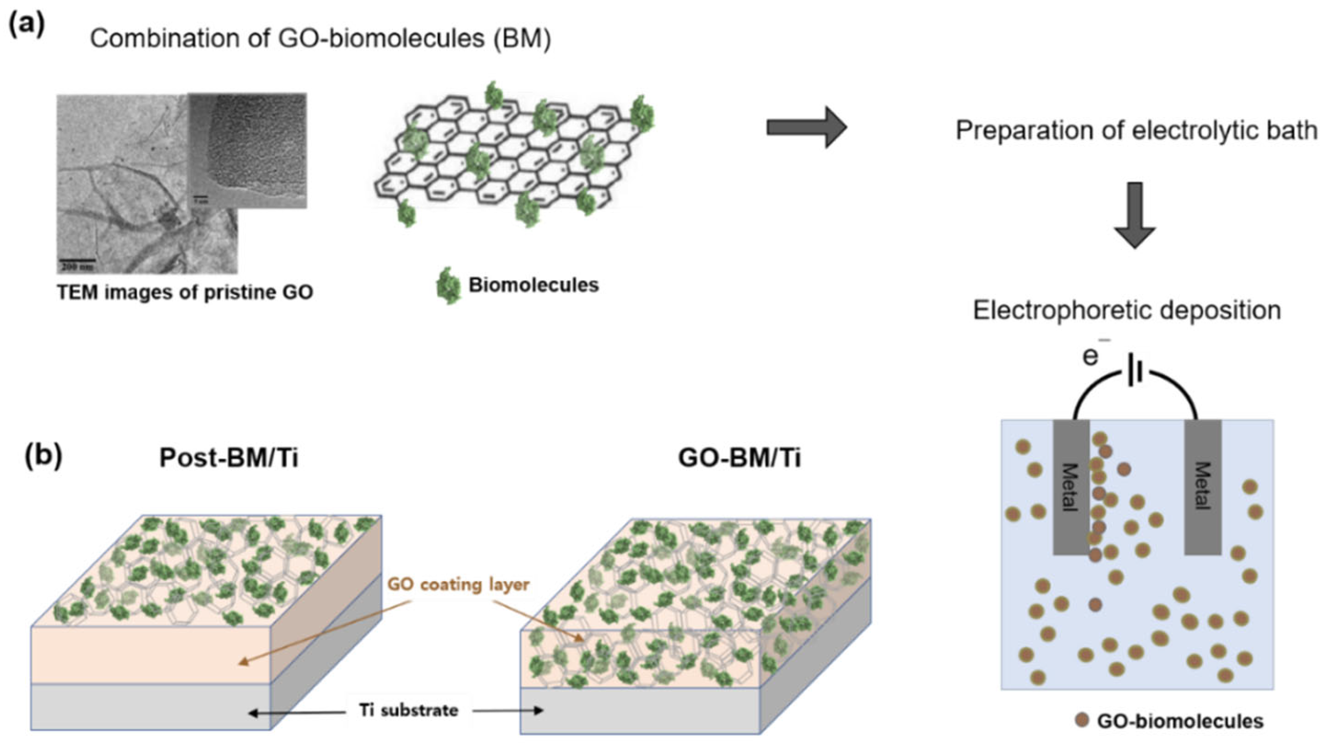
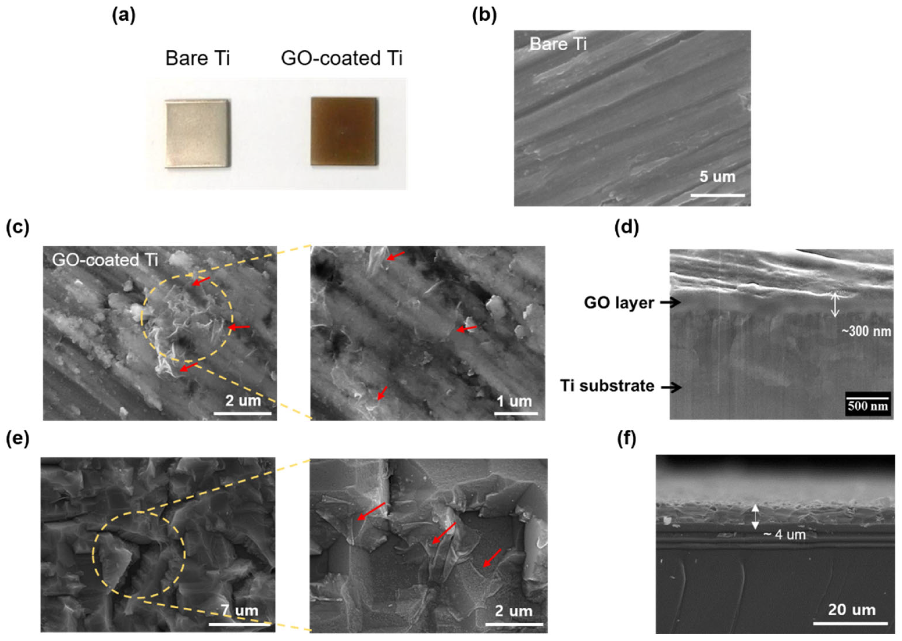
3.1. Preparation of GO-Coated Ti Plates

GO-coated Ti plates were prepared via EPD at room temperature. A schematic is shown in Figure 1a. Hydrophilic GO bound BMs between the many GO layers (Figure 1b) [31]. Prior to EPD, BM was conjugated onto GO sheets and the complexes were evenly dispersed in electrolytic baths with 80% (v/v) ethanol; EPD followed. The GO coatings thus contained internal BM. The schematic of Figure 1b shows how BM was attached after the GO coating. The GO coating thickness can be controlled when modifying metal implants; the coating can contain large amounts of BM. If the BM were to be exclusively surface-attached, a protective layer would be required. Our method removed the need for such a layer [32].

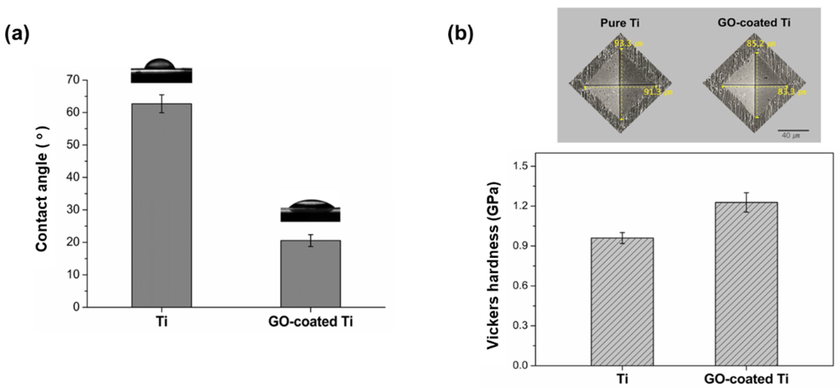
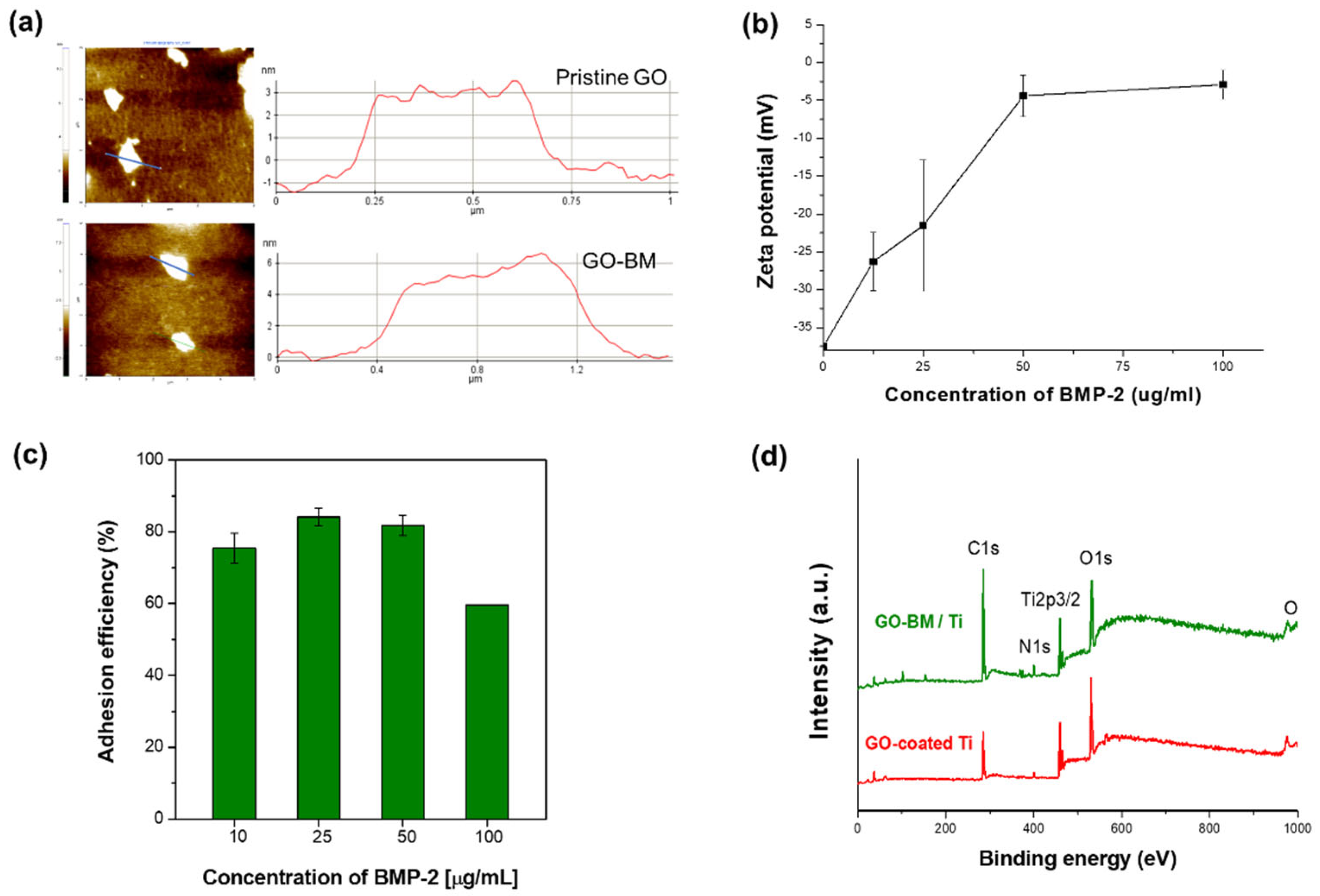
3.2. Characterization of GO-Coated Ti Plates

GO coating morphology and thickness depend on the EPD time, voltage, current, and GO concentration. Figure 2a shows photographs of bare Ti and GO-coated Ti plates. After EPD, the Ti substrate was uniformly covered with brown GO. Figure 2b,c,e shows SEM images of bare and GO-coated Ti plates; a short deposition time created thin films and a long deposition time created thick films.
Figure 2c,e shows the morphologies of (smooth) bare and GO-coated Ti plates. Cross-sections were prepared to measure coating thickness by EPD time. Increasing the time from 30 to 600 s increased the coating thickness. Figure 2d shows that the 30-s layer was less than 300 nm thick; Figure 2f shows that the 10-min thickness was approximately 4 μm.
The coated GO layer was analyzed by X-ray photon and Raman spectroscopy, and an X-ray diffraction analysis. The XPS spectra of GO-coated and bare Ti revealed titanium (Ti2p), oxygen (O1s), and carbon (C1s) (Figure 3a). The O1s peak was attributable to adsorbed hydroxides and oxides; both specimens showed peaks at 531.9 eV. The Ti2p3/2 oxide peak at 458.5 eV was typical of Ti. The C1s peak was most often used to measure oxide levels, but the peak was weak for bare Ti. The C1s of GO featured several binding energy configurations, at 284.8, 285.1, 286.3, and 288 eV for sp2, sp3, and the C-O (epoxy/hydroxyl), and O-C5O (carboxyl) groups, respectively. The sp2 carbon (284.8 eV) was the major feature of the C1s profile, indicating the presence of GO, which was generally identified by the three characteristic Raman G, D, and 2D bands [33]. The Raman spectrum of GO showed the D band (sp3) at 1350 cm−1 and 1344 cm−1 and the G band (sp2) at 1604 cm−1 and 1601 cm−1; bare Ti lacked these bands (Figure 3b) [34]. Figure 3c shows the XRD patterns. The typical diffraction peaks of Ti (those of the JCPDS card no. 44-1294) were observed. GO-coated Ti exhibited a broad peak at 26°, indicating between-graphene π–π stacking [35]. Hexagonal crystals of graphene or graphite were associated with characteristic peaks in the (002) and (111) planes [36]. Thus, GO clearly coated the Ti, and EPD rendered the coating uniform and thickness controllable.
Figure 4a,b shows the contact angle hydrophilicities and indentation hardness values, respectively. GO coating dramatically improved Ti hydrophilicity and hardness, reflecting the outstanding mechanical properties (Young’s modulus ~1 Ta) of GO [37,38,39]. When metal-based implants are transplanted, strong friction and shear stresses can damage their surfaces [40]. Many coatings have been used to strengthen the surfaces [41]. Here, we simply coated GO using EPD.

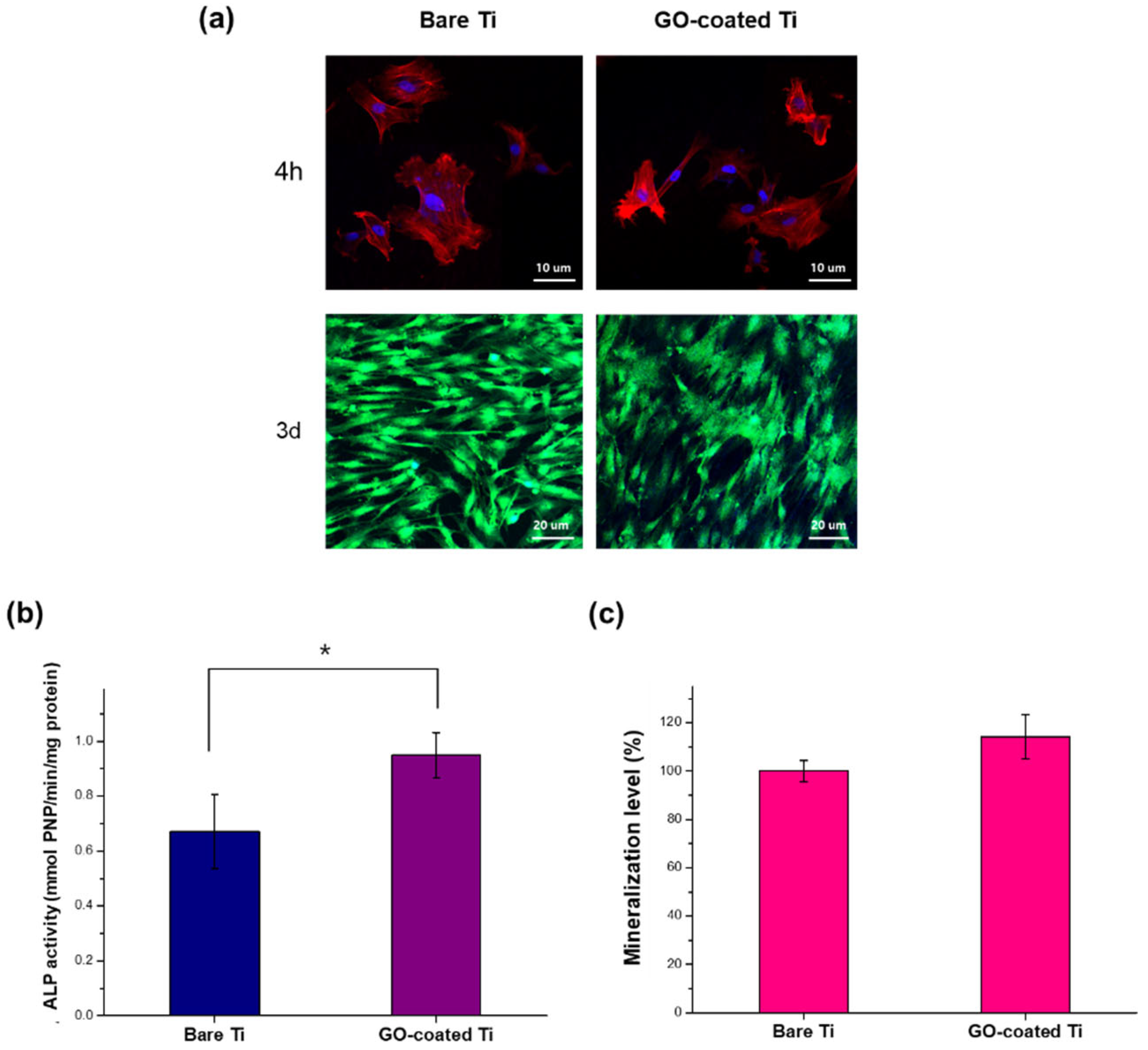
3.3. In Vitro Cellular Responses
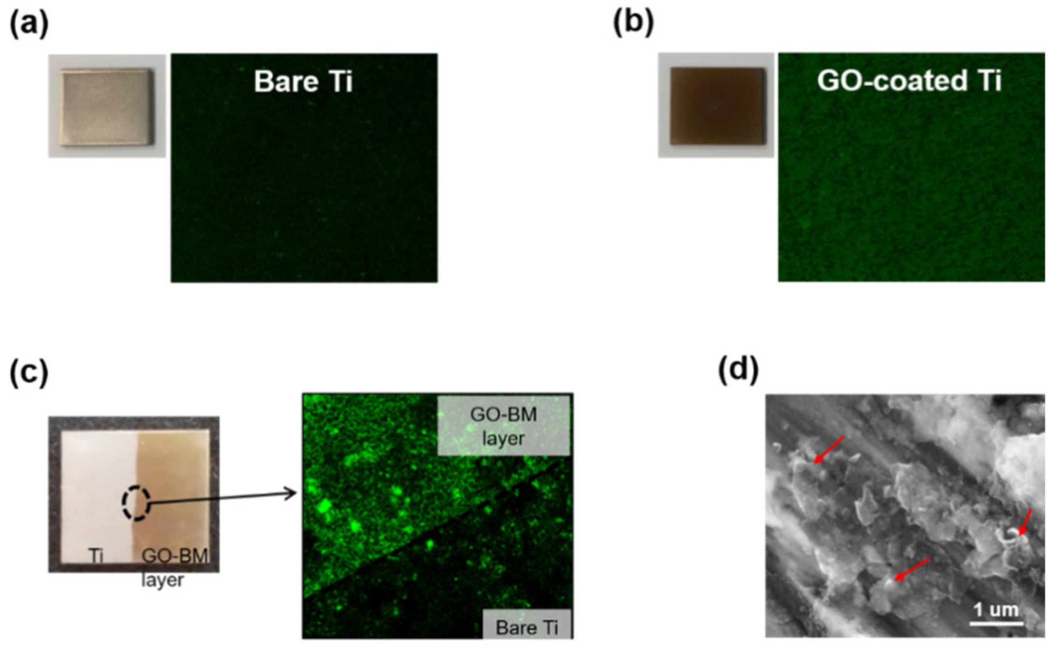
GO exhibited good biocompatibility and osteo-conductivity; we used CLSM to evaluate the effects of coating on stem cells, and the extents of ALP activity and mineralization compared to those of bare Ti [42,43,44]. Figure 5a shows CLSM images of cells cultured for 3 days. The cells were well attached, spread by 4 h, and grew over the 3 days. Neither cell attachment nor proliferation differed between the samples. To evaluate the initial (and later) osteogenic differentiation of stem cells cultured on a GO-EPD layer, cells were cultured for 7 and 14 days in a non-osteogenic culture medium. Cellular ALP activity was significantly enhanced by the GO coating. After 14 days of culture, the cellular calcium levels were measured (Figure 5c). Cells cultured on GO-coated Ti exhibited slightly more calcium deposition than those cultured on bare Ti. Not only was GO-coated Ti non-toxic but also GO facilitated early osteogenic differentiation [42,43,44].

3.4. BM-Loading GO

GO served as both the BMP-2 loading agent and the coating. 2D flaked GO readily binds BMs; the carbon honeycomb induces BM adsorption driven by the Van der Waals force [45]. After attachment of various levels of BMP-2 to GO, BMP-2 adhesion to GO was assessed by the AFM, the Zetasizer, ELISA, and XPS. An AFM is usually employed to measure graphene thickness. As shown in Figure 6a, a blue line across the single graphene is specified and the roughness of the specimen is measured along the line. Figure 6a shows the representative AFM images of pristine GO and BM-combined GO. The AFM analysis was performed to observe the thickness change of GO combined with BM (BMP-2). The Rz value of GO and GO-GM were 4.10 ± 0.26 nm and 5.74 ± 0.61 nm, respectively. This was an increase in thickness induced by BMP-2, indicating that GO and BMP-2 were well combined.
Figure 6b shows the zeta potentials of GO with different BMP-2 concentrations; all GO coatings were deposited on the positively charged electrode. The zeta potential confirmed that EPD was in play, and that the GO and BM combination was efficient. The negative GO potential facilitated BMP-2 attachment. At a high concentration of BMP-2, the GO-BM zeta potential became more electropositive. Thus, BMP-2 adsorption to GO increased with increasing BMP-2 concentration, but the GO-BM potential remained negative; there was no need to switch the EPD anode and cathode. Figure 6c shows that at concentrations of 25 and 50 μg/mL, approximately 85% of BMP-2 became attached; the absolute concentrations of unattached BMP-2 were approximately 3.7 and 7.5 μg/mL, respectively. To minimize BMP-2 wastage, we used a BMP-2 concentration of 25 μg/mL in subsequent experiments. XPS revealed the components of the GO-BM coating (Figure 6d). The C peak and O peak of GO-coated Ti and GO-BM-coated Ti appeared at 285 and 532 eV of binding energy, respectively. Compared to GO-coated Ti, GO-BM-coated Ti (Figure 6d) exhibited a higher N1s peak at 399 eV, attributable to the -C5N or -CN bonds caused by the N atom in the amino acid of BMP-2 [46,47].
The GO-BM (BMP-2) coating layer was evaluated in more detail using XPS (Table 1). Ti, C, O, and N were detected in bare Ti, and the GO and GO-BM coatings; however, the N atomic ratio was highest in the latter coating. While the Ti and O proportions fell significantly in the GO-BM coating, the C proportion was higher than those of other surfaces. Most biomolecules have amine and carboxyl groups; the N and C levels were thus highest in the GO-BM coating, indicating that EPD successfully formed such a coating [48].
EPD forms uniform coatings. We compared GO-GFP, GO-BM, GO-coated Ti, and bare Ti. Figure 7 shows BM adhesion both photographically and as revealed by CLSM (Figure 7a–c). Compared to bare Ti, GO-coated layers had weak green fluorescence. To observe the surface of GFP-containing GO, we used adhesive tape to separate the GO-BM coating from bare Ti. The CLSM boundary data of Figure 7c show that more green fluorescence emanated from the BM-coated region. The weak green fluorescence of bare Ti may indicate that the GO-BM (GFP) suspension penetrated the adhesive tape during EPD. Unlike the surface of GO-coated Ti, a surface coated with GO-BM exhibited strong fluorescence. SEM (Figure 7d) revealed aggregates (red arrows) on the GO-BM coating. The combination of two substances during GO-BM formation was associated with aggregation or sinkage. Thus, EPD featured continuous stirring that minimized sinkage but did not completely prevent aggregation. Therefore, the green fluorescent aggregates were thought to be GO-BM complexes.

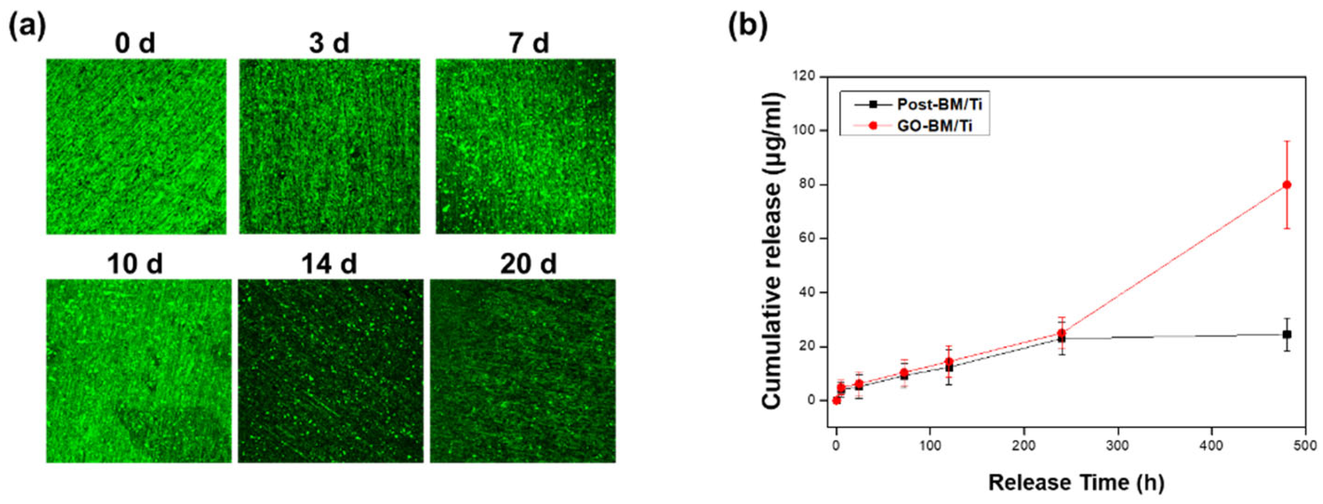
3.5. BM Release from GO-Coated Ti

BM release was assessed via CLSM and ELISA. Figure 8a shows fluorescence images of BM that remained in the GO-BM coating after soaking for various times in PBS. Over 20 days, the fluorescence intensity fell continuously, indicating sustained BM release from the GO-BM coating layer. Figure 8b shows the cumulative amounts of BM released over time. Ti exposed to BM after GO coating and Ti coated with the GO and BM combination are indicated by Post-BM and GO-BM respectively. BM was slowly and steadily released over an extended period. During up to 10 days (240 h) of analysis, both samples released similar amounts of BM. However, after 20 days, the total amounts of BM released from GO-BM/Ti and Post-BM/Ti were approximately 79.9 and 24.5 μg, respectively. CLSM revealed no significant reduction in fluorescence intensity during release up to 10 days; however, on day 14, major decreases in fluorescence intensity were evident, in line with the release profiles. After 10 days, BM was no longer released from the Post-BM/Ti sample; however, GO-BM/Ti then exhibited continued rapid BM release, unlike the previous steady release profile.
We found that BM pervaded the coating, and we demonstrated how to modify metal implants to ensure stable long-term BM release. The coating thickness controlled the amount and rate of BM release. Room temperature EPD coated undamaged BMs; it was easy to adjust the coating thickness. GO readily adsorbed BMs. High-quality coatings of varying (controllable) thickness formed rapidly. BM loadings were high, because the BMs were not (only) surface-attached.

4. Conclusions

We used EPD to modify metal surfaces to stably and slowly deliver BMs. GO coating increased surface hydrophilicity and hardness and ALP activity (a feature of osteogenic differentiation). Hydrophilic GO combined with BMs to form GO-BM complexes that uniformly coated a metal. Coatings with internal (not only surface-attached) BMs were optimal, and will find many applications in medicine.

Author Contributions

Conceptualization, E.-J.L.; methodology, J.-S.O. and J.-H.J.; investigation, E.-J.L., J.-S.O. and J.-H.J.; writing—original draft preparation, E.-J.L., J.-S.O. and J.-H.J.; writing—review and editing, E.-J.L., J.-S.O. and J.-H.J.; supervision, E.-J.L.; project administration, E.-J.L.; funding acquisition, E.-J.L. All authors have read and agreed to the published version of the manuscript.

Funding

This work was supported by the National Research Foundation of Korea (NRF), which is funded by the Ministry of Science and Information and Communications Technologies (MSIT; NRF-2018M3C1B7021994 and NRF-2020R1A2C1012454).

Data Availability Statement

Not applicable.

Acknowledgments

This work was supported by the National Research Foundation of Korea (NRF), which is funded by the Ministry of Science and Information and Communications Technologies (MSIT; NRF-2018M3C1B7021994 and NRF-2020R1A2C1012454).

Conflicts of Interest

The author(s) declared no potential conflicts of interest with respect to the research, authorship, and/or publication of this article.

References

  1. Alvarez, K.; Nakajima, H. Metallic scaffolds for bone regeneration. Materials 2009, 2, 790–832. [Google Scholar] [CrossRef]
  2. Pizzoferrato, A.; Cenni, E.; Ciapetti, G.; Granchi, D.; Savarino, L.; Stea, S. Inflammatory response to metals and ceramics. In Integrated Biomaterials Science; Barbucci, R., Ed.; Springer US: Boston, MA, USA, 2002; pp. 735–791. [Google Scholar]
  3. Shahali, H.; Jaggessar, A.; Yarlagadda, P.K.D.V. Recent advances in manufacturing and surface modification of titanium orthopaedic applications. Procedia Eng. 2017, 174, 1067–1076. [Google Scholar] [CrossRef] [Green Version]
  4. Dong, H.; Liu, H.; Zhou, N.; Li, Q.; Yang, G.; Chen, L.; Mou, Y. Surface modified techniques and emerging functional coating of dental implants. Coatings 2020, 10, 1012. [Google Scholar] [CrossRef]
  5. Kim, Y.-W. Surface modification of ti dental implants by grit-blasting and micro-arc oxidation. Mater. Manuf. Process. 2010, 25, 307–310. [Google Scholar] [CrossRef]
  6. López, V.; Sundaram, R.S.; Gómez-Navarro, C.; Olea, D.; Burghard, M.; Gómez-Herrero, J.; Zamora, F.; Kern, K. Chemical vapor deposition repair of graphene oxide: A route to highly-conductive graphene monolayers. Adv. Mater. 2009, 21, 4683–4686. [Google Scholar] [CrossRef]
  7. Vats, N.; Rauschenbach, S.; Sigle, W.; Sen, S.; Abb, S.; Portz, A.; Dürr, M.; Burghard, M.; van Aken, P.A.; Kern, K. Electron microscopy of polyoxometalate ions on graphene by electrospray ion beam deposition. Nanoscale 2018, 10, 4952–4961. [Google Scholar] [CrossRef] [PubMed] [Green Version]
  8. Terasawa, T.-O.; Saiki, K. Growth of graphene on cu by plasma enhanced chemical vapor deposition. Carbon 2012, 50, 869–874. [Google Scholar] [CrossRef]
  9. Wu, C.; Cheng, Q.; Sun, S.; Han, B. Templated patterning of graphene oxide using self-assembled monolayers. Carbon 2012, 50, 1083–1089. [Google Scholar] [CrossRef]
  10. Beutner, R.; Michael, J.; Schwenzer, B.; Scharnweber, D. Biological nano-functionalization of titanium-based biomaterial surfaces: A flexible toolbox. J. R. Soc. Interface 2010, 7, S93–S105. [Google Scholar] [CrossRef] [PubMed] [Green Version]
  11. Haimov, H.; Yosupov, N.; Pinchasov, G.; Juodzbalys, G. Bone morphogenetic protein coating on titanium implant surface: A systematic review. J. Oral. Maxillofac. Res. 2017, 8, e1. [Google Scholar] [CrossRef]
  12. Ajori, S.; Ameri, A.; Ansari, R. Adsorption analysis and mechanical characteristics of carbon nanotubes under physisorption of biological molecules in an aqueous environment using molecular dynamics simulations. Mol. Simul. 2020, 46, 388–397. [Google Scholar] [CrossRef]
  13. Ouyang, L.; Deng, Y.; Yang, L.; Shi, X.; Dong, T.; Tai, Y.; Yang, W.; Chen, Z.-G. Graphene-oxide-decorated microporous polyetheretherketone with superior antibacterial capability and in vitro osteogenesis for orthopedic implant. Macromol. Biosci. 2018, 18, 1800036. [Google Scholar] [CrossRef]
  14. Zhao, C.; Lu, X.; Zanden, C.; Liu, J. The promising application of graphene oxide as coating materials in orthopedic implants: Preparation, characterization and cell behavior. Biomed. Mater. 2015, 10, 015019. [Google Scholar] [CrossRef] [PubMed]
  15. Hirata, E.; Ménard-Moyon, C.; Venturelli, E.; Takita, H.; Watari, F.; Bianco, A.; Yokoyama, A. Carbon nanotubes functionalized with fibroblast growth factor accelerate proliferation of bone marrow-derived stromal cells and bone formation. Nanotechnology 2013, 24, 435101. [Google Scholar] [CrossRef] [PubMed]
  16. La, W.-G.; Park, S.; Yoon, H.-H.; Jeong, G.-J.; Lee, T.-J.; Bhang, S.H.; Han, J.Y.; Char, K.; Kim, B.-S. Delivery of a therapeutic protein for bone regeneration from a substrate coated with graphene oxide. Small 2013, 9, 4051–4060. [Google Scholar] [CrossRef] [PubMed]
  17. Oh, J.-S.; Lee, E.-J. Enhanced effect of polyethyleneimine-modified graphene oxide and simvastatin on osteogenic differentiation of murine bone marrow-derived mesenchymal stem cells. Biomedicines 2021, 9, 501. [Google Scholar] [CrossRef]
  18. Wu, J.; Zheng, A.; Liu, Y.; Jiao, D.; Zeng, D.; Wang, X.; Cao, L.; Jiang, X. Enhanced bone regeneration of the silk fibroin electrospun scaffolds through the modification of the graphene oxide functionalized by bmp-2 peptide. Int. J. Nanomed. 2019, 14, 733–751. [Google Scholar] [CrossRef] [Green Version]
  19. Saladino, M.L.; Markowska, M.; Carmone, C.; Cancemi, P.; Alduina, R.; Presentato, A.; Scaffaro, R.; Biały, D.; Hasiak, M.; Hreniak, D.; et al. Graphene oxide carboxymethylcellulose nanocomposite for dressing materials. Materials 2020, 13, 1980. [Google Scholar] [CrossRef]
  20. Li, H.; Gao, C.; Tang, L.; Wang, C.; Chen, Q.; Zheng, Q.; Yang, S.; Sheng, S.; Zan, X. Lysozyme (lys), tannic acid (ta), and graphene oxide (go) thin coating for antibacterial and enhanced osteogenesis. ACS Appl. Bio Mater. 2020, 3, 673–684. [Google Scholar] [CrossRef] [Green Version]
  21. Han, L.; Sun, H.; Tang, P.; Li, P.; Xie, C.; Wang, M.; Wang, K.; Weng, J.; Tan, H.; Ren, F.; et al. Mussel-inspired graphene oxide nanosheet-enwrapped ti scaffolds with drug-encapsulated gelatin microspheres for bone regeneration. Biomater. Sci. 2018, 6, 538–549. [Google Scholar] [CrossRef]
  22. Oliver, J.-A.N.; Su, Y.; Lu, X.; Kuo, P.-H.; Du, J.; Zhu, D. Bioactive glass coatings on metallic implants for biomedical applications. Bioact. Mater. 2019, 4, 261–270. [Google Scholar] [CrossRef]
  23. Santoro, M.; Tatara, A.M.; Mikos, A.G. Gelatin carriers for drug and cell delivery in tissue engineering. J. Control. Release 2014, 190, 210–218. [Google Scholar] [CrossRef] [PubMed] [Green Version]
  24. Fox, K.E.; Tran, N.L.; Nguyen, T.A.; Nguyen, T.T.; Tran, P.A. 8—surface modification of medical devices at nanoscale—recent development and translational perspectives. In Biomaterials in Translational Medicine; Yang, L., Bhaduri, S.B., Webster, T.J., Eds.; Academic Press: Cambridge, MA, USA, 2019; pp. 163–189. [Google Scholar]
  25. Besra, L.; Liu, M. A review on fundamentals and applications of electrophoretic deposition (epd). Prog. Mater. Sci. 2007, 52, 1–61. [Google Scholar] [CrossRef]
  26. Ma, Y.; Han, J.; Wang, M.; Chen, X.; Jia, S. Electrophoretic deposition of graphene-based materials: A review of materials and their applications. J. Mater. 2018, 4, 108–120. [Google Scholar] [CrossRef]
  27. Mallick, M.; Arunachalam, N. Electrophoretic deposited graphene based functional coatings for biocompatibility improvement of nitinol. Thin Solid Films 2019, 692, 137616. [Google Scholar] [CrossRef]
  28. Eshghinejad, P.; Farnoush, H.; Bahrami, M.S.; Bakhsheshi-Rad, H.R.; Karamian, E.; Chen, X.B. Electrophoretic deposition of bioglass/graphene oxide composite on ti-alloy implants for improved antibacterial and cytocompatible properties. Mater. Technol. 2020, 35, 69–74. [Google Scholar] [CrossRef]
  29. Mehrali, M.; Akhiani, A.R.; Talebian, S.; Mehrali, M.; Latibari, S.T.; Dolatshahi-Pirouz, A.; Metselaar, H.S.C. Electrophoretic deposition of calcium silicate–reduced graphene oxide composites on titanium substrate. J. Eur. Ceram. Soc. 2016, 36, 319–332. [Google Scholar] [CrossRef] [Green Version]
  30. Shi, Y.Y.; Li, M.; Liu, Q.; Jia, Z.J.; Xu, X.C.; Cheng, Y.; Zheng, Y.F. Electrophoretic deposition of graphene oxide reinforced chitosan–hydroxyapatite nanocomposite coatings on ti substrate. J. Mater. Sci. Mater. Med. 2016, 27, 48. [Google Scholar] [CrossRef] [PubMed]
  31. Sharma, H.; Mondal, S. Functionalized graphene oxide for chemotherapeutic drug delivery and cancer treatment: A promising material in nanomedicine. Int. J. Mol. Sci. 2020, 21, 6280. [Google Scholar] [CrossRef]
  32. Rykowska, I.; Nowak, I.; Nowak, R. Drug-eluting stents and balloons-materials, structure designs, and coating techniques: A review. Molecules 2020, 25, 4624. [Google Scholar] [CrossRef]
  33. Kovtun, A.; Jones, D.; Dell’Elce, S.; Treossi, E.; Liscio, A.; Palermo, V. Accurate chemical analysis of oxygenated graphene-based materials using x-ray photoelectron spectroscopy. Carbon 2019, 143, 268–275. [Google Scholar] [CrossRef] [Green Version]
  34. Qin, H.; Gong, T.; Cho, Y.; Lee, C.; Kim, T. A conductive copolymer of graphene oxide/poly(1-(3-aminopropyl)pyrrole) and the adsorption of metal ions. Polym. Chem. 2014, 5, 4466–4473. [Google Scholar] [CrossRef]
  35. Karthik, P.; Vinoth, R.; Zhang, P.; Choi, W.; Balaraman, E.; Neppolian, B. Π–π interaction between metal–organic framework and reduced graphene oxide for visible-light photocatalytic h2 production. ACS Appl. Energy Mater. 2018, 1, 1913–1923. [Google Scholar] [CrossRef]
  36. Xu, X.; Li, W.; Wang, Y.; Dong, G.; Jing, S.; Wang, Q.; Feng, Y.; Fan, X.; Ding, H. Study of the preparation of cu-tic composites by reaction of soluble ti and ball-milled carbon coating tic. Results Phys. 2018, 9, 486–492. [Google Scholar] [CrossRef]
  37. Hwang, M.-J.; Kim, M.-G.; Kim, S.; Kim, Y.C.; Seo, H.W.; Cho, J.K.; Park, I.-K.; Suhr, J.; Moon, H.; Koo, J.C.; et al. Cathodic electrophoretic deposition (epd) of phenylenediamine-modified graphene oxide (go) for anti-corrosion protection of metal surfaces. Carbon 2019, 142, 68–77. [Google Scholar] [CrossRef]
  38. Zielinski, A.; Bartmanski, M. Electrodeposited biocoatings, their properties and fabrication technologies: A review. Coatings 2020, 10, 782. [Google Scholar] [CrossRef]
  39. Nemee, P.; Jaitanong, N.; Narksitipan, S. Surface modification of low carbon steel by using electrophoretic deposition technique with graphene oxide powder. Solid State Phenom. 2020, 302, 1–7. [Google Scholar] [CrossRef]
  40. Shayesteh Moghaddam, N.; Taheri Andani, M.; Amerinatanzi, A.; Haberland, C.; Huff, S.; Miller, M.; Elahinia, M.; Dean, D. Metals for bone implants: Safety, design, and efficacy. Biomanuf. Rev. 2016, 1, 1. [Google Scholar] [CrossRef]
  41. Dehghanghadikolaei, A.; Fotovvati, B. Coating techniques for functional enhancement of metal implants for bone replacement: A review. Materials 2019, 12, 1795. [Google Scholar] [CrossRef] [Green Version]
  42. Su, J.; Du, Z.; Xiao, L.; Wei, F.; Yang, Y.; Li, M.; Qiu, Y.; Liu, J.; Chen, J.; Xiao, Y. Graphene oxide coated titanium surfaces with osteoimmunomodulatory role to enhance osteogenesis. Mater. Sci. Eng. C 2020, 113, 110983. [Google Scholar] [CrossRef]
  43. Qiu, J.; Geng, H.; Wang, D.; Qian, S.; Zhu, H.; Qiao, Y.; Qian, W.; Liu, X. Layer-number dependent antibacterial and osteogenic behaviors of graphene oxide electrophoretic deposited on titanium. ACS Appl. Mater. Interfaces 2017, 9, 12253–12263. [Google Scholar] [CrossRef] [PubMed]
  44. Tao, B.; Chen, M.; Lin, C.; Lu, L.; Yuan, Z.; Liu, J.; Liao, Q.; Xia, Z.; Peng, Z.; Cai, K. Zn-incorporation with graphene oxide on ti substrates surface to improve osteogenic activity and inhibit bacterial adhesion. J. Biomed. Mater. Res. A 2019, 107, 2310–2326. [Google Scholar] [CrossRef]
  45. Allen, M.J.; Tung, V.C.; Kaner, R.B. Honeycomb carbon: A review of graphene. Chem. Rev. 2010, 110, 132–145. [Google Scholar] [CrossRef]
  46. Song, M.-J.; Amirian, J.; Linh, N.T.B.; Lee, B.-T. Bone morphogenetic protein-2 immobilization on porous pcl-bcp-col composite scaffolds for bone tissue engineering. J. Appl. Polym. Sci. 2017, 134, 45186. [Google Scholar] [CrossRef]
  47. Pugalenthi, R.; Arunachalam, P.; Amalraj, S.; Rathinavel, J.; Subramaniyan, D.S.; Bhagavathsingh, J.; Samuel, V. Covalent grafting of n-containing compound with graphene oxide: Efficient electrode material for supercapacitor. Chem. Sci. Eng. Res. 2019, 1. [Google Scholar] [CrossRef]
  48. Liang, X.; Zhong, J.; Shi, Y.; Guo, J.; Huang, G.; Hong, C.; Zhao, Y. Hydrothermal synthesis of highly nitrogen-doped few-layer graphene via solid–gas reaction. Mater. Res. Bull. 2015, 61, 252–258. [Google Scholar] [CrossRef]
Figure 1. Schematic diagram of electrophoretic deposition (a). The coating layers termed Post-BM/Ti and GO-BM/Ti (b).
Metals 11 00899 g001
Figure 2. Optical surface images (a). SEM image of a bare Ti surface (b). Images of Ti plates coated thinly and thickly with GO (the arrows indicate GO flakes) (c,e). Cross-sectional views of thin and thick GO coatings (d,f).
Metals 11 00899 g002
Figure 3. EPD characterization of GO-coated Ti and bare Ti. XPS spectra (a). Raman spectra (b). XRD patterns (c).
Metals 11 00899 g003
Figure 4. Contact angles (a) and Vickers hardness values (b) of bare and GO-coated Ti (p < 0.05).
Metals 11 00899 g004
Figure 5. In vitro cell test results. Cell attachment revealed by CLSM (a). Alkaline phosphatase (ALP) activity of mMSCs after 7 days of culture (b). Alizarin Red S (ARS) staining after 21 days of culture (* p < 0.05) (c).
Metals 11 00899 g005
Figure 6. AFM observations of pristine GO and BM-combined GO (GO-BM) (a). The zeta potential of BM-combined GO as a function of the BMP-2 concentration (b). Characterization of GO-BM combinations by ELISA (c). XPS spectra of Ti with GO-BM coatings (GO-BM/Ti) and GO-coated Ti (d). The BM indicates BMP-2.
Metals 11 00899 g006
Figure 7. Optical and CLSM images of BM attachment: bare Ti (a), GO-coated Ti (b), and GO-BM/Ti (c). CLSM evaluation of GO-BM/Ti was performed on a region with a GO-BM layer and a region of bare Ti. SEM image of Ti with a GO-BM coating (d). The BM indicates GFP.
Metals 11 00899 g007
Figure 8. Release behaviors of BM (GFP). CLSM fluorescence images of BM remaining in GO-BM/Ti (a). BM release profiles over time (b).
Metals 11 00899 g008
Table 1. XPS component analyses of coating layers.
Amount (At. %)Bare TiGOGO-BM
Ti13.459.885.1
C44.5751.364.5
O39.7935.6926.59
N2.173.133.82
Publisher’s Note: MDPI stays neutral with regard to jurisdictional claims in published maps and institutional affiliations.

