Article

Deformation Characteristics and Microstructure Analysis of Aluminum Alloy Component with Complex Shape by Cold Orbital Forming

1
School of Materials Science and Engineering, Wuhan University of Technology, Wuhan 430070, China
2
Hubei Key Laboratory of Advanced Technology for Automotive Components, Wuhan 430070, China
3
Hubei Engineering Research Center for Green Precision Material Forming, Wuhan 430070, China
*
Author to whom correspondence should be addressed.
Metals 2021, 11(5), 808; https://doi.org/10.3390/met11050808
Submission received: 8 April 2021 / Revised: 12 May 2021 / Accepted: 13 May 2021 / Published: 16 May 2021
(This article belongs to the Special Issue Forming of Aluminium Alloys)

Abstract

:
This work aimed to study the deformation characteristics and microstructure of AA6063 aluminum alloy component with complex shape manufactured by cold orbital forming processing. The material flowing behavior was analyzed by Finite Element (FE) simulation and forming experiments were carried out using bar blank with different lengths. The microstructure of the boss zone cut from the formed samples was observed using scanning electron microscopy (SEM) and electron back-scatter diffraction (EBSD). FE simulation and experiment results both showed the aluminum base can be formed using cold orbital forming process. The distributions of the effective strain of the component with different blank lengths were almost the same, and the effective strain was bigger at the boss and the flash as the forming finished. The material flow is complex, especially in the boss, and the folding defect was observed at the root of the boss. The distribution of Mg2Si strengthening precipitate is more homogeneous in the matrix, has a different shape, and shows directivity at different position of boss zone. The grains are elongated, and the extent is different at different positions of the boss zone after cold orbital forming, and the crystal orientation discrepancy is smaller in the component main body and bigger in the boss zone. Subsequent forming process and blank optimization need to be further researched to improve forming quality.

1. Introduction

A lot of aluminum components with side branch and boss are applied more and more widely in the automobile and aerospace industries to decrease weight and increase strength. It is difficult to form the complex shape, and the forming load is large when using a conventional forging process. Therefore, an innovative method to manufacture the aluminum alloy component with complex shape using cold orbital forming process was proposed.
Cold orbital forming is a continuous metal plasticity forming process with local loading that can produce complex components. During cold orbital forming process, the punch partially contacts with the blank, which reduces the contact area between the punch and the blank, thereby decomposing the entire deformation process of the blank into continuous small deformations; thus, the forming load is greatly reduced under the same process conditions [1], and the metal fluidity is superior [2].
At present, some researchers made great efforts to study the theory, equipment, and application of cold rotary forming owing to its many advantages. Standring et al. [3] summarized the change of the angle of inclination along the tool axis during the entire deformation and developed an advanced orbital forging system without skidding or slipping, and they also calculated four types of punch paths (circular, straight line, spiral, and planet). Gu et al. [4] studied the static and dynamic performance of a 6300 KN cold orbital forging machine. Feng et al. [5] studied the influence of eccentricity on movements of orbital head with inner and outer eccentric sleeves in orbital forging. Loyda [6] explored the influence of the processing parameters on the microstructural evolution during hot orbital forging of a nickel-based superalloy disc. Hetzel et al. [7] combined local short term preheat treatment with preform to improve material flow in cold orbital forming. Grosman et al. [8] proposed an incremental deformation method for orbital forming of components with a complex upper surface. Samolyk [9] presented cold orbital forging of aluminum alloy bevel gears using FE simulation and verified by experiment. Sheu et al. [10] performed the die stress analysis of the orbital forging process to prevent the die failure and product defects. Qin [11] revealed contact mechanisms between the dies and the workpiece through modeling and simulation. Zhuang et al [12] studied the effect of key factors on the final step during cold orbital forging of a spur bevel gear. Jiang [13] concluded that the hot rotary forging could remarkably promote formability of Ti-6Al-4V alloy component by observing the microstructure and texture of rotary forged sample. Hua and Han [14] revealed the contact pressure response in a complicated metal forming technology of cold orbital forming by FE methods and explored the effects of friction coefficient on the metal flow and materials forming limit.
Moreover, Han et al. [15,16,17,18,19] researched cold orbital forming of complex nonrotating components and proposed a method for accurately designing the nonrotating punch based on the punch motion equation. Milutinovic et al. [20] analyzed and compared mechanical properties of a nonaxisymmetric steel U-cross joint component manufactured by cold orbital forging and conventional hot forging and found that the component formed by orbital forging showed better mechanical properties than the component manufactured by conventional forging. Also, cold orbital forging can be utilized for riveting assembly, such as the assembly of wheel hub bearing [21,22] and artificial joints production [23]. Recently, a novel orbital forming process called ultrasonic orbital microforming (UOM) was developed to form metal components whose dimensions were smaller than 1 mm [24,25].
Although cold orbital forming of complex nonrotating components were researched in recent years, there are few reports about deformation characteristics or the potential forming defects analysis and microstructure during cold orbital forming of the nonrotating component with side branch and boss. In this paper, which involves a complex AA6063 aluminum alloy component with side branch and boss structure for electric pruning scissors as shown in Figure 1, the cold orbital forming scheme for manufacturing the aluminum alloy component with complex shape was designed using a bar as the blank, then the FE model was established and the forming characteristics were analyzed. Subsequently, the forming experiment was carried out at T630 rotary forging press using three bar blanks with the same diameter and different length. FE simulation results and experimental results were compared to verify the feasibility of FE model. The precipitates and microstructure of the boss zone cut from the formed samples were observed using scanning electron microscopy (SEM) and electron back-scatter diffraction (EBSD) to understand more about the forming characteristics of an aluminum alloy component with complex shape using cold orbital forming processing.

2. Materials and Methods

2.1. Materials

In this paper, the material of the complex component is AA6063 aluminum alloy, which belongs to Al-Mg-Si deformed aluminum alloy, has good physical properties, and is used widely in various engineering fields to develop lightweight industrial products [26,27]. Its chemical composition (wt. %) is as follows: Si—0.2~0.6%, Mg—0.45~0.9%, Fe—0.35%, Mn—0.1%, Cr—0.1%, Zn—0.1%, Ti—0.1%, Cu—0.1%, and Al—for the remainder. The yield strength and tensile strength are 80 MPa and 150 MPa, respectively. Young’s modulus and Poisson’s ratio are 68.9 GPa and 0.33 GPa, respectively. The constitutive equation of the material treated after full annealing (O state) was obtained by carrying out tensile test and fitting experimental data and is expressed as follows [27]:
σ ¯ = 228 × ε ¯ 0.21

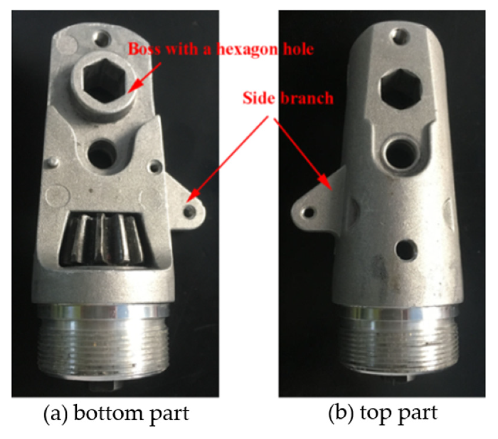
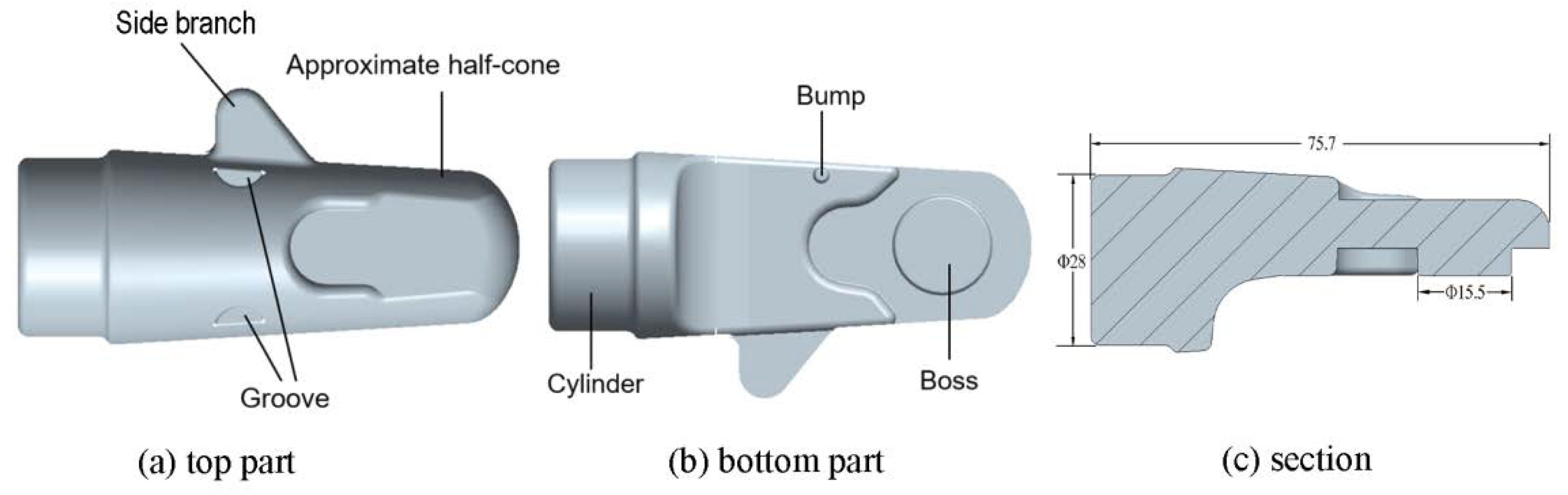
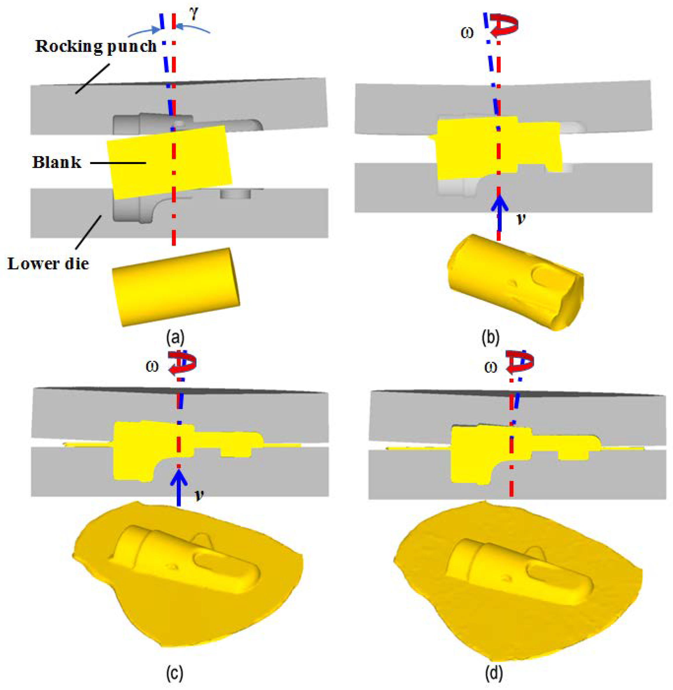
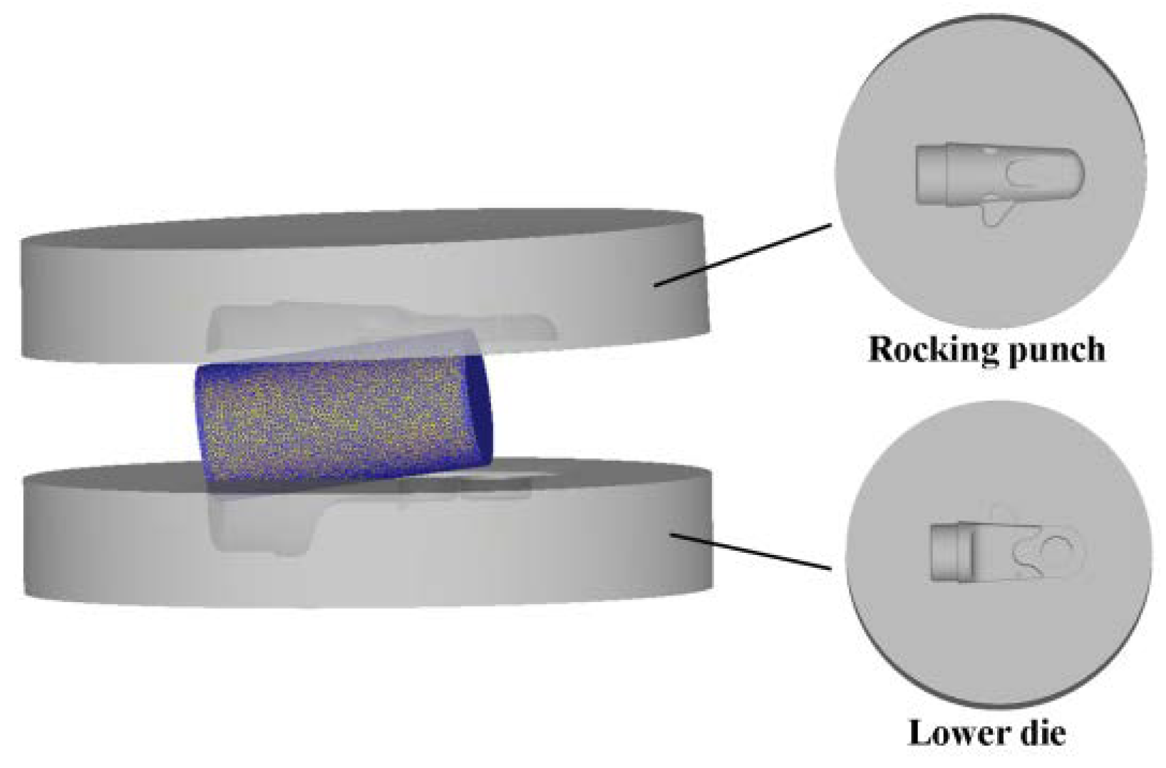
2.2. Cold Orbital Forming Scheme of Aluminum Alloy Compoent with Complex Shape

Figure 2 shows the 3D solid model of the forging for the aluminum alloy component with complex shape in question. It can be divided into two main structural parts; namely, an approximate cylinder and a half-cone, a side branch and the boss on the half-cone. The boss plays a significant role during assembly of the base and two blades. The component is a nonrotating complex part with a total length of 75.7 mm, and the length and diameter of the left cylinder end are 14 mm and 28 mm, respectively. The thickness and maximum length of the side branch are 3.7 mm and 7 mm, respectively. The height and diameter of the boss on the bottom right end are 4.5 mm and 15.5 mm, respectively. Cold orbital forming process of the aluminum alloy component with complex shape is proposed according to its structural characteristics.
Figure 3 shows the schematic diagram of cold orbital forming of the aluminum alloy component with complex shape. As shown in Figure 3, the whole forming process can be divided into orbital forming stages and the shaping stage. During the orbital forming stage, the rocking punch takes a rocking motion at angular velocity ω around a vertical axis at a fixed incline angle γ (usually between 1° and 3°), and meanwhile, the lower die feeds upward vertically at a fixed speed v. The blank deforms under the pressure of the rocking punch and the lower cavity and flows into the die cavities until the required shape is formed. During the shaping stage, the rocking punch still performs the rocking motion, but the lower die stops feeding and remains stationary to make the component form with superior quality.
According to Figure 2, the shape of the base is similar to a short shaft, thus, a bar is chosen as the blank. Considering the complex shape of pruning scissor base, especially the lateral branch with flattened and thin structure, the flash with a thickness of 1.36 mm was designed, and the volume of the blank was determined to be ~30–40% larger than the volume of component. The diameter of the blank was determined to be about 30 mm because the left end of the component was a cylinder with a diameter of ~28 mm. Thus, the length of bar blank can be decided according to the constancy of volume. Here, three types of bar blank with different lengths were designed, and their values were 55 mm, 58 mm, and 60 mm, respectively.
To make the bar maintain a stable position in the lower die during the forming process, the lower die must be deep enough. The structure of the rocking punch should be as simple as possible to reduce the design and production difficulties of the rocking punch. Because the cavity forming the top part of the forging is too shallow and the shape of the top part is much more complex than that of the bottom part, the top part of the forging is arranged to be formed by the rocking punch while the bottom part with boss is arranged to be formed by the lower die in this paper, as shown in Figure 3.
It is worth noting that the top part of the component is non-axisymmetric, different from the conventional rocking punch design method for axisymmetric components; the corresponding rocking punch is also non-axisymmetric. Moreover, the rocking punch performs a complex rocking motion during the formation process; thus, designing the non-axisymmetric rocking punch is a key issue. To deal with this problem, a novel method of designing the rocking punch that can form the non-axisymmetric component in cold orbital forming was developed by Han [15]. According to the design, the instantaneous geometric relation of contact surface between the non-axisymmetric component and the corresponding rocking punch was calculated and the complex non-axisymmetric rocking punch for cold orbital forming of the aluminum alloy component was designed accurately. Next, the lower die can be modeled using a reverse engineering method according to the geometric dimensions of the component using CAD software. Figure 4 shows the 3D solid models of the rocking punch and lower die built using Geomagic Wrap software (Geomagic Wrap 2015 Geomagic, Morrisville, NC, USA) and UG software (UG NX 8.5 Siemens PLM software, Munich, Germany). In addition, all angles of the models are rounded to avoid the mesh distortion in the FE simulation.

2.3. Establishment of FE Models

To analyze the forming characteristics during cold orbital forming of the aluminum alloy component with complex shape, corresponding 3D FE models were developed using Deform-3D software (Ver11.0 SFTC, Columbus, OH, USA), as shown in Figure 5.
Firstly, the 3D model of the bar blank, the rocking punch, and the lower die built in UG software were imported into Deform-3D software. Then, the deformed bar blank was defined as the deformed body and was discretized into about 31,680 nodes and 150,200 tetrahedral elements, and an automatic remeshing technique was adopted during simulation. The elastic deformation is negligible, and the rocking punch and the lower die are regarded as the rigid body. The rocking punch is set to make a circular rocking motion around the vertical axis and the value is 25.12 rad/s, while the lower die feeds upward at a constant speed and the value is 4 mm/s during the orbital forming stage and 0 during shaping stage. According to the location relation and movement relation among the rocking punch, the lower die, and the bar blank, the total simulation step was designed to be 741 and the step increment per step was controlled by time, whose value was prescribed to be 0.01, and the shaping time was defined as 1 s, so the total forming time is 7.41 s and the orbital forming time is 6.41 s.
In this paper, the component material is AA6063 aluminum alloy, and its constitutive equation expressed by Equation (1) and mechanical property shown in Section 2.1 were imported into Deform-3D software in the simulation.
The frictional models between the blank and punches were a constant shear friction model, and the empirical friction factor of 0.2 was designed to simplify the complex contact condition [28]. The simulation parameters and their values during the simulation of cold orbital forming of the component with complex shape are shown in Table 1.

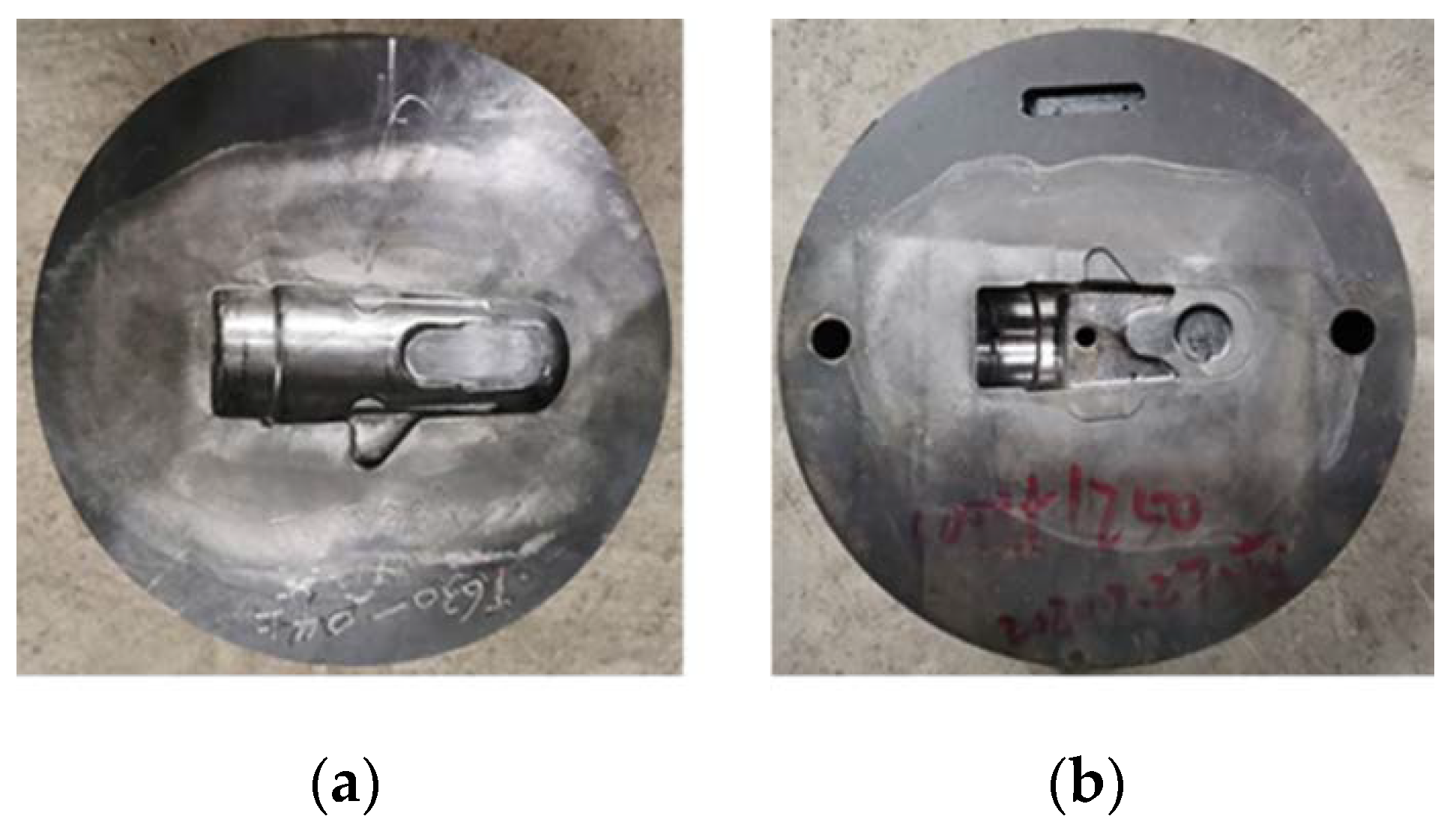
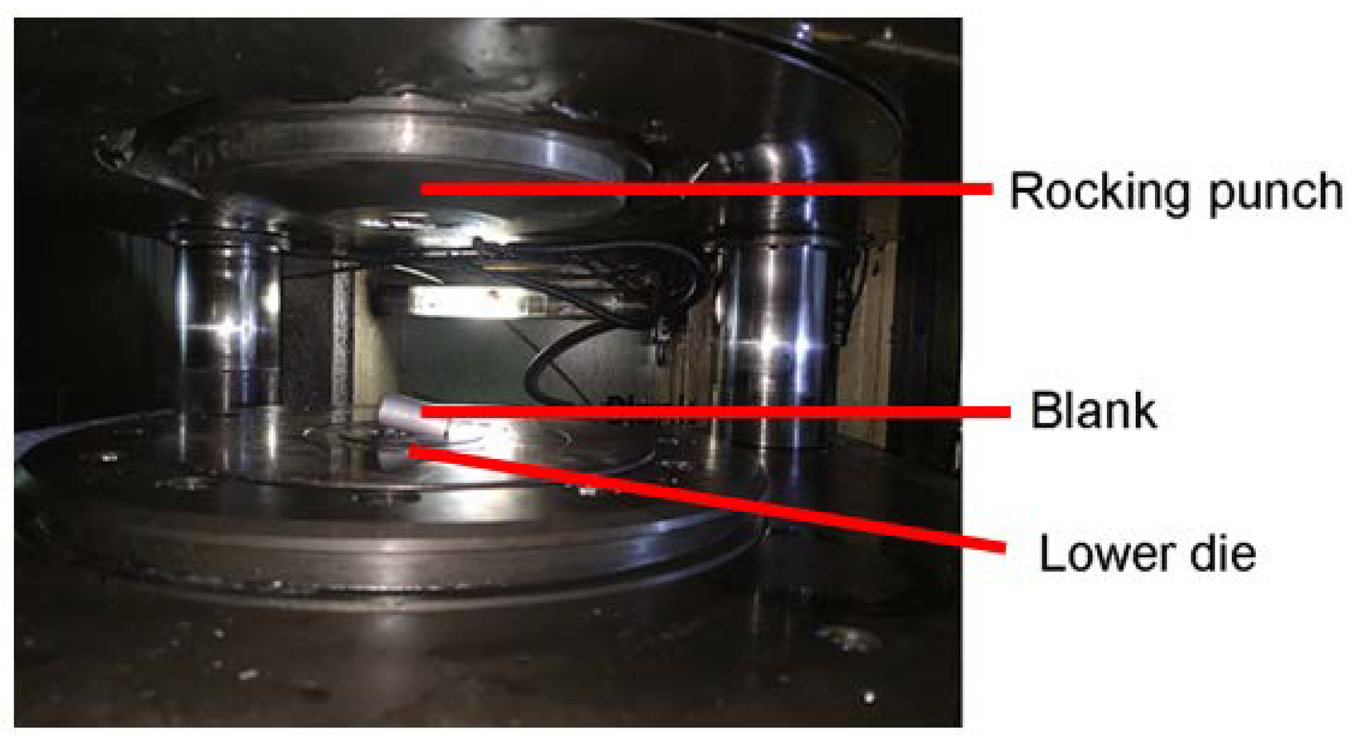
2.4. Cold Orbital Forming Experiment

To verify the reliability of the FE simulation, cold orbital forming experiments of aluminum alloy component with complex shape were performed. Firstly, three different bar blanks of the same dimensions as the 3D FE model, Φ30 mm × 55 mm, Φ30 mm × 58 mm and Φ30 mm × 60 mm, were manufactured using AA6063 aluminum alloy, respectively. Then, the rocking punch and the lower die were manufactured using LD (7Cr7Mo2V2Si) cold tool steel, as shown in Figure 6, and MoS2 lubricant was used to decrease the friction between the tools and blank during forming. Next, cold orbital forming experiments were conducted using T630 rotary forging machine (Schmid Co., Lyss, Switzerland), as shown in Figure 7.

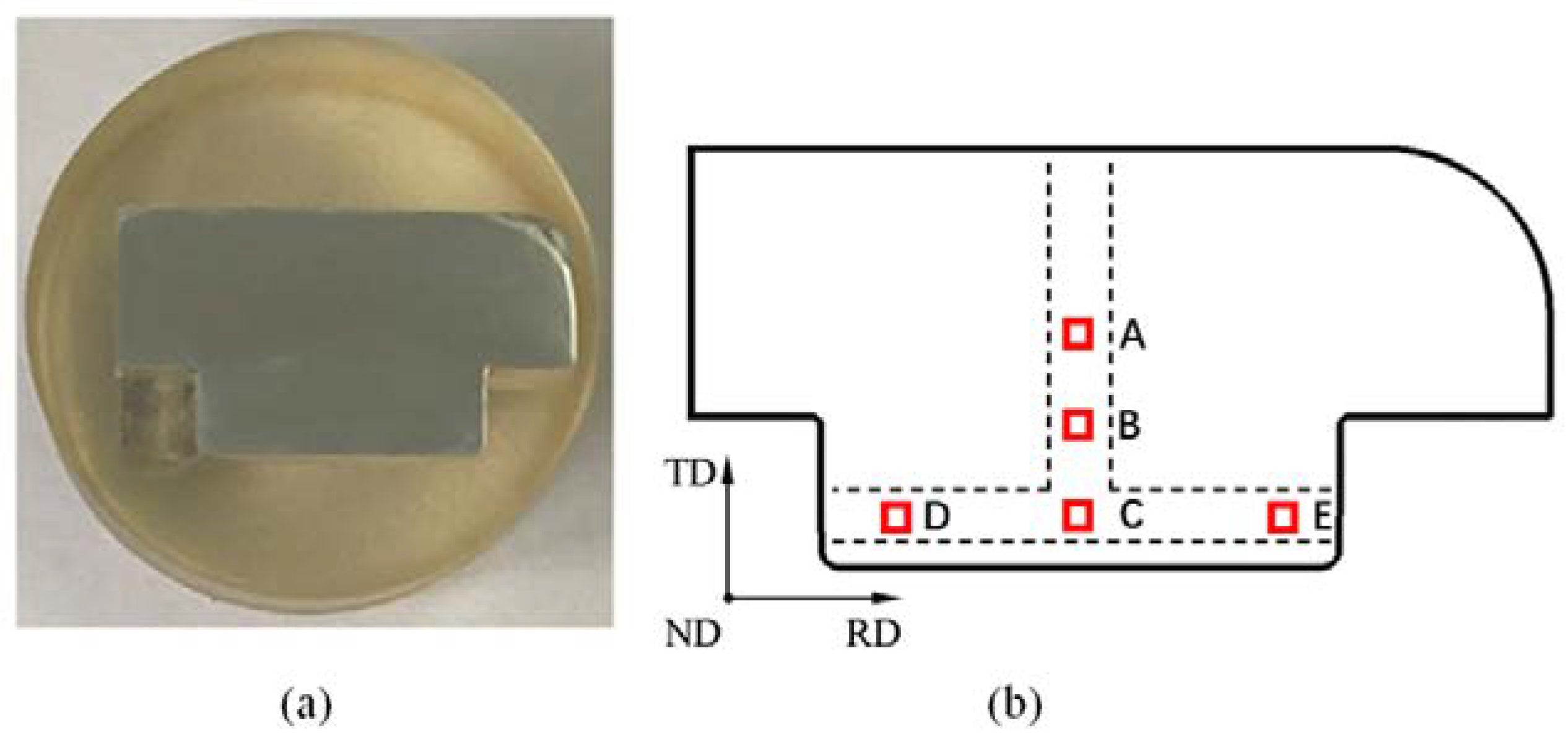
2.5. Analysis of Microstructure

In this paper, the microstructure analysis was carried out only for the boss zone on the bottom part of the formed component. Samples were cut by wire-electrode from the initial bar blank and the boss of the formed component was used for microstructure observation. These samples were first ground using sandpaper with different mesh number in turn, polished with 9, 3, and 1 μm diamond solution for 10 minutes, and finally, polished with 40 nm silicon dioxide OPS solution for 10 minutes. The microstructures were observed by SEM using Quanta FEG 450 EBSD (FEI, Eindhoven, The Netherlands) at 20 kV and EDAX (EDAX Inc., Mahwah, NJ, USA).

3. Results and Discussions

3.1. FE Simulation Analysis

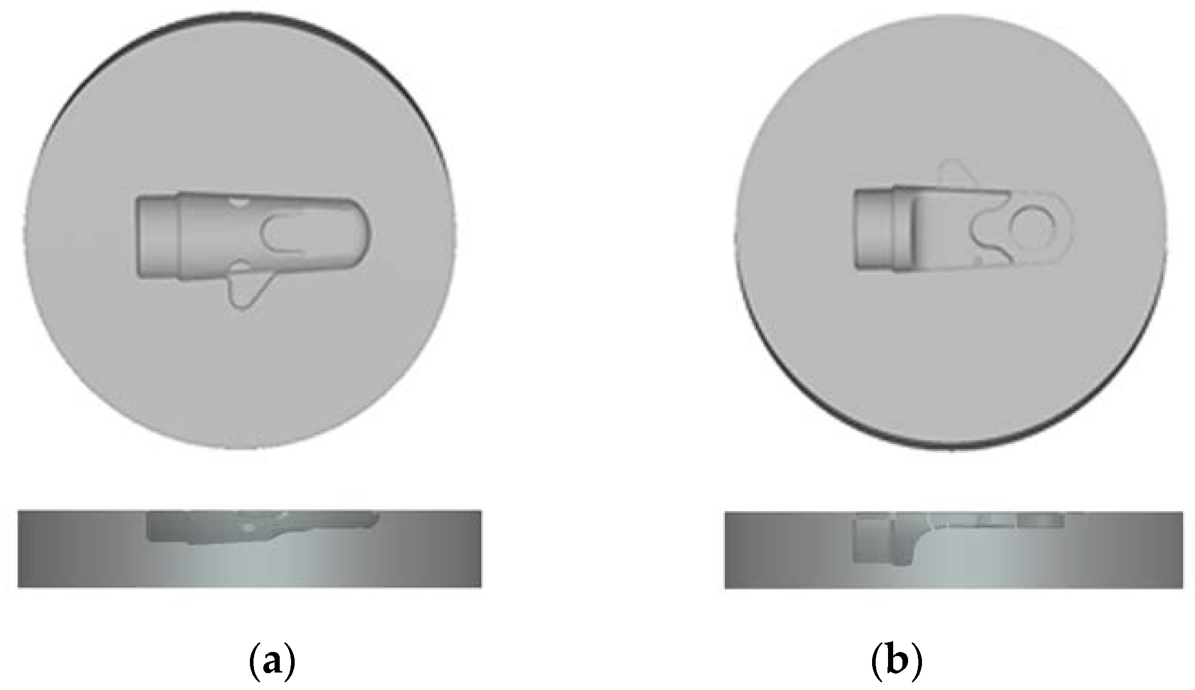
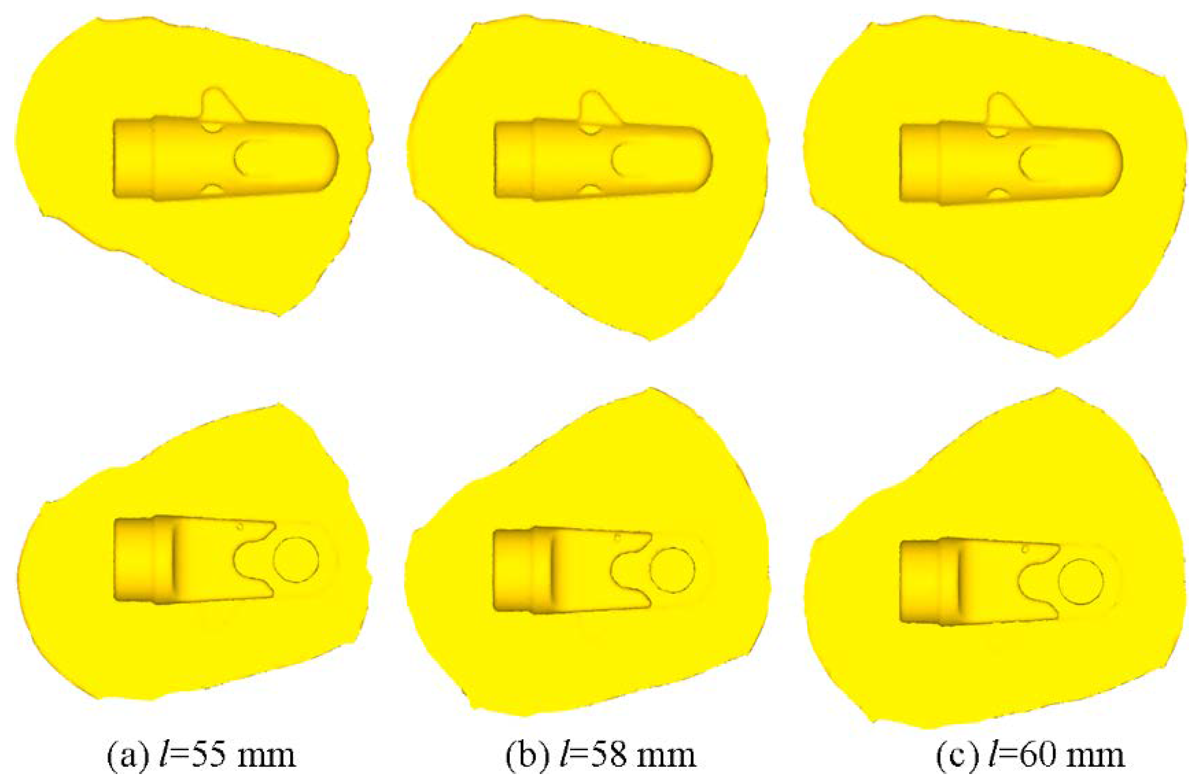
3.1.1. Forming Shape

Figure 8 shows the forming shape of the top and bottom part of the AA6063 aluminum alloy component during cold orbital forming scheme as the blank dimensions are Φ30 mm × 55 mm, Φ30 mm × 58 mm, and Φ30 mm × 60 mm, respectively. In Figure 8, the shapes of the component and some subtle structures are visible, such as the side branch, the boss, and two grooves, which can all be well-formed for the three kinds of blanks with different length. Further, the smaller the blank length, the smaller the flash. When the length of the blank is 55 mm, the formed component has the minimum flash size.
To understand the shaping procedure and forming characteristics of the AA6063 aluminum alloy component with complex shape during cold orbital forming, the component with the length of 58 mm will next be used as an example to analyze in detail.
Figure 9 and Figure 10 show the forming shape evolution of the top and bottom part of the AA6063 aluminum alloy component with length of 58 mm under the different forming time during cold orbital forming scheme, respectively. In Figure 9 and Figure 10, the side branch, the boss, and two grooves are gradually formed, and the side branch is finally formed as the flash expands around the component, as shown in Figure 9c–f and Figure 10c–f, but oversize flash is produced at the end of the shaping, as shown in Figure 9f and Figure 10f.

3.1.2. Distribution of the Effective Strain

Figure 11 shows the distribution of effective strain in the top and bottom part of the AA6063 aluminum alloy component during cold orbital forming scheme as the blank dimensions are Φ30 mm × 55 mm, Φ30 mm × 58 mm, and Φ30 mm × 60 mm, respectively. In Figure 11, the distribution features of the component with different blank length are almost same. When the forming finished, the effective strain was bigger at the boss and the flash, while the effective strain was smaller in the other zone.

3.1.3. Distribution of the Velocity Field

Figure 12 gives the distribution of the velocity field with the forming time as the blank length of 58 mm during cold orbital forming. In Figure 12a,b, the material flows like a vortex around the central axis in the early part of the orbital forming stage. With the increase in forming time, the metal on the right side of the blank was forced into the boss cavity rapidly and diagonally downward, and the boss was gradually filled from the right to the left; moreover, the redundant metal of the right flows rapidly into the flash gutter, as shown in Figure 12c,d. At the end of the filling forming stage, the metal on the left side of the boss flows obliquely upward to fill out the cavity, and the metal above the boss flows vertically downward into the boss cavity at the same time. The redundant metal on the left flows rapidly into the flash gutter, as seen in Figure 12e. When the forming finished, the boss filled again and the metal velocity in the boss cavity tended to zero after shaping of 1 s. The shape of the forging meets the design requirements, as seen in Figure 12f.

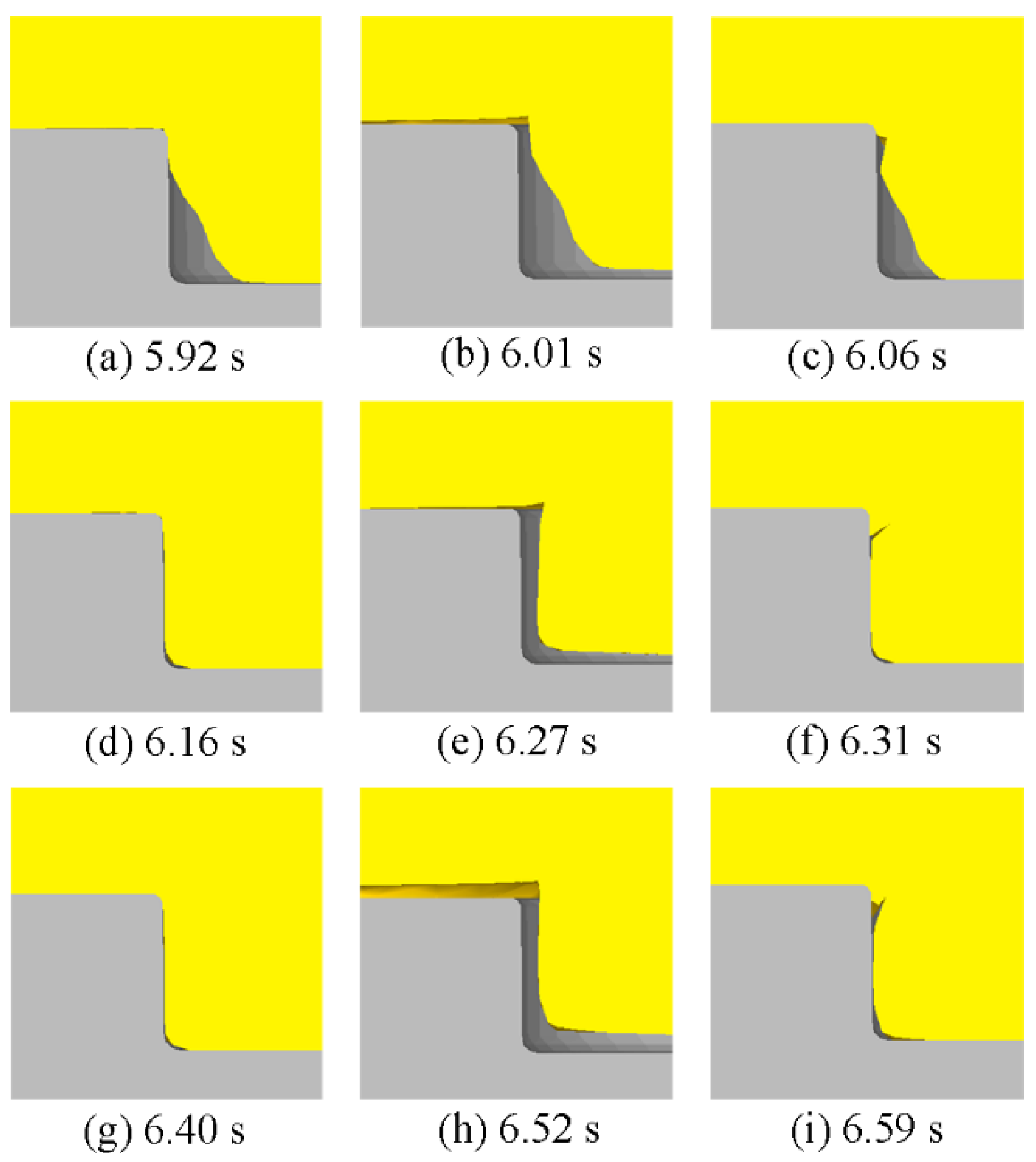
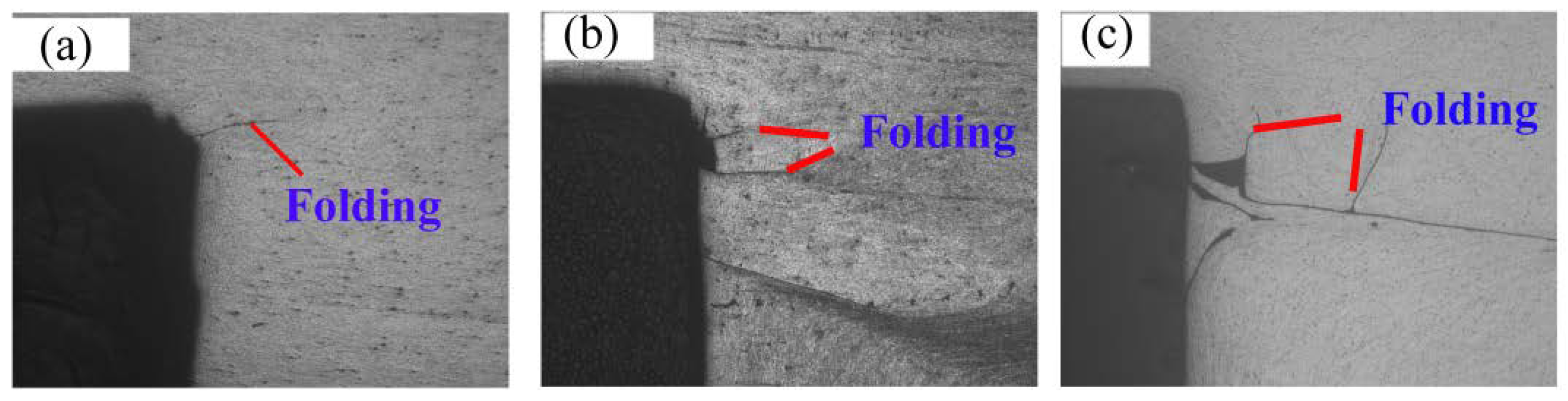
3.1.4. Folding Defect Analysis

Folding is a common phenomenon that comes up in the forging, especially in the forging process of complex-shape aluminum, which can lead to source fatigue and affect the service performance of the component [29]. The material flow velocity of the boss is complex according to the analysis of flow velocity above, which may cause folding phenomena. So, taking the component with the length of 58 mm as an example, the boss was sectioned along its central axial section and the forming procedure was analyzed in detail, as shown in Figure 13.
Figure 13 illustrates the formation of the folding defect when the blank length is 58 mm. In the late forming stage, when the rocking punch is pressed on the left half of the forging, the metal flows into the right of the forging horizontally, which resulted in underfilling phenomena of the boss filled in advance and forming a gap because the metal at the root of the boss is pressed into the right of the forging, as shown in Figure 13a,b. When the rocking punch revolves to the right half of the forging, the metal above the gap flows downward under pressure, and the metal on the right side of the gap flows back to the left (as shown in Figure 12d), thus the gap is filled again and a folding defect is formed, as shown in Figure 13c. During the subsequent forming process, the folding defect is repeatedly generated at the root of the boss during the same forming mechanism. The fold occurs again at the root of the boss when the rocking punch revolves every circle (0.25 s), as shown in Figure 13d–i. Finally, the folding defect forms many times. In summary, due to the severe flowback phenomena during the filling of the boss, the folding defect appears at the inside of the flowback, namely, the left root of the boss.

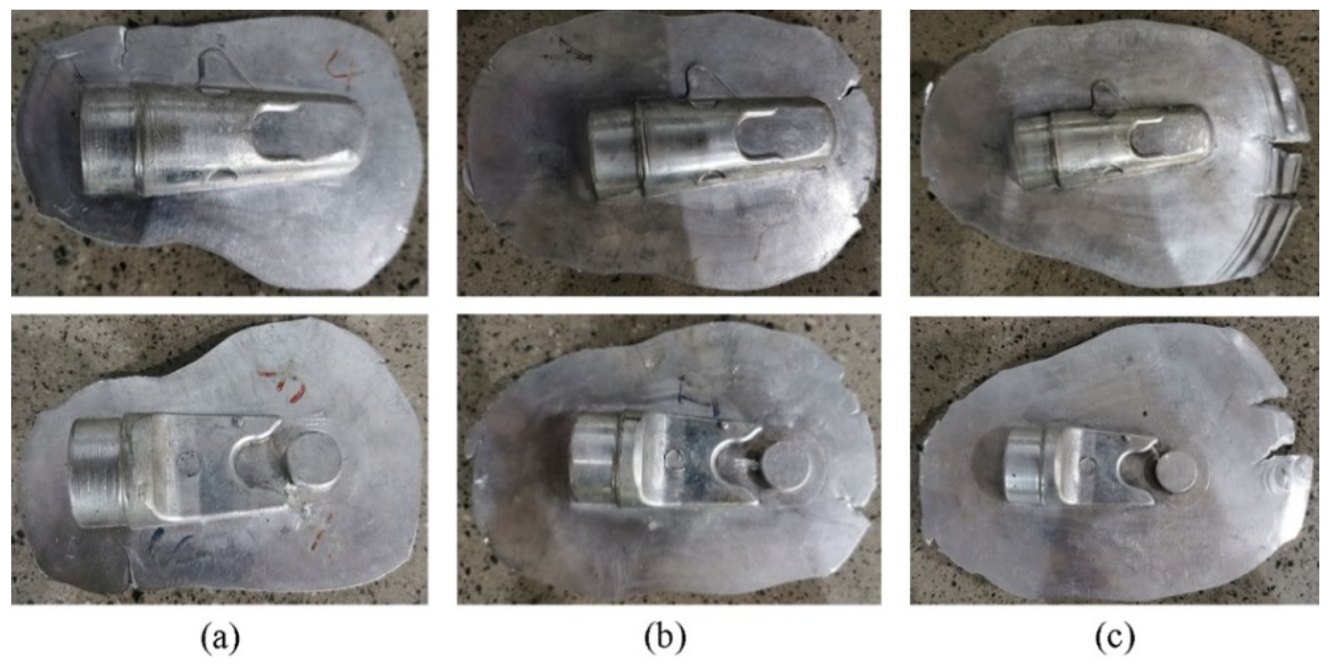
3.2. Experimental Results Analysis

Figure 14 displays the formed AA6063 aluminum alloy component with different blank lengths. In Figure 14, the forming shapes of the component with different blank lengths are almost the same, and all the subtle structures are fully filled at the end of the formation. Besides, the formed forgings have a big flash, and the smaller the blank length, the smaller the flash. The experimental forging shapes are the same as those shown in the FE simulation results in Figure 8.
Moreover, the boss was sectioned along its central axial section and a metallographic sample was prepared, then the metal flow line was observed by Zesis Axio Scope optical microscopy. Figure 15 shows the enlarged graph of the boss of the sample under different bar blank lengths. In Figure 15, a few folding defects exist at the root of the boss, the phenomena may be caused by the different velocities of filling cavities, and the experimental results are the same as FE simulation results.

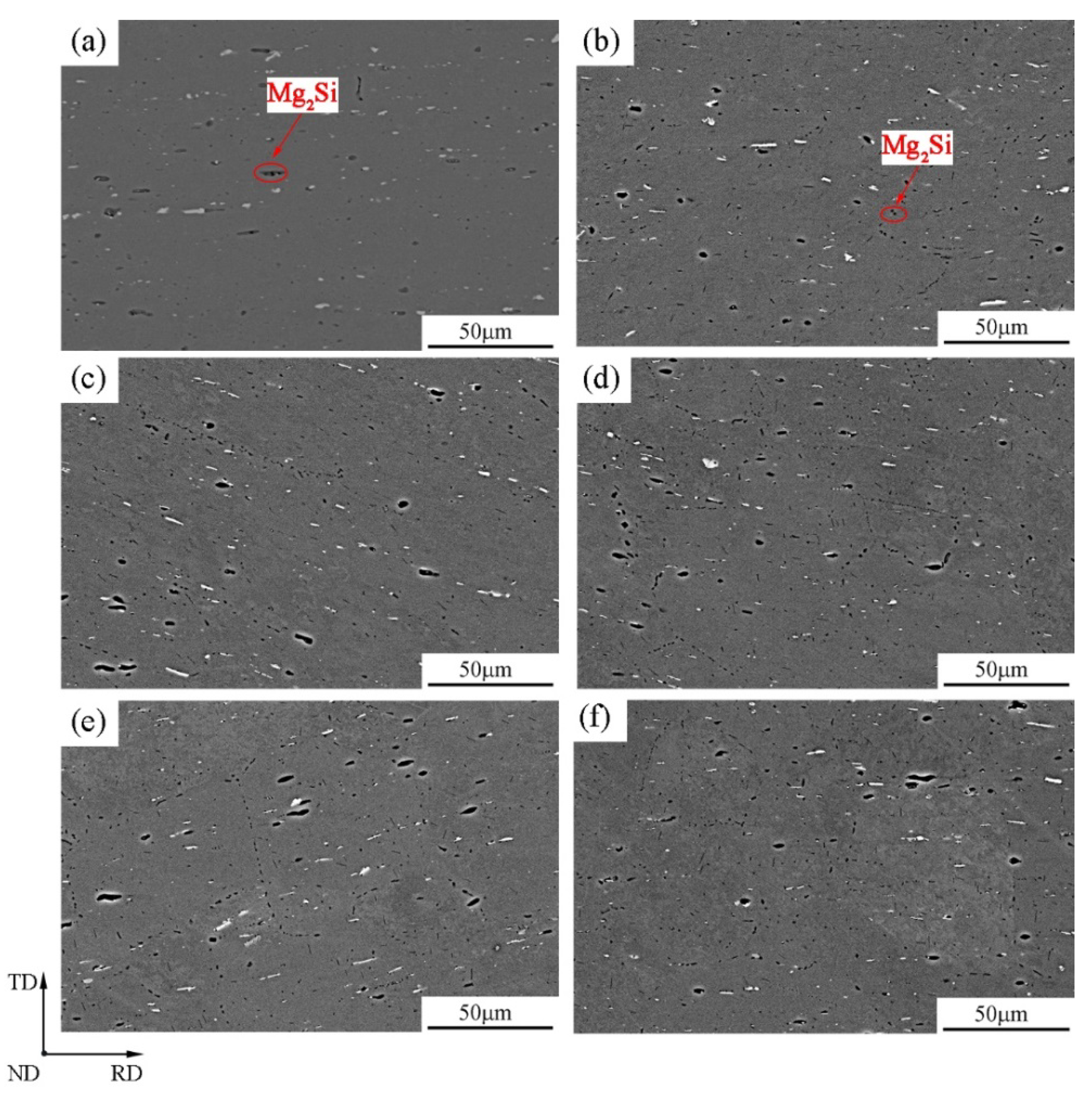
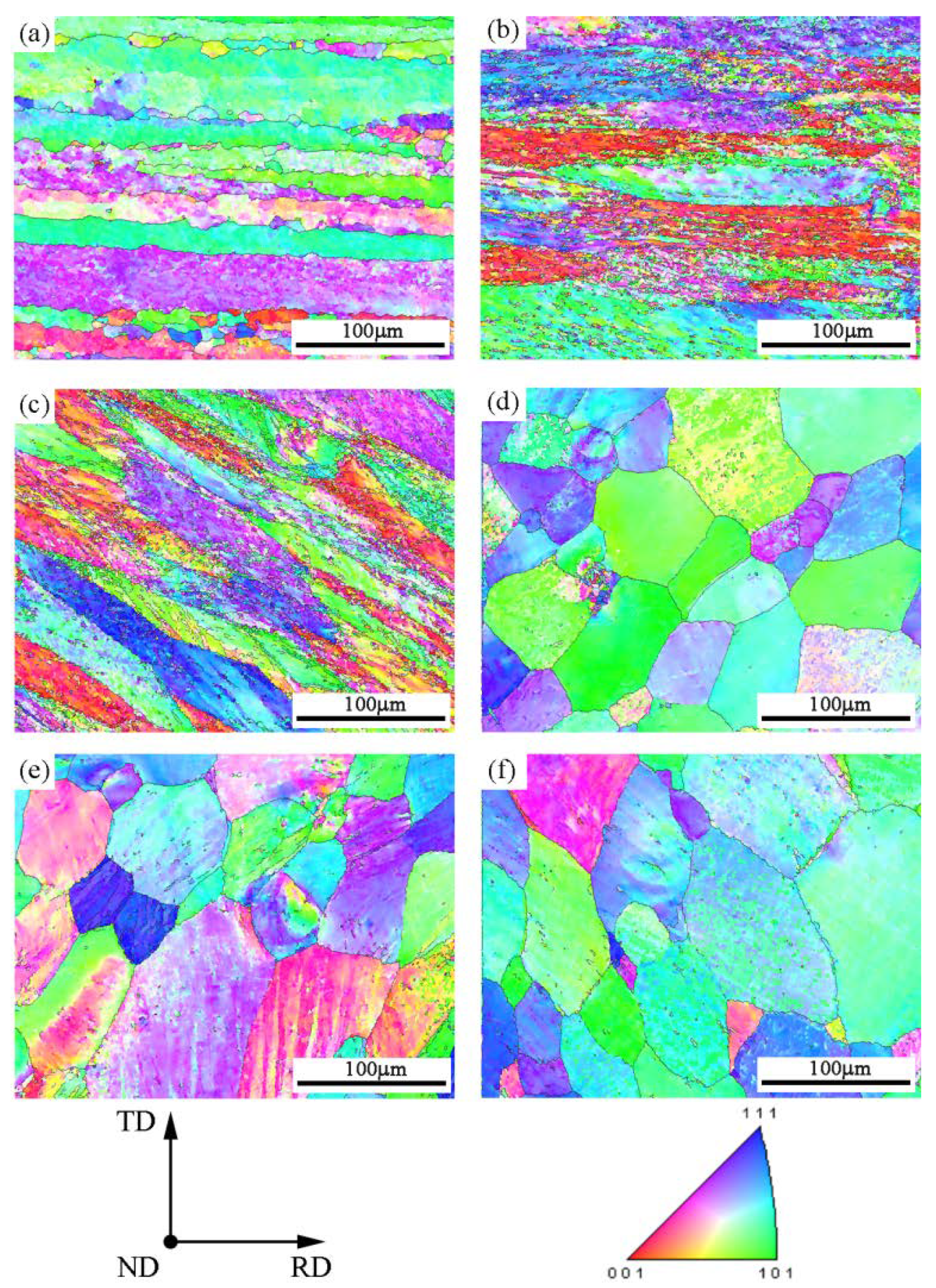
3.3. Microstructure Analysis

According to the above analysis, the material flow velocity is complex in the boss zone; thus, the sample was cut along the longitudinal direction cross section of the boss from the product with blank length of 58 mm processed by cold orbital forming, and the metallographic sample was prepared to study the microstructural characteristics in different position of the boss zone in detail, as shown in Figure 16a. The microstructure observation positions were illustrated in Figure 16b, which was on RD × TD plane; position A is the middle zone in the right part of the formed component; position B is the junction between the middle zone in the right part of the formed component and boss; position D, C, and E are the boss regions with complex flow velocity, respectively.
Figure 17 shows the SEM micrographs of the AA6063 alloy in the blank before forming and in different observation position of the boss after forming, which revealed the precipitates’ characteristics. As shown in Figure 17a, a lot of rod and particle like black precipitates can be observed in the initial blank; these precipitates should be Mg2Si strengthening phase, as referenced in previous studies [30,31]. The distribution of these phases is heterogeneous in the matrix. After the blank deformed, the shape of these rod-like Mg2Si strengthening phase in position A transformed into particles, and they are distributed the matrix in a homogeneous dispersion state, as shown in Figure 17b. The precipitated phases in positions B and D have obvious directivity, pointed to plus 30° and minus 30° along RD, respectively. Parts of the particle shape were elongated into short rod shapes, as seen in Figure 17c,e, while the inclined angle to the RD of the precipitated phases weaken in position C, as shown in Figure 17d. This is caused by the change of metal flow direction at the three positions B, C, and D inside the boss. In Figure 17f, distribution direction of the precipitated phases in position E is almost aligned with RD, which implies position E was subjected to a small deformation. These results agreed well with FE simulation results from Figure 12.
Figure 18 shows the orientation maps (OMs) of the AA6063 alloy in the blank before forming and in the different observation positions of the boss after forming that were obtained by EBSD analysis. In the initial blank in Figure 18a, the microstructure shows ribbon-like fiber morphology in RD × TD plane, and the direction of their long axes is aligned with RD; also, the crystal orientation discrepancy is large. After cold orbital forming, the grains are elongated and are tilted from RD, as shown in Figure 18b–f. In position A in Figure 18b, the crystal orientation discrepancy becomes small compared with that of the initial blank, and the tilted angle is also smaller than that of the other position. In addition, the grains in positions B and D are elongated much more, which implies metal deformed more severely in these zones.

4. Conclusions

In this paper, deformation characteristics and microstructures were studied by FE simulation, processing experiments, and SEM and EBSD examination during cold orbital forming of AA6063 aluminum alloy component with complex shape. It can be concluded that:
(1) It is feasible to manufacture the AA6063 aluminum alloy component with complex shape using cold orbital forming processing. The shape of some subtle structures such as the boss and side branch can be formed well. The distribution features of the effective strain of the component with different blank lengths are almost the same, and the effective strain is bigger at the boss and the flash as the forming finished.
(2) The material flow is complex, especially in the boss, because the contact position between the rocking punch and the blank is changed with forming time under forming. The folding defect was observed at the root of the boss by FE simulation and experimental test. As such, future research should investigate optimizing the form processing and modifying the blank.
(3) After the blank deformed by cold orbital forming, the distributions of Mg2Si strengthening precipitates are more homogeneous in the matrix, and their shape changed from initially rod-like to particles in position A and short rod in the boss zone. Besides, these precipitated phases in the boss zone show obvious directivity due to the change of metal flow direction inside the boss.
(4) After cold orbital forming, the grains are elongated and the extent is different at different positions of boss zone. The crystal orientation discrepancy is smaller in the component main body and bigger in the boss zone. Besides, the elongated grains are tilted from RD.

Author Contributions

Conceptualization and methodology, W.F., C.J. and W.Z.; software and experimental validation, C.J.; investigation, W.F., C.J. and W.Z.; data curation, W.F., C.J.; writing—original draft preparation, W.F., C.J.; writing—review and editing, W.F., C.J., J.D. and W.Z.; supervision, W.F.; funding acquisition, J.D. and W.Z. All authors read and agreed to the published version of the manuscript.

Funding

This research was supported by 111 Project (Grant No. B17034), Innovative Research Team Development Program of Ministry of Education of China (Grant No. IRT13087), and National Natural Science Foundation of China (Grant No. 51805391).

Institutional Review Board Statement

Not applicable.

Informed Consent Statement

Not applicable.

Data Availability Statement

Data is contained within the article.

Acknowledgments

The authors gratefully acknowledge the financial support of 111 Project (Grant No. B17034), Innovative Research Team Development Program of Ministry of Education of China (Grant No. IRT13087), and National Natural Science Foundation of China (Grant No. 51805391).

Conflicts of Interest

The authors declare no conflict of interest.

References

  1. Han, X.H.; Hua, L. Comparison between cold rotary forging and conventional forging. J. Mech. Sci. Technol. 2009, 23, 2668–2678. [Google Scholar] [CrossRef]
  2. Plettke, R.; Opel, S. Investigations on orbital forming of sheet metals to manufacture tailored blanks with a defined sheet thickness variation. Adv. Mater. Res. 2013, 769, 157–164. [Google Scholar] [CrossRef]
  3. Standring, P.M. Characteristics of rotary forging as an advanced manufacturing tool. Proc. Inst. Mech. Eng. Part B. 2001, 215, 935–945. [Google Scholar] [CrossRef]
  4. Gu, Z.Q.; Chen, M.Z.; Wang, C.Y.; Zhuang, W.H. Static and Dynamic Analysis of a 6300 KN Cold Orbital Forging Machine. Processes 2021, 9, 7. [Google Scholar] [CrossRef]
  5. Feng, W.C.; Yao, W.G.; Jiang, P. Influence of eccentricity on movements of orbital head with double eccentric structure in orbital forging. Procedia Eng. 2014, 81, 2348–2354. [Google Scholar] [CrossRef] [Green Version]
  6. Loyda, A.; Reyes, L.A.; Hernández-Muñoz, G.M.; García-Castillo, F.A.; Zambrano-Robledo, P. Influence of the incremental deformation during rotary forging on the microstructure behaviour of a nickel-based superalloy. Int. J. Adv. Manuf. Technol. 2018, 97, 2383–2396. [Google Scholar] [CrossRef]
  7. Hetzel, A.; Merklein, M.; Lechner, M. Enhancement of the forming limits for orbital formed tailored blanks by local short-term heat treatment. Procedia Manuf. 2020, 47, 1197–1202. [Google Scholar] [CrossRef]
  8. Grosman, F.; Madej, Ł.; Ziółkiewicz, S.; Nowak, J. Experimental and numerical investigation on development of new incremental forming process. J. Mater. Process. Technol. 2012, 212, 2200–2209. [Google Scholar] [CrossRef]
  9. Samolyk, G. Investigation of the cold orbital forging process of an AlMgSi alloy bevel gear. J. Mater. Process. Technol. 2013, 213, 1692–1702. [Google Scholar] [CrossRef]
  10. Sheu, J.J.; Yu, C.H. The die failure prediction and prevention of the orbital forging process. J. Mater. Process. Technol. 2008, 201, 9–13. [Google Scholar] [CrossRef]
  11. Qin, X.P. Modelling and simulation of contact force in cold rotary forging. J. Cent. South Univ. 2014, 21, 35–42. [Google Scholar] [CrossRef]
  12. Zhuang, W.H.; Dong, L.Y. Effect of key factors on cold orbital forging of a spur bevel gear. J. Cent. South Univ. 2016, 23, 77–85. [Google Scholar] [CrossRef]
  13. Jiang, S. Microstructure and texture of Ti-6Al-4V alloy deformed by rotary forging at elevated temperatures. Int. J. Mater. Res. 2020, 10, 807–813. [Google Scholar] [CrossRef]
  14. Han, X.; Hua, L. 3D FE modelling of contact pressure response in cold rotary forging. Tribol. Int. 2013, 57, 115–123. [Google Scholar] [CrossRef]
  15. Han, X.; Hua, L.; Zhuang, W.; Zhang, X. Process design and control in cold rotary forging of non-rotary gear parts. J. Mater. Process. Technol. 2014, 214, 2402–2416. [Google Scholar] [CrossRef]
  16. Han, X.; Hu, Y.; Hua, L. A novel cold rotary forging method of producing multiple racks using one set of punch. J. Manuf. Sci. Eng. 2018, 140, 081006. [Google Scholar] [CrossRef]
  17. Han, X.; Hu, Y.; Hua, L. Cold orbital forging of gear rack. Int. J. Mech. Sci. 2016, 117, 227–242. [Google Scholar] [CrossRef]
  18. Han, X.; Zhang, X.; Hua, L. Calculation method for rocking die motion track in cold orbital forging. J. Manuf. Sci. Eng. 2015, 138, 014501. [Google Scholar] [CrossRef]
  19. Han, X.; Jin, Q.; Hua, L. Research on cold orbital forming of complex sheet metal of aluminum alloy. J. Manuf. Sci. Eng. 2017, 139, 1–9. [Google Scholar] [CrossRef]
  20. Milutinović, M.; Baloš, S.; Plančak, M.; Movrin, D. Comparison of some mechanical properties and micro-topography of a.component with non-axisymmetric geometry manufactured by cold orbital and hot forging. J. Mater. Process. Technol. 2017, 249, 179–192. [Google Scholar] [CrossRef]
  21. Cho, H.J.; Koo, J.S. Orbital forming simulation of automotive hub bearing using the explicit finite element method. Int. J. Mod. Phys. B 2008, 22, 1626–1633. [Google Scholar] [CrossRef]
  22. Xiong, W.; Wang, Y.; Li, X.P.; Mei, S.; Tian, Z.X. Study on the forming process and deformation behavior of inner ring in the wheel hub bearing based on riveting assembly. J. Mater. 2019, 12, 3785. [Google Scholar] [CrossRef] [PubMed] [Green Version]
  23. Di Bella, G.; Borsellino, C.; Calabrese, L.; Proverbio, E. Durability of orbital riveted steel/aluminium joints in salt spray environment. J. Manuf. Process. 2018, 35, 254–260. [Google Scholar] [CrossRef]
  24. Presz, W. Ultrasonic orbital microforming—A new possibility in the forming of microparts. Metals 2018, 8, 889. [Google Scholar] [CrossRef] [Green Version]
  25. Presz, W. Material flow in ultrasonic orbital microforming. Metals 2019, 9, 475. [Google Scholar] [CrossRef] [Green Version]
  26. Xin, X.; Gabriela, V.; Pereira, A.B.; Pan, J.Y.; Liao, J. Assessment of Metal Flow Balance in Multi-Output Porthole Hot Extrusion of AA6060 Thin-Walled Profile. Metals 2018, 8, 462. [Google Scholar] [CrossRef] [Green Version]
  27. Chu, G.; Sun, L.; Wang, G.; Fan, Z.G.; Li, H. Axial hydro-forging sequence for variable-diameter tube of 6063 aluminum alloy. J. Mater. Process. Technol. 2019, 272, 87–99. [Google Scholar] [CrossRef]
  28. Feng, X.Y.; Hu, L.X.; Sun, Y.; Liu, Z.Y. Numerical simulation for isothermal forging of cup-shaped component of 6A02 Aluminum alloy. Procedia Manuf. 2019, 37, 478–485. [Google Scholar] [CrossRef]
  29. Shan, D.B.; Zhang, Y.Q.; Wang, Y.; Xu, F.C.; Xu, W.C.; Lv, Y. Defect analysis of complex-shape aluminum alloy forging. Trans. Nonferrous Met. Soc. China 2006, 16, 1574–1579. [Google Scholar]
  30. Chakrabarti, D.J.; Laughlin, D.E. Phase relations and precipitation in Al-Mg-Si alloys with Cu additions. Prog. Mater. Sci. 2004, 49, 389–410. [Google Scholar] [CrossRef]
  31. Zupanič, F.; Steinacher, M.; Žist, S.; Bončina, T. Microstructure and Properties of a Novel Al-Mg-Si Alloy AA 6086. Metals 2021, 11, 368. [Google Scholar] [CrossRef]
Figure 1. The AA6063 aluminum alloy component with complex shape: (a) bottom part, and (b) top part.
Metals 11 00808 g001
Figure 2. 3D solid model of forging for aluminum alloy component with complex shape: (a) top part, (b) bottom part, and (c) main dimensions.
Metals 11 00808 g002
Figure 3. Schematic diagram of one-step cold orbital forming aluminum alloy base: (a) initial stage; (b) forming stage; (c) finished stage; (d) shaping stage.
Metals 11 00808 g003
Figure 4. 3D solid models of non-axisymmetric punches in cold orbital forming the aluminum alloy component: (a) rocking punch; (b) lower die.
Metals 11 00808 g004
Figure 5. 3D FE models for cold orbital forming of aluminum alloy component with complex shape.
Metals 11 00808 g005
Figure 6. Experimental tools for cold orbital forming of the aluminum alloy component with complex shape: (a) Rocking punch, (b) Lower die.
Metals 11 00808 g006
Figure 7. Experimental set up for cold orbital forming of AA6063 component.
Metals 11 00808 g007
Figure 8. Forming shape of top and bottom part of component under different blanks length: (a) l = 55 mm, (b) l = 58 mm, and (c) l = 60 mm.
Metals 11 00808 g008
Figure 9. Forming shape evolution of top part of component with length of 58 mm under different forming time during cold orbital forming: (a) t = 0 s; (b) t = 2.58 s; (c) t = 5.09 s; (d) t = 6.06 s; (e) t = 6.41 s; (f) t = 7.41 s.
Metals 11 00808 g009
Figure 10. Forming shape evolution of bottom part of component with length of 58 mm under different forming time during cold orbital forming: (a) t = 0 s; (b) t = 2.58 s; (c) t = 5.09 s; (d) t = 6.06 s; (e) t = 6.41 s; (f) t = 7.41 s.
Metals 11 00808 g010
Figure 11. Distributions of effective strain of top and bottom part of component under different blank lengths: (a) l = 55 mm, (b) l = 58 mm, and (c) l = 60 mm.
Metals 11 00808 g011
Figure 12. Distribution of velocity field with forming time as blank length of 58 mm during cold orbital forming: (a) t = 0 s; (b) t = 2.58 s; (c) t = 5.09 s; (d) t = 6.06 s; (e) t = 6.41 s; (f) t = 7.41 s.
Metals 11 00808 g012
Figure 13. Formation of fold defect at root of boss: (a) t = 5.92 s, (b) t = 6.01 s, (c) t = 6.06 s, (d) t = 6.16 s, (e) t = 6.27 s, (f) t = 6.31 s, (g) t = 6.40 s, (h) t = 6.52 s, and (i) t = 6.59 s.
Metals 11 00808 g013
Figure 14. Formed aluminum components when lengths of bank are: (a) l = 55 mm, (b) l = 58 mm, and (c) l = 60 mm.
Metals 11 00808 g014
Figure 15. Enlarged graph of root of boss (Magnified 50×) when lengths of bank are: (a) l = 55 mm, (b) l = 58 mm, and (c) l = 60 mm.
Metals 11 00808 g015
Figure 16. Samples in cross section of boss at blank length of 60 mm and observation position: (a) boss cross section sample and (b) sample observation positions.
Metals 11 00808 g016
Figure 17. SEM micrographs of precipitate for AA6063 alloy samples before forming and in different observation positions of boss section after forming: (a) initial blank, (b) position A, (c) position B, (d) position C, (e) position D, and (f) position E.
Metals 11 00808 g017
Figure 18. Orientation maps of AA6063 alloy samples before forming and in different observation position of boss section after forming: (a) initial blank, (b) position A, (c) position B, (d) position C, (e) position D, and (f) position E.
Metals 11 00808 g018
Table 1. The simulation parameters for one-step cold orbital forming base.
ParametersValues
Diameter of blank (mm)30
Length of blank (mm)55, 58, 60
Tilted angle of rocking punch (deg)1.5
Rotational speed of rocking punch (rad/s)25.12
Feed rate of the lower die (mm/s)4
Friction coefficient between punches and blank0.2
Publisher’s Note: MDPI stays neutral with regard to jurisdictional claims in published maps and institutional affiliations.

