Abstract
This study deals with microstructural influence on the H permeation behavior of Dual-Phase (DP) and Complex Phase (CP) steels using electrochemical permeation studies. The H diffusion coefficients in DP steels (DP800: 1.65 × 10⁻¹⁰ m2·s−1, DP1000: 1.58 × 10⁻¹⁰ m2·s−1) are half of that found in CP steels (3.07 × 10⁻¹⁰ m2·s−1).The banded microstructure along the specimen thickness and higher C content of the DP led to high H diffusivity of DP steels. The lower total H concentration along with a higher fraction of H was present in the stronger traps in CP steels suggest a better HE resistance of this steel. The H distribution in the specimens was non-uniform, with a higher H concentration speculated near the charging surface.
1. Introduction
Reducing vehicle weight is a crucial challenge for the automobile industry to increase fuel efficiency and reduce vehicular emission without compromising safety. Advanced High Strength Steels (AHSS), which offer superior strength, are therefore are gaining attention as the body in white material (BIW), with its use increasing from 7% in 2010 to 21% in 2017 (and projected to increase up to 40% by 2025) [1]. These materials are also under interest in other fields such as pipeline, where the corrosion performances versus the chemical composition of steels are investigated in various environments to develop predictive models and to prevent further failures [2,3]. In the latter case, bainite growth in the weld part improved corrosion resistance [4]. Metallurgy of the AHSS is a key parameter that must be controlled along the processing route since it controls the mechanical properties and corrosion resistance of engineering structures [5,6,7,8].
The AHSS are also known to be sensitive to hydrogen embrittlement (HE) and continues to pose an essential bottleneck for their utilization [9,10,11,12,13,14,15]. Hydrogen present in steels, even to an extent of less than 1 ppm, diffuses towards triaxially stressed regions, and thereby cause premature failures. Such failure can occur instantaneously or delayed, making failure prediction difficult, increasing liability, and repair costs [16,17,18]. Since H diffusion directly impacts H transport to stressed areas, studying H permeation behavior in steels is essential in understanding the overall embrittlement behavior [19,20,21,22].
Electrochemical permeation study using Devanathan and Stachurski (DS) cell is an effective way to understand H permeation behavior with good sensitivity by continuously recording the diffusive flow of hydrogen with time [19,23,24,25]. H-permeation depends on its solubility, segregation, and trapping tendency of microstructures. For example, at ambient temperature, the lattice diffusion coefficient of H in pure iron is reported to be around 1.3 × 10⁻⁹ to 7.5 × 10⁻⁹ m2·s−1 whereas it is 4.47 × 10⁻¹¹ m2·s−1 and 5.19 × 10⁻¹¹ m2·s−1 for a fully martensitic and a fully bainitic steels respectively [26,27,28,29]. These microstructural features, such as grain interior, phase interfaces, dislocations, grain boundaries, precipitates, etc., can trap H and reduce the diffusion coefficient by up to two to three orders of magnitude, depending on their activation energies (Ea) [26,27,28]. The activation energy of the traps dictates whether, under stressed conditions, they may behave as sources or sinks for diffusible hydrogen, in turn increasing or decreasing HE susceptibility [30,31,32,33]. The traps also exhibit a strong influence on the H solubility, with an equilibrium between the chemical potentials of lattice and the traps [34]. For example, studies show that DP steels have higher retention for H than bainitic ferrite steel of similar strength and have lower threshold values for HE [35]. In martensitic structure, the steels are reported to trap larger quantities of H as its carbon content is increased, thereby increasing H susceptibility of such steels with carbon content [36]. However, tempering reduces hydrogen sensitivity, with HE resistance increasing with increasing tempering temperature [37]. Bainitic steels also offer good resistance to embrittlement due to their homogeneous, refined, and stress-free microstructures. However, other factors such as carbide type and other micro phases also need to be considered as well [38,39,40].
Needless to emphasize, the AHSS being multiphase steels with varying amounts of ferrite, martensite, bainite, or austenite are expected to exhibit a complex interaction with the H, influencing its diffusivity, solubility, and distribution within the material [41,42,43,44] and its interaction with dislocation nucleation [45]. Thus, especially in the AHSS, there is a need to understand the influence of microstructure on the H permeation behavior as the material microstructure plays an important role in the H distribution [46] and the mechanical properties [47,48] and the cracking mechanism [49,50]. Djukic et al. [51] and Xinfeng et al. [52] have demonstrated that reduction of fracture toughness is not only due to HELP (Hydrogen-enhanced localized plasticity) mechanism, as enumerated by Matin et al. [53], but can be a synergistic action of HELP and HEDE (hydrogen induced decohesion) mechanisms. Jemblie et al. [49] applied a coupled mass transport and cohesive zone approach to model hydrogen induced cracking, showing that the lattice and trapped concentrations of hydrogen play a role in the reduction of cohesive strength.
This study investigates the influence of the microstructure of three first-generation the AHSS namely DP 800, DP1000 and CP1000 with respect to the H permeation behavior in them, specifically in terms of the diffusion coefficient, the H concentration in the lattice and the traps, and trapping capabilities of the investigated steels. The lattice diffusion coefficient of H was experimentally determined and compared among the investigated specimens. The influence of the material microstructure on the H solubility, the segregation between the lattice and the trap sites, and its distribution across the material is studied in detail. Finally, the difference in the trapping behavior among the different steels was discussed, and an average Ea was calculated for each material.
2. Experimental
For the present study, TATA Steel (Oosterhout, Netherlands) provided two DP steels having a tensile strength of about 800 MPa (DP800) and 1000 MPa (DP1000) and a CP steel having a tensile strength of about 1000 MPa (CP1000) in the form of 30 cm × 30 cm sheet of different thicknesses. The DP steels had an average thickness of 0.98 mm, while the CP steel had 1.60 mm average thickness. The chemical compositions of these steels are shown in Table 1.

Table 1.
Chemical composition of the steels in wt.% used in hydrogen permeation study (EDS-SEM analysis).
2.1. Sample Preparation for Metallography
For microstructural evaluation, two 15 mm × 20 mm coupons (one along the specimen surface and the other along the cross-section) from each steel were ground up to 4000 SiC emery paper and then polished up to 1 µm diamond paste. Such selection helped to verify the existence of banding behavior along the rolling direction. Subsequently, they were washed twice with acetone and then with ethanol in an ultrasonic bath and air-dried. The polished surfaces were etched with a 2% Nital solution and observed under a Jeol JSM—7800F PRIME (Jeol, Akishima, Japan) Scanning Electron Microscope (SEM).
2.2. Hydrogen Permeation Specimen Preparation
35 mm × 35 mm coupons were ground up to 600 grit SiC, cleaned twice in an ultrasonic bath with acetone and then with ethanol and air-dried. Pd layer was electrodeposited on one surface (to avoid Fe oxidation at the anodic surface) while other surfaces were masked with a conductive Al tape to avoid Pd deposition. The specimen was immersed in a Pd bath (1L solution: 2.5 g PdCl2, 120 g Na3PO4, 27.5 g NH4PO4, 1.7 g C6H5COOH) and a current density of 2.8 mA·cm−2 was applied for 180 s at room temperature, with a Pt mesh as an anode. ChimiePlus (Saint-Paul-de-Varax, France) supplied all chemicals. After Pd deposition, the tape was removed, both specimen surfaces were cleaned with alcohol and air-dried.
2.3. Hydrogen Permeation Cell
A modified Devanathan and Stachurski cell (D.S. cell or permeation cell), consisting of two compartments, namely charging and detection, separated by a test specimen (working electrode, i.e., W.E.), as outlined in the schematic of Figure 1 was used. Each compartment was equipped with an auxiliary electrode (A.E.: graphite at the detection side and a Pt mesh at the charging side) and a saturated Ag/AgCl reference electrode (R.E.). Two independent Gamry Interface 1000 potentiostats, one to electrochemically reduce H+ at the cathodic/charging side and the other to subsequently oxidize H at the detection/anodic side, were used. A fraction of the H+ reduced at the cathode surface of the specimen was absorbed as H into the specimen, diffused across the specimen, and finally oxidized at the anode surface (Pd coated) of the specimen. In this study, the H+ was reduced galvanostatically with varying current densities and the oxidized potentiostatically at +0.2 V w.r.t. RE. The potential represented an overpotential of +250 mV, ensuring complete ionization of H at the detection side as per Hads → H+ + e−. Heated water circulated in the double jacket to maintain a constant temperature of 35 °C at each compartment.
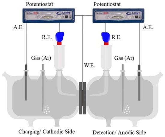
Figure 1.
Schematic of the permeation cell used for this study. H+ is reduced as H at the left compartment and oxidized at the right compartment. The cell was home-made.
2.4. Experimental Procedure
The electrochemical hydrogen permeation experiment was carried out according to the ISO 17081 specifications [10,46,54]. Specimens with an exposed surface area of 7 cm2 were clamped between the two compartments. The anodic compartment was filled with 0.2 M KOH solution (pH = 13; Conductivity = 45.3 mS·cm−1) and anodic potential (+0.2 V w.r.t. R.E.) was applied. Two Ref1000 potentiostat (GAMRY, Warminster, PA, USA) were used to apply and record the current and potentials for each cell. The results were measured using Gamry Framework data acquisition software v6.32. Once the measured current density stabilized below 0.3 µA·cm−2, de-aerated 0.1 M K2SO4, 0.02 M H2SO4 solution (pH = 2.08; Conductivity = 26.5 mS·cm−1) was added slowly at the charging side and the cathodic surface was charged galvanostatically. Ar gas flowed through both the electrolytes throughout the experiment for de-aerating the electrolytes. In the absence of oxygen, H oxidation is the only electrochemical reaction at the anodic surface and provides a direct measure of the H atoms permeating through the specimen.
The galvanostatic charging at the cathodic surface involved the following three steps. As an example, Figure 2a represents the permeation current density as obtained due to the charging schedule at the cathodic surface for CP1000. Similar testing was conducted for other specimens.
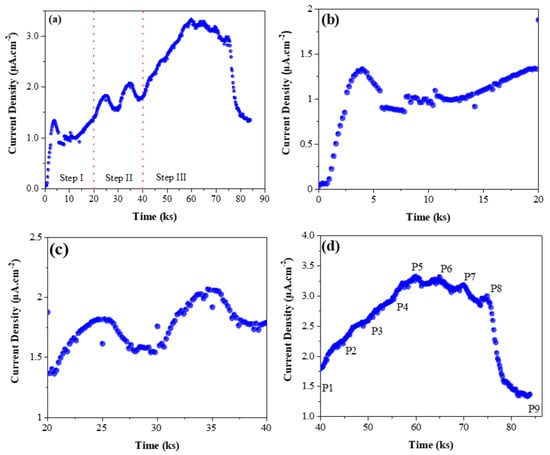
Figure 2.
(a) The complete data of three-step permeation experiment involving pre-charging, successive partial transient, and partial transient loop at different charging current densities for CP1000. Expanded plots of (b) the pre-charging step; (c) the successive partial transient; (d) partial transient loop for CP1000. Each point in the figure (d) corresponds to the applied current density at the charging surface during the test (P1: −10 mA·cm−2; P2: −20 mA·cm−2; P3: −30 mA·cm−2; P4: −40 mA·cm−2; P5: −50 mA·cm−2; P6: −40 mA·cm−2; P7: −30 mA·cm−2; P8: −20 mA·cm−2; P9: −10 mA·cm−2).
- Step I (Cathodic Pre-charging): When the background current density at the detection side was below 0.3 µA·cm−2, a cathodic current density of −10 mA·cm−2 was applied on the charging surface until an observable steady-state current permeation current density occurred (Figure 2b).
- Step II (Subsequent Partial Transient): After step I, the charging current density was raised to −20 mA·cm−2. Once the permeation current density reached a new steady-state, the charging current density was lowered back to −10 mA·cm−2. The applied current density was held for 5000 s for each step. The steps were repeated to verify the permeation curves’ reproducibility (as shown in Figure 2c).
- Step III (Partial Transient Loop): After completing step II, the charging current density was raised from −10 mA·cm−2 to −50 mA·cm−2 and after that lowered to −10 mA·cm−2 (thus creating a loop), with a step size of −10 mA·cm−2 (Figure 2d) and holding time of 5000 s for each step.
The above charging schedule reduces the surface modification influence in the permeating current density occurring at the charging surface, which is one of the key challenges in applying ISO 17081. Additionally, as a cathodic potential is always associated with the charging surface, it minimizes the possibility of corrosion issues, particularly during fall transients [19,27,55,56]. It is reported that surface modifications (dissolution/formation of oxides/hydrides/reaction products) occurring during H charging can significantly facilitate/block hydrogen entry in the material during the test and thus influence the observed permeation behavior [57,58,59,60,61]. According to Turnbull, during the early stages of the test, there will always be a partial surface reaction, and its effect could be minimized by constant charging [54]. A long-term cathodic pre-charging, as carried out in step I, will, therefore, stabilize the specimen surface and minimize the influence of surface modification on the permeation curves [62,63,64].
To verify pre-charging’s effectiveness in reducing surface modification’s influence on permeation current density, the steady-state permeation current density was plotted against the square root of applied cathodic current densities for pre-charged specimens, as shown in Figure 3. The linear relationship between the two parameters validate that the permeation current density is indeed controlled by the impressed cathodic current density and not influenced by surface modifications and is attributed to the activation of cathodic surface facilitating hydrogen absorption [54,65]. Zakroczymski et al. [55] compared this relation in non-pre-charged and pre-charged specimens and observed a sigmoidal curve in case of non-pre-charged specimens, which followed a linear relationship in the case of pre-charged specimens.
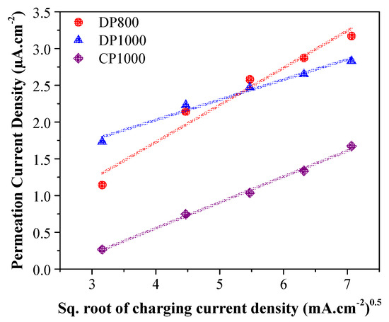
Figure 3.
The variation of steady-state permeation current density with the square root of charging current density. A linear relationship is assumed, suggesting a permeation current controlled by the impressed cathodic current density.
Step II followed step I, where the partial rise and fall transients’ reproducibility were analyzed, as shown in Figure 4a,b. Both curves overlap each other, validating their reproducibility and increasing the reliability of the data obtained from the subsequent steps. Steps I and II are the surface conditioning steps, whereas step III would be used to provide the permeation data. The subsequent partial transients, as shown in Figure 4a,b, were in good agreement with each other. They attributed the good reproducibility to (a) pre-charging, filling up all the irreversible traps leading to the interaction of hydrogen with only the reversible traps and lattice sites after a long pre-charging; (b) the trapping effect from the reversible traps to be similar for both transients; and (c) the surface effects for both the transients to be similar [57,59,66]. The reproducibility of the curves also indicates that there was no permanent damaged caused to the material (also confirmed by observing the specimen under an optical microscope) due to high current density of the cathodic charging, a concern which has been raised by some authors in the past [56,67].
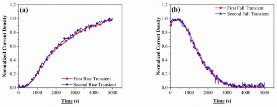
Figure 4.
The normalized curve for two successive (a) rise transients for CP1000 steel when the charging current density was raised from −10 mA/cm2 to −20 mA/cm2 and (b) fall transients for CP1000 steel when the charging current density was lowered from −20 mA/cm2 to −10 mA/cm2.
3. Results
3.1. Microstructure
Figure 5 presents the scanning electron images (SEM) of the three alloys investigated in this study. DP and CP steels cross section images (right column) reveal if there exits any banding behavior along the rolling direction. Such microstructural anisotropy is expected to play a role in the diffusion mechanism of hydrogen (diffusion coefficient, trapping concentration). The phase fractions and the average grain sizes were determined using EBSD and the same are presented along with the mechanical properties in Table 2. Figure 5a,c presents the rolled-surface microstructures of DP800 and DP1000 specimens, respectively that reveal the martensitic islands and ferrite [68]. The high martensite phase fraction in the alloys makes the ferrite discontinuous, an observation similar to the works of Davies et al. [69,70]. Between the two DP steels, DP1000 contains a higher martensite phase fraction than DP800, which is responsible for the higher strength and reduced ductility of DP1000. With a higher martensitic phase fraction and similar size of the martensitic islands in DP1000, the average ferritic grain size in DP800 was significantly larger than DP1000. The higher ferritic grain size can also lower the tensile strength of an alloy.
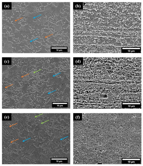
Figure 5.
SEM images of the surfaces of (a) DP800 steel (c) DP1000 steel, (e) CP1000 steel, and cross-sections of (b) DP800 (d) DP1000, and (f) CP1000 steel sheets. The orange, blue and green arrows represent ferrite, martensite, and bainite, respectively.

Table 2.
Summary of the microstructural (phase fraction, average grain size) and mechanical (tensile strength and % Elongation) data of the steels.
Figure 5e presents the as rolled-surface microstructure of the CP1000 specimen, revealing martensite as the predominant phase followed by ferrite and bainite. The CP steel contains significantly higher quantities of bainite than both the DP steels. Further, the average size of the ferrite grains and the martensitic islands found in CP1000 is similar but is smaller than those found in DP steels. The phase fraction of the retained austenite in all the investigated steels was below 0.25%.
Figure 5b,d,f present the cross-sectional images obtained along the rolling direction for all the steel sheets under study. Notably, both the DP800 and DP1000 have banded structures aligned along the rolling direction, whereas CP1000 is free from it.
3.2. Hydrogen Diffusion Coefficient
H diffusion in metals is a critical parameter to understand their sensitivity to HE as it is the diffusible H that migrates to the crack tip, causing embrittlement. The hydrogen diffusion coefficient was calculated by fitting the experimentally obtained partial permeation transient data to Equations (1) and (2), assuming that during H charging, the H concentration at the charging side attains a new value just after the cathodic current density is varied [10,26,30].
where, in is the normalized current density (the initial and final current densities for the partial rise and partial fall transients were 0), D (m2·s−1) is the H diffusion coefficient, L is the specimen thickness (m), and t is the time (s) for each partial transient.
The H diffusion coefficient so-measured corresponds to the apparent diffusion coefficient (Dapp) and not to the lattice diffusion (DL) as traps present in the alloy impede the hydrogen movement [27]. The experimental data fitted to the above equations for the various initial and final charging test conditions for DP800 is presented in Figure 6 for illustration. The goodness of fit of the curves suggests that the hydrogen diffusion is not affected by the slow surface processes [26,27,59,64]. A similar fitting procedure was carried out for the other steels as well.
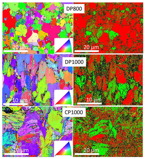
Figure 6.
EBSB analysis of surface microstructure of DP800, DP1000, and CP1000. Inverse pole figures are given in the left column whereas phase indexation is shown in the right column (yellow cementite, green martensite, red ferrite, blue austenite, green martensite).
The diffusion coefficient values obtained in this work for the tested steel specimens are within the range of diffusion coefficients reported in the literature [56,57,71]. The diffusion coefficient values obtained for DP800, DP1000 and CP1000 are in the range: 0.83 to 1.68 × 10⁻¹⁰ m2·s−1; 0.77 to 1.60 × 10⁻¹⁰ m2·s−1; and 1.07 to 3.16 × 10⁻¹⁰ m2·s−1 respectively as presented in Figure 7 and Figure 8.
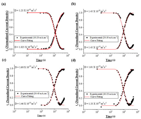
Figure 7.
Partial Permeation Transients for DP800. (a) Rise Transient from −10 to −20 m·cm−2 and Fall transient from −20 to −10 mA·cm−2. (b) Rise Transient from −20 to −30 mA·cm−2 and Fall transient from −30 to −20 mA·cm−2. (c) Rise Transient from −30 to −40 mA·cm−2 and Fall transient from −40 to −30 mA·cm−2. (d) Rise Transient from −40 to −50 mA·cm−2 and Fall transient from −50 to −40 mA·cm−2.
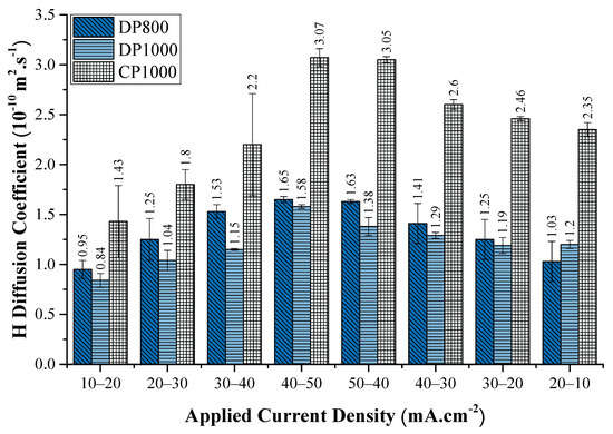
Figure 8.
The evolution of the apparent diffusion coefficient of hydrogen in different steels investigated in this study, with the change in cathodic current density during the rise transient. The values indicate the mean diffusion coefficient value obtained for each transient. Error bars are standard deviation based on two to three experiments.
Figure 8 presents the variation of Dapp with the charging current density for all three steel specimens. The increase in Dapp with increasing charging current density or cathodic overpotential is consistent with the literature [26,56,59,64]. The above increase in Dapp results from the incremental filling of traps and the consequent reduction of the trapping capacity of microstructural features with a step-wise increase in cathodic overpotential/charging current density. Another factor that might contribute to the rising Dapp value with the applied current density is the increase in the H concentration gradient across the membrane facilitating the H diffusion across the membrane.
Similarly, the Dapp value decreases with the subsequent reduction in the charging current density. With the reduction in applied current density, H is released from both the lattice sites and the trap sites, maintaining equilibrium [46]. It results in the increasing influence of trapping sites impeding the H movement and consequently decreasing the Dapp value. With the evident decreasing influence of the traps with increase in charging current density/cathodic overpotential, the lattice H diffusion coefficient (DL) in the investigated steels was calculated from the data obtained at the highest overpotential performed in the study [10,30,59]. The DL values obtained for DP800, DP1000, and CP1000 are 1.65 × 10⁻¹⁰ m2·s−1, 1.58 × 10⁻¹⁰ m2·s−1, and 3.07 × 10⁻¹⁰ m2·s−1 respectively. The so-obtained DL values are assumed to be a close approximation of the actual lattice H diffusion coefficient in the investigated steels. Data shows that CP1000 has the highest DL value, while both the DP steels show nearly the same DL values. As expected, the DL is significantly higher than the corresponding Dapp for all the observed cases. Zakroczymski et al. [27] made similar observations, where the diffusion coefficient of H in non pre-charged pure iron was an order of magnitude smaller than the lattice diffusion coefficient.
3.3. Hydrogen Concentration
The sub-surface and lattice hydrogen concentrations are the other important parameters contributing to HE of steels with only a limited information is available in the published literature. Using the steady-state current density and the calculated diffusion coefficient values, both the total subsurface H concentration (CT) and the lattice H concentration (CL) in mol·m−3, are determined. Under equilibrium conditions, CT and CL are related to the steady-state current density (iss) via the corresponding diffusion coefficients using Equations (1) and (4), respectively [19,72].
where F is the Faraday’s constant.
The difference between the CT and CL corresponds to the H present in the traps (CTrapped). The above three H concentration values are plotted against the charging current density in Figure 9, and the corresponding data is presented in Table 3. In general, all the three H concentration values increase with increase in the applied current density. The data suggest that CT and CTrapped for the steels vary in the order DP1000 > DP800 > CP1000, while a cross-over, from the above trend, occurs for DP800 at higher charging current density with respect to DP1000 for CL, indicating that DP800 has the highest value at higher charging current densities. The subsurface H concentration also has an inverse relationship with the DL. The steel with lower DL has higher sub-surface concentrations (Figure 7 and Figure 8). It is understandable, since the H that enters the steel due to cathodic charging diffuses faster into the steel as it has a high DL value [73].
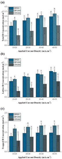
Figure 9.
The evolution of (a) the total hydrogen concentration at the sub-surface of the charging side, (b) the lattice hydrogen concentration at the sub-surface of the charging side, and (c) the trapped hydrogen concentration at the sub-surface of the charging side with change in the cathodic current density. Error bars are standard deviation based on two to three experiments.

Table 3.
The trap density, total amount of hydrogen released, and the activation energy of the specimens obtained from the fall transient of the permeation curve.
Further, it is observed that CTrapped saturates beyond 20 mA·cm−2 because of the finite trap sites. Such a distinct saturation is not noted for CT (Figure 9a). It appears that the increase in the H fugacity with applied current density enables higher solubility of hydrogen in the steel, although at high hydrogen fugacity, hydrogen recombination may be favored. Further, with an increase in the charging current density, the available free sites for H reduction are expected to decrease, due to the increased surface coverage by the adsorbed H atoms, limiting the H adsorption. As shown in Figure 9, when the charging current density is increased from −20 mA·cm−2 to −30 mA·cm−2 for DP800, the increase in total hydrogen concentration is 0.55 mol·m−3, whereas at higher charging current densities, when it is raised from −40 mA·cm−2 to −50 mA·cm−2, the change in hydrogen concentration is only 0.19 mol·m−3.
3.4. Hydrogen Trapping
Reversible H traps also affect steels’ HE tendency, as these traps act as reservoirs for hydrogen atoms and release them into the lattice over time. The experimental permeation falls transient curve is sensitive to the hydrogen in the reversible traps, with the area under the curve representing H desorbed from the lattice and reversible trap sites (CT*). The detrapping kinetics of hydrogen from the reversible traps is calculated by subtracting a decay curve corresponding to DL (Equation (2)) from the experimentally obtained current decay curve [10,27,57,59].
Figure 10 shows the fall transients’ schematic for DP1000 steel at different charging current densities and the corresponding calculated current due to oxidation of lattice H, using DL values. Assuming only one kind of trap site present in the material, and each trap site can hold only one H atom, the reversible trap density is calculated using Equation (6) [57].
where NT is the number of hydrogen trapping sites per unit volume (sites·cm−3), A is the difference in the area under the two curves (s), L is the thickness of the specimen (cm), in is the steady-state current, and 6.24 × 10¹² is the number of hydrogen atoms in 1 µA·s·cm−2.
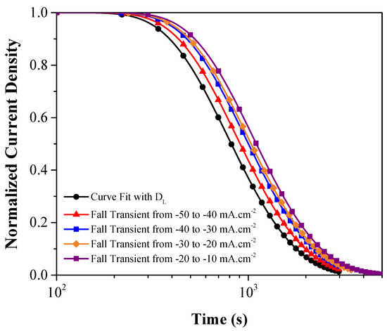
Figure 10.
The schematic normalized current density for the decay transient for each fall transient and the theoretical curve calculated using DL = 1.58 × 10⁻¹⁰ m2·s−1 for DP1000 steel.
The calculated NT summarized in Table 3 indicates that with increasing charging current density, the reversible trap sites of all the three steels decrease. Further, the calculated reversible trap density varies in the order DP800 > DP1000 > CP1000. The trap density emptied during fall transients increases with decreasing charging current densities. For example, in the DP800, lowering charging current density from −50 mA·cm−2 to −40 mA·cm−2 emptied only 12.5% of the total calculated traps, whereas lowering the charging current density from −20 mA·cm−2 to −10 mA·cm−2, 46.2% of the total calculated traps were emptied. All the steels investigated demonstrated similar behavior. In DP steels, the calculated trap density was higher in DP800 than DP1000. It is possibly related to the energy associated with the traps. If the trap strength of DP1000 is stronger than DP800, it is understandable that fewer traps would be emptied with a reduction in charging current density (Table 3).
3.5. Trap Activation Energy
The binding energy of hydrogen with traps play a decisive role in determining the diffusion/trapping of H in the material. Following the works of Oriani [46] and later modified by Dong [74], the activation energy of the traps can be calculated from the obtained permeation data [75] using Equation (2):
where NT is the number of hydrogen trap density (sites·cm−3), NL is the density of interstitial sites in the steel, Ea is the activation energy for the traps, R is the gas constant and T is the absolute temperature.
Based on similar works available in the literature, the interstitial site density (NL) is assumed 7.52 × 10²² sites·cm−3 [20,76]. The average Ea calculated for DP800 is 34.05 kJ·mol−1, 37.61 kJ·mol−1 for DP1000 and 38.94 kJ·mol−1 for CP1000. The activation energy measured from the permeation technique is usually higher than the values obtained by TDS measurements [77]. In TDS, when the thermal energy is applied, all the hydrogen present in the material effuses out. However, in the permeation method, the decrease in the cathodic overpotential may not be sufficient to release all the hydrogen present in the traps. As trap density is inversely proportional to the activation energy, the Ea calculated from permeation tests present a higher value. Though the activation energy measured from the permeation technique may not be accurate; nevertheless, it can provide a reasonable idea about the nature of traps.
4. Discussion
The present study suggests that the lattice H diffusion coefficient in CP steel was higher compared to the DP steels. For CP steel, the bainite promotes hydrogen diffusion [44,78] and in the case of percolate phase, the hydrogen effective diffusivity could be enhanced, as discussed by Fielding et al. [79]. Therefore, H diffusion path (percolate phases, metallugical defects) influences the observed diffusion coefficient values of these steels. As shown in Figure 5b,d,f, DP steels have a banded structure across its cross-section, which is not present in CP steel. The banded structure indicates a longer mean diffusible path for hydrogen in DP steels than in CP steel. In DP steels, the grain boundaries are the preferred diffusion pathway as the matrix is predominantly ferrite [80]. Koyama et al. [81], using the Ag decoration technique, reported that grain boundaries were the preferred diffusion pathways for hydrogen in ferrite. Haq et al. [56] reported that effective hydrogen diffusivity in specimens with banded structure perpendicular to the direction of hydrogen diffusion tends to be an order of magnitude lower than specimens with bands parallel to the direction of hydrogen diffusion. Olden et al. [82] reported that the greater the diffusion path and the higher the tortuosity of hydrogen, the lower the diffusion coefficient of hydrogen is. Zakromyzski discussed that the flux of hydrogen is directed along the layers of fibres of inclusions [27].
Among the three steels investigated, the CT, CL, and the CTrapped (Figure 9) were significantly lower for CP1000 compared to both DP1000 and DP800. Looking at the carbon content in all the steels, as presented in Table 1, the C content in CP steel is relatively less than DP steels. Carbon concentration in steels is known to influence its HE susceptibility and, consequently, the hydrogen concentration in steel and its diffusion coefficient. Noh et al. [83] observed that an increase of C in austenitic stainless steels increases the susceptibility of hydrogen embrittlement [40]. For Hadam et Zakroczymski [64], the lattice solubility of hydrogen in Armco iron is 70 times lower than in high carbon steel, which is in line with the study of Noh et al., when the influence of other elements variations is neglected in the first approach.
In the absence of the knowledge of the charging schedule, an inference could be drawn that the hard phases, particularly martensite in CP1000 steel, is softer as compared to the DP1000. This is due to the higher phase fraction of hard phases in CP steel with lower C concentration as compared to DP1000. Softer martensite contains lesser dislocation density and less stressed ferrite regions around the ferrite/martensite interface [37]. As dislocation density presented in the martensite is considered a reversible trap site, CP1000 has a lesser number of reversible trap sites compared to DP steels, even though CP1000 has a higher grain boundary area due to its refined microstructure. It is consistent with the trap density observed in Table 3, explaining the small quantity of trapped H in CP steels.
However, though the trap density is smaller in CP1000, under similar charging conditions, a higher fraction of H is trapped in CP steels as compared to the DP steels. From Figure 9, if we calculate the fraction of the total absorbed hydrogen present in traps, it is evident that a higher fraction of H is trapped in CP1000, as shown in Figure 11. In CP steels, there is a significant portion of bainite, which is composed of cementite precipitates. These cementite particles are known to be strong hydrogen traps and are the major trapping sites in the bainitic phase [37]. The size and morphology of the carbide particles also play an essential role in determining the permeability of hydrogen. Ramunni et al. [84], observed finer carbides as being more efficient in hydrogen trap sites. The higher trap activation energy of CP steel also supports the present observation (Table 3).
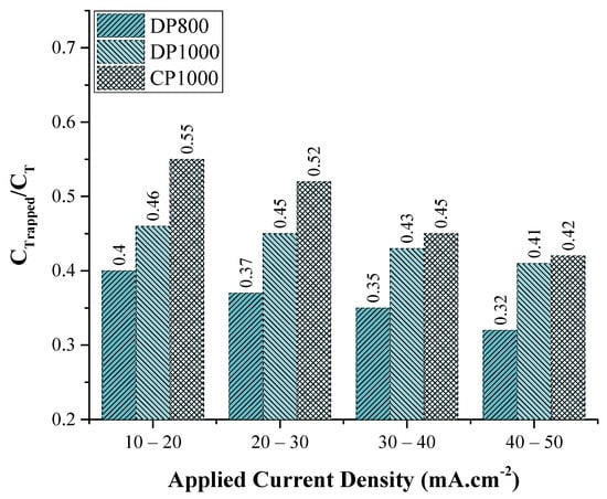
Figure 11.
CTrapped/CT values as calculated from the partial permeation rise transient.
Chun et al. [85] reported that the Ea associated with dislocations and grain boundaries to be around 35 kJ·mol−1. Luppo et al. [86], in their study of low carbon martensitic steel, found that Ea for lath interfaces to be 46 kJ·mol−1. Wong et al. [87] found the energy required to release hydrogen from dislocations to be around 21 kJ·mol−1. Based on these previous results, the hydrogen released from the reversible traps may be present in the grain boundaries, dislocations, and martensite lath interfaces in DP and CP steels along with cementite particles present in CP steels. The low hydrogen uptake, the lower trap density, and the presence of stronger traps in CP steels are expected to render this steel more resistant to HE as compared to the DP steels [16,37,63,76,88,89,90].
Figure 9 suggests that CL is higher for DP1000 at low charging current density, but at higher charging current density, CL is higher for DP800 (Figure 9b). Both DP steels have ferrite and martensite, with higher martensite fraction in DP1000. Martensite, due to its high dislocation density, acts as a hydrogen trap, and resultantly DP1000 has higher trap density than DP800. Thus, the traps in DP800 are quickly get saturated compared to the traps in DP1000, leading to enrichment of hydrogen in DP800 lattice. This observation is particularly interesting in terms of embrittlement phenomenon as Koyama et al. [91] observed that the crack initiation in DP steels occurred through martensite cracking and propagated through the ferrite/martensite interface. The martensite or the martensite/ferrite interface thus can act as strong or weak H trapping sites depending on the activation energy.
Another interesting observation is made by comparing H concentration change at the charging side and discharging side during each fall transient. The change in the hydrogen concentration at the discharge side (CT*) is calculated by measuring the area of the experimental curve. It is observed that for all the steels, the concentration of hydrogen coming out of the discharge side is almost a third of the change in the concentration of the charging side. The ratio between the change in the hydrogen concentration at the discharging side and at the charging side is 0.36 for DP800, 0.33 for DP1000, and 0.30 for CP1000 steels (Table 3). This helps to get an insight into the possible hydrogen distribution within the metal. Hadam et al. [64] suggested that H distribution within the material is uneven along the material cross-section, with most of the H trapped at the sub-surface on the charging side of the specimen. Zakroczymski [64] showed that most of the hydrogen desorbed through the charging side of the specimen. After the permeation current reached the steady state, Zakroczymski interrupted the cathodic charging, and an anodic potential equal to the discharging side was applied to the charging side, which allowed the measurement of desorbed hydrogen from both surfaces. The hydrogen detected from the discharging side accounted for only 12.4% of the total hydrogen released. In the present test conditions, there is the possible release of hydrogen from both sides (charging and discharging). As a result, the total hydrogen desorbed from the discharge side is around one-third of the total change in the hydrogen concentration at the charging side. It must be remembered that in this case, there is no anodic potential applied at the charging side after steady-state, but the only driving force of desorption of hydrogen from the charging side is the lowering of cathodic current density. This interpretation is, however, just speculative and needs further validation as the H concentration profile is extremely difficult to be verified experimentally [92]. However, if true, such observations can provide better insight to interpret the trapping effect of different microstructural structures in the material.
5. Conclusions
Permeation characteristics of DP and CP steels were investigated in the study using the electrochemical hydrogen permeation technique to understand the microstructural influence. The influence of charging surface modification during permeation experiments was successfully mitigated by pre-charging the specimens before the permeation experiment. The salient findings of the work are summarized below:
- DL in CP1000 steel is twice as compared to that of the DP800 and DP1000 steels.
- Higher DL in CP1000 steel is due to the microstructural feature that lowered trap density and enabled easier H diffusion and decreased H concentration at the sub-surface. The relatively lower carbon concentration in CP steels is a possible reason for the low H sub-surface concentration.
- Higher fraction of the trapped hydrogen in CP steel is due to the presence of cementite particles.
- CP steel had the least trap density compared to DP steels but had a higher trap strength.
- CL is higher for DP800 due to easier saturation of traps in DP800 leading of H enrichment in the lattice.
- H concentration effusing from the discharge side is almost a third from that of the charging side, suggesting a non-uniform distribution of H across the cross-section, and higher H concentration near the charging surface.
Author Contributions
Conceptualization, B.N.; methodology, D.M. and N.M.; validation, B.N., D.M., N.M., V.S.R.; investigation, D.M.; writing—original draft preparation, D.M. and N.M.; writing—review and editing, B.N. and V.S.R.; supervision, B.N. and N.M.; project administration, B.N. and V.S.R.; funding acquisition, B.N. All authors have read and agreed to the published version of the manuscript.
Funding
This research received no external funding.
Institutional Review Board Statement
Not applicable.
Informed Consent Statement
Not applicable.
Data Availability Statement
No new data were created or analyzed in this study. Data sharing is not applicable to this article.
Acknowledgments
The authors would like to express their gratitude TATA Steel, Netherlands, for providing the steel specimens for carrying out the experiments.
Conflicts of Interest
The authors declare no conflict of interest.
References
- American Iron and Steel Institute: Automotive. Available online: http://www.Autosteel.Org/Research/Growth-of-Ahss (accessed on 1 October 2020).
- Khalaj, G.; Pouraliakbar, H.; Arab, N.; Nazerfakhari, M. Correlation of Passivation Current Density and Potential by Using Chemical Composition and Corrosion Cell Characteristics in HSLA Steels. Measurement 2015, 75, 5–11. [Google Scholar] [CrossRef]
- Djukic, M.B.; Bakic, G.M.; Zeravcic, V.S.; Sedmak, A.; Rajicic, B. Hydrogen Embrittlement of Industrial Components: Prediction, Prevention, and Models. Corrosion 2016, 72, 943–961. [Google Scholar] [CrossRef]
- Khalaj, G.; Khalaj, M.-J. Investigating the Corrosion of the Heat-Affected Zones (HAZs) of API-X70 Pipeline Steels in Aerated Carbonate Solution by Electrochemical Methods. Int. J. Press. Vessels Pip. 2016, 145, 1–12. [Google Scholar] [CrossRef]
- Nanda, T.; Singh, V.; Singh, G.; Singh, M.; Kumar, B.R. Processing Routes, Resulting Microstructures, and Strain Rate Dependent Deformation Behaviour of Advanced High Strength Steels for Automotive Applications. Arch. Civ. Mech. Eng. 2021, 21, 7. [Google Scholar] [CrossRef]
- Montoya-Rangel, M.; Garza-Montes de Oca, N.; Gaona-Tiburcio, C.; Colás, R.; Cabral-Miramontes, J.; Nieves-Mendoza, D.; Maldonado-Bandala, E.; Chacón-Nava, J.; Almeraya-Calderón, F. Electrochemical Noise Measurements of Advanced High-Strength Steels in Different Solutions. Metals 2020, 10, 1232. [Google Scholar] [CrossRef]
- Wang, L.; Dong, C.; Man, C.; Hu, Y.; Yu, Q.; Li, X. The Effect of Microstructure on Corrosion Behavior of Ultra-High Strength Martensite Steel-A Literature Review. Int. J. Miner. Metall. Mater. 2020. [Google Scholar] [CrossRef]
- Popov, B.N.; Lee, J.-W.; Djukic, M.B. Chapter 7—Hydrogen Permeation and Hydrogen-Induced Cracking. In Handbook of Environmental Degradation of Materials, 3rd ed.; Kutz, M., Ed.; William Andrew Publishing (USA): Burlington, MA, USA, 2018; pp. 133–162. ISBN 978-0-323-52472-8. [Google Scholar]
- Loidl, M.; Kolk, O.; Veith, S.; Göbel, T. Characterization of Hydrogen Embrittlement in Automotive Advanced High Strength Steels. Mater. Werkst. 2011, 42, 1105–1110. [Google Scholar] [CrossRef]
- Fallahmohammadi, E.; Bolzoni, F.; Lazzari, L. Measurement of Lattice and Apparent Diffusion Coefficient of Hydrogen in X65 and F22 Pipeline Steels. Int. J. Hydrogen Energy 2013, 38, 2531–2543. [Google Scholar] [CrossRef]
- Sun, S.; Gu, J.; Chen, N. The Influence of Hydrogen on the Sub-Structure of the Martensite and Ferrite Dual-Phase Steel. Scr. Metall. 1989, 23, 1735–1737. [Google Scholar] [CrossRef]
- Lynch, S. Some Fractographic Contributions to Understanding Fatigue Crack Growth. Int. J. Fatigue 2017, 104, 12–26. [Google Scholar] [CrossRef]
- Lynch, S. Hydrogen Embrittlement Phenomena and Mechanisms. Corros. Rev. 2012, 30. [Google Scholar] [CrossRef]
- Koyama, M.; Akiyama, E.; Tsuzaki, K. Effect of Hydrogen Content on the Embrittlement in a Fe–Mn–C Twinning-Induced Plasticity Steel. Corros. Sci. 2012, 59, 277–281. [Google Scholar] [CrossRef]
- Depover, T.; Vercruysse, F.; Elmahdy, A.; Verleysen, P.; Verbeken, K. Evaluation of the Hydrogen Embrittlement Susceptibility in DP Steel under Static and Dynamic Tensile Conditions. Int. J. Impact Eng. 2019, 123, 118–125. [Google Scholar] [CrossRef]
- Bhadeshia, H.K.D.H. Prevention of Hydrogen Embrittlement in Steels. ISIJ Int. 2016, 56, 24–36. [Google Scholar] [CrossRef]
- Avramovic-Cingara, G.; Ososkov, Y.; Jain, M.K.; Wilkinson, D.S. Effect of Martensite Distribution on Damage Behaviour in DP600 Dual Phase Steels. Mater. Sci. Eng. A 2009, 516, 7–16. [Google Scholar] [CrossRef]
- Hilditch, T.; Lee, S.; Speer, J.; Matlock, D. Response to Hydrogen Charging in High Strength Automotive Sheet Steel Products. SAE Tech. Pap. 2003, 1764, 47–56. [Google Scholar] [CrossRef]
- Addach, H.; Berçot, P.; Rezrazi, M.; Takadoum, J. Study of the Electrochemical Permeation of Hydrogen in Iron. Corros. Sci. 2009, 51, 263–267. [Google Scholar] [CrossRef]
- Zhang, L.; Cao, W.; Lu, K.; Wang, Z.; Xing, Y.; Du, Y.; Lu, M. Effect of the Cathodic Current Density on the Sub-Surface Concentration of Hydrogen in X80 Pipeline Steels under Cathodic Protection. Int. J. Hydrogen Energy 2017, 42, 3389–3398. [Google Scholar] [CrossRef]
- Birnbaum, H.K.; Sofronis, P. Hydrogen-Enhanced Localized Plasticity—A Mechanism for Hydrogen- Related Fracture. Mater. Sci. Eng. A 1994, A176, 191–202. [Google Scholar] [CrossRef]
- Sofronis, P. Viable Mechanisms of Hydrogen Embrittlement—A Review. AIP Conf. Proc. 2006, 837, 64–70. [Google Scholar]
- Plennevaux, C.; Kittel, J.; Frégonèse, M.; Normand, B.; Ropital, F.; Grosjean, F.; Cassagne, T. Contribution of CO2 on Hydrogen Evolution and Hydrogen Permeation in Low Alloy Steels Exposed to H2S Environment. Electrochem. Commun. 2013, 26, 17–20. [Google Scholar] [CrossRef]
- Ma, H.C.; Zagidulin, D.; Goldman, M.; Shoesmith, D.W. Influence of Iron Oxides and Calcareous Deposits on the Hydrogen Permeation Rate in X65 Steel in a Simulated Groundwater. Int. J. Hydrogen Energy 2021, 46, 6669–6679. [Google Scholar] [CrossRef]
- Dey, S.; Sivaprasad, S.; Das, N.; Chattoraj, I. Study of Electrochemical Behavior, Hydrogen Permeation and Diffusion in Pipeline Steel. Mater. Sci. Forum 2021, 1019, 145–156. [Google Scholar] [CrossRef]
- Zakroczymski, T. Electrochemical Determination of Hydrogen in Metals. J. Electroanal. Chem. 1999, 475, 82–88. [Google Scholar] [CrossRef]
- Zakroczymski, T. Adaptation of the Electrochemical Permeation Technique for Studying Entry, Transport and Trapping of Hydrogen in Metals. Electrochim. Acta 2006, 51, 2261–2266. [Google Scholar] [CrossRef]
- Thomas, R.L.S.; Li, D.; Gangloff, R.P.; Scully, J.R. Trap-Governed Hydrogen Diffusivity and Uptake Capacity in Ultrahigh-Strength AERMET 100 Steel. Metall. Mater. Trans. A 2002, 33, 1991–2004. [Google Scholar] [CrossRef]
- Parvathavarthini, N.; Saroja, S.; Dayal, R.K.; Khatak, H.S. Studies on Hydrogen Permeability of 2.25% Cr–1% Mo Ferritic Steel: Correlation with Microstructure. J. Nucl. Mater. 2001, 288, 187–196. [Google Scholar] [CrossRef]
- Lan, L.; Kong, X.; Hu, Z.; Qiu, C.; Zhao, D.; Du, L. Hydrogen Permeation Behavior in Relation to Microstructural Evolution of Low Carbon Bainitic Steel Weldments. Corros. Sci. 2016, 112, 180–193. [Google Scholar] [CrossRef]
- Lee, J.-Y.; Lee, S.M. Hydrogen Trapping Phenomena in Metals with BCC and FCC Crystals Structures by the Desorption Thermal Analysis Technique. Surf. Coat. Technol. 1986, 28, 301–314. [Google Scholar] [CrossRef]
- Lee, S.-M.; Lee, J.-Y. The Trapping and Transport Phenomena of Hydrogen in Nickel. Metall. Trans. A 1986, 17, 181–187. [Google Scholar] [CrossRef]
- Smanio, V.; Fregonese, M.; Kittel, J.; Cassagne, T.; Ropital, F.; Normand, B. Wet Hydrogen Sulfide Cracking of Steel Monitoring by Acoustic Emission: Discrimination of AE Sources. J. Mater. Sci. 2010, 45, 5534–5542. [Google Scholar] [CrossRef]
- Krom, A.H.M.; Bakker, A. Hydrogen Trapping Models in Steel. Metall. Mater. Trans. B 2000, 31, 1475–1482. [Google Scholar] [CrossRef]
- Allen, Q.S.; Nelson, T.W. Microstructural Evaluation of Hydrogen Embrittlement and Successive Recovery in Advanced High Strength Steel. J. Mater. Process. Technol. 2019, 265, 12–19. [Google Scholar] [CrossRef]
- Chan, S.L.I. Hydrogen Trapping Ability of Steels with Different Microstructures. J. Chin. Inst. Eng. 1999, 22, 43–53. [Google Scholar] [CrossRef]
- Tau, L.; Chan, S.L.I.; Shin, C.S. Hydrogen Enhanced Fatigue Crack Propagation of Bainitic and Tempered Martensitic Steels. Corros. Sci. 1996, 38, 2049–2060. [Google Scholar] [CrossRef]
- Tian, H.; Xin, J.; Li, Y.; Wang, X.; Cui, Z. Combined Effect of Cathodic Potential and Sulfur Species on Calcareous Deposition, Hydrogen Permeation, and Hydrogen Embrittlement of a Low Carbon Bainite Steel in Artificial Seawater. Corros. Sci. 2019, 158, 108089. [Google Scholar] [CrossRef]
- Djukic, M.B.; Zeravcic, V.S.; Bakic, G.; Sedmak, A.; Rajicic, B. Hydrogen Embrittlement of Low Carbon Structural Steel. Procedia Mater. Sci. 2014, 3, 1167–1172. [Google Scholar] [CrossRef]
- Kim, K.-S.; Kang, J.-H.; Kim, S.-J. Carbon Effect on Hydrogen Diffusivity and Embrittlement in Austenitic Stainless Steels. Corros. Sci. 2021, 180, 109226. [Google Scholar] [CrossRef]
- Zhao, J.; Jiang, Z. Thermomechanical Processing of Advanced High Strength Steels. Prog. Mater. Sci. 2018, 94, 174–242. [Google Scholar] [CrossRef]
- Zinkevich, M.; Mattern, N.; Handstein, A.; Gutfleisch, O. Thermodynamics of Fe–Sm, Fe–H, and H–Sm Systems and Its Application to the Hydrogen–Disproportionation–Desorption–Recombination (HDDR) Process for the System Fe17Sm2–H2. J. Alloys Compd. 2002, 339, 118–139. [Google Scholar] [CrossRef]
- Smanio, V.; Fregonese, M.; Kittel, J.; Cassagne, T.; Ropital, F.; Normand, B. Contribution of Acoustic Emission to the Understanding of Sulfide Stress Cracking of Low Alloy Steels. Corros. Sci. 2011, 53, 3942–3949. [Google Scholar] [CrossRef]
- Jo, J.W.; Seo, H.J.; Jung, B.-I.; Choi, S.; Lee, C.S. Effect of Bainite Fraction on Hydrogen Embrittlement of Bainite/Martensite Steel. Mater. Sci. Eng. A 2021, 814, 141226. [Google Scholar] [CrossRef]
- Barnoush, A.; Vehoff, H. Recent Developments in the Study of Hydrogen Embrittlement: Hydrogen Effect on Dislocation Nucleation. Acta Mater. 2010, 58, 5274–5285. [Google Scholar] [CrossRef]
- Oriani, R.A. The Diffusion and Trapping of Hydrogen in Steel. Acta Metall. 1970, 18, 147–157. [Google Scholar] [CrossRef]
- Wasim, M.; Djukic, M.B.; Ngo, T.D. Influence of Hydrogen-Enhanced Plasticity and Decohesion Mechanisms of Hydrogen Embrittlement on the Fracture Resistance of Steel. Eng. Fail. Anal. 2021, 123, 105312. [Google Scholar] [CrossRef]
- Dadfarnia, M.; Novak, P.; Ahn, D.C.; Liu, J.B.; Sofronis, P.; Johnson, D.D.; Robertson, I.M. Recent Advances in the Study of Structural Materials Compatibility with Hydrogen. Adv. Mater. 2010, 22, 1128–1135. [Google Scholar] [CrossRef] [PubMed]
- Jemblie, L.; Olden, V.; Akselsen, O.M. A Coupled Diffusion and Cohesive Zone Modelling Approach for Numerically Assessing Hydrogen Embrittlement of Steel Structures. Int. J. Hydrogen Energy 2017, 42, 11980–11995. [Google Scholar] [CrossRef]
- Iannuzzi, M.; Barnoush, A.; Johnsen, R. Materials and Corrosion Trends in Offshore and Subsea Oil and Gas Production. Npj Mater. Degrad. 2017, 1, 1–11. [Google Scholar] [CrossRef]
- Djukic, M.B.; Bakic, G.M.; Sijacki Zeravcic, V.; Sedmak, A.; Rajicic, B. The Synergistic Action and Interplay of Hydrogen Embrittlement Mechanisms in Steels and Iron: Localized Plasticity and Decohesion. Eng. Fract. Mech. 2019, 216, 106528. [Google Scholar] [CrossRef]
- Li, X.; Ma, X.; Zhang, J.; Akiyama, E.; Wang, Y.; Song, X. Review of Hydrogen Embrittlement in Metals: Hydrogen Diffusion, Hydrogen Characterization, Hydrogen Embrittlement Mechanism and Prevention. Acta Metall. Sin. (Engl. Lett.) 2020, 33, 759–773. [Google Scholar] [CrossRef]
- Martin, M.L.; Dadfarnia, M.; Nagao, A.; Wang, S.; Sofronis, P. Enumeration of the Hydrogen-Enhanced Localized Plasticity Mechanism for Hydrogen Embrittlement in Structural Materials. Acta Mater. 2019, 165, 734–750. [Google Scholar] [CrossRef]
- Turnbull, A. Perspectives on Hydrogen Uptake, Diffusion and Trapping. Int. J. Hydrogen Energy 2015, 40, 16961–16970. [Google Scholar] [CrossRef]
- Zakroczymski, T. Activation of the Iron Surface to Hydrogen Absorption Resulting from a Long Cathodic Treatment in NaOH Solution. J. Electrochem. Soc. 1985, 132, 2548. [Google Scholar] [CrossRef]
- Haq, A.J.; Muzaka, K.; Dunne, D.P.; Calka, A.; Pereloma, E.V. Effect of Microstructure and Composition on Hydrogen Permeation in X70 Pipeline Steels. Int. J. Hydrogen Energy 2013, 38, 2544–2556. [Google Scholar] [CrossRef]
- Liu, Q.; Atrens, A. Reversible Hydrogen Trapping in a 3.5NiCrMoV Medium Strength Steel. Corros. Sci. 2015, 96, 112–120. [Google Scholar] [CrossRef]
- Szklarska-Smialowska, Z. Effect of EDTA on the Cathodic Reduction of Oxide Films on Iron in Sodium Hydroxide Solution. J. Electrochem. Soc. 1985, 132, 2543–2548. [Google Scholar] [CrossRef]
- Liu, Q.; Venezuela, J.; Zhang, M.; Zhou, Q.; Atrens, A. Hydrogen Trapping in Some Advanced High Strength Steels. Corros. Sci. 2016, 111, 770–785. [Google Scholar] [CrossRef]
- Garcia, D.C.S.; Carvalho, R.N.; Lins, V.F.C.; Rezende, D.M.; Dos Santos, D.S. Influence of Microstructure in the Hydrogen Permeation in Martensitic-Ferritic Stainless Steel. Int. J. Hydrogen Energy 2015, 40, 17102–17109. [Google Scholar] [CrossRef]
- Schaffner, T.; Hartmaier, A.; Kokotin, V.; Pohl, M. Analysis of Hydrogen Diffusion and Trapping in Ultra-High Strength Steel Grades. J. Alloys Compd. 2018, 746, 557–566. [Google Scholar] [CrossRef]
- Boiadjieva, T.; Mirkova, L.; Kronberger, H.; Steck, T.; Monev, M. Hydrogen Permeation through Steel Electroplated with Zn or Zn–Cr Coatings. Electrochim. Acta 2013, 114, 790–798. [Google Scholar] [CrossRef]
- Gesnouin, C.; Hazarabedian, A.; Bruzzoni, P.; Ovejero-García, J.; Bilmes, P.; Llorente, C. Effect of Post-Weld Heat Treatment on the Microstructure and Hydrogen Permeation of 13CrNiMo Steels. Corros. Sci. 2004, 46, 1633–1647. [Google Scholar] [CrossRef]
- Hadam, U.; Zakroczymski, T. Absorption of hydrogen in tensile strained iron and high-carbon steel studied by electrochemical permeation and desorption techniques. Int. J. Hydrogen Energy 2009, 34, 2449–2459. [Google Scholar] [CrossRef]
- Coleman, D.H.; Popov, B.N.; White, R.E. Hydrogen Permeation Inhibition by Thin Layer Zn—Ni Alloy Electrodeposition. J. Appl. Electrochem. 1998, 28, 889–894. [Google Scholar] [CrossRef]
- Frappart, S.; Oudriss, A.; Feaugas, X.; Creus, J.; Bouhattate, J.; Thébault, F.; Delattre, L.; Marchebois, H. Hydrogen Trapping in Martensitic Steel Investigated Using Electrochemical Permeation and Thermal Desorption Spectroscopy. Scr. Mater. 2011, 65, 859–862. [Google Scholar] [CrossRef]
- Pérez Escobar, D.; Duprez, L.; Atrens, A.; Verbeken, K. Influence of Experimental Parameters on Thermal Desorption Spectroscopy Measurements during Evaluation of Hydrogen Trapping. J. Nucl. Mater. 2014, 450, 32–41. [Google Scholar] [CrossRef]
- Galán, J.; Samek, L.; Verleysen, P.; Verbeken, K.; Houbaert, Y. Advanced High Strength Steels for Automotive Industry. Rev. Metal. 2012, 48, 118–131. [Google Scholar] [CrossRef]
- Davies, R.G. Influence of Martensite Content on the Hydrogen Embrittlement of Dual-Phase Steels. Scr. Metall. 1983, 17, 889–892. [Google Scholar] [CrossRef]
- Davies, R.G. Hydrogen Embrittlement of Dual-Phase Steels. Metall. Trans. A 1981, 12, 1667–1672. [Google Scholar] [CrossRef]
- Liu, Q.; Zhou, Q.; Venezuela, J.; Zhang, M.; Atrens, A. Hydrogen Concentration in Dual-Phase (DP) and Quenched and Partitioned (Q&P) Advanced High-Strength Steels (AHSS) under Simulated Service Conditions Compared with Cathodic Charging Conditions. Adv. Eng. Mater. 2016, 18, 1438–1656. [Google Scholar] [CrossRef]
- Grabke, H.J.; Riecke, E. Absorption and Diffusion of Hydrogen in Steels. Mater. Tehnol. 2000, 34, 331–342. [Google Scholar]
- Zhang, D.; Gao, X.; Du, Y.; Du, L.; Wang, H.; Liu, Z.; Su, G. Effect of Microstructure Refinement on Hydrogen-Induced Damage Behavior of Low Alloy High Strength Steel for Flexible Riser. Mater. Sci. Eng. A 2019, 765, 138278. [Google Scholar] [CrossRef]
- Dong, C.F.; Liu, Z.Y.; Li, X.G.; Cheng, Y.F. Effects of Hydrogen-Charging on the Susceptibility of X100 Pipeline Steel to Hydrogen-Induced Cracking. Int. J. Hydrogen Energy 2009, 34, 9879–9884. [Google Scholar] [CrossRef]
- Castaño Rivera, P.; Ramunni, V.P.; Bruzzoni, P. Hydrogen Trapping in an API 5L X60 Steel. Corros. Sci. 2012, 54, 106–118. [Google Scholar] [CrossRef]
- Park, G.T.; Koh, S.U.; Jung, H.G.; Kim, K.Y. Effect of Microstructure on the Hydrogen Trapping Efficiency and Hydrogen Induced Cracking of Linepipe Steel. Corros. Sci. 2008, 50, 1865–1871. [Google Scholar] [CrossRef]
- Ningshen, S.; Uhlemann, M.; Schneider, F.; Khatak, H.S. Diffusion Behaviour of Hydrogen in Nitrogen Containing Austenitic Alloys. Corros. Sci. 2001, 43, 2255–2264. [Google Scholar] [CrossRef]
- Cheng, L.; Yang, B.; Wu, Y.; Zhang, X.; Liu, J.; Zhang, G.; Wu, K. Experimental and Numerical Analysis of Hydrogen Diffusion Behaviors in an Ultra-Fine Bainitic Steel. Int. J. Hydrogen Energy 2020, 45, 25493–25508. [Google Scholar] [CrossRef]
- Fielding, L.C.D.; Song, E.J.; Han, D.K.; Bhadeshia, H.K.D.H.; Suh, D.-W. Hydrogen Diffusion and the Percolation of Austenite in Nanostructured Bainitic Steel. Proc. R. Soc. Math. Phys. Eng. Sci. 2014, 470, 20140108. [Google Scholar] [CrossRef]
- Wang, S.H.; Luu, W.C.; Ho, K.F.; Wu, J.K. Hydrogen Permeation in a Submerged Arc Weldment of TMCP Steel. Mater. Chem. Phys. 2003, 77, 447–454. [Google Scholar] [CrossRef]
- Koyama, M.; Yamasaki, D.; Nagashima, T.; Tasan, C.C.; Tsuzaki, K. In Situ Observations of Silver-Decoration Evolution under Hydrogen Permeation: Effects of Grain Boundary Misorientation on Hydrogen Flux in Pure Iron. Scr. Mater. 2017, 129, 48–51. [Google Scholar] [CrossRef]
- Olden, V. FE Modelling of Hydrogen Induced Stress Crackingin 25% Cr Duplex Stainless Steel. Ph.D. Thesis, Norwegian University of Science and Technology, Trondheim, Norway, August 2008; p. 127. [Google Scholar]
- Noh, H.-S.; Kang, J.-H.; Kim, K.-M.; Kim, S.-J. The Effect of Carbon on Hydrogen Embrittlement in Stable Cr-Ni-Mn-N Austenitic Stainless Steels. Corros. Sci. 2017, 124, 63–70. [Google Scholar] [CrossRef]
- Ramunni, V.P.; Coelho, T.D.P.; de Miranda, P.E.V. Interaction of Hydrogen with the Microstructure of Low-Carbon Steel. Mater. Sci. Eng. A 2006, 435–436, 504–514. [Google Scholar] [CrossRef]
- Chun, Y.S.; Park, K.-T.; Lee, C.S. Delayed Static Failure of Twinning-Induced Plasticity Steels. Viewp. Set No 50 Twinning Induc. Plast. 2012, 66, 960–965. [Google Scholar] [CrossRef]
- Luppo, M.I.; Ovejero-Garcia, J. The Influence of Microstructure on the Trapping and Diffusion of Hydrogen in a Low Carbon Steel. Corros. Sci. 1991, 32, 1125–1136. [Google Scholar] [CrossRef]
- Wang, M.; Akiyama, E.; Tsuzaki, K. Effect of Hydrogen and Stress Concentration on the Notch Tensile Strength of AISI 4135 Steel. Mater. Sci. Eng. A 2005, 398, 37–46. [Google Scholar] [CrossRef]
- Neeraj, T.; Srinivasan, R.; Li, J. Hydrogen Embrittlement of Ferritic Steels: Observations on Deformation Microstructure, Nanoscale Dimples and Failure by Nanovoiding. Acta Mater. 2012, 60, 5160–5171. [Google Scholar] [CrossRef]
- Pereira, P.A.S.; Franco, C.S.G.; Guerra Filho, J.L.M.; dos Santos, D.S. Hydrogen Effects on the Microstructure of a 2.25Cr–1Mo–0.25 V Steel Welded Joint. Int. J. Hydrogen Energy 2015, 40, 17136–17143. [Google Scholar] [CrossRef]
- Moon, K.-M.; Lee, M.-H.; Kim, K.-J.; Kim, S.-J. The Effect of Post-Weld Heat Treatment Affecting Corrosion Resistance and Hydrogen Embrittlement of HAZ Part in FCAW. Surf. Coat. Technol. 2003, 169–170, 675–678. [Google Scholar] [CrossRef]
- Koyama, M.; Tasan, C.C.; Akiyama, E.; Tsuzaki, K.; Raabe, D. Hydrogen-Assisted Decohesion and Localized Plasticity in Dual-Phase Steel. Acta Mater. 2014, 70, 174–187. [Google Scholar] [CrossRef]
- Crolet, J.-L. Analysis of the Various Processes Downstream Cathodic Hydrogen Charging, I: Diffusion, Laboratory Permeation and Measurement of Hydrogen Content and Diffusion Coefficient. Matér. Tech. 2016, 104, 205. [Google Scholar] [CrossRef]
Publisher’s Note: MDPI stays neutral with regard to jurisdictional claims in published maps and institutional affiliations. |
© 2021 by the authors. Licensee MDPI, Basel, Switzerland. This article is an open access article distributed under the terms and conditions of the Creative Commons Attribution (CC BY) license (https://creativecommons.org/licenses/by/4.0/).