Article

Warpage Analysis and Control of Thin-Walled Structures Manufactured by Laser Powder Bed Fusion

1
International Center for Numerical Methods in Engineering, Technical University of Catalonia, 08034 Barcelona, Spain
2
State Key Laboratory of Solidification Processing, Northwestern Polytechnical University, Xi’an 710072, China
*
Authors to whom correspondence should be addressed.
Metals 2021, 11(5), 686; https://doi.org/10.3390/met11050686
Submission received: 23 March 2021 / Revised: 16 April 2021 / Accepted: 20 April 2021 / Published: 22 April 2021
(This article belongs to the Special Issue Material Modeling in Multiphysics Simulation)

Abstract

:
Thin-walled structures are of great interest because of their use as lightweight components in aeronautical and aerospace engineering. The fabrication of these components by additive manufacturing (AM) often produces undesired warpage because of the thermal stresses induced by the manufacturing process and the components’ reduced structural stiffness. The objective of this study is to analyze the distortion of several thin-walled components fabricated by Laser Powder Bed Fusion (LPBF). Experiments are performed to investigate the sensitivity of the warpage of thin-walled structures fabricated by LPBF to different design parameters such as the wall thickness and the component height in several open and closed shapes. A 3D-scanner is used to measure the residual distortions in terms of the out-of-plane displacement. Moreover, an in-house finite element software is firstly calibrated and then used to enhance the original design in order to minimize the warpage induced by the LPBF printing process. The outcome of this shows that open geometries are more prone to warping than closed ones, as well as how vertical stiffeners can mitigate component warpage by increasing stiffness.

1. Introduction

Additive manufacturing (AM) is an industrial process increasingly integrated in the production chain. Nowadays, the aerospace and aeronautical industries are “printing” several high-performance metallic components [1,2]. Laser Powder Bed Fusion (LPBF), also known as Selective Laser Melting (SLM), is the most widely adopted AM technology to fabricate complex structures through a layer-by-layer metal deposition sequence, as it provides remarkable geometrical accuracy and satisfactory mechanical properties from a wide range of metallic powders [3,4]. The LPBF process is carried out in a closed chamber with controlled atmosphere (e.g., argon) to prevent oxidation. The 3D-printing process consists of the following steps: (i) a new powder layer (30~60 µm) is spread, (ii) the high-energy laser beam selectively melts the power bed according to a user defined scanning sequence, and, (iii) the base-plate is lowered to allow for the deposition of a new powder layer. This sequence is repeated until the building process is completed. At the end of the AM process, the loose powder is removed, allowing for the final cooling stage at ambient temperature.
In AM, the material undergoes repeated heating and cooling cycles, high temperature gradients are generated and, consequently, large thermal deformations are induced. The temperature gradient between layers produces residual stresses and plastic deformations because the material cannot freely expand and contract. As a result, the accumulated stresses generate warpage and, eventually, cracking in thin-walled structures, compromising both the geometrical accuracy and the structural integrity of the AM component [5,6,7,8].
Part warpage and the accumulation of residual stresses are closely related to the actual parameters of the printing process, the scanning strategy and the geometrical features of the built. Compared to the blown powder or wire feeding AM techniques, in LPBF processes the size of the melting pool is smaller, the scanning speed is higher and, consequently, the thermal gradients are also higher (up to 107 °C/m), particularly when printing thin-walled structures [9,10,11,12,13].
Several experimental and numerical analyses have been performed to mitigate both residual stress and distortion in AM [14,15,16,17,18,19,20,21]. Yakout et al. [15] studied the effect of the thermal expansion coefficient and the thermal diffusivity in the Thermo-Mechanically Affected Zone (TMAZ) of SLM samples by experimental measurements and finite element (FE) analysis. Lu et al. [22] proposed a substrate design strategy to mitigate the residual stresses in AM processes. Ramos et al. [23] optimized the building strategy to reduce both deformations and residual stresses by controlling heat concentration during the LPBF process. LevkulichL et al. [24] performed sensitivity analysis of the process parameters in SLM to study their effects on the stress evolution of Ti-6Al-4V built. Their results showed that, by increasing the laser power and reducing the scanning speed, it is possible to mitigate the residual stresses of metal deposition. Contrarily, Li et al. [25] found that similar process parameters induce higher residual stresses at the single-track end of SLM Ti-6Al-4V. Cao et al. [6] investigated the effect of substrate preheating. They found that by increasing the preheating temperature it is possible to minimize part distortion and residual stresses. Recently, some researches introduced geometric compensation as an effective strategy to counterbalance the part distortions induced by the thermal field in AM [26,27,28].
Several works [29,30,31] have studied the warpage of single-walled parts by LPBF. Among them, Li et al. [29] showed the influence of the scanning sequence and, particularly, the scanning length on the warpage of components. Chen et al. [30] analyzed the maximum warpage of Ti6Al4V adopting different wall thicknesses. Ahmed et al. [31] investigated the dimensional accuracy of AlSi10Mg parts. Contrariwise, the warpage mechanism of thin-walled components of greater geometrical complexity has scarcely been investigated. Furthermore, no strategy for warpage control has been developed for them. This is the main objective of the present investigation.
In this work, a variety of thin-walled components are printed by LPBF, varying their wall-thickness and building-height. Different open and closed shapes are compared and a 3D-scanner is used to measure their actual warpage. These results are used to calibrate a thermo-mechanical FE model implemented in an in-house 3D-printing FE software used for the numerical simulation of the AM process. Thereby, this numerical tool is used to define a structural optimization strategy to mitigate the warpage of thin-walled parts printed by LPBF.

2. Experimental Campaign

The experimental campaign is carried out using a Concept Laser M2 powder bed machine (Concept Laser, Lichtenfels, Germany). This equipment uses a Yb-fibre laser with a maximum input power of 400 W (D4 Sigma Gaussian beam). The building process takes place in a closed chamber (250 × 250 × 280 mm3) with an annealed Ti-6Al-4V base-plate (250 × 250 × 25 mm3) and a controlled atmosphere of pure argon (the oxygen content is restricted to 100 ppm).
In this research, the gas atomized Ti-6Al-4V powder used for building has a spherical shape, with a size of 15~53 µm. The chemical composition of this powder is given in Table 1. Before the printing process, the powder is dried in a vacuum oven (Fengxun, Shanghai, China) (vacuum degree less than 80 kPa) at 125 °C during 2.5 h.
The 3D-printing is characterized by a 90° rotating scan pattern. Table 2 reports the processing parameters adopted for the manufacturing process. In addition, no preheating is used in this work.
Figure 1 shows the thin-walled structures printed on the LPBF base-plate after removing the loose powder. These include:
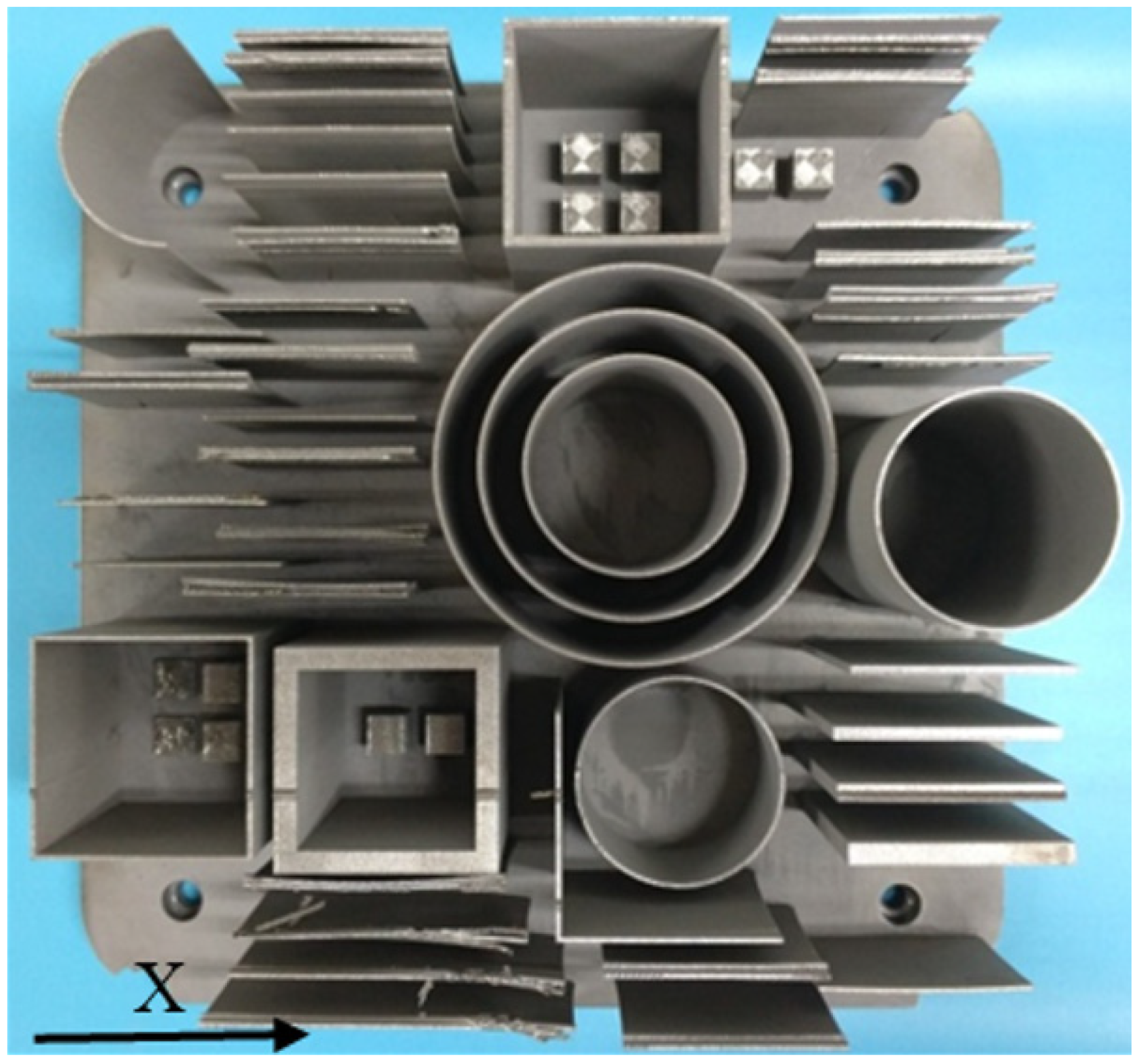
  • Single-wall structures of different thicknesses and heights;
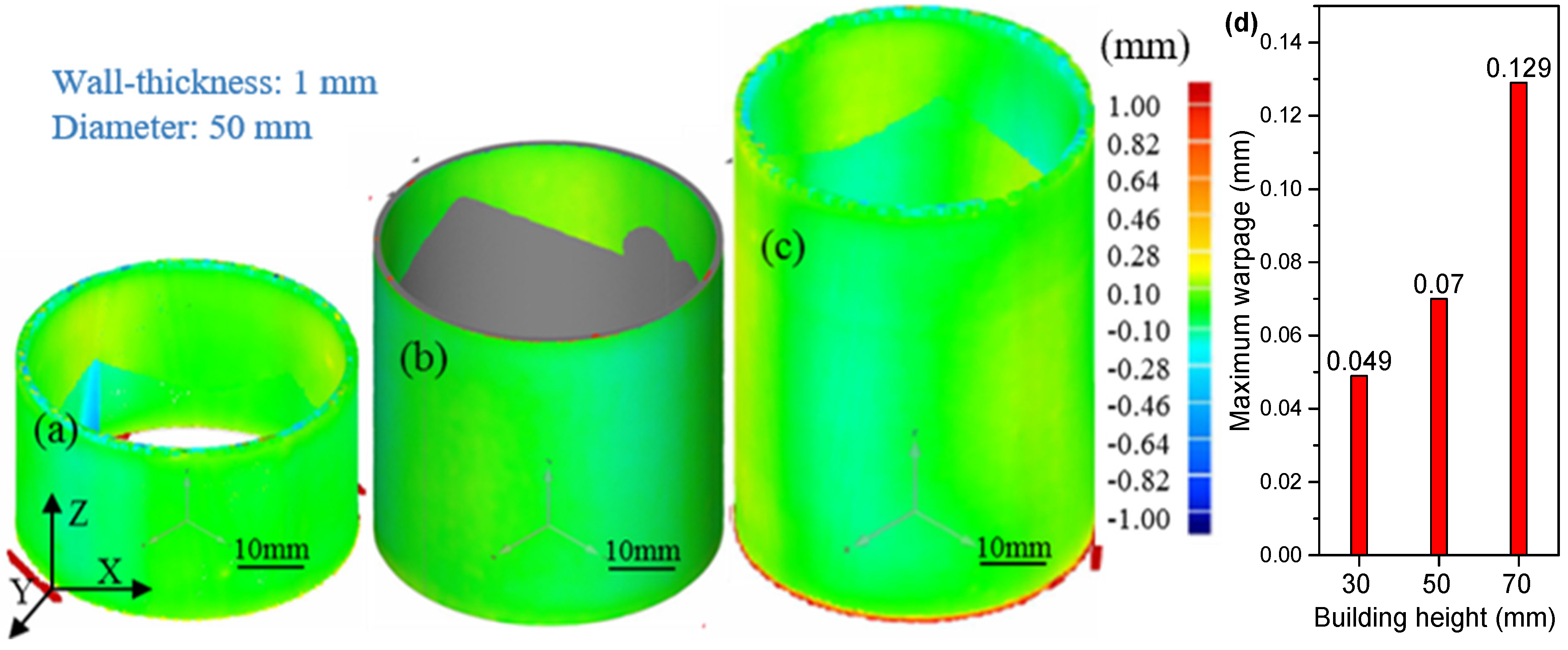
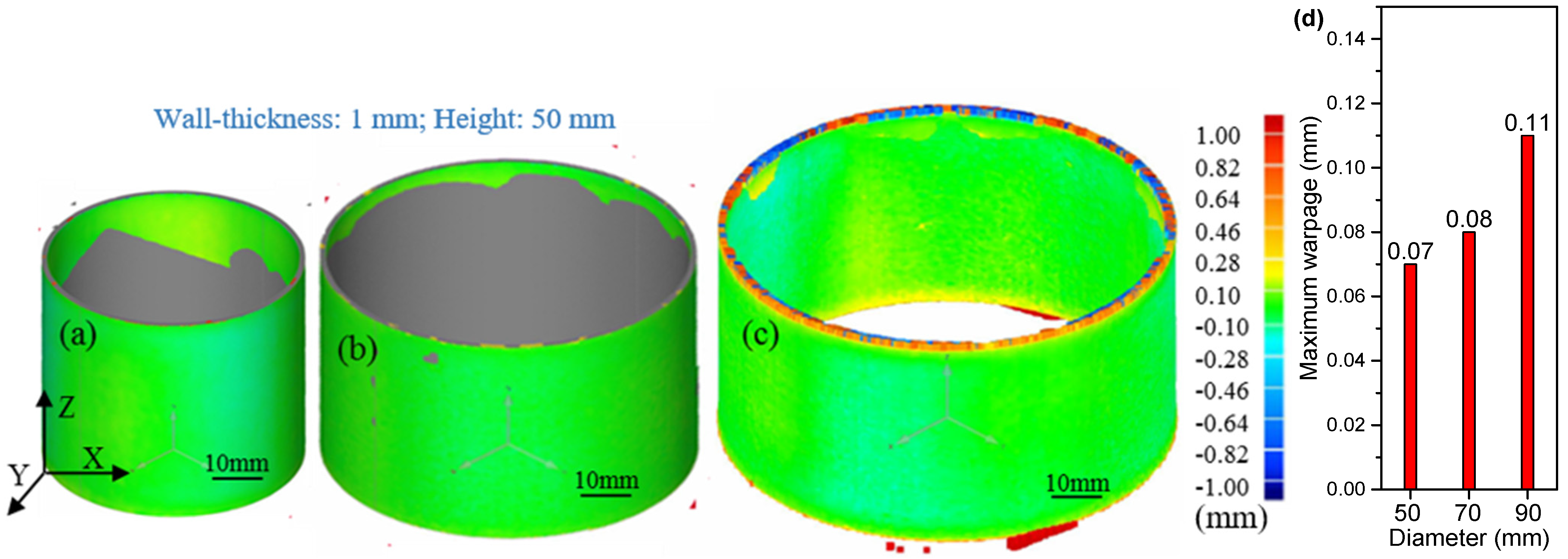
  • Cylindrical structures of different diameters and heights;
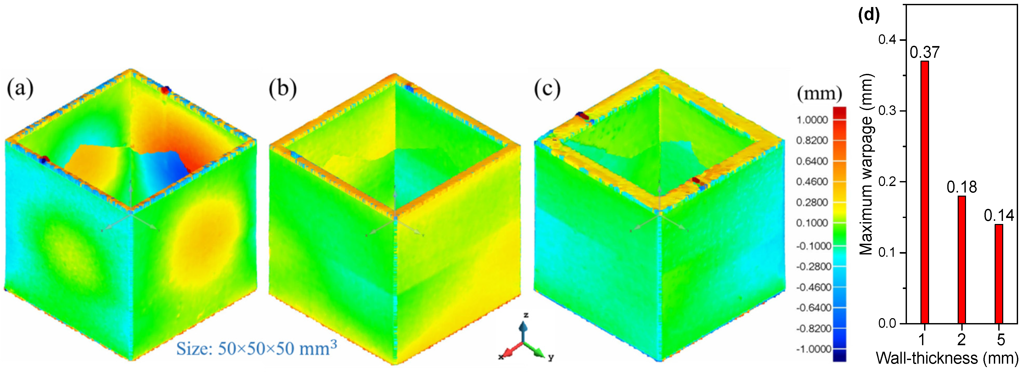
  • Square-section structures of several thicknesses;
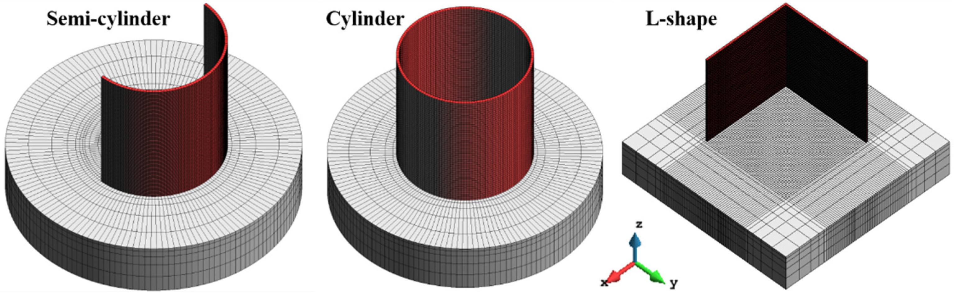
  • Open-section structures (e.g., semi-cylinder, L-shape, etc.).
Figure 2 shows the Breuckmann SmartSCAN3D scanner (Aniwaa, Central Singapore, Singapore) with the measurement accuracy of 0.015 mm, used to measure the actual distortion of all the components after the 3D-printing process. The relative component warpage is calculated by the Geomagic Qualify software (3D Systems, Rock Hill, Washington, DC, USA) by comparing the experimental 3D-scan images with the nominal CAD geometries. It should be mentioned that all the measurements are done before the removal of the substrate (cutting phase).

Scale Effect on the Part Warpage

In this section, the sensitivity to the dimensions (e.g., wall-thickness, building height and component size) of the thin-walled components is examined. Therefore, the warpage is measured by 3D-scanning to obtain its relation with the actual dimensions of the 3D-printed structures.
The first assessment study considers a single-wall geometry with a base length of 50 mm and a total height of 50 mm. Three thicknesses of 1 mm, 2 mm and 5 mm, respectively, are investigated.
Figure 3 compares the final warpage distributions as measured for the three wall thicknesses used. It can be seen that the thinnest wall presents the more pronounced warpage, up to 0.41 mm in the middle of the final cambered surface. As the wall-thickness increases, the warpage rapidly decreases; the maximum out-of-plane displacement for the 5 mm thickness wall is only of about 0.03 mm. Hence, as the thickness is increased, the wall warpage is restrained by the enhanced structural stiffness of the component. Simultaneously, higher residual stresses are induced by the printing process.
A second study analyses three different wall heights (37 mm, 43 mm and 50 mm, respectively) for the same single-walled geometry and a fixed thickness of 1 mm. Figure 4 compares the residual warpages of the three thin-walled structures. It is possible to observe that increasing the component height results in larger part warpage. This is not only because of the reduced wall thickness, but also because the higher the component, the less sensitive it is to the clamping conditions at the base and, thus, the more free it is to deform.
Next, a closed thin-wall cylindrical structure is studied. The diameter is 50 mm and the wall thickness is to 1 mm. The cylinder heights are of 30 mm, 50 mm and 70 mm, respectively.
Figure 5 shows the contour-fills of the warpage for the three cylindrical structures with different heights. It can be found that increasing the height leads to larger warpages as observed for the single-wall. However, the maximum warpage is remarkably lower than in both the single-wall and the square thin-wall structures. In this case, the (cylindrical) shape noticeably improves the structural stiffness of the printed structure for the same reduced wall thickness and component height.
A further assessment study is performed assuming a thin-wall cylindrical geometry with a thickness of 1 mm and a height of 50 mm. Different cylinder diameters of 50 mm, 70 mm and 90 mm are studied. Figure 6 depicts the contour-fills of the final warpage of the three cylinders. As expected, by increasing the diameter, the warpage is also more pronounced. Eventually, if very large diameters are considered, the results of the open single-wall should be replicated.
Finally, the last assessment studies a closed square thin-wall section. The same base length and height of 50 mm are used, while wall thicknesses of 1 mm, 2 mm and 5 mm are investigated. Figure 7 shows the contour-fills of the residual warpage for the three AM structures. Once again, it can be observed that the thicker the wall-thickness, the smaller the observed warpage. Therefore, a pronounced bulging is shown by the component with the thinnest wall. Nevertheless, the overall structural stiffness of the closed section allows for a reduction of the maximum out-of-plane displacements: 0.37 mm compared to 0.41 mm as measured for the open single-wall. This is because the deformation of each one of the walls conforming the square thin-wall section is constrained by the substrate and also laterally. Notably, the cylinder of similar dimensions shows a much better performance than the square thin-wall section of similar dimensions, Figure 5b and Figure 7a, respectively. This is explained as follows. In LPBF, high tensile stresses in the hoop/wall direction exist at the top for two components. Large tensile stresses also happen along the corners of the square part due to the high cooling rates at such locations; this builds up compressive stresses in the central region of each square wall so that any small disturbance can favour the bulging perpendicular to the wall. This is not the case for the cylinder.

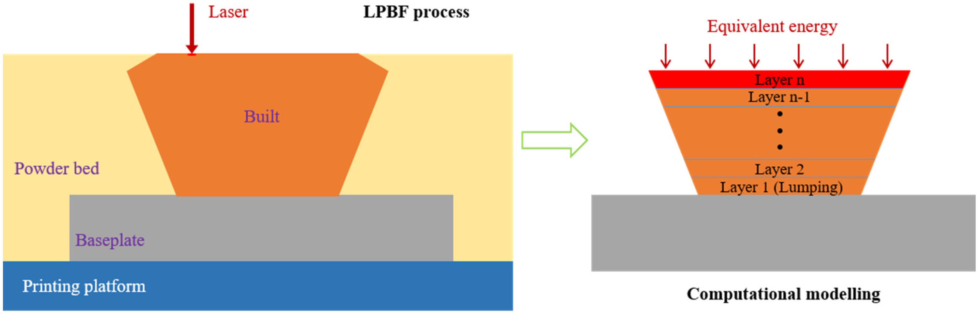
3. Numerical Modeling

In LPBF the following two operations are repeated for each layer (see Figure 8):
  • Recoating: the baseplate is lowered to accommodate a new powder layer;
  • Laser-scanning: the laser heat source generates a molten pool which follows a user-defined trajectory to selectively melt the powder bed consolidating the new layer comprising the AM build.
The most suitable numerical strategy to approach the simulation of the LPBF process is by the inherent strain method [32]. This method allows for a fast prediction of the distortions and residual stresses of the fabricated component. Therefore, the detailed simulation of the laser movement along the scanning trajectory is replaced by a layer-by-layer (or even multi-layer) analysis. This assumption is generally accepted when simulating LPBF processes because the scanning speed is very high (up to 1 m/s) compared to other AM technologies and the TMAZ is very localized, and it affects only the last few (2–3) layers. As a consequence, thermo-plastic (inherent) strains are only generated within the TMAZ.
This given, the original CAD geometry is firstly sliced according to the thickness of the powder-bed and then the FE discretization is generated accordingly. The birth-death FE activation technique is adopted [19,33] to progressively add the elements belonging to each new layer to the computational domain, Ω. In the initial FE discretization of the nominal CAD geometry, all elements are inactive. Inactive elements are not computed or assembled into the global system of equations. The numerical simulation of the building process consists of a sequence of layer activations. Hence, at each time-step, the elements belonging to the next layer are switched on (activated), becoming part of the current computational domain. For each time-step, the thermo-mechanical analysis is performed for all the active elements, until the whole layer-by-layer deposition sequence is completed.

3.1. Mechanical Problem

The stress analysis enforces the conservation of the balance of momentum and the continuity equations within the current active domain:
s + ▽p + b = 0
(▽ueT) − p/K = 0
where b are the body forces per unit of volume and K(T) is the temperature-dependent bulk modulus and p and s, are the hydrostatic (pressure) and the deviatoric components of the Cauchy stress tensor, σ. Thus:
σ = pI + s
The strain tensor, ε(u) = ▽su, can also be split in its volumetric and deviatoric parts, evol = ▽·u and e, respectively, so that:
ε = evolI/3 + e
The deviatoric stress tensor is computed as:
s(u) = 2G(e(u) − einh)
where G(T) is the temperature-dependent shear modulus and einh is the inherent strain tensor, as:
einh = eTI + evp
which typically includes both the thermal deformation, eT(T), and the visco-plastic strains, evp.
Commonly, the inherent strain method does not contemplate the solution of the thermal problem. Therefore, the inherent strain tensor is assumed as a (constant) user-defined material parameter depending on the material and process characterization. Its value can be obtained either experimentally or numerically, through the detailed simulation of the molten pool solidification.
In this work, a staggered thermo-mechanical solution is adopted to solve the AM problem [34,35]. Therefore, both the thermal and the mechanical analyses are carried out in a layer-by-layer manner. On the one hand, the thermal deformations can be computed from the actual (non-uniform) temperature field (inherent shrinkage method). On the other hand, the (inherent) visco-plastic deformations are defined as:
evp = diag(el, et, ez) = I(el, et, ez)T
where el, et and ez are the longitudinal (aligned with the scanning direction), transversal and vertical (building direction) visco-plastic components, respectively [33,34,35]. In LPBF, the thickness of the deposited layer is very small, so ez can be neglected. Additionally, thin-walled parts can be assumed to be in a quasi-plane-stress condition, so that the only inherent strain component to be considered is the one along the mid-line of the cross-section, regardless of the scanning pattern.

3.2. Thermal Problem

H being the hatch spacing, the total travelled scanning length for each layer is:
lscan = A/H
where A is the area of the current layer. The volume of the Heat Affected Zone (HAZ) is given by:
VHAZ = lscan × d × s = (d/H) × (s/t) × V
where d is the laser beam diameter and s is the penetration (depth) of the melt-pool, while V = A·t is the volume of the layer, being t its thickness. In this work, d = H (no overlapping) and s = t (the melt-pool depth is the layer thickness). Thus, the volume of the HAZ corresponds to the volume of the layer being activated.
Hence, the heat source density accounting for the total energy input during the scanning sequence of the whole layer is computed as:
q = ηP/V
where η is the laser absorptivity and P is the laser power. This heat source is delivered during the whole scanning phase, which is characterized by a time interval, Δtscan computed as:
Δtscan = lscan/Vscan = A/(H × Vscan)
where Vscan is the scanning velocity. Observe that the LPBF process also includes the recoating operation, that is a cooling phase of duration Δtcool.
Often, the thermo-mechanical analysis is accelerated by lumping several layers into a single time-step. Therefore, the equivalent time-step of the analysis results in:
Δteq = n·(Δtscan + Δtcool)
where n is the number of lumped layers (in this work n = 10) and the power input is uniformly spread in the lumped volume, Vlump, so that:
qeq = ηP/Vlump

3.3. Geometrical Models and FE Meshes

The coupled thermo-mechanical analysis is performed using the in-house FE software, COMET, developed at the International Centre for Numerical Methods in Engineering (CIMNE) [36,37]. The definition of the CAD geometries, and the corresponding the FE mesh generation as well as the pre/post-processing operations are carried out using the in-house pre/post-processor GiD [38]. The hardware used to run the simulation incorporates an Intel(R) Core (TM) i7-9700, 3.0 GHz processor and 16.0 GB of RAM.
Figure 9 shows the FE meshes of three different thin-walled geometries including both open and closed structures with a fixed thickness of 1 mm. The dimensions of these structures and the corresponding numbers of the hexahedral elements and nodes are listed in Table 3.
The average mesh size in all cases is of about 1 × 1 mm2 within the horizontal XY plane, and 0.3 mm in the building direction (a lumping layer-height). All these thin-walled work-pieces have the same height of 50 mm. The LPBF process is simulated with a sequence of 167 time-steps through a layer-by-layer activation strategy. Each layer used for the simulation has a thickness of 0.3 mm, thus including 10 physical layers (30 µm of loose powder is spread at each recoating step).
The temperature-dependent thermal and mechanical properties used to feed the constitutive model of Ti-6Al-4V alloy have been calibrated in a previous work [5], as shown in Table 4.
The thermal boundary conditions adopted in all the proposed analyses are defined through a heat convection coefficient of 12.7 W/(°C·m2) and an emissivity of 0.35 [39]. The ambient temperature is set to 26°C during the whole LPBF process. The efficiency of the LPBF process, when Ti-6Al-4V loose powder is used, is defined in terms of the heat power absorption coefficient fixed to η = 0.4 [39].
All the thin-walled structures are printed at the same time (see Figure 1). Nevertheless, the simulation strategy assumes that each component is printed separately. This is because the heat conductivity of the loose powder is extremely low, so that most of the heat is evacuated by radiation through the upper surface of the layer being printed as well as by heat conduction through the baseplate. Therefore, the in-plane (XY) heat flux through the loose powder is negligible compared to the heat flow in the vertical (building) direction.

4. Calibration and Results

4.1. Calibration of the Numerical Model

In order to calibrate the numerical model used for LPBF, the warpage profiles of the thin-wall semi-cylindrical, cylindrical and L-shaped structures are computationally predicted and compared with the experimental 3D-scan results.
Figure 10a,b shows the out-of-plane displacements of the semi-cylindrical and cylindrical parts, respectively. The displacements at several control points are specifically used as a reference to assess the accuracy of the simulation. Similarly, Figure 11 compares the experimental and computed displacements of the L-shaped part. Once calibrated, the numerical model is able to faithfully reproduce the experimental results obtained by 3D scanning.
It can be seen in Figure 10a that a visible bulge (of approximately 0.4 mm) occurs at opposite sides of the semi-cylindrical part, while the cylindrical geometry just shows very small radial displacements (less than 0.08 mm), these being more pronounced in the mid-section. The open L-shaped thin-wall structure also shows large deformations at the edges of each wall, as shown in Figure 11 and successfully predicted by the numerical model.
The slight discrepancies between the experimental and computed results are attributed to the mutual thermal influence among all the components as they are printed together (see Figure 1); this influence is disregarded in the FE simulation.

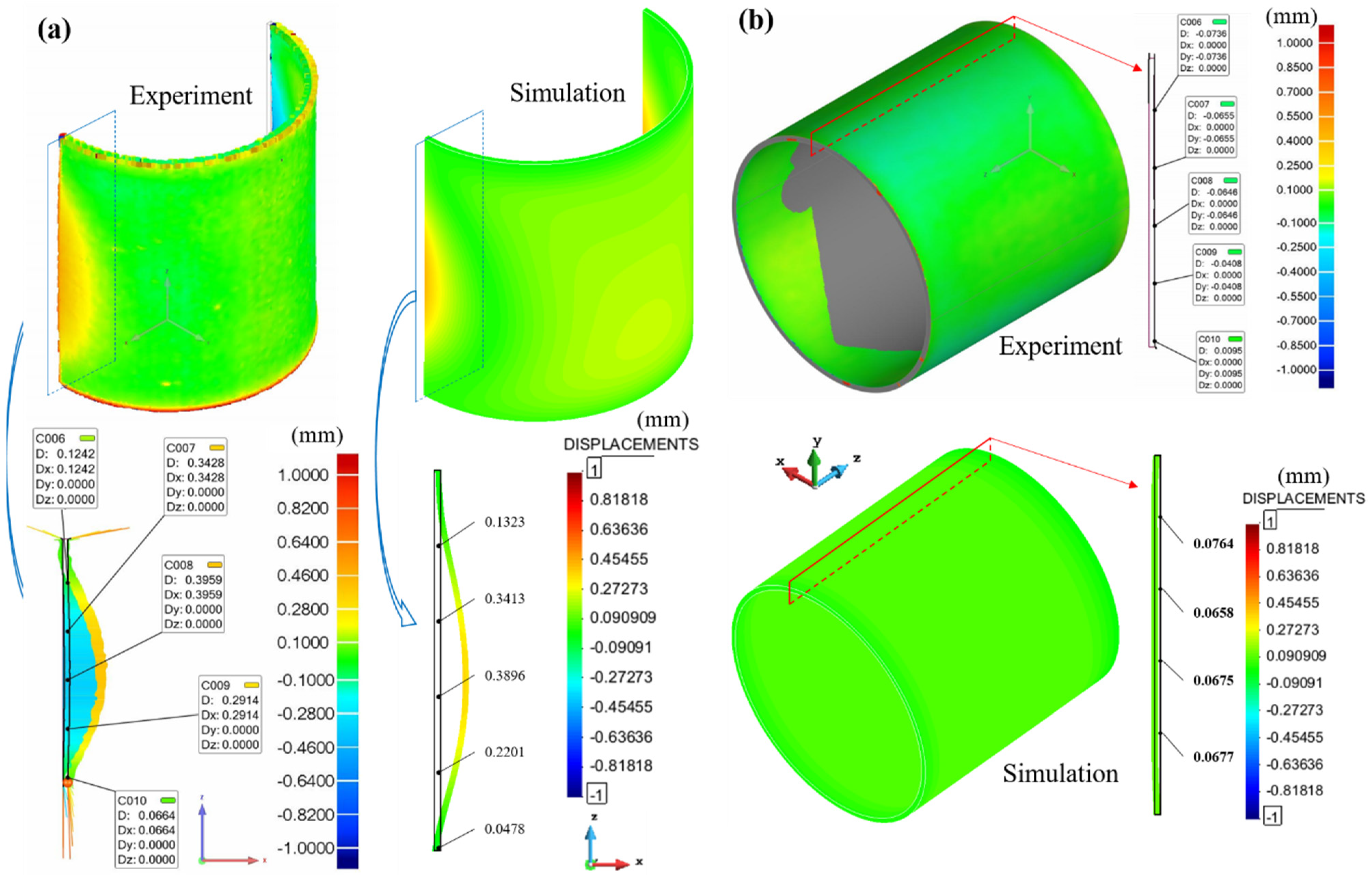
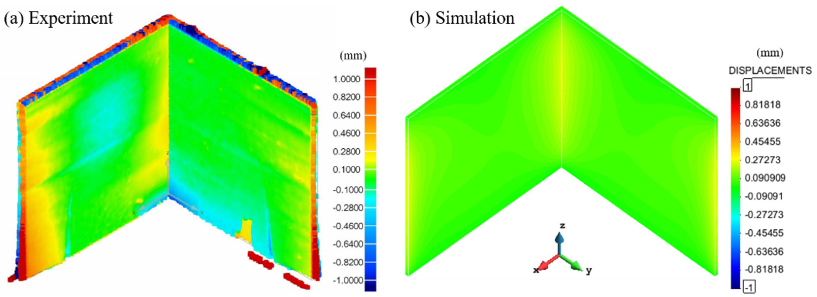
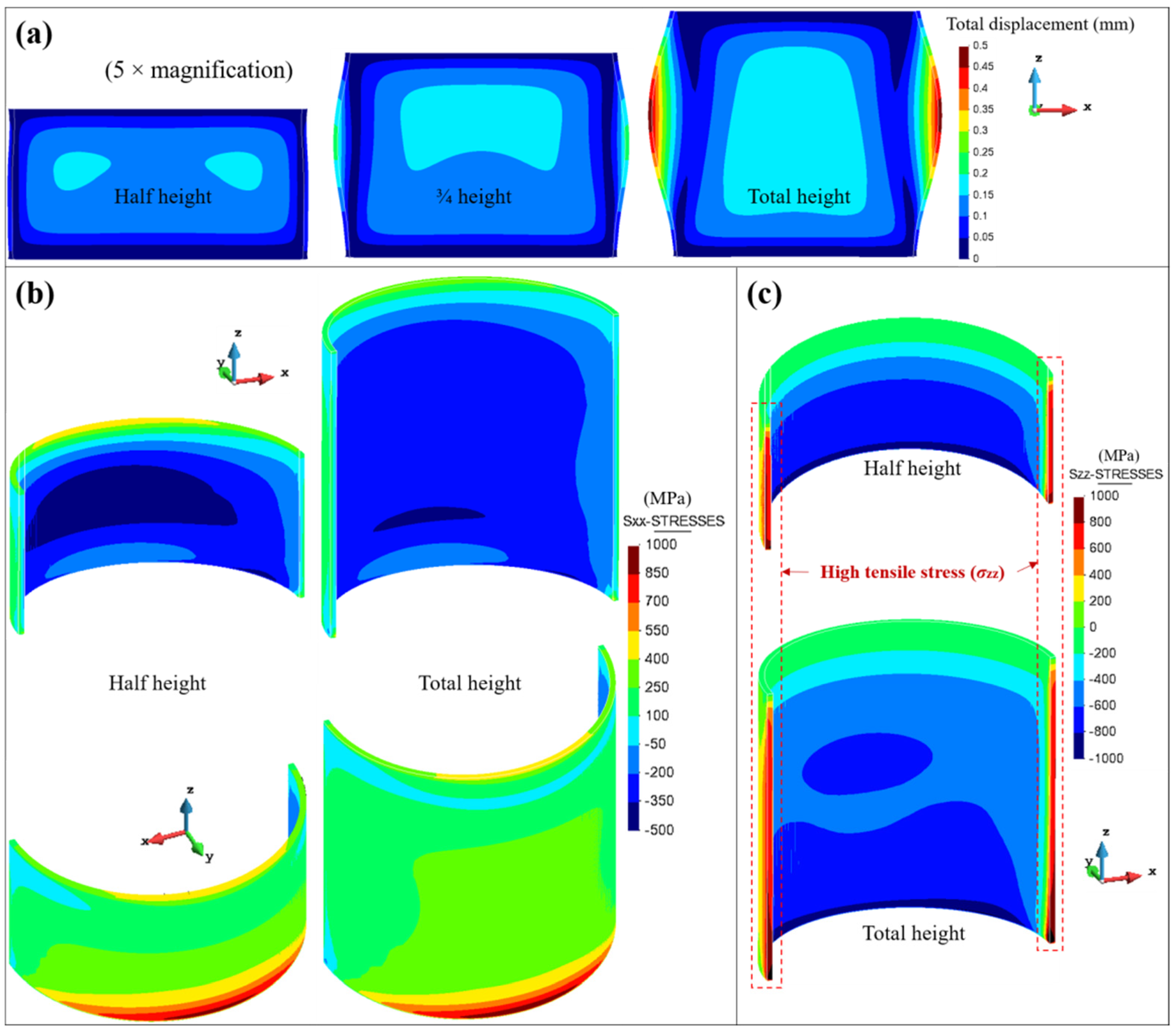
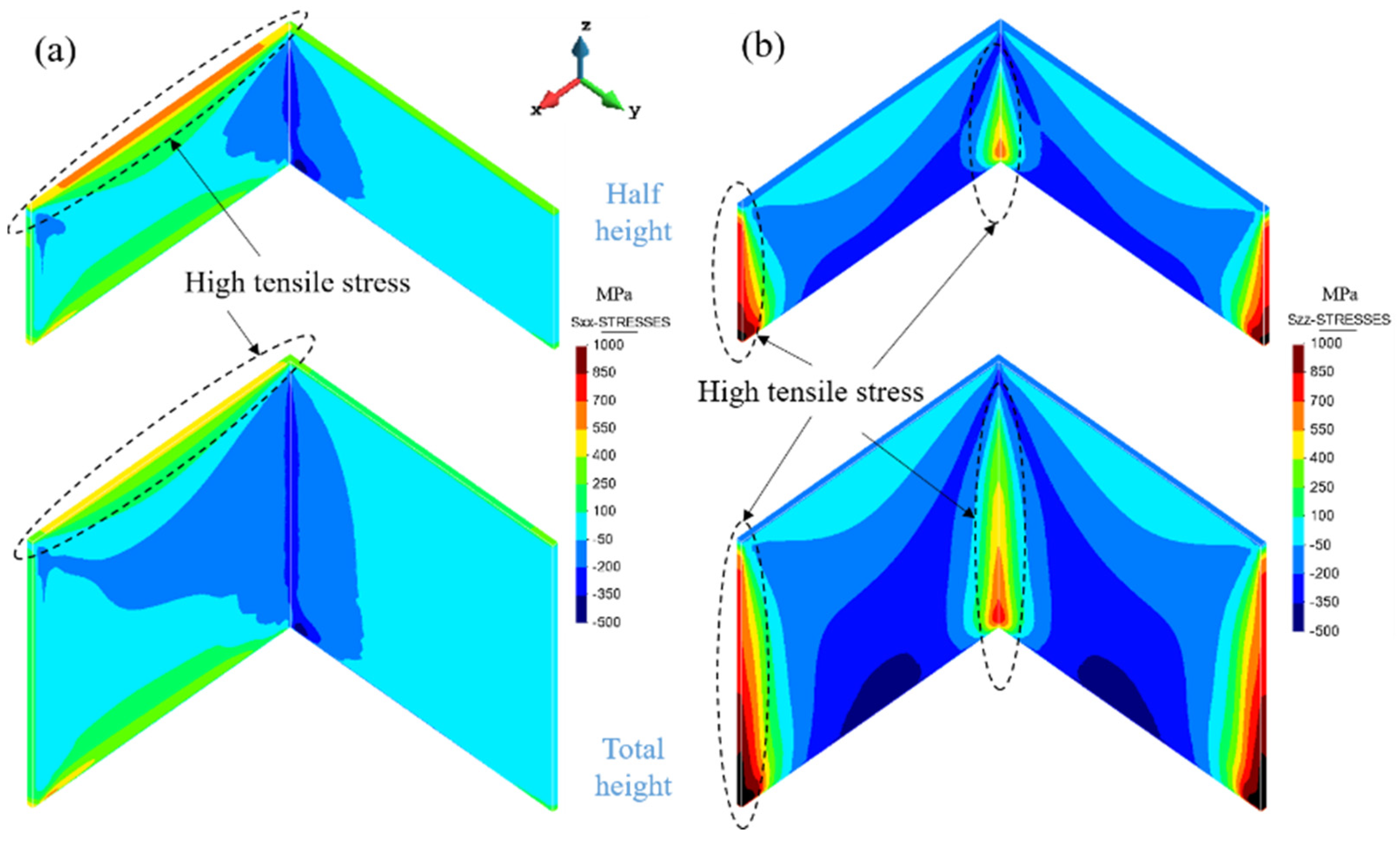
4.2. Results and Discussion on the Warpage Mechanism of the Thin-Walled Structures

Understanding the mechanical response of the 3D-printed geometries is necessary to establish a procedure to alleviate the warpage phenomenon in LPBF manufacture. As an example, the above results clearly illustrate that open thin-wall structures are more prone to deformation than closed ones.
Focusing on the open thin-walled semi-cylindrical geometry (Figure 10a), it is observed that the formation of the bulging progresses as the LPBF printing process moves away from the substrate as shown in Figure 12a. The bulging gets more pronounced when printing the upper half of the component because the mechanical constraining from the substrate restrains the development of the distortion in the bottom half. Figure 12b,c shows the evolution of the longitudinal and vertical stresses, σxx and σzz, respectively, at two stages of the manufacturing. It can be noted in Figure 12b that the internal surface sustains compressive stresses while tensile stresses are induced in the external surface. As a consequence, the wall deforms outwards. The vertical tensile stresses induced by the high cooling rate and the small bending stiffness of these structures also promote the bulging as shown in Figure 12c.
Contrarily, the closed thin-walled cylindrical part presents a much higher structural stiffness, and thus the AM process only produces a small deformation in the radial direction.
Dunbar et al. [40] studied the warpage of two thin-walled cylinders built by SLM. They also found that the warpage is relatively small. Throughout the printing process, the maximum warpage occurs several layers below the most recently deposited layer. This confers a final concave shape to the component.
Next, the warpage mechanism of the thin-wall L-shape structure is analyzed. Figure 13 shows the evolution of the longitudinal stresses (σxx) and the vertical stresses (σzz). During the building process, large tensile stresses develop at the top and two side edges while compressive stresses are produced in the central area of the built. As a result, warpage is visible along the lateral edges (see Figure 11). Note that a similar stress distribution and bulging phenomenon also take place when fabricating the single-wall and the square thin-walled section (see Figure 4 and Figure 5).
Yang et al. [41] also carried out a distortion analysis of thin-walled L-shaped and cross structures; their results showed that the side with longitudinal scan suffers larger distortion, whereas the side with transverse scan is distortion-free. Obviously, the mechanical response of thin-walled structures is closely related with the scan strategy.

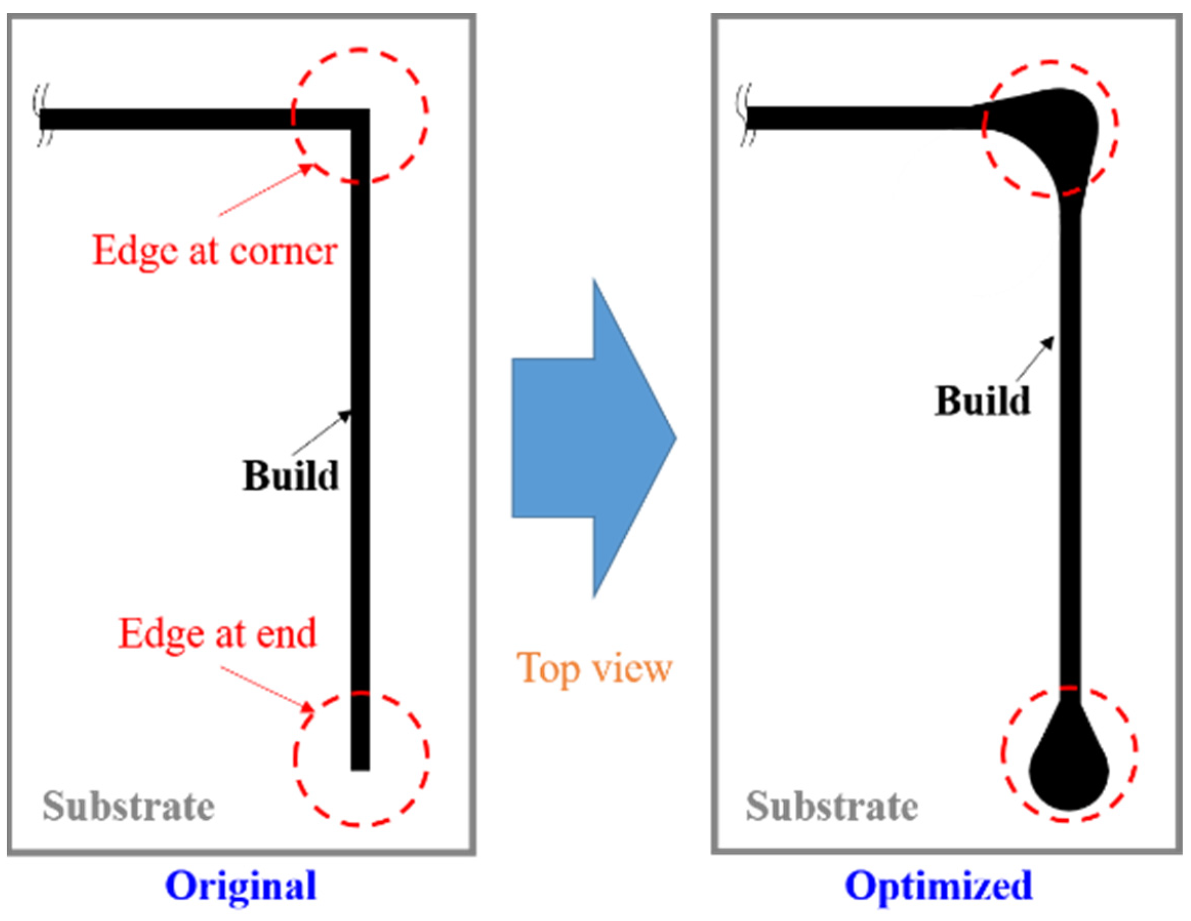
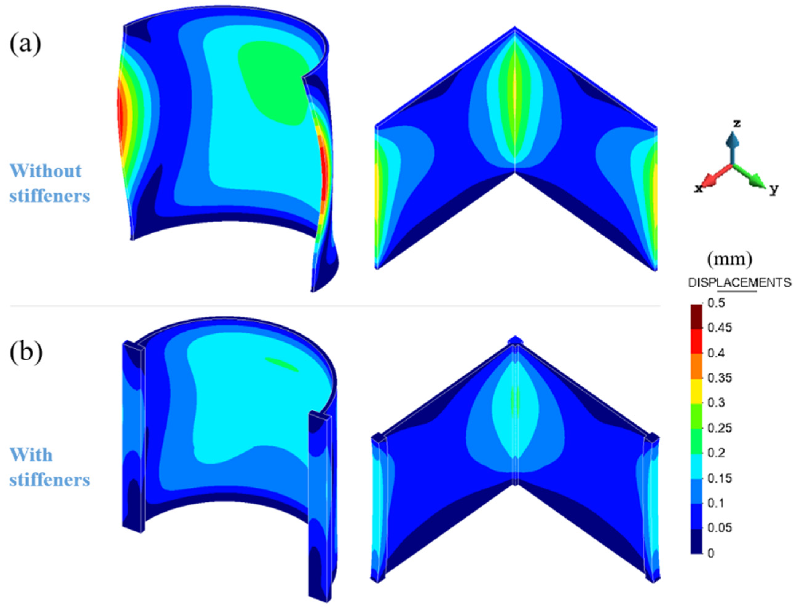
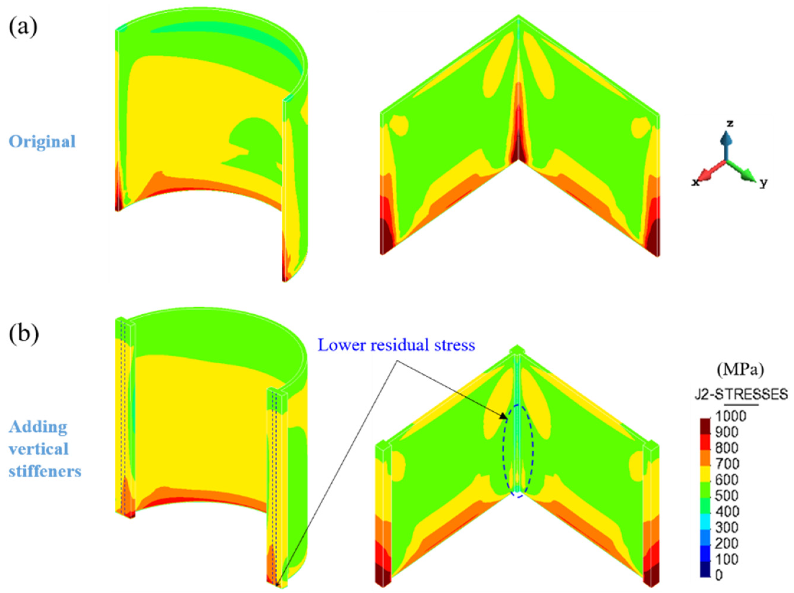
5. Structural Optimization for Warpage Control

As above mentioned, the main difficulty for fabricating thin-walled AM components is their low structural stiffness and the high thermal stresses, especially at the sharp corners. In order to minimize the part warpage, a structural optimization strategy is proposed to enhance the overall stiffness of the component and particularly when open sections must be fabricated. The idea consists in adding vertical stiffeners able to resist the thermal stresses by locally increasing the structural stiffness and, at the same time, reducing the cooling rate at the edges of AM components as shown in Figure 14.
Figure 15 shows the final warpage of both the open semi-cylindrical and L-shaped thin-walled parts with and without the vertical stiffeners. The warpage minimization is noticeably achieved.
Figure 16 shows the residual von Mises stresses of the open semi-cylindrical and L-shaped thin-walled structures. These residual stresses are mitigated by lowering the cooling rates at the edges of the two structures, thus increasing the local heat accumulation. Note that there still exist large residual stresses in the bottom area of both components. However, substrate preheating just before LPBF can successfully mitigate the residual stresses in this area to achieve high-quality fabrication of thin-walled components [5,7].

6. Conclusions

In this work, the warpage of several thin-walled structures fabricated by LPBF is investigated. The major conclusions of this study are:
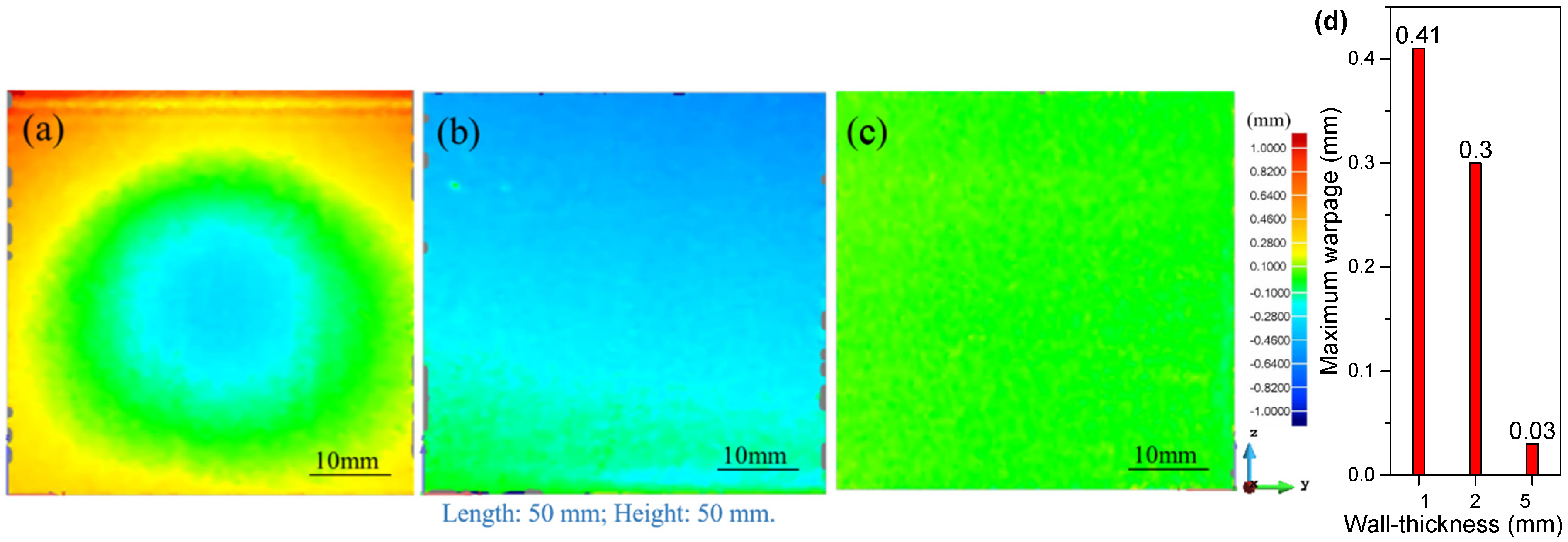
  • The wall thickness plays a significant role on the warpage of the final part. Thicker walled structures present reduced warpage.
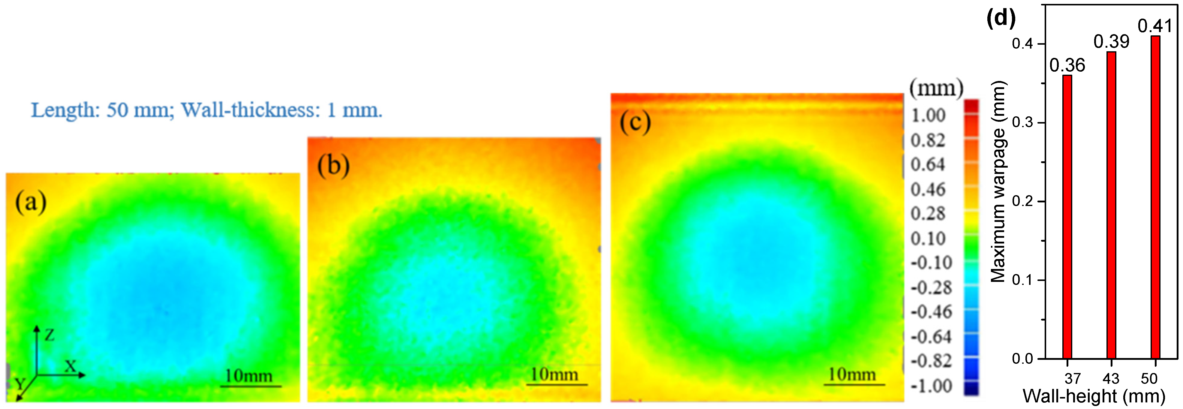
  • Increasing the build height as well as reducing the wall curvature causes larger warpage, as shown for the cylindrical structures.
  • Open sections (e.g., semi-cylinder, L-shape, etc.) are more prone to warpage than closed ones (e.g., cylinder and square section) because of their reduced structural stiffness.
  • The use of vertical stiffeners enables locally enhancing the structural stiffness of thin-walled structures, minimizing the residual warpage induced by the LPBF process.
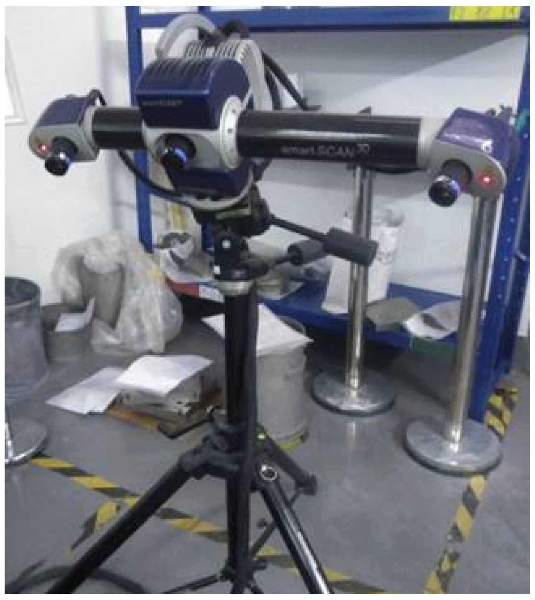
  • FE analysis of LPBF processes is a useful tool to analyse different thin-walled structures in order to predict the actual warpage. The developed FE model has been calibrated with experimental 3D-scanning images.

Author Contributions

Conceptualization, X.L. (Xufei Lu) and M.C. (Michele Chiumenti); methodology and software, M.C. (Miguel Cervera) and H.T.; data curation, S.W. and X.L. (Xufei Lu); writing—original draft preparation, X.L. (Xufei Lu) and M.C. (Michele Chiumenti); writing—review and editing, M.C. (Miguel Cervera), and X.L. (Xin Lin); supervision, H.T. and X.L. (Xin Lin). All authors have read and agreed to the published version of the manuscript.

Funding

This work was funded by the National Key Technologies R & D Program (No. 2016YFB1100104), the European KYKLOS 4.0 project (An Advanced Circular and Agile Manufacturing Ecosystem based on rapid reconfigurable manufacturing process and individualized consumer preferences—Grant Agreement No. 872570), the Severo Ochoa Programme for Centres of Excellence in R&D (CEX2018-000797-S) and the China Scholarship Council (No. 201906290011).

Data Availability Statement

Data are contained within the article.

Conflicts of Interest

The authors declare no conflict of interest.

References

  1. Herzog, D.; Seyda, V.; Wycisk, E.; Emmelmann, C. Additive manufacturing of metals. Acta Mater. 2016, 117, 371–392. [Google Scholar] [CrossRef]
  2. DebRoy, T.; Wei, H.L.; Zuback, J.S.; Mukherjee, T.; Elmer, J.W.; Milewski, J.O.; Beese, A.M.; Wilson-Heid, A.; De, A.; Zhang, W. Additive manufacturing of metallic components—Process, structure and properties. Prog. Mater. Sci. 2018, 92, 112–224. [Google Scholar] [CrossRef]
  3. Lu, X.; Zhao, T.; Ji, X.; Hu, J.; Li, T.; Lin, X.; Huang, W. 3D printing well organized porous iron-nickel/ polyaniline nanocages multiscale supercapacitor. J. Alloys Compd. 2018, 760, 78–83. [Google Scholar] [CrossRef]
  4. Zheng, M.; Wei, L.; Chen, J.; Zhang, Q.; Zhong, C.; Lin, X.; Huang, W. A novel method for the molten pool and porosity formation modelling in selective laser melting. Int. J. Heat Mass Transf. 2019, 140, 1091–1105. [Google Scholar] [CrossRef]
  5. Lu, X.; Lin, X.; Chiumenti, M.; Cervera, M.; Li, J.; Ma, L.; Wei, L.; Hu, Y.; Huang, W. Finite element analysis and experimental validation of the thermomechanical behavior in Laser Laser Directed energy deposition of Ti-6Al-4V. Addit. Manuf. 2018, 21, 30–40. [Google Scholar]
  6. Cao, J.; Gharghouri, M.A.; Nash, P. Finite-element analysis and experimental validation of thermal residual stress and distortion in electron beam additive manufactured Ti-6Al-4V build plates. J. Mater. Process. Technol. 2016, 237, 409–419. [Google Scholar] [CrossRef]
  7. Lu, X.; Lin, X.; Chiumenti, M.; Cervera, M.; Hu, Y.; Ji, X.; Ma, L.; Yang, H.; Huang, W. Residual stress and distortion of rectangular and S-shaped Ti-6Al-4V parts by Directed Energy Deposition: Modelling and experimental calibration. Addit. Manuf. 2019, 26, 166–179. [Google Scholar] [CrossRef]
  8. Lu, X.; Lin, X.; Chiumenti, M.; Cervera, M.; Hu, Y.; Ji, X.; Ma, L.; Huang, W. In situ Measurements and Thermo-mechanical Simulation of Ti-6Al-4V Laser Laser Directed energy deposition Processes. Int. J. Mech. Sci. 2019, 153, 119–130. [Google Scholar] [CrossRef]
  9. Liu, Y.J.; Liu, Z.; Jiang, Y.; Wang, G.W.; Yang, Y.; Zhang, L.C. Gradient in microstructure and mechanical property of selective laser melted AlSi10Mg. J. Alloys Compd. 2018, 735, 1414–1421. [Google Scholar] [CrossRef]
  10. Fang, Z.C.; Wu, Z.L.; Huang, C.G.; Wu, C.W. Review on residual stress in selective laser melting additive manufacturing of alloy parts. Opt. Laser Technol. 2020, 129, 106283. [Google Scholar] [CrossRef]
  11. Lu, Y.; Wu, S.; Gan, Y.; Huang, T.; Yang, C.; Li, J.; Lin, J. Study on the microstructure, mechanical property and residual stress of SLM inconel-718 alloy manufactured by differing island scanning strategy. Opt. Laser Technol. 2015, 75, 197–206. [Google Scholar] [CrossRef]
  12. Zaeh, M.F.; Branner, G. Investigations on residual stresses and deformations in selective laser melting. Prod. Eng. 2009, 4, 35–45. [Google Scholar] [CrossRef]
  13. Vora, P.; Mumtaz, K.; Todd, I.; Hopkinson, N. AlSi12 in-situ alloy formation and residual stress reduction using anchorless selective laser melting. Addit. Manuf. 2015, 7, 12–19. [Google Scholar] [CrossRef] [Green Version]
  14. Lu, X.; Cervera, M.; Chiumenti, M.; Li, J.; Ji, X.; Zhang, G.; Lin, X. Modeling of the Effect of the Building Strategy on the Thermomechancial Response of Ti-6Al-4V Rectangular Parts Manufactured by Laser Directed Energy Deposition. Metals 2020, 10, 1643. [Google Scholar] [CrossRef]
  15. Yakout, M.; Elbestawi, M.; Veldhuis, S.; Nangle-Smith, S. Influence of thermal properties on residual stresses in SLM of aerospace alloys. Rapid Prototyp. J. 2020, 26, 213–222. [Google Scholar] [CrossRef]
  16. Chiumenti, M.; Neiva, E.; Salsi, E.; Cervera, M.; Badia, S.; Moya, J.; Chen, Z.; Lee, C.; Davies, C. Numerical modelling and experimental validation in Selective Laser Melting. Addit. Manuf. 2017, 18, 171–185. [Google Scholar] [CrossRef] [Green Version]
  17. Neiva, E.; Chiumenti, M.; Cervera, M.; Salsi, E.; Piscopo, G.; Badia, S.; Martín, A.F.; Chen, Z.; Lee, C.; Davies, C. Numerical modelling of heat transfer and experimental validation in powder-bed fusion with the virtual domain approximation. Finite Elem. Anal. Des. 2020, 168, 103343. [Google Scholar] [CrossRef]
  18. Lindgren, L.-E.; Lundbäck, A.; Malmelöv, A. Thermal stresses and computational welding mechanics. J. Therm. Stresses 2019, 42, 107–121. [Google Scholar] [CrossRef] [Green Version]
  19. Lundbäck, A.; Lindgren, L.-E. Modelling of metal deposition. Finite Elem. Anal. Des. 2011, 47, 1169–1177. [Google Scholar] [CrossRef]
  20. Williams, R.; Catrin, J.; Davies, M.; Hooper, P.A. A pragmatic part scale model for residual stress and distortion prediction in powder bed fusion. Addit. Manuf. 2018, 22, 416–425. [Google Scholar] [CrossRef]
  21. Baiges, J.; Chiumenti, M.; Moreira, C.A.; Cervera, M.; Codina, R. An Adaptive Finite Element strategy for the numerical simulation of Additive Manufacturing processes. Addit. Manuf. 2021, 37, 101650. [Google Scholar]
  22. Lu, X.; Chiumenti, M.; Cervera, M.; Li, J.; Lin, X.; Ma, L.; Zhang, G.; Liang, E. Substrate design to minimize residual stresses in Directed Energy Deposition AM processes. Mater. Des. 2021, 202, 109525. [Google Scholar] [CrossRef]
  23. Ramos, D.; Belblidia, F.; Sienz, J. New scanning strategy to reduce warpage in additive manufacturing. Addit. Manuf. 2019, 28, 554–564. [Google Scholar] [CrossRef]
  24. Levkulich, N.; Semiatin, S.; Gockel, J.; Middendorf, J.; Dewald, A.; Klingbeil, N. The effect of process parameters on residual stress evolution and distortion in the laser powder bed fusion of Ti-6Al-4V. Addit. Manuf. 2019, 28, 475–484. [Google Scholar] [CrossRef]
  25. Li, H.; Ramezani, M.; Chen, Z.; Singamneni, S. Effects of Process Parameters on Temperature and Stress Distributions During Selective Laser Melting of Ti-6Al-4V. Trans. Indian Inst. Met. 2019, 72, 3201–3214. [Google Scholar] [CrossRef]
  26. Afazov, S.; Denmark, W.A.; Toralles, B.L.; Holloway, A.; Yaghi, A. Distortion prediction and compensation in selective laser melting. Addit. Manuf. 2017, 17, 15–22. [Google Scholar] [CrossRef]
  27. Yaghi, A.; Ayvar-Soberanis, S.; Moturu, S.; Bilkhu, R.; Afazov, S. Design against distortion for additive manufacturing. Addit. Manuf. 2019, 27, 224–235. [Google Scholar] [CrossRef] [Green Version]
  28. Biegler, M.; Elsner, B.A.; Graf, B.; Rethmeier, M. Geometric distortion-compensation via transient numerical simulation for directed energy deposition additive manufacturing. Sci. Technol. Weld. Join. 2020, 25, 468–475. [Google Scholar] [CrossRef]
  29. Li, Z.; Xu, R.; Zhang, Z.; Kucukkoc, I. The influence of scan length on fabricating thin-walled components in selective laser melting. Int. J. Mach. Tools Manuf. 2018, 126, 1–12. [Google Scholar] [CrossRef]
  30. Chen, C.; Xiao, Z.; Zhu, H.; Zeng, X. Deformation and control method of thin-walled part during laser powder bed fusion of Ti–6Al–4V alloy. Int. J. Adv. Manuf. Technol. 2020, 110, 3467–3478. [Google Scholar] [CrossRef]
  31. Ahmed, A.; Majeed, A.; Atta, Z.; Jia, G. Dimensional Quality and Distortion Analysis of Thin-Walled Alloy Parts of AlSi10Mg Manufactured by Selective Laser Melting. J. Manuf. Mater. Process. 2019, 3, 51. [Google Scholar] [CrossRef] [Green Version]
  32. Setien, I.; Chiumenti, M.; Van Der Veen, S.; Sebastian, M.S.; Garciandía, F.; Echeverría, A. Empirical methodology to determine inherent strains in additive manufacturing. Comput. Math. Appl. 2019, 78, 2282–2295. [Google Scholar] [CrossRef] [Green Version]
  33. Chiumenti, M.; Lin, X.; Cervera, M.; Lei, W.; Zheng, Y.; Huang, W. Numerical simulation and experimental calibration of additive manufacturing by blown powder technology. Part I: Thermal analysis. Rapid Prototyp. J. 2017, 23, 448–463. [Google Scholar] [CrossRef] [Green Version]
  34. Chiumenti, M.; Cervera, M.; Salmi, A.; De Saracibar, C.A.; Dialami, N.; Matsui, K. Finite element modeling of multi-pass welding and shaped metal deposition processes. Comput. Methods Appl. Mech. Eng. 2010, 199, 2343–2359. [Google Scholar] [CrossRef]
  35. Chiumenti, M.; Cervera, M.; Dialami, N.; Wu, B.; Jinwei, L.; De Saracibar, C.A. Numerical modeling of the electron beam welding and its experimental validation. Finite Elem. Anal. Des. 2016, 121, 118–133. [Google Scholar] [CrossRef] [Green Version]
  36. Cervera, M.; de Saracibar, C.A.; Chiumenti, M. COMET: Coupled Mechanical and Thermal Analysis; Data Input Manual, Version 5.0, Technical Report IT-308; CIMNE: Barcelona, Spain, 2002. [Google Scholar]
  37. Dialami, N.; Cervera, M.; Chiumenti, M.; De Saracibar, C.A. A fast and accurate two-stage strategy to evaluate the effect of the pin tool profile on metal flow, torque and forces in friction stir welding. Int. J. Mech. Sci. 2017, 122, 215–227. [Google Scholar] [CrossRef] [Green Version]
  38. Ribó, R.; Pasenau, M.; Escolano, E.; Pérez, J.; Coll, A.; Melendo, A. GiD The Personal Pre and Postprocessor; Reference Manual; CIMNE: Barcelona, Spain, 2006. [Google Scholar]
  39. Zhang, W.; Tong, M.; Harrison, N.M. Resolution, energy and time dependency on layer scaling in finite element modelling of laser beam powder bed fusion additive manufacturing. Addit. Manuf. 2019, 28, 610–620. [Google Scholar] [CrossRef]
  40. Dunbar, A.J.; Denlinger, E.R.; Gouge, M.F.; Michaleris, P. Experimental validation of finite element modeling for laser powder bed fusion deformation. Addit. Manuf. 2016, 12, 108–120. [Google Scholar] [CrossRef]
  41. Yang, T.; Xie, D.; Yue, W.; Wang, S.; Rong, P.; Shen, L.; Zhao, J.; Wang, C. Distortion of Thin-Walled Structure Fabricated by Selective Laser Melting Based on Assumption of Constraining Force-Induced Distortion. Metals 2019, 9, 1281. [Google Scholar] [CrossRef] [Green Version]
Figure 1. Typical thin-walled structures printed by LPBF.
Metals 11 00686 g001
Figure 2. Breuckmann SmartSCAN3D scanner for the warpage measurements.
Metals 11 00686 g002
Figure 3. Residual warpage (out-of-plane displacement) for the single-wall structures for different wall-thicknesses: (a) 1 mm; (b) 2 mm; (c) 5 mm, respectively. (d) Maximum warpage recorded in the middle section.
Metals 11 00686 g003
Figure 4. Residual warpage contour-fills of the thin-walled structures with different heights: (a) 37 mm; (b) 43 mm; (c) 50 mm, respectively. (d) Maximum warpages recorded in the middle section.
Metals 11 00686 g004
Figure 5. Contour-fills of the final warpage of the cylindrical thin-wall structures with different building heights: (a) 30 mm; (b) 50 mm; (c) 70mm, respectively. (d) Maximum warpages recorded in the middle section.
Metals 11 00686 g005
Figure 6. Contour-fills of the final warpage of the cylindrical thin-wall structures with different diameters of: (a) 50 mm; (b) 70 mm; (c) 90 mm; (d) Maximum warpages recorded in the middle section.
Metals 11 00686 g006
Figure 7. Contour-fills of the final warpage of the square thin-wall section with different wall-thicknesses: (a) 1 mm; (b) 2 mm; (c) 5 mm, respectively. (d) Maximum warpages recorded in the middle section.
Metals 11 00686 g007
Figure 8. The schematic of the used layer-by-layer model for LPBF.
Metals 11 00686 g008
Figure 9. 3D FE mesh models of thin-walled structures.
Metals 11 00686 g009
Figure 10. Comparison of the out-of-plane displacement fields obtained through 3D scanning and numerical simulation: (a) semi-cylinder; (b) cylinder.
Metals 11 00686 g010
Figure 11. Comparison of the out-of-plane displacement fields obtained through (a) 3D scanning and (b) numerical simulation for the L-shaped structure.
Metals 11 00686 g011
Figure 12. Semi-cylindrical part: the evolutions of (a) total displacements and (b) longitudinal stresses (σxx) as well as (c) vertical stresses (σzz).
Metals 11 00686 g012
Figure 13. L-shape component: evolutions of (a) longitudinal stresses and (b) vertical stresses.
Metals 11 00686 g013
Figure 14. Proposed modification of the local stiffness of thin-walled structures.
Metals 11 00686 g014
Figure 15. Warpage of the open (a) semi-cylindrical and (b) L-shaped thin-walled parts with and without vertical stiffeners.
Metals 11 00686 g015
Figure 16. Residual von Mises stresses of the open (a) semi-cylindrical and (b) L-shaped parts with and without vertical stiffeners.
Metals 11 00686 g016
Table 1. Composition of Ti-6Al-4V alloy powder (wt.%).
AlVOHNCFeSiTi
6.283.900.0980.0020.0200.0080.0220.026Balance
Table 2. Processing parameters used in the PLBF process.
Laser Power
(W)
Layer Thickness
(µm)
Scan Speed
(mm/s)
Hatch Spacing
(µm)
Laser BeamDiameter
(µm)
200301000100100
Table 3. Dimensions of the proposed thin-walled structures and the numbers of FE elements and nodes.
Thin-Walled PartsDimensionsNumber of FE ElementsNumber of Nodes
Semi-cylindrical partΦ50 mm × H50 mm21,60637,618
Cylindrical partΦ50 mm × H50 mm34,63263,336
L-shaped partL50 mm × W50 mm × H50 mm34,36655,392
Table 4. Temperature-dependent material properties of Ti-6Al-4V alloy [5].
Temperature (°C)Density (kg/m3)Specific Heat (J/(kg·°C))Thermal Conductivity (W/(m·°C))Poisson’s RatioYoung’s Modulus (GPa)Thermal Dilatancy (μm/m/ °C)Yield Stress (MPa)
20442054670.3451108.78850
20543955848.750.3510010630
500435065112.60.377611.2470
995428275322.70.431512.313
1100426764119.30.43512.45
12004252660210.43412.421
1600419873225.80.43112.50.5
16503886831350.430.112.50.1
20003818831350.430.0112.50.01
Publisher’s Note: MDPI stays neutral with regard to jurisdictional claims in published maps and institutional affiliations.

