Review

A Review of Damage, Void Evolution, and Fatigue Life Prediction Models

Department of Civil, Structural and Environmental Engineering, University at Buffalo, New York, NY 14260-4300, USA
*
Author to whom correspondence should be addressed.
Metals 2021, 11(4), 609; https://doi.org/10.3390/met11040609
Submission received: 1 March 2021 / Revised: 31 March 2021 / Accepted: 6 April 2021 / Published: 9 April 2021
(This article belongs to the Special Issue New Trends in Fatigue of Metals)

Abstract

:
Degradation, damage evolution, and fatigue models in the literature for various engineering materials, mostly metals and composites, are reviewed. For empirical models established under the framework of Newtonian mechanics, Gurson–Tvergaard–Needleman (GTN) type model, Johnson-Cook (J-C) type damage model, microplasticity model, some other micro-mechanism based damage models, and models using irreversible entropy as a metric with an empirical evolution function are thoroughly discussed. For Physics-based models, the development and applications of unified mechanics theory is reviewed.

1. Introduction

The degradation, damage evolution, and fatigue behavior of materials are closely related to structural performance and safety. It is well-understood that engineering materials (such as metals and composites) have different micro-mechanisms, degradation processes, damage accumulation, and different failure modes dependent on many factors. For example, when the strain rate is around 10−6 to 10−5 s−1, creep can be a dominant mechanism; when around 10−4 to 10−3 s−1, it is defined as a quasi-static process; when above 103 s−1, it is usually regarded as a high strain rate, where inertia effects, thermal effects (e.g., adiabatic shear banding) and wave propagation influences must be taken into account [1].
In the following, we classify the damage, void evolution and fatigue life prediction models in the literature into two categories:
  • Empirical models are established under a Newtonian mechanics framework (this also includes Hamiltonian and Lagrangian mechanics). Regardless of the different techniques used to characterize the damage evolution with equations and some parameters, it primarily relies on the test data curve to fit the empirical void/damage evolution function. Examples include the Gurson–Tvergaard–Needleman (GTN) model [2], Rice-Tracey model [3], Gunawardena model [4], the well-known, strain rate dependent Johnson-Cook (J-C) damage model [5], some micro-mechanism based damage models, and models using irreversible entropy as a metric with an empirical evolution function. These empirical models are popular for engineering applications due to their simplicity. Still, the identification of parameters is costly, time-consuming, and lacks any scientific basis due to a lack of physical and mathematical foundations [6].
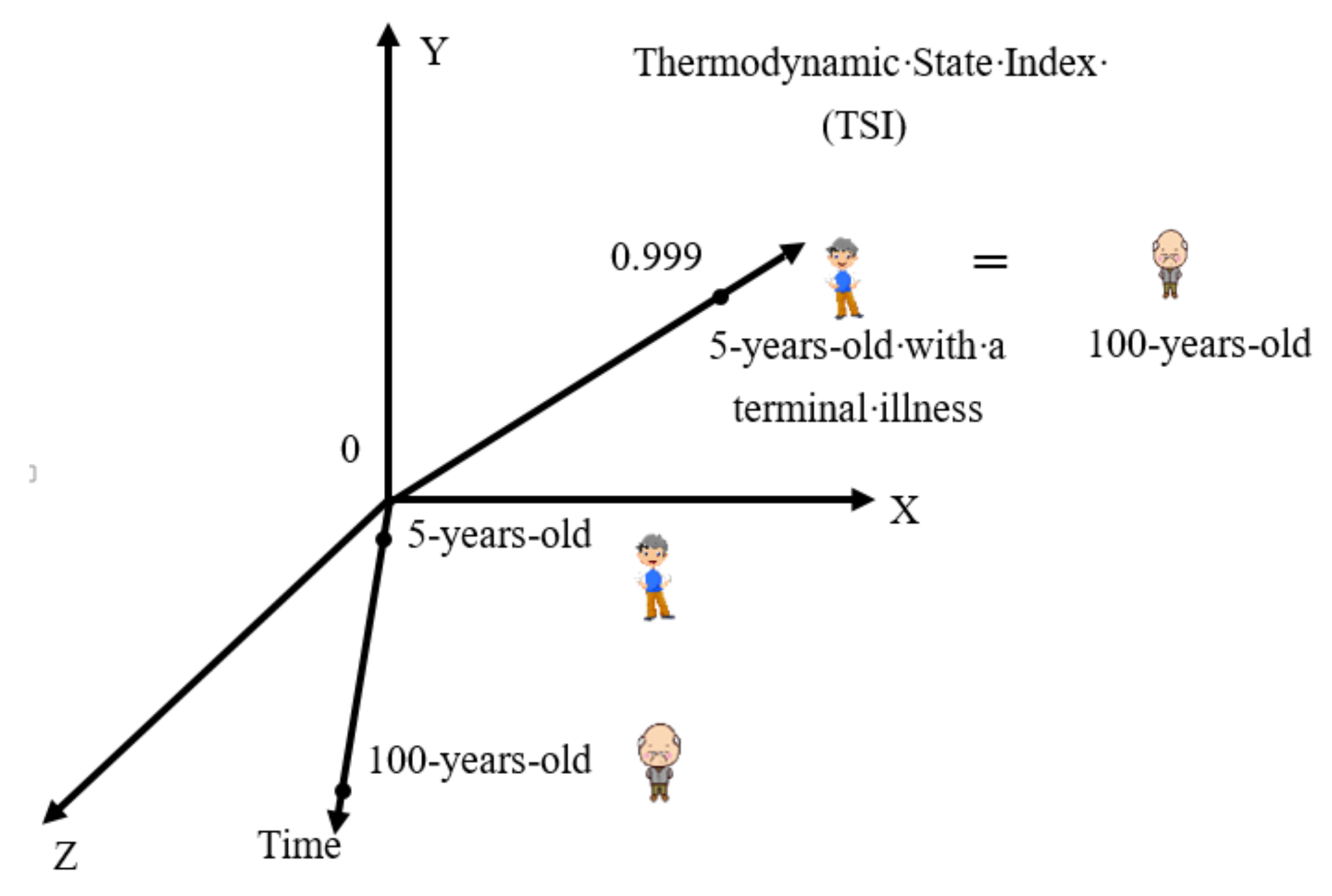
  • The physics-based models, on the other hand, as the name suggests, are based on the physical foundations and do not require curve fitting empirical functions to test data. They can be classified under the framework of Unified Mechanics Theory (UMT), incorporating the second law of thermodynamics directly into Newton’s laws at the ab-initio level [7]. As a result, governing differential equations of any system automatically include energy loss, entropy generation, and the system’s degradation in a non-empirical way. The UMT based models are pure physics-based and do not need curve fitting to any test data for the evolution of void/damage. However, they do require deriving analytical thermodynamic fundamental equations of the material without curve fitting. Thermodynamic fundamental equation and the second law of thermodynamics controls the evolution of damage along the fifth axis (Thermodynamic State Index axis), according to Boltzmann equation.
Some recent models for various engineering materials are reviewed in the following sections. They are categorized based on their approach and the type of material being investigated. In Section 2, empirical curve fitting models for metals including Gurson–Tvergaard–Needleman (GTN) type models, Johnson-Cook (J-C) type models, microplasticity models, and some other empirical models are discussed. Their equations are presented. In Section 3, some empirical curve fitting models developed for non-metallic materials are discussed. In Section 4, entropy based models are introduced and presented, including 1. Models using entropy as a damage metric with an empirical evolution function, and 2. Pure physics-based models using unified mechanics theory. Experimental verifications of physics-based models without simulations are also included. In Section 5, the effects of mechanical treatment including manufacturing techniques and surface finishing on surface integrity and fatigue performance are discussed.

2. Empirical Curve Fitting Models for Metals

2.1. Gurson–Tvergaard–Needleman (GTN) Model and Its Modified Form

GTN model [2,8] is a micromechanical empirical model based on the void nucleation, growth and coalescence in materials. Although it is widely used for the prediction of material ductile fracture behavior, it is limited to relatively high-stress conditions and gives inaccurate results when shear is involved [9,10,11]. For the strain rate effect, the incorporation of strain rate related terms on void growth and nucleation in the GTN model only allows the calculation for relatively low strain rate [6]. Therefore, it is incapable of solving high strain rate problems.
Considering these drawbacks, many researchers have adopted the GTN model and performed further modifications such as: 1. Including the damage mechanism due to shear, 2. Improving the applicability of the model under low stress triaxiality, 3. Combined with Johnson-Cook model to better describe the material ductile fracture process under high strain rate of loading. In the following sub-section, the original GTN model and the modified GTN models are introduced.
Acharya and Dhar [12] used the GTN model to predict the ductile failure of pipe. The GTN model’s empirical curve fitting parameters were properly chosen after the experimental results were obtained. Using the obtained parameters, they developed an elastic–plastic finite element code with GTN model for void nucleation and growth. The load versus load point displacement and the load versus crack growth of a pipe under four point bending is well computed by their FEM code incorporating GTN model. The GTN model they used can be expressed in the following form.
The yield function equation is given by
ϕ = σ e q σ m 2 + 2 q 1 f * cosh 3 2 q 2 σ h σ m 1 + q 3 f 2 = 0
where q 1 , q 2 , q 3 are empirical curve fitting parameters, σ e q is the von Mises equivalent stress, σ h is the hydrostatic stress, σ m is the flow stress that characterizes the microscopic stress state of the matrix. f * is the total effective void volume fraction proposed by Tvergaard and Needleman to account for the onset of void coalescence [8]:
f * f = f f f c f c + 1 q 1 f c f f f c f f c f > f c
where the void volume fraction f serves as the damage parameter, f c is the critical value for void coalescence and f f is the failure value when the material loses its loading capacity. f c and f f are obtained by empirical curve fitting to a test data.
The increment of equivalent plastic strain is given by
ε ˙ e q p = σ : ε ˙ p 1 f σ m
The evolution of void volume fraction is composed of the void growth rate and the void nucleation rate, which is expressed as follows
f ˙ = f g ˙ + f n ˙ ,   f g ˙ = 1 f ε ˙ k k p   ,   f n ˙ = A ε ˙ e q p
where A is a function of ε e q p in some statistical sense.
The previous GTN model, however, is governed only by the first and second invariants and the void fraction of the material. It does not take the void shearing effect which depends on the third stress invariant into account, hence will fail to capture the damage growth under intense shear loading such as micro-/macro-indentation tests. Xue [9] modified the original empirical GTN model by incorporating the void shearing effect into damage evolution function, and used this model to study the ductile fracture behavior of porous materials. In his work, a new void shearing related damage variable was introduced to properly consider the additional damage.
The damage evolution is given by
D = K D q 1 f ˙ + D ˙ s h e a r D ˙ s h e a r = q 3 f q 4 g θ ε e q ε ˙ e q
where q 1 , q 3 , q 4 are empirical constants, K D is an empirical damage rate coefficient, f is the void volume fraction, D s h e a r is damage associated with void shearing, g θ accounts for the azimuthal dependence on an octahedral plane, ε e q is the equivalent strain. The same approach was used by Youbin Chen et al. [13], where they studied the damage induced by spherical indentation deformation by using a modified GTN model.
Jin et al. [14] established a modified GTN model that incorporates thermal cycling effect into the evolution of void-damage to investigate the damage mechanism of 5A06 aluminum alloy welded joint subjected to thermal cycling. It was shown from the microstructural and fractographic observation results that the void nucleation around the second phase particle is the dominant reason for performance degradation. The modified empirical evolution law of Gurson’s void nucleation equation is therefore obtained by implementing the theoretical results from micromechanical analysis using a spherical unit cell model containing particle. However, only the strain-controlled nucleation mechanism is considered in the study. This model cannot be applied to mechanisms such as stress-controlled void nucleation or fatigue controlled void nucleation.
The increment of equivalent plastic strain in the matrix due to thermal cycling is given by
ε ˙ e q p = ε p l , N T + 1 ε p l , N T N T = 2 σ y 1 v 1 E 1 r p r 3 1 N T = 1 4 σ y 1 v 1 E 1 N T r c r 3 1 N T 2
where E 1 is Young’s modulus of the alloy matrix, r the radius of the spherical unit cell model containing a second phase particle, r p the radius of the plastic region. A zone of reversed plastic flow will form under thermal cycling. r c is the radius of the reversed plastic region, N T is the cyclic period, σ y is the yield stress in the interface and the neighboring matrix material.
The modified void nucleation equation has the same form as Equation (4), however ε ˙ e q p here is obtained from Equation (6).
f n ˙ = A ε ˙ e q p
The standard local continuum models have a high sensitivity on spatial discretization length when it is used to describe ductile damage, which leads to the high mesh sensitivity of FEM for crack problems. However, in ductile–brittle transition region damage can precede to final failure by cleavage. In that case models require very fine discretization to resolve the high stress gradients at crack tips in order to evaluate the probability of cleavage fracture at a certain load state, which conflicts with the mesh sensitivity in local ductile damage models. Linse et al. [15] used a GTN model based on non-local modification to investigate the evolution of ductile damage and stress state at the crack tip of a typical steel pressure vessel. The non-local GTN model is established by replacing the dilatational part of the plastic strain rate ε ˙ p by its non-local spatial average ε ¯ ˙ p in the void growth empirical damage evolution equation. The modified empirical evolution of void volume fraction is given by
f ˙ = f ˙ g n l + f n ˙ f ˙ g n l = 1 f ε ¯ ˙ p ε ¯ p c 2 ε ¯ p : I = ε p
where f ˙ g n l is the non-local modification of void growth rate, f ˙ the empirical damage evolution rate, f ˙ N the void nucleation rate, ε p the volumetric plastic strain, ε ¯ p the non-local volumetric plastic strain, c the non-local length parameter. The results show that compared to local damage model, the proposed non-local model predicts an initial stage of stable crack tip blunting followed by a distinct point of crack initiation.
As previously mentioned, the GTN model cannot correctly capture the damage mechanism due to shear. Among all the research works that attempted to incorporate shear into GTN’s empirical damage evolution equation, Xue’s shear mechanism [9] and Nahshon-Hutchinson’s shear mechanism [10] have received the most attention. Xu et al. [16] applied the modified GTN model based on Nahshon-Hutchinson’s shear mechanism to simulate the failure behavior of the clinched joint on the Al6061 sheet, because it was observed that during the clinching process, ductile fracture is a main failure mode that belongs to shear-dominated failure. The modified GTN empirical damage evolution equation for void growth is given by
f g ˙ = 1 f ε ˙ k k p + k ω f ω σ i j σ e S i j ε ˙ i j p
where S i j is the deviatoric stress, ω σ i j the non-dimensional metric of stress state, σ e the von Mises equivalent stress, k ω is an empirical shear damage coefficient. Using the same modified model, Gatea et al. [17] simulated the ductile fracture in Single Point Incremental Forming (SPIF) process due to void nucleation and coalescence, and results are compared with the original GTN model. It was shown that Nahshon-Hutchinson’s mechanism has better accuracy on fracture than Xue’s mechanism under tensile/shear loading conditions.
Malcher et al. [18] proposed a modified GTN model to improve the limitation of original GTN model on low stress triaxiality. The modified GTN model is established by introducing two new empirical damage parameters, one is related to the hydrostatic stress component and the other is related to the deviatoric stress component.
D ˙ = D ˙ n + g 0 1 η + k q 6 D ˙ s h e a r D ˙ n = g 0 D N S N 2 π exp 1 2 ε ¯ p ε N S N 2 ε ¯ ˙ p D ˙ s h e a r = q 3 D q 4 ε ¯ p ε ¯ ˙ p X u e s   m e c h a n i s m 1 ln 1 / χ   3 ε ¯ p 1 + 3 ε ¯ p 2 ε ¯ ˙ p B u t c h e r s   m e c h a n i s m
where q 3 , q 4 , q 6 are empirical constants, g 0 is a Lode angle dependence function, D ˙ is the evolution of the damage, D ˙ n is the evolution of void nucleation and D ˙ s h e a r is the evolution of shear effects, D N represents the fraction of all second-phase particles with potential for nucleation, ε N and S N are the mean strain for void nucleation and its standard deviation. The variable ε ¯ p represents the equivalent plastic strain and ε ¯ ˙ p is the rate of the accumulated plastic strain. η is the stress triaxiality parameter, k is a numerical constant that needs to be calibrated for each material by curve fitting, χ is the ligament size ratio defined for two or three-dimensional problems. The two damage parameters affect the evolution of internal variables and allows more accurate values at the time of crack formation. The new micro-defects nucleation mechanism improved the performance for a wide range of stress triaxiality. Furthermore, the stress triaxiality dependence in the evolution of shear damage parameter also enhanced the prediction of the fracture location under combined loading conditions.
Wang et al. [19] also used a modified GTN model that considers shear induced damage to analyze the tearing failure of ultra-thin sheet-metal, including the size effect in blanking process. In comparison to Nahshon-Hutchinson’s shear mechanism [10] that extends the GTN model by incorporating the third stress invariant into the damage evolution function to distinguish the shear dominated states, the model used here extends the GTN model by coupling the volumetric damage and shear damage into yield function and flow potential, respectively. This modified GTN model is given by
ϕ = σ e q σ m 2 + 2 q 1 f * cosh 3 2 q 2 σ h σ m 1 + q 1 f * + D s 2 2 D s = 0         D = q 1 f * + D s ,   D s = ε q m ε f s n ,   D ˙ s = ψ θ , T * n D s n 1 n ε f s ε ˙ q m
In which σ e q is the von Mises equivalent stress, σ h the hydrostatic stress, σ m the flow stress that characterizes the microscopic stress state of the matrix, f * the total effective void volume fraction. D s is an empirical shear damage parameter, ε q m the equivalent plastic strain of material matrix, ε f s the failure strain under pure shear state, n is an empirical weakening exponential, ψ θ , T * is an empirical weight factor.
Bambach and Imran [20] proposed a modified GTN model that considers hot forming, in which the damage is not only controlled by stress state but also the softening process—including recovery and recrystallization. The proposed empirical void nucleation function which couples softening processes at inclusions is implemented into the GTN empirical damage evolution equation. Their empirical void nucleation evolution function is given by
f n ˙ = σ Y ε ˙ d K I C f 0.177 a 1 ξ a 2 ξ 2 + b 1 η
where f n ˙ is the void nucleation rate, K I C the fracture toughness, ε ˙ the plastic strain rate, ξ is a normalized third stress invariant, d , a 1 , a 2 , and b 1 are curve fitting parameters. The derived extended GTN model is able to describe void formation at elevated temperatures and its retardation when softening occurs.
The GTN model can also be combined with various constitutive models to predict the material behavior of interest. Chen et al. [21] investigated a single impact loading process for twinning induced plasticity (TWIP) in steels using GTN damage model combined with the dislocation density-based viscoplastic constitutive model. Results show that the induced residual stress, plastic strain, and damage fields can be predicted. The fracture analysis of shape memory alloys based on GTN model’s voids nucleation/growth in martensite and austenite phase has also been studied recently [22,23]. Bahrami et al. [23] proposed a constitutive model to investigate the pseudoelastic-plastic behavior of the shape memory alloys, SMAs, up to fracture. The proposed model based on the Boyd and Lagoudas phase transformation model [24] is extended to take the plastic deformation and the fracture behavior of the SMAs into account by applying the GTN model shown in Equations (1)–(4).

2.2. Johnson-Cook (J-C) Type Models

An empirical constitutive relation developed by Johnson and Cook (J-C) [5], or the so-called J-C model, is widely used to simulate the damage evolution and predict failure in many strain rate sensitive engineering materials. The Johnson-Cook model is a plasticity model that is based on von-Mises plasticity [25] with closed-form analytical equations specifying the hardening behavior and the strain-rate dependence of the yield stress. Compared to the micromechanics-based GTN model which only allows the calculation for relatively low strain rate, Johnson-Cook model enables the calculation of the material response under high strain rate (above 103 s−1) deformation for most metals. However, this model is incapable of properly capturing the static and dynamic recovery, and reflecting the effects of load path and strain-rate history in large deformation processes [26]. In the following, some research works based on Johnson-Cook models and their modified forms are introduced.
Laser shock peening (LSP) is a surface treatment process for airfoils that is achieved by the induction of compressive stress. Improper operating during LSP process may cause formation of small subsurface cracks in the processed material. Li et al. [27] simulated the formation and predicted the sizes of cracks generated by inappropriate laser shock peening (LSP) processing in airfoil specimens by a 3D FEM model. Their model was developed based on Johnson-Cook plastic and fracture models to properly calculate the plastic and fracture behaviors at high strain rate.
The Johnson-Cook empirical plastic model is given by
σ = A + B ε p l n 1 + C × ln ε ˙ ε 0 ˙ 1 + D × T T 0 T 0 m
and the Johnson-Cook empirical damage initiation criterion is given by
ε ¯ f p l = d 1 + d 2 exp d 3 σ * 1 + d 4 ln ε ¯ p l ˙ ε ˙ 0 × 1 + d 5 T *
where σ is the stress; ε p l the plastic strain; A the initial yield stress; ε 0 ˙ the reference strain rate; T 0 the reference temperature; σ * the dimensionless pressure-stress ratio; ε ¯ p l ˙ the plastic strain rate; T * the homologous temperature; B, n, C, D, and m are empirical coefficients; d 1 , d 2 , d 3 , d 4 , and d 5 represent different empirical failure parameters obtained by curve fitting to test data.
Nam et al. [28] used the Johnson-Cook model to investigate the crack tip stress and strain fields at crack initiation of A106 Gr. B carbon steels under high strain rates. The empirical parameters for Johnson-Cook model are found by fitting the model to the tensile test results at different strain rate. Nam et al. [29] performed a ductile fracture simulation based on fracture strain energy, which is calculated based on the assumption that the fracture strain energy W f for dimple fracture depends on strain rate, and also depends exponentially on stress triaxiality. The high strain rate effect in the simulation is captured by Johnson-Cook model, and the damage can be calculated by summing the incremental damage w , by
W f = A e x p C σ m σ e + B [ 1 + D ln ε ˙ ε 0 ˙ ]           w = W e p W f
where W f is the fracture strain energy, W e p is the equivalent plastic strain energy increment, σ m / σ e the stress triaxiality, ε ˙ the equivalent plastic strain rate, ε 0 ˙ the reference strain rate, and A , B , C , D are empirical curve fitting constants. This model provides the damage initiation criteria for dynamic failure.
Chen et al. [30] proposed a modified Johnson-Cook model that includes the influence of the corrosion to study the mechanical behavior of corroded high strength reinforcing steel bars under static and dynamic loading. Corrosion reduction factors that relate the tensile behaviors with corrosion degree and strain rate are obtained from tensile test results under various strain rates.
The modified model is given by
α A = A A 0 = 1 k A η s α B = B B 0 = 1 k B η s α C = C C 0 = 1 k C η s σ = A + B ε p l n 1 + C × ln ε ˙ ε 0 ˙
where η s is the corrosion degree, A, B, and C are curve fitting parameters of corroded steel bars, A 0 , B 0 , and C 0 are curve fitting parameters of the Johnson-Cook model of the uncorroded steel bars. k A , k B , k C are curve fitting parameters also determined from test data. It was found that the strain rate effect of the yield strength and ultimate strength decreases with the increase of corrosion rate.
Chen et al. [31] developed a coupling J-CM (modified Johnson-Cook) plastic and energy density based damage model to characterize the ductile damage behaviors of Ti-6Al-4V alloy, including plastic, failure initial strain and damage evolution, for high strain rate compression tests under wide strain rate and temperature range. The modified Johnson-Cook model is achieved by incorporating an empirical temperature dependent function to the original Johnson-Cook model, as follows
σ = A + B ϕ ε p l n 1 + C × ln ε ˙ ε 0 ˙ 1 T T f T m T f m ϕ T = T 0 T / 2 T 0 n 2
where A , B , C , n , m and n 2 are curve fitting empirical parameters. ϕ T is an empirical temperature dependent function to account for the temperature dependent work hardening behavior in flow curves. σ is the equivalent plastic flow stress, ε ˙ the equivalent plastic strain rate, ε 0 ˙ the reference strain rate, T f and T m the workpiece ambient and melting temperature, respectively. T 0 is a critical temperature related to microstructure evolution. In this model, the temperature dependent work hardening behavior in flow stress is characterized by the empirical temperature dependent term related to microstructural evolution.
Wang et al. [32] investigated the deformation and fracture behaviors of superalloy GH3536 over a wide range of temperatures (298 K–1073 K), strain rates (0.1 s−1–5200 s−1) and also stress triaxiality (0.6–1.1). A modified Johnson-Cook model was developed to overcome the limitation of original Johnson-Cook model which cannot characterize the temperature and strain rate dependences of the deformation behavior, and the stress triaxiality, temperature and strain rate dependences of the fracture behavior of the superalloy. The modified Johnson-Cook model is given by
σ = A + B 1 1 B 2 ln ε ˙ * 1 + B 3 × ln T T r ε n 1 + C 6 ln ε ˙ * + C 7 1 C 8 ln ε ˙ * 1 C 8 1 D T m
where A , B 1 , B 2 , B 3 , n , m , D , C 6 , C 7 , and C 8 are curve fitting parameters, ε ˙ * = ε ˙ / ε 0 ˙ is the dimensionless strain rate, T * = T T f / T m T f is homologous temperature. The proposed model successfully predict the impact resistance of the superalloy honeycomb which cannot be captured by the traditional J-C constitutive model and J-C fracture criterion.
Wang and Hassani [33] investigated the deformation of the spherical microparticles of pure titanium impacting a rigid substrate at an ultra-high strain rates (106–1010 s−1). The impact deformation was recorded in real-time. The simulation was conducted by finite element approach using two constitutive equations: Johnson-Cook and Zerilli–Armstrong [34]. By comparing the deformed geometries from experimental data and simulated results, they evaluated the capability of the two constitutive equations—originally calibrated at 103–104 s−1 to describe deformation at ultra-high strain rates. Being mechanistically based, the Zerilli–Armstrong model was found to have a better performance than the Johnson–Cook model at higher strain rates because the extrapolation of the Johnson–Cook strain rate sensitivity to a higher strain rate leads to a significant deviation from the experimental data. The Zerilli–Armstrong model is given by
σ y T , ε ,   ε ˙ = C 0 + B 0 ε C n exp α 0 T + α 1 T l n ( ε ˙ ) + B exp β 0 T + β 1 T l n ε ˙ ( For   HCP   metals )
where ε is the equivalent plastic strain, ε ˙ the plastic strain rate, T the temperature, C 0 , B 0 , C n , α 0 , α 1 , B , β 0 , β 1 are curve fitting parameters. Here, C 0 is the athermal component of the material yield strength. B 0 and C n are strain hardening constants. α 0 and β 0 are thermal softening parameters. Finally, α 1 and β 1 are strain rate sensitivity parameters. In comparison, both Johnson-Cook model and Zerilli–Armstrong model are plasticity models that incorporate the dependence of flow stress on the plastic strain, strain rate, and temperature. Despite both of them needing to calibrate empirical parameters, the Zerilli–Armstrong model is more micro-mechanism based. The Zerilli–Armstrong model is established based on the thermally activated dislocation motion of the material undergoing plastic deformation. It uses an Arrhenius type relation to describe the probability of dislocations to overcome barriers and obstacles. The Zerilli–Armstrong model considers that the activation volume of face-centered cubic (FCC) metals is dependent on strain while that of body-centered cubic (BCC) metals is independent of strain. For HCP titanium crystal tested in this study, the ZA model uses the superposition of FCC and BCC approach.
The dynamic mechanical responses of metallic alloys are widely described by the Johnson-Cook model and the Khane-Huange-Liang (KHL) [35,36] model. KHL model is a constitutive viscoplastic model that combines effect of stress, strain frequency, and temperature to determine work-hardening behavior. Zhang et al. [37] proposed a combined JC-KHL (Johnson Cook-Khane Huange Liang) model (or CJK) to model constitutive response, such as true strain rate evolution and true stress-strain data, for the necking evolution of near α Ti3Al2.5 V alloy at high strain rates. By using the proposed CJK model, the decreasing strain hardening with strain rate, and logarithmic strain rate dependent flow stress, with the reference strain rate 0.001 s−1 is described. The CJK model is given by
σ = [ A + B 1 ln ε ˙ / ε ˙ 0 ln D 0 P n 1 ε p n 0 ] ( 1 + C ln ( ε ˙ ε ˙ 0 ) ) ( T m T T m T f ) m
where σ is the true stress, ε p the plastic strain, ε ˙ 0 the reference strain rate, and D 0 P the upper bound strain rate chosen arbitrarily. A , B , C , m , n 1 , and n 0 are the curve fitting constants. T , T f , and T m are current, reference, and melting temperatures.
Chiyatan and Uthaisangsuk [38] investigated the strain rate effects on mechanical properties and fracture mechanism of ferritic-martensitic dual phase (DP) steels. The microstructure effects on local deformation and damage of DP steels under varying strain rates are simulated by FEM using 2D representative volume elements (RVEs). The macroscopic flow curve is obtained from the coupling of Swift-Voce hardening law [39,40] and Johnson-Cook rate-dependent model, as follows
σ ε , ε ˙ = ( D A ε 0 + ε n + 1 α B + Q 1 exp β · ε ( ( 1 + C ln ( ε ˙ ε ˙ 0 ) )
where A , ε 0 , n, B, Q, β in the first term of Equation (21) are the Swift and Voce curve fitting material parameters, and parameter 0 D 1 is a weighting coefficient. The second term is Johnson-Cook strain rate hardening equation including the parameters C and the reference strain rate ε ˙ 0 . The flow curve of phase constituents at different strain rates were characterized by dislocation-based theory and local chemical composition combined with the Johnson-Cook hardening model, as follows
σ ε , ε ˙ = σ 0 + σ + α M μ b 1 exp M k r ε k r L 1 + C ln ε ˙ ε ˙ 0
where σ and ε are the von Mises stress and equivalent plastic strain, respectively. The first term σ 0 represents the Peierls stress [41] and the effect of alloying elements in the solid solution state. The second term, σ described the material strengthening by precipitation or carbon in solution. The last term demonstrated the effect of dislocation strengthening and material softening, which contains the material constant α , Taylor factor [42] M , shear modulus μ , Burger’s vector b for both phases. k r is the recovery rates and L is the dislocation mean free path of each phase.
Like GTN model, Johnson-Cook model can also be combined with various constitutive models to predict the material behavior of interest. Jeunechamps and Ponthot [43] proposed an elasto-viscoplastic model based on the coupling between the Johnson-Cook model and the Perzyna viscosity model [44] to perform a thermomechanical simulation of elastic–viscoplastic materials subjected to high strain rate. Wang et al. [45] proposed model based on the combination of Johnson-Cook and GTN models to characterize the ductile fracture process of steel and predict structural damage during ship collisions and grounding accidents.

2.3. Micro-Plasticity Models

Besides the studies in macroscopic or continuum scale, many studies focus on micro plasticity in mesoscale or the dislocation motions and atomic vacancy generation/annihilation in microscale to unveil the fatigue hotspots, fatigue crack nucleation, crack path, and fatigue life prediction. Still, these micro-mechanism-based models need the calibration of material coefficients, and the damage evolution function needs to be obtained by curve fit experimental data. They are introduced in the following.
Wan et al. [46] used the high resolution electron backscatter diffraction (HR-EBSD) to investigate the microstructural residual stress distributions and important stress states for defect nucleation on a deformed copper polycrystal, then utilized computational crystal plasticity to capture the microstructural residual stress components, effective stress, hydrostatic stress and stress triaxiality and compared with experimental results. The fatigue crack nucleation equation is established based on a stored energy criterion.
The empirical microstructure-sensitive fatigue crack nucleation equation is given by
G ˙ = U ˙ Δ V s Δ A s = C ξ σ : d ε p ρ S S D + ρ G N D
This criterion is established based on the local slip activity and local storage volume Δ V s due to the accumulation of geometrically necessary ρ G N D and statistically stored dislocation ρ S S D . ξ is a fraction for stored plastic energy and accumulated crystal slip used to calculate the local stored energy per cycle. This criterion for fatigue crack nucleation indicates that preferential sites for fatigue crack nucleation are local to grain boundaries, and that hard-soft grain interfaces where high GND densities develop are preferable.
Wilson et al. [47] utilized both experiments and integrated crystal plasticity eXtended Finite Element (XFEM) modelling to study the fatigue crack growth in titanium alloy, ferritic steel, nickel superalloy, and zirconium alloy (zircaloy 4) with BCC, FCC, and HCP crystallography. The crack propagation was found to be controlled by crack tip stored energy, and the crack direction by anisotropic crystallographic slip at the crack tip. The fatigue crack path tortuosities and growth rates in the materials are also captured.
The crystal plasticity model is as follows:
F = F e F p L p = F ˙ p F p 1 = i = 1 N s γ ˙ i n i s i γ ˙ i = ρ m ν b 2 exp Δ F k T s i n h τ i τ c i Δ V k T τ i = τ c 0 i + G b ρ S S D + ρ G N D ρ S S D = ρ S S D + γ s t p ˙ d t
where F is the deformation gradient which can be decomposed into elastic part F e and plastic part F p . L p is the plastic velocity gradient, N s is the total number of slip systems, γ ˙ i is the slip rate on slip system i , and n i and s i are the corresponding normal slip plane and slip direction. ρ m is the density of mobile dislocations, ν the frequency of attempts of dislocations to jump obstacle energy barriers, b the Burgers vector, Δ F the thermal activation energy, k the Boltzmann constant, T the temperature (295 K), τ i and τ c i the resolved shear stress and critical resolved shear stress on slip system i respectively, and Δ V is the activation volume, γ s t is the hardening coefficient, p ˙ the rate of accumulated plastic strain, and d t the time increment. They used empirical fatigue crack nucleation equation given by Equation (23). The empirical crystal plasticity model shown in Equation (24) is essentially a constitutive and medium mechanics theory based on crystalline material’s dislocation slip mechanism. It is widely used to describe the anisotropic, texture evolution, the twin deformation, damage fracture, creep, recrystallization in polycrystal materials. Bandyopadhyay et al. [48] proposed that the microstructure-sensitive critical plastic strain energy density (SPSED) is the driving mechanism of fatigue crack initiation and can be a parameter for fatigue life prediction. They used the crystal plasticity finite element simulations to compute the (local) SPSED at each material point within polycrystalline aggregates of a nickel-based superalloy. The obtained SPSED is calibrated and then used to predict fatigue life at various strain ranges.
The empirical fatigue life prediction model is given by
N f predict β , W c r i t i c a l p = W c r i t i c a l p ω N s p β , x * Δ ω N s p β , x * + N s β
where β is a set of empirical parameters defining the loading conditions, such as the applied strain range, strain ratio, temperature; ω N s p β , x * , Δ ω N s p β , x * and N s β are obtained from the crystal plasticity finite element simulations, and W c r i t i c a l p is the parameter calibrated from laboratory test data.
The evolution of fatigue damage can be ascribed to multiple micro-mechanisms related to atomic vacancy accumulation and dislocation motions. A quantified value p , called slip irreversibility, can be found in literature as a material parameter to incorporate those micro-mechanisms in fatigue life predication models. Mughrabi [49] proposed a microstructure-based reformulation of the Coffin-Manson fatigue life law, which includes an empirically determined slip irreversibility. Ho et al. [50] used the slip irreversibility based Coffin-Manson fatigue law to study the relation between fatigue crack initiation and cumulative slip irreversibility of nickel-base alloys. Their empirical equation is given by
p i r r cum N i I B N i D = h f 1 D 2 c + 1 2 M ε f N i c + 1 = c o n s t a n t   N i c + 1
where p i r r cum is the cumulative slip irreversibility, defined as the ratio of microstructurally irreversible cyclic plastic strain with respect to the total cyclic plastic strain. I B is the inter-band spacing, h is the mean extrusion height, D is the average grain size, f 1 is the volume fraction of one slip band, M is the Taylor factor [42], ε f and c are the fatigue ductility coefficient and exponent.

2.4. Other Empirical Models for Metals

Besides the above mentioned GTN model, Johnson-Cook model, micro-plasticity models, and their modified versions, many other empirical models such as energy based model, Lemaitre’s damage model, and various micro-voiding models can capture the mechanical response of metals under various strain rates. They are discussed in the following section.
Dondeti et al. [51] performed a computational analysis of ductile fracture in heterogeneous porous ductile materials containing brittle inclusions based on a rate-dependent homogenization-based continuum plasticity damage (HCPD) model. The rate-dependent HCPD model has a similar structure to the GTN model for yield function and void growth but a novel empirical void nucleation criterion that can simulate the decreasing load-carrying capacity in the material to account for inclusion cracking and void growth. The proposed empirical void nucleation criterion is given by
f n ˙ = V p ρ ˙
where V p is a material parameter that is calibrated from micro-mechanically simulated volume fractions of cracked inclusions at a given strain, ρ is a function related to the rate of evolution of the area fraction of cracked inclusions.
The Energy-based model is another common approach. For example, Darras et al. [52] observed the damage evolution of 5083 Aluminum alloy at various strain rates. They calculated the accumulated plastic strain and plastic strain energies from the true stress–true strain curves. Then, an energy-based empirical model was used to predict the damage evolution of the 5083 Aluminum alloy at various strain rates. Abed et al. [53] performed a mechanical study on EN08 steel at quasi-static and dynamic strain rates. They quantified the micro defects density by scanning electron microscope (SEM) images and proposed it as an input for the energy-based model to predict the material’s damage evolution.
Their energy-based empirical damage model is given by
φ = U p U P T α φ f
where φ is the damage during deformation, φ f the damage at fracture obtained by SEM images, U p the dissipated energy, U P T the total dissipated energy, and α is an empirical constant obtained by curve fitting to test data to determine the damage evolution trend throughout deformation. However, the accuracy of this SEM image-aided energy-based model proposed in Equation (28) is affected by the loading conditions. For example, it cannot accurately estimate the damage (such as in drop hammer dynamic test) because the specimen is not fractured. The SEM image obtained by cutting the specimen’s section is therefore inaccurate.
Khoei et al. [54] used a rate-dependent damage–viscoplasticity model to simulate the crack growth in ductile materials under dynamic loading. The model is established by eliminating the yield surface concept and modifying the plastic multiplier to consider the damaging effect, as follows
γ ˙ = 1 μ [ q 1 D σ y ε ¯ υ p 1 / Ξ 1 ] q 1 D σ y ε ¯ υ p 0 q 1 D σ y ε ¯ υ p
where γ ˙ is the plastic multiplier, μ and Ξ are empirical material constants, q the von-Mises effective stress, σ y the material yield strength, ε ¯ υ p is the equivalent plastic strain, D is an empirical damage parameter.
Shojaei et al. [55] proposed a viscoplastic constitutive theory for brittle to ductile damage in polycrystalline materials under dynamic loading. They first developed a viscoplastic model to properly obtain the material response between low and high strain rate, then they correlated the microscopic degradation process (microcracking, microvoiding) to macroscopic failure modes (ductile or brittle). A fracture mechanism-based damage model is established to capture the microcracking process when various dynamic energy densities are applied to polycrystalline materials. This model is suited for deviatoric stress dominant problems.
The proposed micro-void nucleation and growth are given by
D ˙ v = D ˙ N v + D ˙ G v D ˙ N v = m 1 1 D v exp m 2 Σ σ N k T 1 D ˙ G v = 1 η exp D v F D v , D 0 ν Σ σ G
where D ˙ v is the total void volume fraction evolution rate, D ˙ N v is the rate of void nucleation, D ˙ G v is the rate of void growth. m 1 and m 2 are empirical curve fitting parameters, σ N is hydrostatic threshold stress for microvoid nucleation,   σ G is stress for microvoid growth, Σ is the real damage stress, k is the Boltzmann constant, η is a viscosity parameter.
Chen et al. [56] proposed a reliability assessment model focusing on low-cycle fatigue and high energy impact loads. The fatigue damage with time considering impact effect was developed. A modified Coffin–Manson equation for analyzing the effect of impact loads on fatigue damage was established by data fitting, as follows
ε a = 1.75 σ b 0 + p ε ˙ n σ m 2 N f b E + 0.5 ε f 0 q ε ˙ m 0.6 2 N f c
Equation (31) is the modified empirical Coffin–Manson equation, in which p , n , q , and m are the empirical curve fitting constants, σ b 0 is the original static tensile strength, ε f 0 the original static fracture ductility, ε a is the plastic strain amplitude. The impact-affected fatigue N f can be obtained from Equation (31) by iteration method.
Carniel et al. [57] analyzed the geometrically nonlinear trusses associated with viscoelastic and viscoplastic members considering mechanical degradation, inertia, high strain rate deformations, and strain rate related effects. Lemaitre’s damage model [58] was applied to capture the material’s damage evolution under a high strain rate.
Lemaitre’s empirical damage evolution law is given by
D = δ A δ A ¯ δ A D ˙ = 0 i f ε ¯ υ p < ε ¯ D ν p γ ˙ 1 D Y r S i f ε ¯ υ p ε ¯ D ν p   and   Y = σ 2 2 E 0 1 D 2
where δ A is the total area of intersection of a given plane with a representative volume element, δ A ¯ the effective resisting area so that the damage variable can assume values 0 D 1 , r , and S are empirical damage evolution parameters, ε ¯ D ν p the damage threshold and Y the damage strain energy density release rate. However, it is important to point that having plastic strain alone as a criterion for damage potential as in Equation (32) violates the second law of thermodynamics. Because if the load is applied continuously below the critical strain rate(for example, one million times), there can be no damage, which is not true.
Shen et al. [59] employed a damage-coupled elastoplastic constitutive model considering nonlinear kinematic hardening to evaluate the fatigue life of notched specimens with plastic deformation at the notch tip. At the notch tip, damage is mainly induced by plastic strain while for the material not at the tip the damage is induced by cyclic stress. Therefore, they established a strain-based damage model and a stress-based model, respectively, as follows to properly estimate the damage.
The plastic strain-based damage model is given by
d D p d N = σ m a x * 2 2 E S 1 D 2 m Δ p
The stress-based damage model is given by
d D e d N = 1 1 D β + 1 1 a A I I σ l 0 1 3 b 1 σ H , m e a n σ u σ e q , m a x A I I M 0 1 3 b 2 σ H , m e a n 1 D β
where σ m a x * is the maximum value of the damage equivalent stress over a loading cycle, E is the elastic modulus. The parameters S and m are fitted from the experimental curve of plastic strain versus number of cycles to failure. A I I and σ H , m e a n are the amplitude of the octahedral shear stress and the mean value of the hydrostatic stress in a loading cycle, respectively. The term σ e q , m a x is the maximum equivalent stress over a loading cycle, σ l 0 is the fatigue limit at the fully reversed loading condition, and σ u is the ultimate tensile stress. The five parameters, a , M 0 , β , b 1 , and b 2 , are determined by using plain fatigue tests of standard specimens. In Equations (33) and (34), the strain-based model depends on the cumulative plastic strain while the stress-based model depends on the stress quantities in one loading cycle.
Tang et al. [60] modified a damage model proposed by Kachanov [61] and later on developed by Lemaitre [62] to predict the formability of high-strength steel sheets at elevated temperatures. The modified Lemaitre-based damage model’s empirical material parameters are obtained from tensile test data at temperatures ranging from 550 °C to 850 °C and at various strain rates.
Lemaitre’s empirical damage potential is given by
F Y = S 0 b + 1 1 1 D Y S 0 b + 1
whereas the modified damage potential is given by
F Y = S 0 b + 1 1 D Y S 0 b + 1 1 ε ¯ p α
In which S 0 and b are empirical materials parameters and are functions of the strain rate and temperature, Y is the damage strain energy density release rate, ε ¯ p is the accumulated plastic strain, α is another empirical parameter obtained by curve fitting to test data. The modified Lemaitre damage potential fixes the inaccuracy of classical Lemaitre’s potential when describing highly ductile materials.
Wu et al. [63] modeled the low cycle fatigue of 1.4848 cast austenitic steel at temperatures ranging from room temperature to 1173 K and at strain rate from 2 × 10⁻⁴ to 2 × 10⁻² s−1 based on the integrated creep-fatigue theory (ICFT). They observed that at intermediate temperatures, 673 K and 873 K, dynamic strain aging (DSA) promotes slip inhomogeneity with dislocation pile-ups, forming concentrated slip bands or dislocation walls, which are embryos of cracks. Their empirical fatigue damage evolution equation based on dynamic strain aging is given by
D = 1 + α Δ σ H μ b 2 ρ 0 + β ε v
where Δ σ H is the amplitude of cyclic hardening, ρ 0 the dislocation density level below which there is no instantaneous crack nucleation, α the proportional constant for dislocation-nucleated cracks, β the empirical proportional constant for creep damage, and ε v the creep strain. Equation (37) assumes that the reduced factor D for low cycle fatigue life depends on DSA effect and creep deformation.
Phase field method [64] is a continuous interface description method which has been widely used to simulate the dynamic crack propagation and ductile fracture in metals because of the advantage of not using any explicit fracture criterion and easy trace of complex fracture surfaces. Mozaffari and Voyiadjis [65,66] showed that the established nonlocal gradient type damage model through the phase-field method can couple with a viscoplastic model to assess the inelastic behavior of rate-dependent material. The empirical damage evolution law incorporating the viscoplastic deformation is given by
ϕ t = M 2 1 ϕ E ¯ i j k l ε ¯ i j ε ¯ i j v p ε ¯ k l ε ¯ k l v p 4 W p ϕ 1 ϕ 2 ϕ ϵ η 2 2 ϕ
where E ¯ i j k l is effective stiffness tensor, ε ¯ i j is effective strain tensor, ε ¯ i j v p is effective viscoplastic strain tensors in undamaged configuration. M is an empirical scalar function to map the stress state between the damaged configuration and effective undamaged configuration for the case of isotropic damage, σ ¯ i j = M ϕ σ i j . W p is the material constant with energy dimensions which contains dissipation during the whole process of damage through elastic and viscoplastic deformations. The constant ϵ η 2 is considered in the form ϵ η 2 = W p l d 2 to separate the effect of energy type constant ( W p ) and length unit, in which l d corresponds to the length scale due to damage. Furthermore, Badnava et al. [67] incorporated the phase-field effect in the Peric’s viscoplastic model [68] to simulate the influence of the loading rate on the ductile fracture, Schreiber et al. [69] utilized the framework of phase-field modeling for the fracture to simulate fatigue crack growth.
Chu et al. [70] proposed a unified phase-field damage model to capture the transition of typical high strain rate failure modes of metals, such as dynamic brittle fracture and shear banding. The proposed method distinguished the transition of the material’s failure by setting the critical energy release rate and energy density threshold for damage to vary with stress triaxiality. The failure energy excluding the plastic dissipation in the fracture process zone before damage evolution is defined to model the ductile failure more physically. A degradation function of the yield stress is introduced to provide damage softening mechanism for ductile fracture and increase the simulation accuracy of brittle fracture.
The failure energy density is given by
ψ d d = G c d 2 l d 2 + l 2 d 2 ,   G c d = G c G c 0
where l is an empirical length scale parameter associated with the regulation of sharp discontinuities, the empirical damage parameter d with d = 0 defines the intact state, and d = 1 defines the fully damaged state of the material. G c d is the equivalent critical energy release rate corresponding to the evolution of the internal discontinuous boundary, G c is the critical energy release rate obtained by experiments, and G c 0 < G c is the energy release rate failure parameter before damage initiation in the fracture process zone (FPZ). The evolution equation for the phase field is given by
G c 2 l w 0 1 χ d 2 l 2 d 2 = 1 d H H x , t = max s 0 , t ψ e 0 + x , s + ψ p 0 x , s w 0 x , s
For a homogeneous stretch problem of ideal elasto-plastic material
d = H H + G c / 2 l H = σ 0 d ε w 0
where χ is empirical fraction of plastic work converted to heat, ψ e 0 + is compression part of the inherent elastic strain energy density, ψ p 0 is the inherent plastic stored energy density, w 0 is an empirical energy density threshold before the damage initiation. ε and σ 0 are one-dimensional strain and inherent stress, respectively.

3. Empirical Curve Fitting Models for Non-Metallic Materials

The models introduced in earlier sections fail to describe the damage evolution for composite materials. Because in composite materials, matrix and fiber must be treated separately in the simulation, and the damage evolution equation in different directions also differs. In the following, some recent research work focusing on the damage evolution of composites, laminates, cement, and asphalt materials are introduced.

3.1. Composite Materials

Zhang et al. [71] performed a high strain rate compression experiment on a 2D plain woven composites (2DPWC) along the thickness direction, and modeled its mechanical behavior by FEM at microstructural level. The failure morphologies of 2DPWCs were found to be different depending on the strain rate of the loading.
They proposed the following empirical criterion for damage initiation:
ω D = d ε ¯ p l ε ¯ D p l η , ε ¯ D p l ˙ = 1
Their empirical damage evolution law for ductile and shear failure is given by
D ˙ = u ¯ ˙ p l u ¯ ˙ f p l
where η is the stress triaxiality, ε ¯ D p l ˙ the equivalent plastic strain rate, u ¯ ˙ p l the effective displacement rate, and u ¯ ˙ f p l the maximum value of the effective displacement at the point of failure. After damage initiation following Equation (42), the material stiffness was degraded progressively according to Equation (43). The damage evolution law used in ductile and shear failure was based on the energy dissipated during the damage process, which allowed the removal of elements from the mesh.
Alemi-Ardakani et al. [72] proposed two simplified empirical models incorporating correction factors to perform the fast simulation of out-of-plane impact response of fiber-reinforced polymer composites (FRPs). The empirical model considered: (a) strain rate dependency of the mechanical properties, (b) difference between tensile and flexural bending responses, (c) delamination, and (d) the geometry of fixture. The first approach is achieved by applying multiple correction factors to the quasistatic material properties, while the second approach is by applying only one single correction factor over all material properties at once. Results are validated with the simulation by Abaqus with built in Hashin’s empirical damage criterion [73,74]. The Hashin’s empirical damage criterion considered the progressive damage of the fiber reinforced composites. This criterion considers fiber and matrix failure in tensile and compression.
Hashin’s failure criterion is given by
Fiber   tension   ( σ ^ 11 0 ) Matrix   tension   ( σ ^ 22 0 ) F f t = σ ^ 11 X T 2 + α τ ^ 12 S L 2 F m t = σ ^ 22 Y T 2 + α τ ^ 12 S L 2
Fiber   compression   ( σ ^ 11 0 ) Matrix   compression   ( σ ^ 22 0 ) F f c = σ ^ 11 X C 2 F m c = σ ^ 22 2 S T 2 + Y C 2 S T 2 1 σ ^ 22 Y C + τ ^ 12 S L 2
where X T , X C , Y T , Y C , S L , S T are the longitudinal tensile strength, longitudinal compressive strength, transverse tensile strength, transverse compressive strength, longitudinal shear strength, and transverse shear strength, respectively. σ ^ 11 , σ ^ 22 , τ ^ 12 are the in-plane normal and shear stresses (the 1-direction denotes the fibers direction). The empirical coefficient α defines the contribution of the shear stress to the fiber tensile failure initiation. In this model it is assumed that fiber or matrix fails if ultimate stress is exceeded. However, applying a stress little below the critical stress million times doesn’t lead to fatigue in this model.
Chen and Morozov [75] proposed a consistency elasto-viscoplastic damage model to capture composite material’s rate-dependent plastic response and progressive post-failure behavior. The yield criterion is rate-dependent in the model, and the standard Kuhn–Tucker conditions [76] govern the plastic loading and unloading. The use of this rate-dependent criterion ensures that the Kuhn–Tucker plastic loading/unloading conditions and plastic consistency condition remain valid for the proposed viscoplastic model
The damage initiation and propagation criterion in their work is given by
f I ϕ I , r I = ϕ I r I 0 ,   I = 1 t , 1 c , 2 t , 2 c , 6
The damage loading and unloading conditions is defined by Kuhn–Tucker relations
f ˙ ϕ I , r I = ϕ ˙ I r ˙ I = 0 ,   I = 1 t , 1 c , 2 t , 2 c , 6
The empirical exponential damage evolution law for each damage variable is given by
d I = 1 1 r I exp A I 1 r I ,   I = 1 t , 1 c , 2 t , 2 c , 6
where ϕ I is the loading function in the form of Hashin’s failure criterion, r I is an empirical damage threshold corresponding to each failure mechanism that controls the size of the expanding damage surface depending on loading history, A I is an empirical parameter that defines the exponential softening law. The initial value of r I is 1; subscripts 1 and 2 represent the fiber and transverse directions of the unidirectional ply; subscripts t and c denote tension and compression. The damage variable d 6 represents the damage effects on the shear stiffness due to matrix fracture caused by a combined action of transverse and shear stresses. The damage initiation and propagation criterion predict the onset and further evolution of each damage mechanism, and the damage evolution laws govern the evolution of damage variables.
Park et al. [77] used a rate-dependent constitutive model based on the multi-scale approach to model the rate-dependent damage of polymeric composites. For dynamic loading, the strain-rate affects the damage behavior of composite materials and the matrix’s behavior. They employed an enhanced micromechanical model that improves the in-plane shear behavior to analyze the fiber and matrix constituents’ rate-dependent behaviors. The rate-dependent elastic composite damage model is introduced to account for the damage from the micro-cracks in the matrix and the matrix/fiber interface.
The empirical damage evolution laws for the rate-dependent damage model are given by
d 2 = Y Y 2 0 + Y 2 c d 6 = Y Y 6 0 + Y 6 c
where Y is an empirical damage variable, Y 2 0 , Y 2 c , Y 6 0 , and Y 6 c are empirical damage constants representing the transverse damage initiation, transversely critical damage, in-plane shear damage initiation, and in-plane shear critical damage, respectively.
Seman et al. [78] investigated the high strain rate damage behavior of Kenaf fiber-reinforced composite materials based on multi-scale finite element modeling. In the FEM modeling scheme, a micro-scale structure model with periodic boundary conditions was used to homogenize the heterogeneous fiber/resin system into a unit cell. A mesoscale model incorporating with constituent’s failure criterion was responsible for the stiffness degradation and subsequent element removal. They employed Hashin’s 3D failure criterion for the fiber to predict the composite’s failure initiation under a high strain rate, similar to Equations (44) and (45). For the matrix, two different dynamic failure criterion are used, as follows.
The   ductile   criteria   for   damage   initiation   is   met   when : The   shear   criteria   for   damage   initiation   is   met   when : ω D = d ε ¯ p l ε ¯ D p l η , ε ¯ D p l ˙ = 1 ω s = d ε ¯ p l ε ¯ s p l η , ε ¯ ˙ p l = 1
In which the equivalent plastic strain is given by
ε ¯ D p l η , ε ¯ D p l ˙ = ε T + s i n h k 0 η η + ε T s i n h k 0 η η + s i n h k 0 η η + ε ¯ S p l θ s , ε ¯ ˙ p l = ε s + s i n h f θ s θ s + ε T s i n h k 0 θ s + θ s s i n h k 0 θ s + θ s
where ε T + and ε T correspond to the equivalent plastic strain at ductile damage initiation for uniaxial tensile and uniaxial compressive deformation, respectively, η + = 1 / 3 and η = 1 / 3 are the stress triaxiality in uniaxial tensile and compressive deformation state, k 0 is an empirical parameter, θ s = 1 k s η / ϕ , ϕ = τ m a x σ e q , ε s + and ε s correspond to the equivalent plastic strain at shear damage initiation for uniaxial tensile and compressive deformation, respectively. The parameters θ s + and θ s correspond to the values of θ s at η = η + and, η = η respectively. k s and f are curve fitting empirical parameters. Using these structural models together with finite element analysis, they obtained the mechanical properties and also the stress state in Kenaf composites.
Alabdullah and Ghoniem [79] investigated the non-linear mechanical behavior of SiC/SiC composite materials in nuclear applications. The neutron irradiation-induced cyclic thermal and mechanical loading leads to wide-spread and progressive micro-cracking that reduces thermal conductivity and enhances thermo-mechanical damage. An empirical damage model coupling mechanical, thermal, and irradiation damage and considering the loss of thermal conductivity is developed based on continuum thermodynamic damage mechanics for wide-spread micro-cracking.
The total damage from sources mentioned above is given by
d k t = d k m + d k i r r + d k T
d k m = d k m 0 1 e x p y k m a x * m y 0 k m y b k m c k   for   k = 1 6 d k i r r = d k i r r 0 1 c 0 k i r r T tan h y k m a x i r r y 0 k i r r c 1 k i r r
where empirical parameters y k m a x * m , y 0 k m , y b k m , c k , d k m 0 are the maximum effective thermodynamic force obtained during the loading history, initial damage threshold, thermodynamic normalizing force constant, shaping parameter, and maximum damage obtained, respectively. y k m a x i r r , y 0 k m , c k i r r are the maximum thermodynamic force obtained during the radiation history, initial damage threshold, shaping parameter. The parameter d k i r r 0 is a material constant related to the damage associated with volumetric swelling (micro voids and/or small dislocation loops). The linear decomposition of the total damage to three linearly independent dissipation function with controlled threshold provides numerical benefit when implementing the model. The convergence of all the decomposed damage parameters are based on only the convergence of three total damage scalar variables. However, this model is based on superposition principle, which is only true for entropy. But the author’s damage is based on forces.

3.2. Laminates

Morinière et al. [80] published a review of modeling of impact damage and dynamics in fiber-metal laminates(FMLs). Sitnikova et al. [81] developed a 3-D nonlinear finite element model to simulate blast failure of fiber metal laminates. In their work, an empirical damage evolution law is incorporated into the composite constitutive behavior to obtain fiber-metal laminate (FML) panels’ blast response. Since the simulation of aluminum alloys is relatively simple, they focused their work on modelling the composites. The proposed formulation can be applied to composites with a plain weave architecture and possible through-thickness damage.
The empirical damage evolution law for the glass fiber reinforced composites in the model is as follows:
d ˙ 1 t = α 1 σ ^ 11 σ 1 t r 2 1 If   f 1 t 0 ,   ε 11 > 0 d ˙ 1 c = α 1 σ ^ 11 σ 1 t r 2 1 If   f 1 c 0 ,   ε 11 < 0 d ˙ 2 t = α 1 σ ^ 11 σ 1 t r 2 1 If   f 2 t 0 ,   ε 22 > 0 d ˙ 2 c = α 1 σ ^ 11 σ 1 t r 2 1 If   f 2 c 0 ,   ε 22 < 0 d ˙ 3 c = α 2 σ ^ 11 σ 1 t r 2 1 If   f 3 c 0 ,   ε 33 < 0 d ˙ 12 = α 2 σ ^ 11 σ 1 t r 2 1 If   f 12 0
where the d i are the damage variables, namely, d 1 and d 2 correspond to the failure in warp and weft fiber directions, respectively, d 3 c describes through the thickness composite crushing failure, and d 12 refers to the in-plane shear failure. The subscripts ”t” and ”c” denote tensile and compressive failure. σ ^ i j are effective stresses, σ i j r are material strengths. Empirical coefficients α 1 and α 2 in the above equation govern the rate of growth of damage.

3.3. Cement and Asphalt Mortar

Fu et al. [82] investigated the high strain rate effects (impact loading) on the compressive strength, elastic modulus, peak strain, and specific energy absorption of cement and asphalt mortar using a split hopkinson pressure bar (SHPB) test. The results indicated that the compressive strength and specific energy absorption increased with increasing strain rate. They proposed a statistical continuous rate-dependent damage constitutive model for cement and asphalt (CA).
The empirical damage evolution equation is given by
D = 1 exp R i γ ε α β
where ε is the total strain of CA mortar, R i is any strain rate under impact loading, γ is an empirical strain rate sensitivity index of the damage variable, α is an empirical scale parameter related to the strength; β is the empirical morphological parameter of the Weibull distribution.

4. Entropy Based Models

4.1. Models Using Irreversible Entropy as a Metric with an Empirical Evolution Function

The development of this type of model can be traced back to 1998, when Basaran and Yan [83] proposed using entropy as a damage metric. And in 1999, Chandaroy and Basaran [84,85] used energy dissipated during thermal cycling in a microelectronic solder joint to model fatigue life. It was found that the total energy dissipation (cumulative entropy generation) for a specimen under test is a material property. It differs according to the material but is a constant for the same material at failure. It is also independent of loading conditions. Therefore, entropy was proposed to be a metric for damage estimation in many research works since then. However, among these studies many of them are still using the empirical evolution function that need to be calibrated for the empirical coefficients. In this section, we discussed the models using irreversible entropy as a metric with an empirical evolution function. The focus is on their entropy generation (intrinsic dissipation) equation, damage evolution equation, and entropy based application.
In recent years, using entropy as a damage metric has caught more attention. Naderi et al. [86] used the entropy generated during the specimen’s fatigue life to characterize the material degradation. Results indicated that the cumulative entropy generation is constant at failure, independent of material geometry, loading type, and loading frequency. The value of this constant, or called the fatigue fracture entropy (FFE), varies with material, implying that it is a material property. For example, stainless steel and Al have different cumulative entropy generations at the fracture point (different FFE). Figure 1 and Figure 2 show the FFE of Al 6061-T6 and SS 304 for different type of loads and frequencies. The results demonstrate the validity of the constant cumulative entropy at failure for Al and SS specimens. Because the cumulative entropy for the final fracture of Al 6061-T6 was 4 MJm−3 K−1, regardless of the test frequency, the thickness of the specimen, and the stress state. For SS 304 specimens, the cumulative entropy was around 60 MJm−3 K−1, also regardless of test frequency, the thickness of the specimen, and the stress state.
Naderi and Khonsari [87] investigated the fatigue damage in metals based on the irreversible thermodynamic process. Their work showed that the cyclic plastic strain energy is the primary source of entropy generation in the low cycle fatigue test, and it reaches a critical value at the onset of fracture. They determined the degradation of different specimens subjected to low cyclic bending, tension-compression, and torsional fatigue based on entropy generation. The entropy generation equation is given by
s g = 0 t f W p / T d t
where s g is the total entropy generation at the onset of fracture, W p is the cyclic plastic energy, T is the absolute temperature. The cyclic plastic energy determined by Morrow’s cyclic plastic energy dissipation formula is given below
W p = 2 σ f ε f 1 n 1 + n 2 N f 1 + b + c
where n is the cyclic strain hardening exponent, ε f is the fatigue ductility coefficient, σ f denotes the fatigue strength coefficient, N f is the final number of cycles when failure occurs, b is fatigue strength exponent, and c is fatigue ductility exponent.
Damage evolution is given by
D c = D 0 + B l n 1 s i c / s g
where D 0 is the initial damage, s i c is the critical value of entropy generation at the time when temperature starts to rise just after the steady-state phase, and B is a curve fitting parameter.
Applying the same entropy generation equation, Amiri and Khonsari [88] investigated the degradation of metal fatigue. They showed that empirical fatigue models such as Miner’s rule, Coffin-Manson equation, and Paris law could be applied to calculate the irreversible thermodynamic entropy production. In work by Naderi and Khonsari [89], they again assessed the degradation of machinery components associated with fatigue. They established a real-time fatigue damage monitoring methodology based on calculating the cumulative entropy production and is independent of the geometry, loads, and frequency. The developed fatigue monitoring unit automatically shuts down the machine before the FFE based on a given factor of safety. A laboratory test using Al 6061-T6 and SS 304 is provided. Their entropy calculation scheme is given by
s ˙ = W p / T J q · g r a d   T / T 2   ;   W p = A N f α ;   α = b + c A = 2 2 + b + c σ f ε f c b c + b N f b + c   ;   s f = 0 t f W p / T d t
where s ˙ represents the entropy production rate ( s ˙ 0 ), J q the heat flux, T the surface temperature, W p the cyclic plastic energy per unit volume, N f is the final number of cycles when failure occurs, b and c are curve fitting parameters, b is fatigue strength exponent and c is fatigue ductility exponent, ε f is the fatigue ductility coefficient, σ f denotes the fatigue strength coefficient. Similar work was also done by Teng et al. [90] for normalized SAE1045 steel.
Liakat and Khonsari [91] studied the high cycle fatigue of medium carbon steel 1018 using the concept of thermodynamic entropy generation in a degradation process. The evolution of cyclic plastic strain energy and temperature gradient in the specimen is proposed to be the mechanisms for entropy generation. They observed similar results as Naderi et al. [86] that the FFE is constant at failure. Therefore the concept of tallying entropy is valid for the fatigue life prediction evolution and damage evolution of a material subjected to cyclic fatigue. Their entropy generation equation is given by
s = 0 N f W p / T d N 0 N f k T 2 g r a d   T d N
Ontiveros et al. [92] examined the fatigue crack initiation of AA7075-T651 by series of experimental tests. In his work, entropy generation is proposed to be an index of fatigue crack initiation. It is calculated based on the hysteresis energy and temperature increment of the material, as the Equation (60). He later addressed that fatigue life is a function of entropy and also the likelihood of microcrack formation. This finding is supported by the scanning electron microscope analysis performed on the fractured surfaces, which can capture the fatigue striations, and optical microscope analysis, which can capture the persistent slip bands.
Guo et al. [93] introduced a model based on intrinsic dissipation to predict metallic materials’ high-cycle fatigue life. The intrinsic dissipation was defined as the unrecoverable microstructure motion that induced damage in their work. It was derived by incorporating two critical stress amplitudes related to the corresponding microstructure. A fatigue life prediction model was then established by taking the intrinsic dissipation as a fatigue damage indicator, and energy dissipation threshold as failure criterion. The quantitative assessment of cumulative damage caused by unrecoverable microstructure motion is given by
D = N k d σ a p E c f H σ a σ c 2
The high cycle fatigue life prediction model is given by
N f = E c f k d σ a p H 1 σ a σ c 2
where N is the cycle number, E c is the energy dissipation threshold for fatigue failure which can be identified using the proposed intrinsic dissipation model with experimental data, f is the frequency, σ a is the stress amplitude, σ c 2 is the critical stress amplitude for the onset of the unrecoverable deformation mechanism, which is considered as a material fatigue limit σ c 2 = σ 0 in the proposed model, k d and p are experimental curve fitting parameters. H(·) denotes the Heaviside step function.
Ribeiro et al. [94] estimated the FFE for the low cycle fatigue of the Al-2024 specimen. Various estimation methods, including empirical mechanical models and temperature measurements, were discussed. The first approach employed Park and Nelson’s empirical model to calculate the entropy generation based on cyclic plastic work in the fatigue process. The second approach estimated the entropy generation in the fatigue process based on experimentally determined temperature by thermography. Results again indicated a constant FFE for specimens at failure.
The FFE based on temperature is given by
F F E T B 0 t f 2 k a y t T m t d t + 0 t f ρ C T ˙ m t T m t d t + 0 t f h G S c o n v V s p e T m t T 0 T m t d t
where F F E T B is the total entropy generated during the fatigue tests obtained from thermal balance. In Equation (63), the first term is the contribution from heat conduction, the second term is from heat accumulation, third term is from convection and radiation when we consider them as heat source. T m is the mean temperature, k is the thermal conductivity, a y is a parameter obtained by parabolic curve fitting to the temperature profile, ρ is the density, C is the heat capacity, h G is the global heat transfer coefficient, S c o n v is exchange surface, V s p e is the specimen volume.
Roslinda Idris et al. [95] proposed an entropy-based model to predict the fatigue crack growth rate for dual-phase steel under spectrum loading. They monitored the crack length and temperature evolution during the fatigue crack test until failure to validate the estimation. Results showed that the proposed model capture the fatigue crack growth rate of the material accurately under spectrum loading.
The number of cycles for crack length to propagate from distance a j to a j + 2   , is developed as
N j + 2 = a j a j + 2 y d a = a j r 2 1 6 r y j r 2 r + y j + 1 r + 1 2 + y j + 2 2 r 1
where j is the number sequence, y j is the difference between the numbers of cycles for crack length interval, r is the interval between the crack length and y represents d N / d a .
Osara and Bryant [96] developed a Degradation-Entropy-Generation (DEG) methodology based on the original work by Basaran and Yan [83] and Basaran and Nie [97] for system and process characterization and failure analysis on metal low-cycle fatigue. They related desired fatigue measures (stress, strain, cycles, or time to failure) to the loads, materials, and environmental conditions (including temperature and heat) through the irreversible entropies generated by the dissipative processes that degrade the fatigued material based on degradation-entropy generation theorem. The proposed formulation was validated with a steel shaft’s fatigue data under bending and torsion.
Their entropy generation equations are given by
S w = 0 t σ ε ˙ T d t = N t 1 m σ m T m ε e m + ε p m 1 n 1 + n S μ T = 0 t ρ c ln T + α κ T ε T ˙ T d t = 1 m ρ c ln T m + α κ T ε m T m T m
where S w is the load entropy and S μ T is called MicroStructuroThermal (MST) entropy. Indices 1, 2, 3, …, m correspond to times t 1 , t 2 , t 3 ,…, t m , N t is the total number of cycles within sampling time increment, n is the cyclic strain hardening coefficient, ε e m , ε p m , σ m , T m are elastic and plastic strain, stress, absolute temperature at t m , respectively, ρ is the density, c is the heat capacity, κ T is isothermal loadability, α is thermal expansion coefficient.
Sun et al. [98] measured the dependence among different degradation processes by proposing a copula entropy approach, which is a combination of the copula function and information entropy theory. The copula function was employed to identify the complex dependence structure of performance features, and information entropy theory was used to quantify the degree of dependence. In their work, the multiple degradation data of a microwave electronic assembly were used to verify the proposed approach.
The copula entropy is given by
H c u 1 , u 2 , , u d = 0 1 0 1 c u 1 , u 2 , , u d ln c u 1 , u 2 , , u d d u 1 , , d u d
where c u 1 , u 2 , , u d is the probability density function of the copula function; u i = F i x i = P x i X i , i = 1 , 2 , , d , represents the marginal distribution function of random variables. The probability density function, p i x , of the i th performance feature degradation increment is calculated by
p i x = 1 m h t = 1 T K x X t h K x X t h = 1 2 π exp x X 2 2 h 2
where t is the time interval; T is the width of the time interval; h is the width of the form smooth parameter, X is the increment of degradation data, and K ( ) is a kernel function, which is a standard Gaussian distribution.
Yun and Modarres [99] used entropy as a damage metric for the fatigue damage on metallic materials. They calculated the entropy from three energy dissipation sources, including mechanical, thermal, and acoustic emission (AE), all collected experimentally. These experimentally obtained data are estimated, and their corresponding entropy generations were correlated with the observed fatigue damages.
The classical thermodynamic entropy equation is given by
S ˙ = 1 T 2 J q · T k J k μ k T + 1 T τ : ε ˙ p + 1 T j v j A j + 1 T m c m J m ψ
The AE information (Shannon) entropy is given by
S = k p x i log p x i
The entropy from the definition of statistical mechanics is given by
Δ S t o t = k b ln π f + W π r W
where J q is the thermodynamic flux due to heat conduction, J k is the thermodynamic flux due to diffusion, μ k is the chemical potential, τ is the mechanical stress, ε p is the plastic strain, v j is the chemical reaction rate, A j is the chemical affinity, c m is the coupling constant, J m is the thermodynamic flux due to the external field, and ψ is the potential of the external field. p x i is a corresponding discrete histogram for processed digitized data, π f + W and π r W in the fatigue damage process are interpreted as the forward and reverse work distributions over many load cycles, respectively.
Young and Subbarayan [100] proposed the maximum entropy principle as a systematic approach to derive a cumulative distribution function to model damage. They performed low cycle fatigue tests on aluminum 2024-T351 to measure entropy from the cyclic plastic work, where Ramberg–Osgood constitutive model is employed to fit the hysteresis loops to calculate the dissipation per cycle and corresponding damage. The developed damage models predict fatigue life more accurately and consistently than models such as the Weibull distribution function and the Coffin–Manson relation. The Ramberg–Osgood plasticity model for stress–strain loops are
Δ ϵ p = σ K 1 n ,   Δ ϵ t o t a l = σ E + σ K 1 n
where Δ ϵ p is plastic strain range, σ is stress range, K is Ramberg–Osgood strength parameter and 1 / n is Ramberg–Osgood exponent. The damage per reversal is proposed as a function of inelastic dissipation per reversal with power law fit
D r e v = ( ϵ p 2 ϵ f ) 1 c = f W f 2 N f
And the inelastic dissipation for a monotonic test is
W f 2 N f = 1 1 + n σ f ϵ f
where f (_) denotes a functional relationship with the argument, σ f is the true fracture stress, ϵ f is the true fracture strain, 2 N f is the total reversals to failure, W f is the total inelastic dissipation (per unit volume) to failure.
Based on Boltzmann’s statistical entropy equation and continuum damage mechanics, Wang and Yao [101] proposed an entropy-based failure prediction model for the creep of metallic materials. The relation between entropy generation rate and normalized creep failure time was developed empirically and validated experimentally. Then the empirical entropy-based creep strain prediction model was established, as follows
p = p c r exp exp ln ln p c r p t h B ln ln t f f ln ln t f t t h B = A m s N 0 k 0 α
where p is the creep strain, p t h is the initial value of cumulative plasticity in the microstructure of material, which represents the value at the beginning of creep damage accumulation; p c r is the threshold value of cumulative plastic variable when creep failure occurs. The corresponding creep time when p = p t h and p = p c r are t t h and t f , respectively. The parameter B is related to the applied stress, temperature, and material properties.
Sosnovskiy and Sherbakov [102] proposed the main principles of the physical discipline-mechano-thermodynamics (MTD), which is based on using entropy as a bridge between mechanics and thermodynamics. A unified mechano-thermodynamical function of limiting states (critical according to damageability) of polymers and metals is determined from more than 600 experimental results. These limiting states are also known as FFE states.
The generalized expressions for entropy in the MTD system consists of a liquid (gas) medium of volume V and a solid of volume V ψ , given by
S = V ρ s T d V + V ψ l ρ s l d V ψ + u Σ e f f 0 ρ s T F d V ψ = V 1 T σ i j ε i j d V + V 1 T ρ q d V + V 1 T ρ k μ k n k d V + V ψ 1 T k ρ 1 a k u k d V ψ + u Σ e f f 0 ρ ψ u e f f d V ψ
where s T F is the specific tribo-fatigue entropy, u 0 is the limiting density of the internal energy treated as the initial activation energy of the disintegration process, u Σ e f f is the total effective energy of the system, ψ u e f f is a dimensionless parameter of local energy damageability, ψ u e f f = u Σ e f f / u 0 . q is the heat flux, μ is the chemical potential, n k is the number of mols per unit mass, a k are experimentally found coefficients.

4.2. Physics Based Evolution Functions: Unified Mechanics Theory

The models presented in Section 2 and Section 3 that predict material degradation evolution are based on empirical curve fitting of the experimental data. Most do not satisfy the 2nd law of thermodynamics. Because according to the 2nd law of thermodynamics only entropy can be a damage or degradation criteria, not stress or strain or displacement. Moreover, only entropy has additive property. In Section 4.1, there are indeed many research works that use intrinsic dissipation or entropy as a damage metric based on the first and second law of thermodynamics. Still, they only consider entropy as a threshold to failure. For example, the term “fatigue fracture entropy” that repeatedly appeared in Section 4.1 was used as an indicator at fatigue failure. They did not derive a damage evolution equation based solely on the entropy evolution, which does not require an empirical evolution function. On the other hand, the physical based model introduced in this section eliminates the need for curve fitting a damage evolution function to a test data. Instead, the analytical thermodynamic fundamental equation, the second law of thermodynamics, and Boltzmann evolution are used.
Unified mechanics theory (UMT) [7,103] is a purely physics-based approach that doesn’t need any experimental data curve fitting for degradation evolution function. It is obtained by combining the universal laws of motion of Newton and the first and second laws of thermodynamics directly at the ab-initio level. The second and third laws of unified mechanics are given by, [7]
The   second   law 1 ϕ F   d t = d m v
The   third   law F 12 = d 1 2 K 21 u 21 2 1   ϕ d u 21
where F 12 is the acting force, K 21 and u 21 is the stiffness and change in length of the reacting system, ϕ is the thermodynamic state index (TSI) which accounts for the dissipation. The meaning of thermodynamic index will be explained in the next paragraph.
In unified mechanics the material is treated as a thermodynamic system. As a result, governing partial differential equations of any system automatically include energy loss, entropy generation, and degradation of the system. A damage evolution is calculated along the Thermodynamic State Index axis, TSI, given by [7]
ϕ = ϕ c r 1 exp Δ s m s R
where ϕ c r is the critical value of TSI, Δ s is the change in entropy, m s is the molar mass and R is the gas constant. Equation (78) is the normalized form of the second law of thermodynamics as defined by Boltzmann. When a material in ground (reference) state, it is assumed to be free of any possible defects, i.e., “damage”, it can be assumed that “damage” in material is equal to zero. Therefore, TSI will be ϕ = 0 . However, ϕ does not have to be zero initially. In final stage, material reaches a critical state, such that entropy is maximum (system reaches thermodynamic equilibrium, material is defined as failed). At this stage, entropy production rate will become zero. Therefore, TSI will be ϕ = 1 .
Thermodynamic State Index ϕ is an additional linearly independent axis complementing the Newtonian x, y, z, time coordinates. UMT maps the entropy generation rate between zero and one on the TSI axis. It predicts the lifespan of any closed system without curve fitting an empirical model to a test data just using the thermodynamic fundamental equation of the material/system. Figure 3 shows the coordinate system in UMT. It is important to emphasize that in the new coordinate system derivative of displacement with respect to entropy is not zero because TSI is a linearly independent axis. The following example can explain the UMT coordinate system:
“A 5-year-old boy with terminal illness and a 100-year-old sick person would have different coordinates in the time axis. But they have the same coordinate on TSI axis. Because in Newtonian space-time coordinates without incorporating thermodynamics, the physical state cannot be defined. On the other hand, in the unified mechanics theory their physical state is represented by the TSI axis in addition to the space-time coordinates. On TSI axis at Φ = 0.999 , 5-year-old boy with terminal illness and a sick 100-year-old man will have the same thermodynamic state index coordinate. It is shown that they have about the same remaining life on TSI axis. Essentially, a person’s age according to calendar does not give any information about that person’s thermodynamic physical state”.
In UMT, in addition to nodal displacements, the entropy generation rate is also necessary to relate microstructural changes in the material with spatial and temporal coordinates. In the following, studies that adopted this concept and have been experimentally and mathematically validated will be listed and discussed.
UMT was used for fatigue life prediction under thermo-mechanical loading [83,97,103,104,105,106,107,108,109,110,111,112,113,114,115,116,117]. Life prediction simulations were validated by experiments. Noushad et al. [103] used the UMT to predict the fatigue life of Ti-6Al-4V alloys based on fundamental equation of the material. Similarly, Egner et al. [118] analyzed the low cycle fatigue behavior of P91 steel using the exponential damage evolution equation derived in UMT. They performed experimental tests to obtain different aspects of material behavior and then developed a constitutive model within the framework of thermodynamics, including irreversible processes with internal state variables. Two different fatigue damage modeling approaches are applied to describe the final stage of material cyclic softening. In the classical ductile damage model (Chaboche-Lemaitre ductile damage model [62,119]), the process of micro-cracks and micro-voids development starts when the accumulated plastic strain reaches a certain threshold, while the entropy-based model includes damage evolution from the very beginning of the loading. Egner et al. [118] concluded that UMT gives better fatigue predictions, in spite of the fact that UMT has no curve fitting parameters.
The fundamental equation of the steel under low cycle fatigue is given by:
Δ s = t 0 t σ i j ε i j p θ ρ d t + t 0 t k θ g r a d θ 2 θ 2 ρ d t + t 0 t r θ θ d t
and the exponential damage evolution equation is derived as follows:
ϕ = 1 exp Δ s m s R
where σ i j is the stress tensor, ε i j p is the plastic strain tensor, θ is the absolute temperature, ρ is the unit mass, k θ is thermal conductivity, r θ is the distributed internal heat source per unit mass, ϕ is the TSI, Δ s is the change in entropy, m s is the molar mass and R is the gas constant.
UMT was also used for fatigue under electrical-thermal-mechanical loading [120,121,122,123,124,125,126,127,128,129,130,131,132,133,134]. In the literature, a model was implemented into a finite element procedure to predict nanoelectronics solder joint’s time to failure under high current density. The nonlinear viscoplastic time-dependent nature of the material and current crowding effects are considered in the formulation. Simulations were validated by experiments.
The fundamental equation of the nanoelectronics solder joint is given by:
s = t 0 t 1 T 2 c Grad T 2 + C v D v k T 2 Z * e ρ j f Ω σ + Q T T + k T C C 2 + 1 T σ : ε p d t
where D v is effective vacancy diffusivity, C v 0 is the equilibrium vacancy concentration in the absence of a stress field, C v is instantaneous atomic vacancy concentration, c is normalized vacancy concentration c = C v / C v 0 , Z * is vacancy effective charge number, e is electronic charge of an electron, k is Boltzmann’s constant, T is absolute temperature, ρ is metal resistivity, j is current density vector, f is atomic vacancy relaxation ratio, Ω is atomic volume, σ s p h e r i c a l = trace ( σ i j ) / 3 , ε p is the plastic strain rate tensor, Q * is heat of transport, the isothermal heat transmitted by the moving atom in the process of jumping a lattice site. Δ s is the entropy production, N 0 is Avogadro’s constant.
Besides metals, UMT has also been used for fatigue life prediction in particle filled composites. These models were verified experimentally [97,135,136,137,138,139]. In short, the models based on unified mechanics theory all used the same damage evolution equation derived from Boltzmann equation shown in Equation (78) to predict the material failure without curve fitting. However, the fundamental equation (entropy generation equation) differs according to the material and the micro-mechanisms activated. Deriving these fundamental equations is the essential key in using unified mechanics approach.

5. Mechanical Treatment

The models discussed in previous sections did not take the effect of manufacturing process or the surface finishing of the specimen into consideration. However, it is well understood that manufacturing processes have effect on the residual stress, surface roughness, and surface integrities of the metallic material that can be correlated to fatigue performance. In this section, some research work about the effects of mechanical treatments that improve fatigue life are introduced.

5.1. Manufacturing Process

Manufacturing processes are known to drastically impact the performance and lifetime of a component subjected to fatigue in service. Therefore, it is important to understand the effect of manufacturing processes on surface integrity. Xu et al. [140] investigated the influence of shot peening on the fatigue response of Ti-6Al-4V surfaces subject to different machining processes. They showed that the milled, abrasive waterjet (AWJ) and wire electrical discharge machined (WEDM) surfaces has better fatigue strength than the corresponding surface ground and large area electron beam melting (LAEBM) specimens. On the other hand, the fatigue strength of shot-peened specimens was in general superior to those in the as-processed state, which is attributed the induced compressive residual stresses on the test face under maximum tension during testing regardless of the base surface processing method.
Choi [141] studied the Influence of feed rate on surface integrity and fatigue performance of hard machined surfaces. The fatigue life was predicted based on the residual stress and micro-hardness distribution to investigate the influence of the feed rate on fatigue performance. They showed that a higher feed rate increases crack initiation life and crack propagation life. Higher feed rate also induces more compressive residual stresses. Models of crack initiation life, crack propagation life, and rolling contact fatigue life are given as follows:
Crack initiation life model
N i = I τ m a x 2 τ k 2
Crack propagation life model
N p = a 1 a 2 1 C H b H 1 K n d a
Rolling contact fatigue life model
N = I τ m a x 2 τ k 2 + a 1 a 2 1 C H b H 1 K n d a
where τ m a x is the range of maximum shear stress during a cycle at the initiation point, and τ k is the frictional stress, H b and H 1 are the Knoop Hardness number at the bulk material and the local Knoop Hardness number, respectively, C is the material constant, K is the stress intensity factor range, n is an empirical index, and a is the half length of the crack.
Choi [142] also studied the influence of the rake angle on the surface integrity and fatigue performance of hard machined surfaces. Using the models shown in Equations (82)–(84), the crack initiation life, crack propagation life, and rolling contact fatigue life of specimens machined at various rake angles can be estimated. The results showed that 1. A higher rake angle induces more compressive residual stresses in the circumferential and radial directions, and a lower rake angle induces a more softened layer. 2. A higher rake angle increases the crack initiation life of the specimen, especially evident in lower loading conditions. Same for the crack propagation life. 3. The rolling contact fatigue tests confirmed that the rake angle influences the fatigue life significantly and that the effect is further increased if the loading is reduced.
The Electrical Discharge Machining (EDM) process is a metal fabrication process used to machine any electrically conductive material. It is widely used for machining hard metals or manufacturing parts with complex shapes, such as aeronautical industry components. Still, the inevitable thermal input caused by the EDM process that leads to metallurgical change in the material impedes the EDM application in selected aeronautical components. Therefore, the effect of EDM process on fatigue service life becomes an important consideration. Ayesta et al. [143] investigated the influence of the wire electrical discharge machining (WEDM) process on the fatigue behavior of the nickel-based Inconel®718. From the fatigue test results conducted under a load ratio R = 0.1, they presented the relation coefficient c w g between the fatigue strengths of WEDM and ground specimens as
σ w = c w g · σ g c w g = 1.61 e N 0.0416 10 5 N 10 6
where σ w is the fatigue strength of the WEDM specimens, σ g is the fatigue strength of the ground specimens, N is the number of cycles. They showed that conducting the WEDM process with the new generation of machines has a detrimental effect at high fatigue cycles, reducing fatigue strength by approximately 10% in comparison with ground specimens, as calculated in Equation (85). However, at low fatigue cycles, no significant differences were observed between ground and WEDM samples.
Additive manufacturing is a novel manufacturing method that gained popularity in the early 2010s and brought increasing applications in recent years. However, the metallic parts after the additive manufacturing process show a high surface roughness and an irreproducible and inhomogeneous surface morphology that limit its application in highly stressed and cyclically loaded areas. Bagehorn et al. [144] investigated the effects of different mechanical surface finishing processes on the surface morphology and subsequent fatigue performance of additive manufactured Ti-6Al-4V specimens, including milling, abrasive blasting, vibratory grinding, and micro machining. They showed that Ti-6Al-4V is sensitive to notches, hence the built surface roughness strongly affects its fatigue performance. All surface finishing processes achieved a substantial roughness improvement and therefore also a superior fatigue behavior (increased fatigue life). However, they did not find a direct correlation between a specific roughness value and fatigue life.
The non-conventional machined processes such as abrasive water Jet (AWJ), wire electrical discharge machining (WEDM), and ultrasound vibration assisted milling (UVAM) mentioned earlier have received more attention in recent years. Suárez et al. [145] presented the differences in the surface integrity and fatigue performance of non-conventional machined surfaces to conventional milling for Alloy 718 parts. These machining processes have great influence on the residual stresses and surface roughness. They showed that both residual stresses and surface roughness are correlated with fatigue strength, and that low surface roughness typically results in high surface fatigue strength. However for roughness values in the range 2.5–5 μm Ra, it is primarily dependent on workpiece residual stress and surface microstructure, rather than roughness. Their experimental results demonstrated that among these machining processes, WEDM samples have the lowest fatigue strength while UVAM sample has the highest fatigue strength (also improved fatigue life). Besides, UVAM results showed an improvement on the surface integrity of the final workpiece while AWJ and WEDM showed poorer results.
Holmberg et al. [146] also performed surface integrity investigations for prediction of fatigue properties after different machining (conventional milling and non-conventional machining) of alloy 718. Besides on the study of topology, residual stress, surface roughness, and fatigue life for non-conventional machining, they proposed a statistical multi-variate regression model based on the results of fatigue testing and surface integrity investigations to predict the fatigue life, as follows:
F a t i g u e = A × S 10 z + B × R S 10 μ m + C × F W H M 10 μ m + D
where A , B , C , D are regression constants, S 10 z is the ten-point height parameter for the surface roughness, R S 10 μ m is the residual stress at 10 μm, F W H M 10 μ m is the full width at half maximum at 10 μm (10 μm below the surface). To secure a robust prediction result using Equation (86), multiple observations per method is necessary.

5.2. Surface Finishing

As fatigue cracks initiate predominantly at the free surface of a material, the condition of the surface can be assumed to be critical with regards to fatigue strength. Obiukwu et al. [147] performed a series of low cycle fatigue tests on low and medium carbon steel to investigate the effect of surface finish on fatigue life. They concluded that polished surface increases the fatigue life of machined components when compared to ground, lathe turned and filled specimens because rough surfaces form stress concentration centers that decrease endurance limit. However, the fatigue strength was impaired in low-cycle regime (<104) of low carbon steels since hardness is a more important factor.
Avilés et al. [148] quantified the improvement in the high-cycle fatigue strength of AISI 1045 normalized steel after low-plasticity ball burnishing. They showed that the fatigue strength of the ball-burnished specimens improved for 3.25 × 10⁶ cycles, and the bending fatigue limit is increased by 21.25% compared to non-treated specimens. The variation of the coefficients that relate the non-treated specimens to low plasticity burnished (LPB) specimens is presented in an analytical expression. For their test specimen, the value of the LPB coefficient is found by
c b b = σ N b b σ N = 0.563 N 0.05554 N > 10 6 c b b = σ N b b σ N = 1.21 30000 < N < 10 6 c b b N = 0.563 N 0.05554 N < 30000 c b b = 1
where σ N b b is the fatigue strength of the ball-burnished specimens at N cycles, σ N is the fatigue strength at N cycles, σ N is the bending fatigue limit of the non-treated specimen. Besides the fatigue strength, the law of relaxation of the effective mean stress, the equation of residual stress relaxation due to LPB are also shown in their work. The modified coefficient c b b shown in Equation (87) considers following four effects caused by LPB: Enhanced surface roughness, Reduced grain size in the surface zone, Increased surface biaxial compressive residual stresses, and Increased HBN surface hardness. In addition, the effect of ball burnishing process on the roughness, hardness, and residual stress can also be found in Rodriguez et al. [149], in which a G10380 steel specimens milled and treated with a ball burnishing process assisted by vibrations were analyzed.
Laser polishing (LP) is a surface finishing method that can reduce the surface roughness of machined parts by laser beam. When performing laser polishing in the air, the pores, inclusions, and oxides in the surface layer result in a detrimental effect on fatigue strength. These unwanted surface features can be reduced by performing the laser polishing in a N2 atmosphere (LPN). Avilés et al. [150] studied the high-cycle fatigue behavior of normalized 1045 AISI steel after laser polishing in a N2 atmosphere. The fatigue test results showed that LP improves the HCF fatigue strength of the base material if its average surface roughness of the base material before LP is larger than 0.35 μm. For lower number of cycles, a small reduction of fatigue strength in LP specimen is assumed to be attributed to a combination of the microstructural changes in the heat-affected zone (HAZ), surface features of LPN specimens, and the relaxation of the moderate compressive residual stresses produced by LP. Quantitative data of the modifying factors of the fatigue limit, fatigue strength for LP and LPN due to surface roughness at different cycles, and the calculation procedures of the fatigue strength and fatigue limit for LP and LPN at different cycles and loading ratios, are shown in their work. The modifying coefficient value (ratio between the fatigue limit of untreated mirror finish specimens and treated specimens) attributed to LPN show significant improvement compared to those coefficient attributed to LP in air.
Avilés et al. [151] performed a comparative study on the effect of shot-peening (SP) and low-plasticity burnishing (LPB) on the high cycle fatigue of a DIN 34CrNiMo6 alloy steel. The experimental data showed that compared with the machined specimens, the fatigue limit of the SP specimens and LPB specimens increased by 39% and 52%, respectively, as follows
I S P = σ 1 S P σ 1 m e c 1.39 I L P B = σ 1 L P B σ 1 m e c 1.52
where I S P and I L P B is the improvement index for SP and LPB specimens, respectively. σ 1 m e c , σ 1 S P , σ 1 L P B is the rotating-bending fatigue limit of the machined specimens, SP specimens and LPB specimens, respectively. The improvement index and modification coefficient for SP and LPB specimens compared to mirror-polished specimens are also established based on curve fitting function using number of cycles as an input. Another focus in their study on the relaxation of the surface residual stresses under cyclic load. They developed a model to predict the evolution of residual stresses with time of SP and LPB specimens.
Selective laser melting (SLM) is a manufacturing technique that melts metal powder particles using heat source to form complex components layer by layer. Yu et al. [152] evaluate the effects of different surface finishing processes, hot isostatic pressing (HIP) and heat treatments on the fatigue performance of selective laser melted (SLMed) Ti-6Al-4V. They found that surface finishing processes of turning, grinding, grinding followed by sandblasting, and polishing can effectively reduce the surface roughness of as-SLMed surfaces (Rz = 68.66 μm) and significantly improve the fatigue performances. On the other hand, the HIP can reduce or eliminate the pores and modify the microstructure. Thus significantly extending the period of fatigue crack initiation, leading to an increased fatigue limit
More surface finishing related research work was published recently. Rodriguez et al. [153] presented a theoretical and experimental validation using different burnishing conditions. They showed that roller burnishing technique greatly improves surface roughness, and eliminates the kinematic-driven roughness pattern of turning, thus achieving isotropic surface topography (isotropic finishing) on cylindrical components made of austempered ductile iron (ADI). A detailed comparison between ball burnishing and roller burnishing were presented in their work. Tan et al. [154] investigated the evolution of surface integrity and fatigue properties after milling, polishing, and shot peening of TC17 alloy blades. Kahlin et al. [155] performed a comparative study on the improved fatigue strength of additively manufactured Ti6Al4V by 5 different surface post processing—including shot peening, laser shock peening, centrifugal finishing, laser polishing, and linishing.
All these works identified the importance of mechanical treatment on fatigue performance.

6. Conclusions

This review paper discussed some widely used damage, void evolution, and fatigue life prediction models. For example, empirical curve fitting models including GTN model, Johnson-Cook model, micro-plasticity models, phase-field models; Entropy based models including models using entropy as a damage metric with an empirical evolution function, and pure physics-based (unified mechanics theory based) models.
Among all the empirical curve fitting models, the GTN model is the most popular. It is based on void nucleation, growth, and coalescence in materials. It is suitable for simulating the fracture in ductile materials. However, it is inaccurate in low stress triaxiality conditions, shear dominated mechanisms, and high strain rate loading. The modified GTN models improved some of the mentioned drawbacks by proposing various novel void growth and nucleation evolution equations, or simply adding new damage variables (shear damage). Still, the micro-mechanisms related curve fitting constants are difficult to determine, and some values even need the help of stochastic methods, which limit its industrial applications.
The Johnson-Cook model, on the other hand, is a plasticity model that is capable of describing the material response (equivalent plastic stress, failure equivalent plastic strain) under high strain rate considering the effects of strain hardening, strain-rate (viscosity) and thermal softening, separately. The calculated equivalent plastic strain is used to develop a dynamic failure model called Johnson-Cook dynamic failure model. However, the model may not provide accurate results when temperature and strain rate dependent hardening is considered. It is also incapable of capturing the static and dynamic recovery, and reflecting the effects of load path and strain-rate history in large deformation processes. The modified J-C models fixed the drawbacks by improving the functional relationships of strain effects, strain rate effects, and temperature effects in various empirical ways. Compared to the GTN type model, Johnson-Cook model’s empirical constants are obtained purely from curve fitting a flow stress test data without strong mechanics-based theory. The simplicity of determining empirical constants makes it widely accepted in engineering applications.
The microplasticity model includes crystal plasticity and some other models based on microscopic dislocation motions. Crystal plasticity is an inherently multi-scale process that is established based on the dislocation slip mechanism to construct constitutive laws for analyzing responses in polycrystalline materials, such as the texture evolution, inhomogeneous deformation, damage fracture, fatigue crack nucleation, crack path, fatigue life prediction, creep, and recrystallization. It provides accurate results but require careful calibrating of the material parameters and defining crystallographic directions and orientations. The simulation is usually limited to very small scales.
Besides above mentioned models, Zerilli–Armstrong model has shown superior performance compared to the Johnson-Cook model when facing ultra-high strain rate deformation; Lemaitre damage model can also be used to simulate ductile fracture of materials; phase-field models are widely used to simulate the dynamic crack propagation and ductile fracture in metals due to the advantage of eliminating the need of explicit fracture criterion. For non-metallic composites, Hashin’s failure criterion and energy based ductile criterion are usually utilized for fiber and matrix, respectively.
All of the above models provide useful tools for simulations. However, according to the 2nd law of thermodynamics only entropy can be a damage or degradation criteria, not stress or strain or displacement or force. The cumulative entropy production was found to be a material property independent of the specimen geometry, loading type, and frequencies. Because for the same material the cumulative entropy production is constant at failure, it is widely used as a damage metric. These models using entropy as a damage metric are classified as entropy based models. For the entropy based models, the most difficult part is to establish the entropy generation equation (the fundamental equation). The damage evolution equation can be either empirical or purely physics-based. The unified mechanics theory is a purely physics based approach that eliminates the need for curve fitting damage evolution function to a test data. Instead, it utilizes the analytical thermodynamic fundamental equation (entropy generation equation), the second law of thermodynamics, and Boltzmann evolution to derive the damage evolution equation without curve fitting. The entropy based models have been verified against test data extensively.
Finally, the manufacturing techniques and surface treatment are known for affecting fatigue performance. These effects are neglected in previous discussions. To give a good overview for readers, some recent research works about the effect of metal treatment on fatigue performance and surface integrity are discussed.

Author Contributions

Conceptualization, C.B.; Methodology, H.W.L.; Reference collection, H.W.L.; Investigation, H.W.L. and C.B.; Resources, C.B.; Writing—Original Draft Preparation, H.W.L.; Writing—Review & Editing, H.W.L. and C.B.; Supervision, C.B. All authors have read and agreed to the published version of the manuscript.

Funding

This research received no external funding.

Institutional Review Board Statement

Not applicable.

Informed Consent Statement

Not applicable.

Conflicts of Interest

The authors declare no conflict of interest.

References

  1. Voyiadjis, G.; Palazotto, A.; Gao, X.-L. Modeling of metallic materials at high strain rates with continuum damage mechanics. Appl. Mech. Rev. 2002, 55, 481–493. [Google Scholar] [CrossRef]
  2. Gurson, A. Plastic Flow and Fracture Behavior of Ductile Materials Incorporating Void Nucleation, Growth, and Interaction. Ph.D. Thesis, Brown University, Providence, RI, USA, 1975. [Google Scholar]
  3. Boyer, J.-C.; Vidal-Salle, E.; Staub, C. A shear stress dependent ductile damage model. J. Mater. Process. Technol. 2002, 121, 87–93. [Google Scholar] [CrossRef]
  4. Weck, A.; Segurado, J.; Llorca, J.; Wilkinson, D.; Böhm, H. Numerical simulations of void linkage in model materials using a nonlocal ductile damage approximation. Int. J. Fract. 2007, 148, 205–219. [Google Scholar] [CrossRef] [Green Version]
  5. Johnson, G.R.; Cook, W.H. Fracture characteristics of three metals subjected to various strains, strain rates, temperatures and pressures. Eng. Fract. Mech. 1985, 21, 31–48. [Google Scholar] [CrossRef]
  6. Rahimidehgolan, F.; Majzoobi, G.; Alinejad, F.; Sola, J.F. Determination of the Constants of GTN Damage Model Using Experiment, Polynomial Regression and Kriging Methods. Appl. Sci. 2017, 7, 1179. [Google Scholar] [CrossRef] [Green Version]
  7. Basaran, C. Introduction to Unified Mechanics Theory with Applications, 1st ed.; Springer Nature: Berlin/Heidelberg, Germany, 2021; ISBN 978-3-030-57772-8. [Google Scholar]
  8. Tvergaard, V.; Needleman, A. Analysis of the cup-cone fracture in a round tensile bar. Acta Met. 1984, 32, 157–169. [Google Scholar] [CrossRef]
  9. Xue, L. Constitutive modeling of void shearing effect in ductile fracture of porous materials. Eng. Fract. Mech. 2008, 75, 3343–3366. [Google Scholar] [CrossRef]
  10. Nahshon, K.; Hutchinson, J. Modification of the Gurson Model for shear failure. Eur. J. Mech. Solids 2008, 27, 1–17. [Google Scholar] [CrossRef]
  11. Zhou, J.; Gao, X.; Sobotka, J.C.; Webler, B.A.; Cockeram, B.V. On the extension of the Gurson-type porous plasticity models for prediction of ductile fracture under shear-dominated conditions. Int. J. Solids Struct. 2014, 51, 3273–3291. [Google Scholar] [CrossRef] [Green Version]
  12. Acharyya, S.; Dhar, S. A complete GTN model for prediction of ductile failure of pipe. J. Mater. Sci. 2008, 43, 1897–1909. [Google Scholar] [CrossRef]
  13. Chen, Y.; Zhang, C.; Varé, C. An extended GTN model for indentation-induced damage. Comput. Mater. Sci. 2017, 128, 229–235. [Google Scholar] [CrossRef]
  14. Jin, C.; Niu, J.; He, S.; Fu, C. Modeling thermal cycling induced micro-damage in aluminum welds: An extension of Gurson void nucleation model. Comput. Mater. Sci. 2008, 43, 1165–1171. [Google Scholar] [CrossRef]
  15. Linse, T.; Hütter, G.; Kuna, M. Simulation of crack propagation using a gradient-enriched ductile damage model based on dilatational strain. Eng. Fract. Mech. 2012, 95, 13–28. [Google Scholar] [CrossRef]
  16. Xu, F.; Zhao, S.D.; Han, X.L. Use of a modified Gurson model for the failure behaviour of the clinched joint on Al6061 sheet. Fatigue Fract. Eng. Mater. Struct. 2013, 37, 335–348. [Google Scholar] [CrossRef]
  17. Gatea, S.; Ou, H.; Lu, B.; McCartney, G. Modelling of ductile fracture in single point incremental forming using a modified GTN model. Eng. Fract. Mech. 2017, 186, 59–79. [Google Scholar] [CrossRef]
  18. Malcher, L.; Pires, F.A.; De Sá, J.C. An extended GTN model for ductile fracture under high and low stress triaxiality. Int. J. Plast. 2014, 54, 193–228. [Google Scholar] [CrossRef]
  19. Wang, S.; Chen, Z.; Dong, C. Tearing failure of ultra-thin sheet-metal involving size effect in blanking process: Analysis based on modified GTN model. Int. J. Mech. Sci. 2017, 133, 288–302. [Google Scholar] [CrossRef]
  20. Bambach, M.; Imran, M. Extended Gurson–Tvergaard–Needleman model for damage modeling and control in hot forming. CIRP Ann. 2019, 68, 249–252. [Google Scholar] [CrossRef]
  21. Chen, Z.; Sun, Z.; Panicaud, B. Investigation of ductile damage during surface mechanical attrition treatment for TWIP steels using a dislocation density based viscoplasticity and damage models. Mech. Mater. 2019, 129, 279–289. [Google Scholar] [CrossRef]
  22. Bahrami, H.; Hoseini, S.; Voyiadjis, G.Z. Fracture investigation of the shape memory alloy using GTN model. Eng. Fract. Mech. 2019, 216, 106519. [Google Scholar] [CrossRef]
  23. Bahrami, H.; Hoseini, S.; Voyiadjis, G.Z. Fracture analysis of shape memory alloys in martensite and austenite phase based on the voids behavior. Mech. Mater. 2019, 137, 103119. [Google Scholar] [CrossRef]
  24. Boyd, J.; Lagoudas, D. A thermodynamical constitutive model for shape memory materials. Part I. The monolithic shape memory alloy. Int. J. Plast. 1996, 12, 805–842. [Google Scholar] [CrossRef]
  25. Bergström, J. Plasticity Models. Mech. Solid Polym. 2015, 353–369. [Google Scholar] [CrossRef]
  26. Zhang, Y.; Outeiro, J.; Mabrouki, T. On the Selection of Johnson-cook Constitutive Model Parameters for Ti-6Al-4V Using Three Types of Numerical Models of Orthogonal Cutting. Procedia CIRP 2015, 31, 112–117. [Google Scholar] [CrossRef]
  27. Li, F.; Qi, X.; Xiang, D. Finite Element Modeling of Crack Generation in Laser Shock Peening Processed Airfoils. Adv. Mater. Sci. Eng. 2014, 2014, 1–10. [Google Scholar] [CrossRef] [Green Version]
  28. Nam, H.-S.; Je, J.-H.; Han, J.-J.; Kim, Y.-J. Investigation of Crack Tip Stress and Strain Fields at Crack Initiation of A106 Gr. B Carbon Steels under High Strain Rates. Procedia Mater. Sci. 2014, 3, 764–771. [Google Scholar] [CrossRef] [Green Version]
  29. Nam, H.-S.; Jeon, J.-Y.; Kim, J.-S.; Kim, Y.-J.; Kim, J.-W. A Strain Rate Dependent Computational Model of Ductile Damage for C(T) Specimen. Procedia Eng. 2015, 130, 861–867. [Google Scholar] [CrossRef] [Green Version]
  30. Chen, H.; Zhang, J.; Yang, J.; Ye, F. Experimental Investigation into Corrosion Effect on Mechanical Properties of High Strength Steel Bars under Dynamic Loadings. Int. J. Corros. 2018, 2018, 1–12. [Google Scholar] [CrossRef] [Green Version]
  31. Chen, G.; Ren, C.; Lu, L.; Ke, Z.; Qin, X.; Ge, X. Determination of ductile damage behaviors of high strain rate compression deformation for Ti-6Al-4V alloy using experimental-numerical combined approach. Eng. Fract. Mech. 2018, 200, 499–520. [Google Scholar] [CrossRef]
  32. Wang, J.; Hu, X.; Yuan, K.; Meng, W.; Li, P. Impact resistance prediction of superalloy honeycomb using modified Johnson–Cook constitutive model and fracture criterion. Int. J. Impact Eng. 2019, 131, 66–77. [Google Scholar] [CrossRef]
  33. Wang, X.; Hassani, M. Ultra-High Strain Rate Constitutive Modeling of Pure Titanium Using Particle Impact Test. J. Appl. Mech. 2020, 87. [Google Scholar] [CrossRef]
  34. Zerilli, F.J.; Armstrong, R.W. Dislocation-mechanics-based constitutive relations for material dynamics calculations. J. Appl. Phys. 1987, 61, 1816–1825. [Google Scholar] [CrossRef] [Green Version]
  35. Khan, A.S.; Suh, Y.S.; Kazmi, R. Quasi-static and dynamic loading responses and constitutive modeling of titanium alloys. Int. J. Plast. 2004, 20, 2233–2248. [Google Scholar] [CrossRef]
  36. Khan, A.S.; Kazmi, R.; Farrokh, B. Multiaxial and non-proportional loading responses, anisotropy and modeling of Ti–6Al–4V titanium alloy over wide ranges of strain rates and temperatures. Int. J. Plast. 2007, 23, 931–950. [Google Scholar] [CrossRef]
  37. Zhang, L.-H.; Pellegrino, A.; Petrinic, N. Dynamic necking of a near α titanium alloy at high strain rates: Experiments and modelling. Def. Technol. 2020. [Google Scholar] [CrossRef]
  38. Chiyatan, T.; Uthaisangsuk, V. Mechanical and fracture behavior of high strength steels under high strain rate deformation: Experiments and modelling. Mater. Sci. Eng. A 2020, 779, 139125. [Google Scholar] [CrossRef]
  39. Sung, J.H.; Kim, J.H.; Wagoner, R. A plastic constitutive equation incorporating strain, strain-rate, and temperature. Int. J. Plast. 2010, 26, 1746–1771. [Google Scholar] [CrossRef]
  40. Roth, C.C.; Mohr, D. Effect of strain rate on ductile fracture initiation in advanced high strength steel sheets: Experiments and modeling. Int. J. Plast. 2014, 56, 19–44. [Google Scholar] [CrossRef]
  41. Joós, B.; Duesbery, M.S. The Peierls Stress of Dislocations: An Analytic Formula. Phys. Rev. Lett. 1997, 78, 266–269. [Google Scholar] [CrossRef]
  42. Poole, W.; Embury, J.; Lloyd, D. Work hardening in aluminium alloys. Fund. Alum. Metal. 2011, 307–344. [Google Scholar] [CrossRef]
  43. Jeunechamps, P.-P.; Ponthot, J.-P. An efficient 3D implicit approach for the thermomechanical simulation of elastic-viscoplastic materials submitted to high strain rate and damage. Int. J. Numer. Methods Eng. 2013, 94, 920–960. [Google Scholar] [CrossRef]
  44. Perzyna, P. Fundamental Problems in Viscoplasticity. Adv. Appl. Mech. 1966, 9, 243–377. [Google Scholar] [CrossRef]
  45. Wang, Z.; Hu, Z.; Liu, K.; Chen, G. Application of a material model based on the Johnson-Cook and Gurson-Tvergaard-Needleman model in ship collision and grounding simulations. Ocean Eng. 2020, 205, 106768. [Google Scholar] [CrossRef]
  46. Wan, V.; Cuddihy, M.; Jiang, J.; MacLachlan, D.; Dunne, F. An HR-EBSD and computational crystal plasticity investigation of microstructural stress distributions and fatigue hotspots in polycrystalline copper. Acta Mater. 2016, 115, 45–57. [Google Scholar] [CrossRef]
  47. Wilson, D.; Wan, W.; Dunne, F.P. Microstructurally-sensitive fatigue crack growth in HCP, BCC and FCC polycrystals. J. Mech. Phys. Solids 2019, 126, 204–225. [Google Scholar] [CrossRef]
  48. Bandyopadhyay, R.; Prithivirajan, V.; Peralta, A.D.; Sangid, M.D. Microstructure-sensitive critical plastic strain energy density criterion for fatigue life prediction across various loading regimes. Proc. R. Soc. A Math. Phys. Eng. Sci. 2020, 476, 20190766. [Google Scholar] [CrossRef] [Green Version]
  49. Mughrabi, H. Cyclic slip irreversibility and fatigue life: A microstructure-based analysis. Acta Mater. 2013, 61, 1197–1203. [Google Scholar] [CrossRef]
  50. Ho, H.; Risbet, M.; Feaugas, X. A cyclic slip irreversibility based model for fatigue crack initiation of nickel base alloys. Int. J. Fatigue 2017, 102, 1–8. [Google Scholar] [CrossRef] [Green Version]
  51. Dondeti, P.; Paquet, D.; Ghosh, S. A rate-dependent homogenization based continuum plasticity-damage (HCPD) model for dendritic cast aluminum alloys. Eng. Fract. Mech. 2012, 89, 75–97. [Google Scholar] [CrossRef]
  52. Darras, B.M.; Abed, F.H.; Pervaiz, S.; Abdu-Latif, A. Analysis of damage in 5083 aluminum alloy deformed at different strainrates. Mater. Sci. Eng. A 2013, 568, 143–149. [Google Scholar] [CrossRef]
  53. Abed, F.; Abdul-Latif, A.; Yehia, A. Experimental Study on the Mechanical Behavior of EN08 Steel at Different Temperatures and Strain Rates. Metals 2018, 8, 736. [Google Scholar] [CrossRef] [Green Version]
  54. Khoei, A.; Eghbalian, M.; Azadi, H.; Saffar, H. Numerical simulation of ductile crack growth under cyclic and dynamic loading with a damage–viscoplasticity model. Eng. Fract. Mech. 2013, 99, 169–190. [Google Scholar] [CrossRef]
  55. Shojaei, A.; Voyiadjis, G.Z.; Tan, P. Viscoplastic constitutive theory for brittle to ductile damage in polycrystalline materials under dynamic loading. Int. J. Plast. 2013, 48, 125–151. [Google Scholar] [CrossRef]
  56. Chen, H.; Chen, Y.; Yang, Z. Coupling damage and reliability model of low-cycle fatigue and high energy impact based on the local stress–strain approach. Chin. J. Aeronaut. 2014, 27, 846–855. [Google Scholar] [CrossRef] [Green Version]
  57. Carniel, T.; Muñoz-Rojas, P.; Vaz, M. A viscoelastic viscoplastic constitutive model including mechanical degradation: Uniaxial transient finite element formulation at finite strains and application to space truss structures. Appl. Math. Model. 2015, 39, 1725–1739. [Google Scholar] [CrossRef]
  58. Lemaitre, J. How to use damage mechanics. Nucl. Eng. Des. 1984, 80, 233–245. [Google Scholar] [CrossRef]
  59. Shen, F.; Voyiadjis, G.Z.; Hu, W.; Meng, Q. Analysis on the fatigue damage evolution of notched specimens with consideration of cyclic plasticity. Fatigue Fract. Eng. Mater. Struct. 2015, 38, 1194–1208. [Google Scholar] [CrossRef]
  60. Tang, B.; Bruschi, S.; Ghiotti, A.; Bariani, P. An improved damage evolution model to predict fracture of steel sheet at elevated temperature. J. Mater. Process. Technol. 2016, 228, 76–87. [Google Scholar] [CrossRef]
  61. Kachanov, L.M. On the creep rupture time. Otd. Teh. Nauki. 1958, 8, 26–31. [Google Scholar]
  62. Lemaitre, J.; Lippmann, H. A Course on Damage Mechanics; Springer: Berlin/Heidelberg, Germany, 1996. [Google Scholar]
  63. Wu, X.; Quan, G.; Sloss, C. Mechanism-Based Modeling for Low Cycle Fatigue of Cast Austenitic Steel. Met. Mater. Trans. A 2017, 48, 4058–4071. [Google Scholar] [CrossRef]
  64. Moelans, N.; Blanpain, B.; Wollants, P. An introduction to phase-field modeling of microstructure evolution. Calphad 2008, 32, 268–294. [Google Scholar] [CrossRef]
  65. Mozaffari, N.; Voyiadjis, G.Z. Phase field based nonlocal anisotropic damage mechanics model. Phys. D Nonlinear Phenom. 2015, 308, 11–25. [Google Scholar] [CrossRef]
  66. Mozaffari, N.; Voyiadjis, G.Z. Coupled gradient damage—Viscoplasticty model for ductile materials: Phase field approach. Int. J. Plast. 2016, 83, 55–73. [Google Scholar] [CrossRef]
  67. Badnava, H.; Etemadi, E.; Msekh, M.A. A Phase Field Model for Rate-Dependent Ductile Fracture. Metals 2017, 7, 180. [Google Scholar] [CrossRef] [Green Version]
  68. Perić, D. On a class of constitutive equations in viscoplasticity: Formulation and computational issues. Int. J. Numer. Methods Eng. 1993, 36, 1365–1393. [Google Scholar] [CrossRef]
  69. Schreiber, C.; Müller, R.; Kuhn, C. Phase field simulation of fatigue crack propagation under complex load situations. Arch. Appl. Mech. 2021, 91, 563–577. [Google Scholar] [CrossRef]
  70. Chu, D.; Li, X.; Liu, Z.; Cheng, J.; Wang, T.; Li, Z.; Zhuang, Z. A unified phase field damage model for modeling the brittle-ductile dynamic failure mode transition in metals. Eng. Fract. Mech. 2019, 212, 197–209. [Google Scholar] [CrossRef]
  71. Zhang, F.; Wu, L.; Wan, Y.; Gideon, R.K.; Gu, B.; Sun, B. Numerical modeling of the mechanical response of basalt plain woven composites under high strain rate compression. J. Reinf. Plast. Compos. 2014, 33, 1087–1104. [Google Scholar] [CrossRef]
  72. Alemi-Ardakani, M.; Milani, A.S.; Yannacopoulos, S. On Complexities of Impact Simulation of Fiber Reinforced Polymer Composites: A Simplified Modeling Framework. Sci. World J. 2014, 2014, 1–10. [Google Scholar] [CrossRef] [Green Version]
  73. Hashin, Z. Failure Criteria for Unidirectional Fiber Composites. J. Appl. Mech. 1980, 47, 329–334. [Google Scholar] [CrossRef]
  74. Hashin, Z. Fatigue Failure Criteria for Unidirectional Fiber Composites. J. Appl. Mech. 1981, 48, 846–852. [Google Scholar] [CrossRef]
  75. Chen, J.-F.; Morozov, E.V. A consistency elasto-viscoplastic damage model for progressive failure analysis of composite laminates subjected to various strain rate loadings. Compos. Struct. 2016, 148, 224–235. [Google Scholar] [CrossRef]
  76. Zaera, R.; Fernández-Sáez, J. An implicit consistent algorithm for the integration of thermoviscoplastic constitutive equations in adiabatic conditions and finite deformations. Int. J. Solids Struct. 2006, 43, 1594–1612. [Google Scholar] [CrossRef] [Green Version]
  77. Park, I.K.; Park, K.J.; Kim, S.J. Rate-dependent damage model for polymeric composites under in-plane shear dynamic loading. Comput. Mater. Sci. 2015, 96, 506–519. [Google Scholar] [CrossRef]
  78. Abu Seman, S.A.H.; Ahmad, R.; Akil, H.M. Meso-scale modelling and failure analysis of kenaf fiber reinforced composites under high strain rate compression loading. Compos. Part B Eng. 2019, 163, 403–412. [Google Scholar] [CrossRef]
  79. Alabdullah, M.; Ghoniem, N.M. A thermodynamics-based damage model for the non-linear mechanical behavior of SiC/SiC ceramic matrix composites in irradiation and thermal environments. Int. J. Damage Mech. 2020, 29, 1569–1599. [Google Scholar] [CrossRef]
  80. Morinière, F.; Alderliesten, R.; Benedictus, R. Modelling of impact damage and dynamics in fibre-metal laminates—A review. Int. J. Impact Eng. 2014, 67, 27–38. [Google Scholar] [CrossRef]
  81. Sitnikova, E.; Guan, Z.; Schleyer, G.; Cantwell, W. Modelling of perforation failure in fibre metal laminates subjected to high impulsive blast loading. Int. J. Solids Struct. 2014, 51, 3135–3146. [Google Scholar] [CrossRef] [Green Version]
  82. Fu, Q.; Xie, Y.; Long, G.; Niu, D.; Song, H.; Liu, X. Impact characterization and modelling of cement and asphalt mortar based on SHPB experiments. Int. J. Impact Eng. 2017, 106, 44–52. [Google Scholar] [CrossRef]
  83. Basaran, C.; Yan, C.-Y. A Thermodynamic Framework for Damage Mechanics of Solder Joints. J. Electron. Packag. 1998, 120, 379–384. [Google Scholar] [CrossRef] [Green Version]
  84. Basaran, C.; Chandaroy, R. Nonlinear Dynamic Analysis of Surface Mount Interconnects: Part I—Theory. J. Electron. Packag. 1999, 121, 8–11. [Google Scholar] [CrossRef] [Green Version]
  85. Basaran, C.; Chandaroy, R. Nonlinear Dynamic Analysis of Surface Mount Interconnects: Part II—Applications. J. Electron. Packag. 1999, 121, 12–17. [Google Scholar] [CrossRef] [Green Version]
  86. Naderi, M.; Amiri, M.; Khonsari, M.M. On the thermodynamic entropy of fatigue fracture. Proc. R. Soc. A Math. Phys. Eng. Sci. 2010, 466, 423–438. [Google Scholar] [CrossRef] [Green Version]
  87. Naderi, M.; Khonsari, M. An experimental approach to low-cycle fatigue damage based on thermodynamic entropy. Int. J. Solids Struct. 2010, 47, 875–880. [Google Scholar] [CrossRef] [Green Version]
  88. Amiri, M.; Khonsari, M.M. On the Role of Entropy Generation in Processes Involving Fatigue. Entropy 2011, 14, 24–31. [Google Scholar] [CrossRef] [Green Version]
  89. Naderi, M.; Khonsari, M. Real-time fatigue life monitoring based on thermodynamic entropy. Struct. Health Monit. 2011, 10, 189–197. [Google Scholar] [CrossRef]
  90. Teng, Z.; Wu, H.; Boller, C.; Starke, P. Thermodynamic entropy as a marker of high-cycle fatigue damage accumulation: Example for normalized SAE 1045 steel. Fatigue Fract. Eng. Mater. Struct. 2020, 43, 2854–2866. [Google Scholar] [CrossRef]
  91. Liakat, M.; Khonsari, M. On the anelasticity and fatigue fracture entropy in high-cycle metal fatigue. Mater. Des. 2015, 82, 18–27. [Google Scholar] [CrossRef]
  92. Ontiveros, V.; Amiri, M.; Kahirdeh, A.; Modarres, M. Thermodynamic entropy generation in the course of the fatigue crack initiation. Fatigue Fract. Eng. Mater. Struct. 2017, 40, 423–434. [Google Scholar] [CrossRef]
  93. Guo, Q.; Zaïri, F.; Guo, X. An intrinsic dissipation model for high-cycle fatigue life prediction. Int. J. Mech. Sci. 2018, 140, 163–171. [Google Scholar] [CrossRef]
  94. Ribeiro, P.; Petit, J.; Gallimard, L. Experimental determination of entropy and exergy in low cycle fatigue. Int. J. Fatigue 2020, 136, 105333. [Google Scholar] [CrossRef]
  95. Idris, R.; Abdullah, S.; Thamburaja, P.; Omar, M.Z. Prediction of Fatigue Crack Growth Rate Based on Entropy Generation. Entropy 2019, 22, 9. [Google Scholar] [CrossRef] [PubMed] [Green Version]
  96. Osara, J.A.; Bryant, M.D. Thermodynamics of Fatigue: Degradation-Entropy Generation Methodology for System and Process Characterization and Failure Analysis. Entropy 2019, 21, 685. [Google Scholar] [CrossRef] [PubMed] [Green Version]
  97. Basaran, C.; Nie, S. An Irreversible Thermodynamics Theory for Damage Mechanics of Solids. Int. J. Damage Mech. 2004, 13, 205–223. [Google Scholar] [CrossRef]
  98. Sun, F.; Zhang, W.; Wang, N. A Copula Entropy Approach to Dependence Measurement for Multiple Degradation Processes. Entropy 2019, 21, 724. [Google Scholar] [CrossRef] [Green Version]
  99. Yun, H.; Modarres, M. Measures of Entropy to Characterize Fatigue Damage in Metallic Materials. Entropy 2019, 21, 804. [Google Scholar] [CrossRef] [Green Version]
  100. Young, C.; Subbarayan, G. Maximum Entropy Models for Fatigue Damage in Metals with Application to Low-Cycle Fatigue of Aluminum 2024-T351. Entropy 2019, 21, 967. [Google Scholar] [CrossRef] [Green Version]
  101. Wang, J.; Yao, Y. An Entropy-Based Failure Prediction Model for the Creep and Fatigue of Metallic Materials. Entropy 2019, 21, 1104. [Google Scholar] [CrossRef] [Green Version]
  102. Sosnovskiy, L.A.; Sherbakov, S.S. On the Development of Mechanothermodynamics as a New Branch of Physics. Entropy 2019, 21, 1188. [Google Scholar] [CrossRef] [Green Version]
  103. Bin Jamal, M.N.; Kumar, A.; Rao, C.L.; Basaran, C. Low Cycle Fatigue Life Prediction Using Unified Mechanics Theory in Ti-6Al-4V Alloys. Entropy 2019, 22, 24. [Google Scholar] [CrossRef] [Green Version]
  104. Chandaroy, R.; Basaran, C. Damage Mechanics of Surface Mount Technology Solder Joints under Concurrent Thermal and Dynamic Loading. J. Electron. Packag. 1999, 121, 61–68. [Google Scholar] [CrossRef] [Green Version]
  105. Basaran, C.; Chandaroy, R. Thermomechanical Analysis of Solder Joints under Thermal and Vibrational Loading. J. Electron. Packag. 2001, 124, 60–66. [Google Scholar] [CrossRef]
  106. Tang, H.; Basaran, C. Influence of Microstructure Coarsening on Thermomechanical Fatigue Behavior of Pb/Sn Eutectic Solder Joints. Int. J. Damage Mech. 2001, 10, 235–255. [Google Scholar] [CrossRef]
  107. Basaran, C.; Tang, H. Implementation of a Thermodynamic Framework for Damage Mechanics of Solder Interconnects in Microelectronics Packaging. Int. J. Damage Mech. 2002, 11, 87–108. [Google Scholar] [CrossRef]
  108. Tang, H.; Basaran, C. A Damage Mechanics-Based Fatigue Life Prediction Model for Solder Joints. J. Electron. Packag. 2003, 125, 120–125. [Google Scholar] [CrossRef]
  109. Gomez, J.; Basaran, C. A thermodynamics based damage mechanics constitutive model for low cycle fatigue analysis of microelectronics solder joints incorporating size effects. Int. J. Solids Struct. 2005, 42, 3744–3772. [Google Scholar] [CrossRef]
  110. Basaran, C.; Zhao, Y.; Tang, H.; Gomez, J. A Damage-Mechanics-Based Constitutive Model for Solder Joints. J. Electron. Packag. 2004, 127, 208–214. [Google Scholar] [CrossRef]
  111. Gomez, J.; Basaran, C. Nanoindentation of Pb/Sn solder alloys; experimental and finite element simulation results. Int. J. Solids Struct. 2006, 43, 1505–1527. [Google Scholar] [CrossRef] [Green Version]
  112. Gomez, J.; Basaran, C. Damage mechanics constitutive model for Pb/Sn solder joints incorporating nonlinear kinematic hardening and rate dependent effects using a return mapping integration algorithm. Mech. Mater. 2006, 38, 585–598. [Google Scholar] [CrossRef]
  113. Gomez, J.; Lin, M.; Basaran, C. Damage Mechanics Modeling of Concurrent Thermal and Vibration Loading on Electronics Packaging. Multidiscip. Model. Mater. Struct. 2006, 2, 309–326. [Google Scholar] [CrossRef]
  114. Temfack, T.; Basaran, C. Experimental verification of thermodynamic fatigue life prediction model using entropy as damage metric. Mater. Sci. Technol. 2015, 31, 1627–1632. [Google Scholar] [CrossRef]
  115. Jamal, M.N.; Rao, C.; Basaran, C. A unified mechanics theory-based model for temperature and strain rate dependent proportionality limit stress of mild steel. Mech. Mater. 2021, 155, 103762. [Google Scholar] [CrossRef]
  116. Bin Jamal, M.N.; Lee, H.; Rao, C.L.; Basaran, C. Dynamic Equilibrium Equations in Unified Mechanics Theory. Appl. Mech. 2021, 2, 5. [Google Scholar] [CrossRef]
  117. Lee, H.W.; Basaran, C. Predicting High Cycle Fatigue Life with Unified Mechanics Theory. Mech. Mater. 2021. (Submitted April 2021). [Google Scholar] [CrossRef]
  118. Egner, W.; Sulich, P.; Mroziński, S.; Egner, H. Modelling thermo-mechanical cyclic behavior of P91 steel. Int. J. Plast. 2020, 135, 102820. [Google Scholar] [CrossRef]
  119. Chaboche, J. A review of some plasticity and viscoplasticity constitutive theories. Int. J. Plast. 2008, 24, 1642–1693. [Google Scholar] [CrossRef]
  120. Basaran, C.; Lin, M.; Ye, H. A thermodynamic model for electrical current induced damage. Int. J. Solids Struct. 2003, 40, 7315–7327. [Google Scholar] [CrossRef]
  121. Lin, M.; Basaran, C. Electromigration induced stress analysis using fully coupled mechanical–diffusion equations with nonlinear material properties. Comput. Mater. Sci. 2005, 34, 82–98. [Google Scholar] [CrossRef]
  122. Basaran, C.; Lin, M. Damage mechanics of electromigration in microelectronics copper interconnects. Int. J. Mater. Struct. Integr. 2007, 1, 16. [Google Scholar] [CrossRef]
  123. Basaran, C.; Lin, M. Damage mechanics of electromigration induced failure. Mech. Mater. 2008, 40, 66–79. [Google Scholar] [CrossRef]
  124. Abdulhamid, M.F.; Li, S.; Basaran, C. Thermomigration in lead-free solder joints. Int. J. Mater. Struct. Integr. 2008, 2, 11. [Google Scholar] [CrossRef] [Green Version]
  125. Basaran, C.; Li, S.; Abdulhamid, M.F. Thermomigration induced degradation in solder alloys. J. Appl. Phys. 2008, 103, 123520. [Google Scholar] [CrossRef] [Green Version]
  126. Li, S.; Abdulhamid, M.F.; Basaran, C. Simulating Damage Mechanics of Electromigration and Thermomigration. Simulation 2008, 84, 391–401. [Google Scholar] [CrossRef]
  127. Li, S.; Basaran, C. A computational damage mechanics model for thermomigration. Mech. Mater. 2009, 41, 271–278. [Google Scholar] [CrossRef] [Green Version]
  128. Li, S.; Abdulhamid, M.F.; Basaran, C. Damage Mechanics of Low Temperature Electromigration and Thermomigration. IEEE Trans. Adv. Packag. 2009, 32, 478–485. [Google Scholar] [CrossRef]
  129. Abdulhamid, M.F.; Basaran, C.; Lai, Y.-S. Thermomigration Versus Electromigration in Microelectronics Solder Joints. IEEE Trans. Adv. Packag. 2009, 32, 627–635. [Google Scholar] [CrossRef]
  130. Basaran, C.; Abdulhamid, M.F. Low temperature electromigration and thermomigration in lead-free solder joints. Mech. Mater. 2009, 41, 1223–1241. [Google Scholar] [CrossRef]
  131. Yao, W.; Basaran, C. Electromigration analysis of solder joints under ac load: A mean time to failure model. J. Appl. Phys. 2012, 111, 063703. [Google Scholar] [CrossRef]
  132. Yao, W.; Basaran, C. Electromigration damage mechanics of lead-free solder joints under pulsed DC: A computational model. Comput. Mater. Sci. 2013, 71, 76–88. [Google Scholar] [CrossRef]
  133. Yao, W.; Basaran, C. Damage mechanics of electromigration and thermomigration in lead-free solder alloys under alternating current: An experimental study. Int. J. Damage Mech. 2013, 23, 203–221. [Google Scholar] [CrossRef]
  134. Yao, W.; Basaran, C. Computational damage mechanics of electromigration and thermomigration. J. Appl. Phys. 2013, 114, 103708. [Google Scholar] [CrossRef] [Green Version]
  135. Nie, S.; Basaran, C. A micromechanical model for effective elastic properties of particulate composites with imperfect interfacial bonds. Int. J. Solids Struct. 2005, 42, 4179–4191. [Google Scholar] [CrossRef]
  136. Basaran, C.; Nie, S. A thermodynamics based damage mechanics model for particulate composites. Int. J. Solids Struct. 2007, 44, 1099–1114. [Google Scholar] [CrossRef] [Green Version]
  137. Gunel, E.; Basaran, C. Damage characterization in non-isothermal stretching of acrylics. Part I: Theory. Mech. Mater. 2011, 43, 979–991. [Google Scholar] [CrossRef]
  138. Gunel, E.; Basaran, C. Damage characterization in non-isothermal stretching of acrylics. Part II: Experimental validation. Mech. Mater. 2011, 43, 992–1012. [Google Scholar] [CrossRef]
  139. Gunel, E.; Basaran, C. Influence of filler content and interphase properties on large deformation micromechanics of particle filled acrylics. Mech. Mater. 2013, 57, 134–146. [Google Scholar] [CrossRef]
  140. Xu, Z.; Dunleavey, J.; Antar, M.; Hood, R.; Soo, S.; Kucukturk, G.; Hyde, C.; Clare, A. The influence of shot peening on the fatigue response of Ti-6Al-4V surfaces subject to different machining processes. Int. J. Fatigue 2018, 111, 196–207. [Google Scholar] [CrossRef]
  141. Choi, Y. Influence of feed rate on surface integrity and fatigue performance of machined surfaces. Int. J. Fatigue 2015, 78, 46–52. [Google Scholar] [CrossRef]
  142. Choi, Y. Influence of rake angle on surface integrity and fatigue performance of machined surfaces. Int. J. Fatigue 2017, 94, 81–88. [Google Scholar] [CrossRef]
  143. Ayesta, I.; Izquierdo, B.; Flaño, O.; Sánchez, J.A.; Albizuri, J.; Avilés, R. Influence of the WEDM process on the fatigue behavior of Inconel® 718. Int. J. Fatigue 2016, 92, 220–233. [Google Scholar] [CrossRef]
  144. Bagehorn, S.; Wehr, J.; Maier, H. Application of mechanical surface finishing processes for roughness reduction and fatigue improvement of additively manufactured Ti-6Al-4V parts. Int. J. Fatigue 2017, 102, 135–142. [Google Scholar] [CrossRef]
  145. Suárez, A.; Veiga, F.; Polvorosa, R.; Artaza, T.; Holmberg, J.; De Lacalle, L.L.; Wretland, A. Surface integrity and fatigue of non-conventional machined Alloy 718. J. Manuf. Process. 2019, 48, 44–50. [Google Scholar] [CrossRef]
  146. Holmberg, J.; Wretland, A.; Hammersberg, P.; Berglund, J.; Suárez, A.; Beno, T. Surface integrity investigations for prediction of fatigue properties after machining of alloy 718. Int. J. Fatigue 2021, 144, 106059. [Google Scholar] [CrossRef]
  147. Obiukwu, O.; Grema, L.; Nwafor, M. The Effect of Surface Finish on the Low Cycle Fatigue of Low and Medium Carbon Steel. 2019. Available online: https://www.researchgate.net/publication/335240807 (accessed on 7 April 2021).
  148. Avilés, R.; Albizuri, J.; Rodríguez, A.; de Lacalle, L.L. Influence of low-plasticity ball burnishing on the high-cycle fatigue strength of medium carbon AISI 1045 steel. Int. J. Fatigue 2013, 55, 230–244. [Google Scholar] [CrossRef]
  149. Travieso-Rodriguez, J.A.; Gomez-Gras, G.; Dessein, G.; Carrillo, F.; Alexis, J.; Jorba-Peiro, J.; Aubazac, N. Effects of a ball-burnishing process assisted by vibrations in G10380 steel specimens. Int. J. Adv. Manuf. Technol. 2015, 81, 1757–1765. [Google Scholar] [CrossRef] [Green Version]
  150. Avilés, R.; Albizuri, J.; Ukar, E.; Lamikiz, A.; Avilés, A. Influence of laser polishing in an inert atmosphere on the high cycle fatigue strength of AISI 1045 steel. Int. J. Fatigue 2014, 68, 67–79. [Google Scholar] [CrossRef]
  151. Avilés, A.; Avilés, R.; Albizuri, J.; Pallarés-Santasmartas, L.; Rodríguez, A. Effect of shot-peening and low-plasticity burnishing on the high-cycle fatigue strength of DIN 34CrNiMo6 alloy steel. Int. J. Fatigue 2019, 119, 338–354. [Google Scholar] [CrossRef]
  152. Yu, H.; Li, F.; Wang, Z.; Zeng, X. Fatigue performances of selective laser melted Ti-6Al-4V alloy: Influence of surface finishing, hot isostatic pressing and heat treatments. Int. J. Fatigue 2019, 120, 175–183. [Google Scholar] [CrossRef]
  153. Rodriguez, A.; De Lacalle, L.N.L.; Pereira, O.; Fernandez, A.; Ayesta, I. Isotropic finishing of austempered iron casting cylindrical parts by roller burnishing. Int. J. Adv. Manuf. Technol. 2020, 110, 1–9. [Google Scholar] [CrossRef] [PubMed]
  154. Tan, L.; Yao, C.; Zhang, D.; Ren, J.; Zhou, Z.; Zhang, J. Evolution of surface integrity and fatigue properties after milling, polishing, and shot peening of TC17 alloy blades. Int. J. Fatigue 2020, 136, 105630. [Google Scholar] [CrossRef]
  155. Kahlin, M.; Ansell, H.; Basu, D.; Kerwin, A.; Newton, L.; Smith, B.; Moverare, J. Improved fatigue strength of additively manufactured Ti6Al4V by surface post processing. Int. J. Fatigue 2020, 134, 105497. [Google Scholar] [CrossRef]
Figure 1. Experimental fracture fatigue entropy versus the number of cycles to failure for tension-compression, bending, and torsional fatigue tests of Al 6061-T6 at frequency 10 Hz [86].This picture is ©2009 The Royal Society.
Metals 11 00609 g001
Figure 2. Experimental fracture fatigue entropy versus the number of cycles to failure for bending and torsional fatigue tests of SS 304 for different loads and frequencies [86].This picture is ©2009 The Royal Society.
Metals 11 00609 g002
Figure 3. Coordinate system in unified mechanics theory [7].
Metals 11 00609 g003
Publisher’s Note: MDPI stays neutral with regard to jurisdictional claims in published maps and institutional affiliations.

