Article

Effect of Intercritical Annealing on the Microstructure and Mechanical Properties of 0.1C-13Cr-3Ni Martensitic Stainless Steel

1
Institute of Metals and Technology, Lepi pot 11, SI-1000 Ljubljana, Slovenia
2
Metal Ravne d.o.o., Koroška cesta 14, SI-2390 Ravne na Koroškem, Slovenia
3
Department of Materials and Metallurgy, Faculty of Natural Sciences and Engineering, University of Ljubljana, Aškerčeva Cesta 12, SI-1000 Ljubljana, Slovenia
*
Author to whom correspondence should be addressed.
Metals 2021, 11(3), 392; https://doi.org/10.3390/met11030392
Submission received: 28 January 2021 / Revised: 16 February 2021 / Accepted: 18 February 2021 / Published: 27 February 2021

Abstract

:
Standard heat treatment of martensitic stainless steel consists of quenching and tempering. However, this results in high strength and hardness, while Charpy impact toughness shows lower values and a large deviation in its values. Therefore, a modified heat treatment of 0.1C-13Cr-3Ni martensitic stainless steel (PK993/1CH13N3) with intercritical annealing between Ac1 and Ac3 was introduced before tempering to study its effect on the microstructure and mechanical properties (yield strength, tensile strength, hardness and Charpy impact toughness). The temperatures of intercritical annealing were 740, 760, 780 and 800 °C. ThermoCalc was used for thermodynamic calculations. Microstructure characterization was performed on an optical and scanning electron microscope, while XRD was used for the determination of retained austenite. Results show that intercritical annealing improves impact toughness and lowers deviation of its values. This can be attributed to the dissolution of the thin carbide film along prior austenite grain boundaries and prevention of its re-occurrence during tempering. On the other hand, lower carbon concentration in martensite that was quenching from the intercritical region resulted in lower strength and hardness. Intercritical annealing refines the martensitic microstructure creating a lamellar morphology.

1. Introduction

Stainless steels contain at least 11% Cr. Because of the passivating chromium oxide film formation they exhibit good corrosion resistance and are therefore widely used in the industrial sector, from the automotive and aerospace industries to food and material processing lines [1]. Stainless steels are classified into different categories according to their microstructures, namely ferritic, austenitic, duplex, martensitic and precipitation hardening. The different microstructures of stainless steels possess different properties that have been extensively studied [2,3,4,5]. Stainless steel microstructures depend mainly on the chemical composition, especially chromium and nickel [6,7]. Chromium increases the stability of ferrite, while nickel is the main austenitic stabilizer. However, both elements substantially improve hardenability that can lead to martensite formation.
Martensitic stainless steels (MSS) are Fe-Cr-C alloys which typically contain 12–17 wt% Cr, 0–4 wt% Ni and 0.1–1.0 wt% C (C < 0.015 wt% for the supermartensitic grades) [2]. Alloying elements like Mo, V, Nb, Al and Cu are added for the enhancement of specific properties, for example Mo improves the pitting corrosion resistance [8]. MSS combine good corrosion resistance of the high chromium content and high hardness of martensite, which is mainly determined by the carbon content. They exhibit good ductility, even at high strengths, excellent impact toughness, and resistance to wet abrasion and cavitation [1,7,9,10]. However, MSS have the lowest corrosion resistance among stainless steels, due to chromium and molybdenum restrictions, which are needed for full austenitisation during the heat treatment process. Martensitic stainless steels Fe-Cr-Ni with low carbon and nitrogen contents do not possess especially high hardness, compared to carbon steels. They are used in medicine, power generation and petrochemical industries for the components of water turbines, and for equipment in oil and gas industries [11,12,13,14].
Heat treatment of martensitic stainless steels includes austenitisation, followed by quenching, where the transformation of austenite into martensite occurs. However, strength and toughness improvement can be achieved with intercritical annealing in the temperature range between Ac1 and Ac3, where martensite partially transforms to austenite. At the same time, austenite stabilizing elements, such as carbon, nickel, manganese and nitrogen, are partitioned into the austenite [15,16,17], which transforms back to martensite upon subsequent cooling. The result is a lamellar morphology which leads to a grain refinement effect, according to the Hall-Petch equation. This results in material strengthening, since the dislocation-movement is hindered during plastic deformation, because of reduction in the dislocation mean free path. Even more, finer grain sizes also increase toughness, which is of great importance since strength and toughness are normally inversely related [18,19].
During the intercritical annealing process of some martensitic stainless steels, reverted austenite may be stabilized to a certain extent, even to room temperature, mainly due to the chemical (partitioning of austenite stabilising elements) and mechanical (lamellar morphology) stabilization [17,20,21,22,23]. This phenomenon was observed in Fe–13%Cr–4%Ni [24,25], Fe–13%Cr–6%Ni [20,26,27], Fe–16%Cr–5%Ni [28], and Fe–13%Cr–7%Ni–3%Si [29] martensitic stainless steels. Such a microstructure exhibits a prolonged plastic regime by transformation of austenite to martensite during plastic straining (TRIP effect) [20,21,22].
PK993 (Russian grade 1CH13N3) is a low carbon martensitic stainless steel with 0.08 to 0.15% C, 12.5 to 14.5% Cr and 2.2 to 3.0% Ni that is used in power generation [30]. The steel is similar to AISI410 but with added Ni [31]. A conventional heat treatment consists of quenching and tempering. However, this heat treatment often results in a large scattering of mechanical properties, especially the impact toughness. This means that the impact toughness varies for more than 50% in the steel samples with the same heat treatment, which may be unacceptable for some applications. Studies show that specialised heat treatments like intercritical annealing and tempering, and even quenching and partitioning, can improve the toughness of martensitic stainless steels [23,31,32,33]. The aim of the present investigation was to study the effect of a modified heat treatment that involves intercritical annealing, on the microstructural evolution and mechanical properties of PK933 martensitic stainless steel with the focus on achieving the desired combination of hardness (32–37 HRC), yield strength Rp0.2 (min. 880 MPa), tensile strength Rm (min. 1000 MPa) and Charpy impact toughness (min. 40 J) with lower scattering.

2. Materials and Methods

PK993 martensitic stainless steel conventional heat treatment consists of oil quenching from 1000 °C/1 h and tempering at 540 °C/2 h. The chemical composition of the MSS steel used in the study is given in Table 1. The thermodynamic equilibrium phase composition was calculated with ThermoCalc (Thermo-Calc 2017a, Thermo-Calc Software AB, Stockholm, Sweden) using the TCFE8.1 database. The carbon and sulphur contents were analysed with TOFMS (time-of-flight mass spectrometer) LECO CS600 (Leco corporation, St. Joseph, MI, USA) while other elements were analysed by OES (optical emission spectroscopy) ARL 3460 (ThermoFisher Scientific, Waltham, MA, USA).
Two sets of experimental heat treatments were carried out to attain the desired properties with a low scattering of the mechanical properties.
The first set of experiments was conducted in an electric resistance furnace without a protective atmosphere. The samples for mechanical testing (φ = 20, l = 100 mm) underwent conventional heat treatments which consisted of quenching in oil (mineral oil, room temperature) and tempering (Q + T) at different temperatures 350, 400, 450, 500 and 540 °C for 2 h. However, additional heat treatment with intercritical annealing was performed in a TA DIL805A dilatometer (TA, New Castle, DE, USA) with a vacuum and an Ar atmosphere. The protective atmosphere was used in the dilatometer to prevent oxidation of the small dilatometry samples (φ = 4 mm, l = 10 mm). The heating rate was 2 °C/s and the cooling rate was 10 °C/s (Ar blowing, for initial quenching and also for cooling from intercritical annealing) to simulate the heating and cooling rates of the larger samples in the first experimental set. Dilatometer samples were first quenched from 1000 °C (austenitized for 20 min and cooled to room temperature) and then annealed at intercritical temperatures (Ac1 < T < Ac3), namely, at 740, 760, 780 and 800 °C for 2 h; however, one sample was just quenched from 1000 °C (above Ac3).
For the comparison, the second set of samples for mechanical testing was experimentally heat-treated in an electrical resistance furnace without a protective atmosphere. The modified heat treatment consisted of quenching in oil (mineral oil, room temperature), followed by intercritical annealing with quenching in oil and finally tempering (Q + I + T). The annealing temperature and time conditions were chosen based on the results of the dilatometry and ThermoCalc calculations.
Equilibrium transformation points Ae1 and Ae3 were determined by ThermoCalc, which was also applied for the thermodynamical calculation of phases present at temperatures of intercritical annealing. While transformation points at non-equilibrium heating, i.e., Ac1 and Ac3, were determined by the tangent method. The dilatometry heating and cooling rates were 1 °C/min. The Ac3 temperature signifies the end of the ferrite matrix transformation into austenite and chromium rich carbide, which still remain undissolved [13,32].
The samples from both sets of experimental heat treatments were tested for mechanical properties. Yield strength (Rp0.2), ultimate tensile strength (Rm) and elongation (A) with an extensimeter (DIN50125 M16, sample type B) (ZwickRoell Z100 tensile test machine, ZwickRoell, Ulm, Germany), Charpy V notch toughness (10 × 10 × 55) (Galdabini Impact 450, Galdabini, Cardano al Campo, Italy) were determined on tensile and Charpy samples. Hardness was measured with Rockwell (Wilson Series 500, Buehler, Lake Bluff, Illinois), Brinell (KB 3000 BVRZ Standalone hardness testing machine, KB Prüftechnik, Hochdorf-Assenheim, Germany) and Vickers (ZwickRoell ZHVµ, ZwickRoell, Ulm, Germany). Three samples were used for tensile test and impact toughness for each heat treatment. The experimental setup is shown in Table 2.
Standard deviation was calculated for the Charpy impact toughness values.
σ = 1 N i = 1 N ( x i μ ) 2
where σ is the standard deviation, xi is an individual value of the impact toughness, μ is the mean value of impact toughness and N is the total number of values.
Samples for metallography were taken in the longitudinal direction and mounted in a conductive Bakelite. After mounting the samples were ground from 220 to 1000 grit size on SiC abrasive paper, then polished with diamond paste 3 to 1 μm. For revealing the microstructure the samples were etched with Vilella’s reagent (5 mL HCl + 2 g Picric acid + 100 mL Ethyl alcohol) for 15 s.
Metallographic analysis and determination of prior austenite grain size according to ASTM E112 was done by a light optical microscope Olympus DP70 (Olympus, Tokyo, Japan). The electron microscopy was done by a ThermoFisher Scientific Quattro S field-emission scanning electron microscope (ThermoFisher Scientific, Waltham, MA, USA). The retained austenite content in the samples was analysed with a XRD Bruker D8 Advance (Bruker, Billerica, MA, USA) using Rietveld PowderCell v.2.4.

3. Results

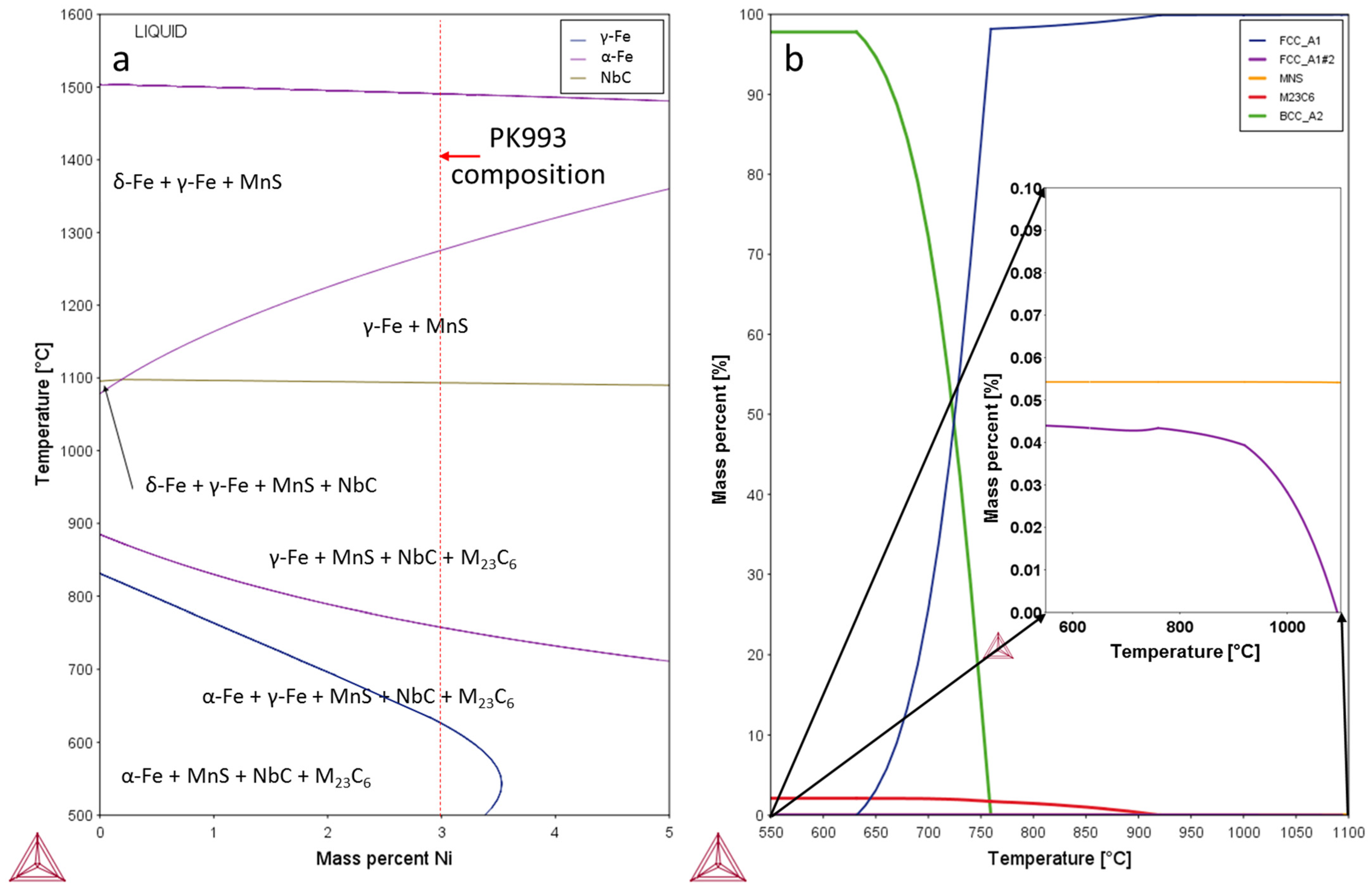
3.1. Thermodynamic Modelling
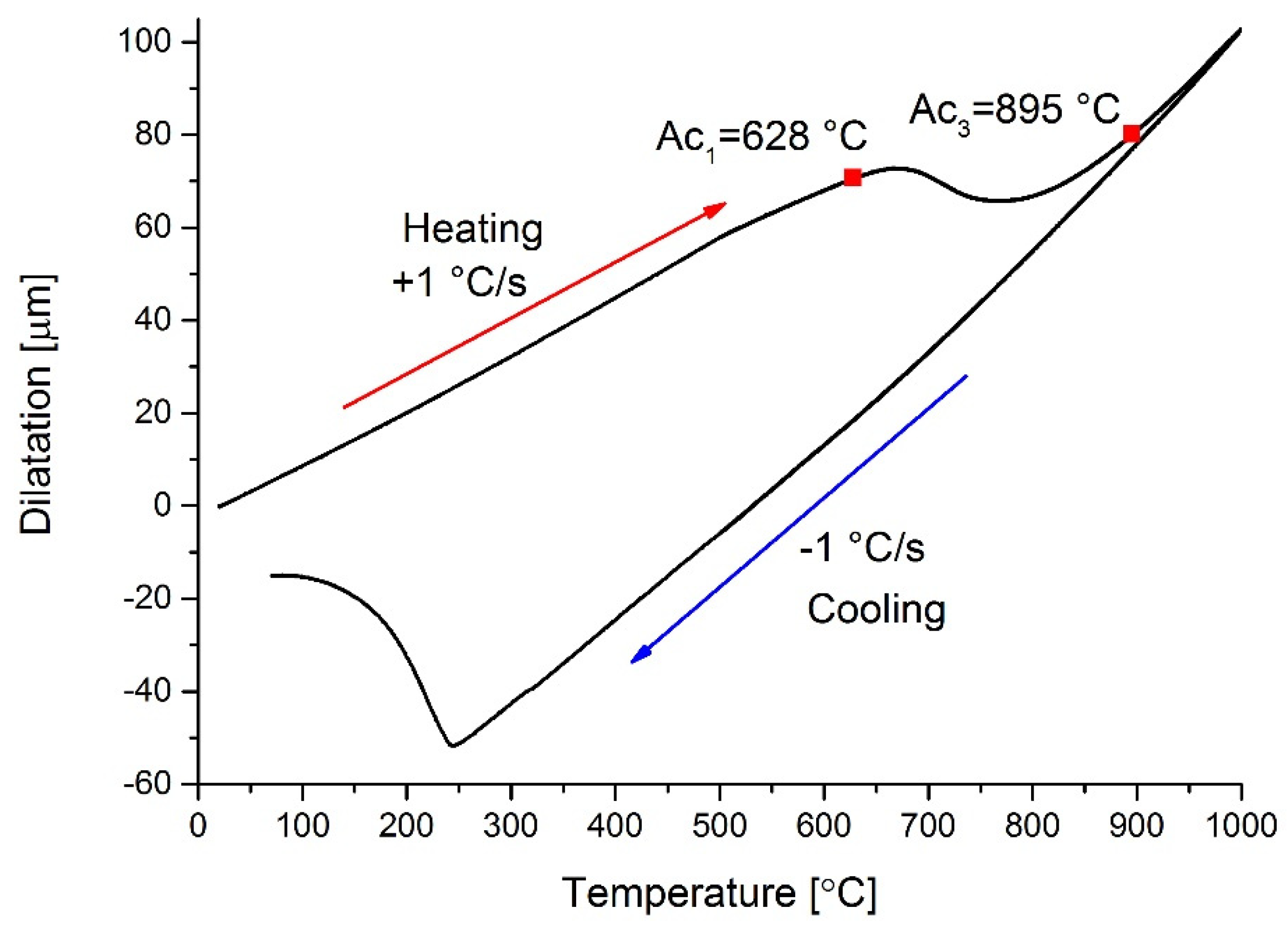
The ThermoCalc analysis (Figure 1b) showed that the Ae1 and Ae3 temperatures are 625 and 758 °C, respectively. Full austenitisation temperature was determined to be 920 °C. The quasi binary phase diagram with the variation of the Ni in Figure 1a shows that both Ae1 and Ae3 points are lowered with the increase of Ni. Therefore, the intercritical annealing temperatures were chosen at 740, 760, 780 and 800 °C. The equilibrium amount of austenite and its composition according to ThermoCalc is given in Table 3. The austenite that was formed at intercritical annealing contains less carbon, chromium, molybdenum and vanadium due to the stability of M23C6 carbides. MC-type carbides, mainly NbC and MnS, are also present at the austenitization temperature, but the MC carbide content is below 0.05%, while MnS does not play a significant role at such low S values. M23C6-type carbides are typical for steels with high Cr and low to medium C contents, especially martensitic stainless steels like AISI410 and AISI420 [34,35].

3.2. Dilatometry

The dilatometric analysis showed that the transformation temperatures Ac1 and Ac3 are 628 and 895 °C, respectively (Figure 2). During the intercritical annealing, partial austenitization occurred during the two hour holding and martensite formation upon cooling. However, the change in length during the isothermal holding was larger for the lower intercritical annealing temperatures (Figure 3). The cut-off slopes at the annealing temperatures indicate the continuation of the transformation to austenite, this means that at 740 °C most of the transformation occurred during the annealing. The martensite start temperatures were higher for the lower intercritical annealing temperatures, the highest were 345 °C for 740 °C and the lowest were 304 °C for 800 °C (Figure 4), while the martensite start temperature for the initial quenching from 1000 °C was 240 °C.

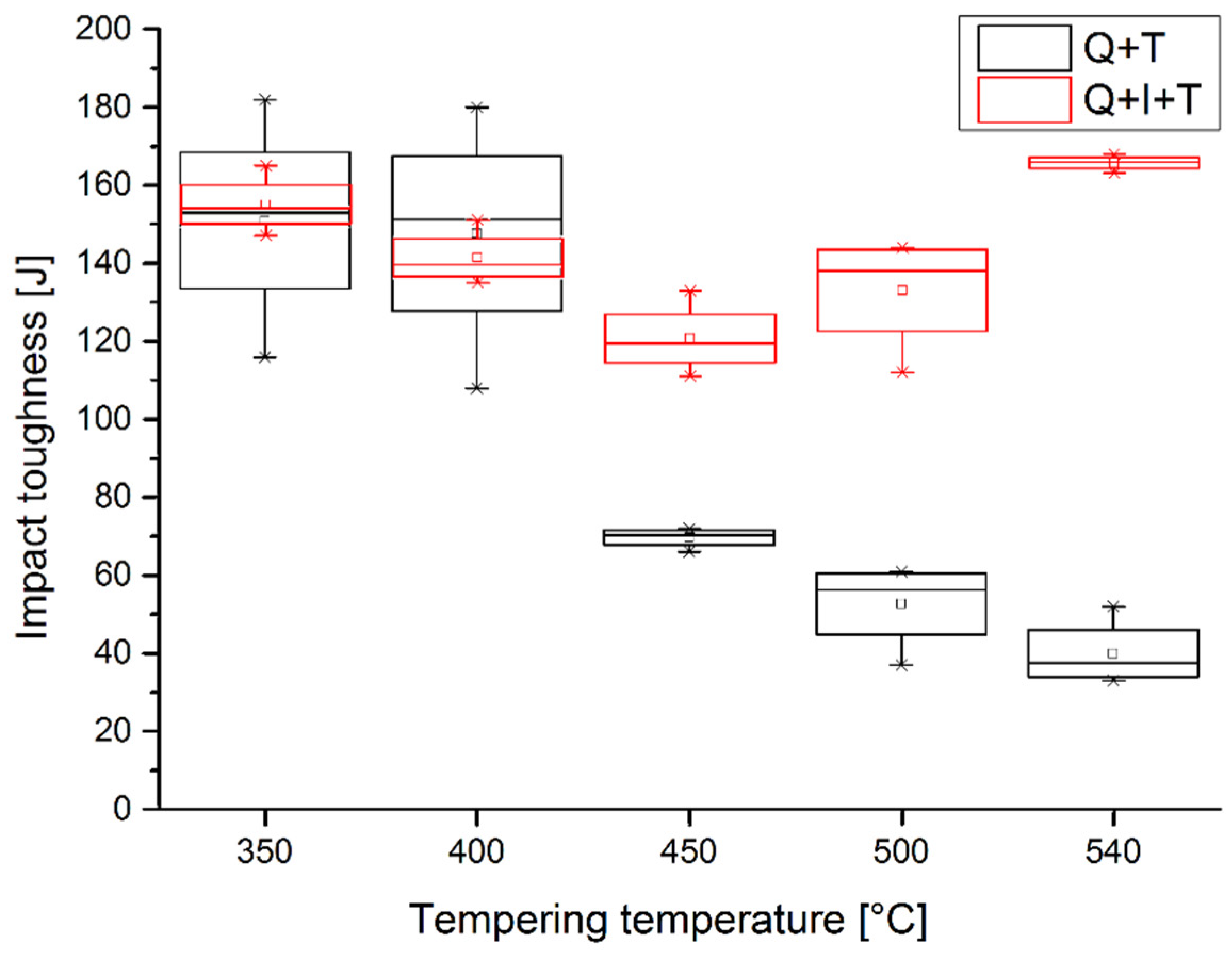
3.3. Mechanical Properties

The tensile strength and hardness measurements are presented Figure 5 and Table 4. The tensile tests showed a substantial drop in both yield and ultimate tensile strength for about 100 MPa in Rp0.2 and 300 MPa in Rm when intercritical annealing was conducted. The hardness values also show significantly lower values.
The results of Charpy impact toughness are very scattered after the conventional Q + T treatment. Except for the steel tempered at 450 and 500 °C, the conventional Q + T treatment show a substantially larger deviation than modified Q + I + T treatment. Q + I + T samples tempered at 450, 500 and 540 °C have also a higher impact toughness than conventional heat treatment. The results are presented in Table 5.
A small amount of retained austenite was found in the Q + T samples (0.5 vol%), while there was no retained austenite in the intercritically annealed samples. The increased nickel content can lead to retained austenite formation in martensitic stainless steels [36]. The light optical microscopy did not reveal any prior-austenite grain refinement during the intercritical annealing, the prior austenite grains were estimated to be between 5 and 6 for all samples (ASTM standard).

3.4. Microstructure

The micrographs reveal a martensitic structure in all samples; however, the martensitic structure is finer in the intercritically annealed samples. A comparison between the Q + T and Q + I + T samples annealed at 540 °C is shown in Figure 6.
The scanning electron microscopy of the Q + T and Q + I + T samples revealed a difference in the carbide precipitation and numerous smaller martensite lath packets in the intercritically annealed samples (Figure 7). The tempering carbides are elongated and perpendicular to each other in the Q + T samples, while they are smaller and less elongated in the Q + I + T samples (Figure 7). The Q + T samples also have a thin continuous carbide film along the prior-austenite grain boundaries, while the carbides have coarsened and grown larger in the intercritically annealed samples (Figure 7). Furthermore, during intercritical annealing, carbide precipitation also occurred along the martensite laths; however, these carbides are coarser than the tempering carbides and are stable at 760 °C. The sample that was not intercritically annealed, only quenched from 1000 °C, revealed that a thin carbide film forms along the prior-austenite grain boundaries during the quenching; however, no carbides were observed within martensite laths (Figure 8). Additionally, local intergranular corrosion appeared on the grain boundaries during etching (Figure 8a).
Scanning electron microscopy of the dilatometer intercritically annealed samples revealed that differently shaped carbides form along the martensite laths/austenite nucleation sites. Thin elongated carbides form along these former martensite laths during the annealing at 740 °C, while they start to coarsen and form stringers at 760 °C (Figure 9). A further increase of the annealing temperature causes an increased formation of stringer carbides along the former laths and round carbides on the prior austenite grain boundaries. At the highest intercritical annealing temperatures, i.e., 780 °C and 800 °C, it can be seen that martensite habitus start to disappear locally and equiaxed ferrite grains can be observed.

4. Discussion

In the present research, the effect of intercritical annealing of PK993/1CH13N3 martensitic stainless steel was studied. The thermodynamic analysis showed that Ae1 (625 °C) and Ae3 (758 °C) transformation points have been lowered, due to the increased Ni content. The Ac1 transformation point during slow non-equilibrium heating (1 °C/s) is 628 °C, which is in very good agreement with the calculated value. In contrast the measured Ac3 value is much higher (895 °C) than the calculated value. The presence of equiaxed ferrite in the 800 °C sample (Figure 9) proves that the Ae3 temperature is too low. Nonetheless, this means that the ferrite content during intercitical annealing is very low, close to zero, and cannot be detected by XRD. The share of austenite in the intercritical α + γ region starts to increase rapidly after about 660 °C (Figure 1b). The first intercritically annealed sample at 740 °C therefore contains the least amount of austenite and subsequently the least carbon in the austenite. The continuous transformation of ferrite to austenite during annealing is visible in Figure 3, especially when annealing at 740 °C, and is expressed by the cut-off peak. The majority of the transformation to austenite occurred at the annealing temperature at 740 °C, while the transformation to austenite was practically already over when annealing at 800 °C. This is visible from the vertical lines on the graph in Figure 3. The large difference in dilatation during annealing at 740 °C is due to the bigger relative difference between the BCC and FCC volumes at lower temperatures. The increasing annealing temperature has a significant effect on the solubility of carbon in austenite, this is evident in the different martensite start temperatures. The lowest Ms was 345 °C for 740 °C, it gradually increased to 304 °C for 800 °C, while the samples quenched from 1000 °C had Ms at 240 °C (Figure 3).
After quenching from 1000 °C in oil, the samples were additionally intercritically annealed at 760 °C, which was followed by tempering. The microstructure and mechanical properties (Rp, Rm, hardness and Charpy impact toughness) were compared to the conventional Q + T heat-treated samples.
The results of intercritical annealing between Ac1 and Ac3 show that partial, i.e., second, austenitization, which is accompanied by a slight partitioning of alloying elements [37]. The austenite formation and subsequent quenching refined the microstructure of the steel; however, this was not expressed in noticeable prior austenite grain size reduction but in the formation of a lamellar morphology, which consists of a tempered martensite matrix with the newly formed martensite lamellas upon subsequent cooling of the reverted austenite from the intercritical temperatures. The martensite itself consists of smaller laths. Microstructure analyses also showed that intercritically annealed samples have smaller and more homogeneously distributed carbides without a thin carbide film along prior austenite grain boundaries that was observed in the conventional Q + T heat-treated samples.
Nevertheless, the finer martensite morphology was found to have a profound effect on the homogeneity of mechanical properties, mainly on the scattering of the impact toughness values which were substantially lower (Figure 10) than in the case of Q + T samples. Moreover, the values of Charpy impact toughness of Q + I + T samples were higher in three samples (450, 500 and 540 °C) and approximately the same in two (350 and 400 °C). This improvement in Charpy impact toughness results can be attributed to intercritical annealing, which, first dissolved and second, prevented the re-formation of thin carbide layers on the prior austenite grains during tempering. Namely, thin carbide layers along PAGB have a detrimental effect on toughness and they are also responsible for the scattering of the impact toughness values in the quenched and tempered samples. However, Chakraborty et al. have attributed the 500–570 °C embrittlement to the formation of Fe-rich carbides, which were not analysed in this study, but would also be affected by the intercritical annealing [35].
The highest impact toughness values for the Q + T samples were obtained at the lowest tempering temperatures, i.e., 350 and 400 °C, while the lower impact toughness values were obtained at higher tempering temperatures 450–540 °C. This indicates that the thickening of the carbide film during tempering has the greatest effect on the lowering of the toughness. However, even at high impact toughness values (150 J), the standard deviations for the Q + T are around 30 J, while the Q + I + T standard deviations at such impact toughness values are below 10 J (Figure 10). It is most noteworthy that this results in unreliable impact toughness values throughout the material.
On the other hand, the tensile strength and hardness in the intercritically annealed samples are lower in comparison to the Q + T sample. This is due to the formation of the new martensite that contains less carbon, which is bonded to stable M23C6 carbides.
The highest hardness values obtained in the Q + I + T were 33 HRC, while the Q + T gave values up to 42 HRC. Since the requirements for hardness were 32-37 HRC, only one heat treatment in Q + T (540 °C) and three in the Q + I + T (350, 400 and 450 °C) qualified. The impact toughness criteria above 40 J then further eliminated Q + T at 540 °C. The Q + I + T samples have a weaker response to tempering than the Q + T samples, in terms of impact toughness and hardness, due to the lower value of carbon in the martensite, that forms after intercritical annealing.
The downside of the intercitical annealing is the fact that austenite contains less carbon, namely, at an intercritical temperature of 760 °C that is only 0.022% C and therefore it possesses lower hardness after quenching. With the increasing intercritical annealing temperature, Ostwald ripening occurs; however, at 780 °C and more pronounced at 800 °C martensite habitus start to disappear locally and equiaxed ferrite crystal grains are formed in the microstructure. This is due to the high temperatures and the thermodynamic stability of both austenite and ferrite. The driving force for the recrystallization prevails over the pinning action of carbide particles on the low-angle lath boundaries that results in lath replacement with more equiaxed ferrite grain boundaries and thus, some carbide stringers can be observed within polygonal ferrite crystal grains.
Due to the softening effect of the equiaxed ferrite, the heat treatments with intercritical annealing at 780 °C and above were excluded from further experiments. On the other hand, the intercritical temperature of 740 °C was estimated to have insufficient austenitisation that resulted in an insufficient decomposition of the carbide film. Carbide precipitation along the prior austenite grain boundaries and martensite laths is typical for high temperature tempering [38].
In all the Q + I + T samples retained, austenite was not detected. Martensite start temperature is higher in the case of intecritically annealed samples and increases with the lowering of intercritical temperatures. This is due to lower concentrations of carbon and chromium, which are bonded in stable chromium-based carbides (M23C6) in second austenite during partial austenitisation between Ac1 and Ac3. However, with increasing temperature the carbides slowly dissolve in austenite. Therefore, the sample that was quenched from 1000 °C has the lowest Ms.
The results of the mechanical testing have shown that the intercritical quenching decomposes the deleterious thin carbide film that forms during quenching from 1000 °C, but at the cost of lower tensile strength and hardness.
We can also predict that the presence of the carbide film increases the chance of intergranular corrosion, as indicated by pronounced boundary etching on Figure 8a. Therefore, the Q + I + T heat treatment could improve the corrosion resistance. However, additional analysis and experiments have to be conducted.

5. Conclusions

In the present work the effect of intercritical annealing on the mechanical properties and evolution of the microstructure of PK993/1CH13N3 martensitic stainless steel was studied.
The conventional (Q + T) heat treatment results in a formation of a carbide film on the prior austenite grain boundaries that has a detrimental effect on the impact toughness and causes a large deviation in its values. However, the resulting hardness and tensile strength values are high and do not deviate as much.
The modified (Q + I + T) heat treatment was developed to counter the detrimental effect of the carbide film. During the modified treatment the film is dissolved and its formation during tempering is prevented. The new heat treatment also refines the martensitic microstructure, which shows a lamellar morphology which consists of tempered martensite and newly formed martensite. The microstructure is more homogeneous and has a finer carbide distribution.
The modified heat treatment resulted in higher and less scattered impact toughness values. The drawback is in the lower hardness and tensile strengths, due to a lower carbon concentration in new martensite. No retained austenite was detected.

Author Contributions

Conceptualization, J.B., A.N. and B.Š.; methodology, M.Č.; software, J.B.; validation, M.Č., B.Š. and A.N.; formal analysis, J.B. and A.N.; investigation, A.N., B.Š. and M.Č.; resources, B.Š.; data curation, M.Č.; writing—original draft preparation, J.B., A.N. and M.Č.; writing—review and editing, J.B. and A.N.; visualization, B.Š.; supervision, A.N.; project administration, J.B. and B.Š.; funding acquisition, J.B. All authors have read and agreed to the published version of the manuscript.

Funding

The APC was funded by the Slovenian Research Agency ARRS program P2-0050 (C).

Conflicts of Interest

The authors declare no conflict of interest.

References

  1. Dalmau, A.; Richard, C.; Igual-Muñoz, A. Degradation mechanisms in martensitic stainless steels: Wear, corrosion and tribocorrosion appraisal. Tribol. Int. 2018, 121, 167–179. [Google Scholar] [CrossRef]
  2. Lo, K.H.; Shek, C.H.; Lai, J.K.L. Recent developments in stainless steels. Mater. Sci. Eng. R Rep. 2009, 65, 39–104. [Google Scholar] [CrossRef]
  3. Talha, M.; Behera, C.K.; Sinha, O.P. A review on nickel-free nitrogen containing austenitic stainless steels for biomedical applications. Mater. Sci. Eng. C 2013, 33, 3563–3575. [Google Scholar] [CrossRef]
  4. Baddoo, N.R. Stainless steel in construction: A review of research, applications, challenges and opportunities. J. Constr. Steel Res. 2008, 64, 1199–1206. [Google Scholar] [CrossRef]
  5. Gupta, R.K.; Birbilis, N. The influence of nanocrystalline structure and processing route on corrosion of stainless steel: A review. Corros. Sci. 2015, 92, 1–15. [Google Scholar] [CrossRef]
  6. Alam, M.K.; Mehdi, M.; Urbanic, R.J.; Edrisy, A. Mechanical behavior of additive manufactured AISI 420 martensitic stainless steel. Mater. Sci. Eng. A 2020, 773, 138815. [Google Scholar] [CrossRef]
  7. Koležnik, M.; Burja, J.; Šetina Batič, B.; Nagode, A.; Medved, J. De-oxidation of Pk942 steel with Ti and Zr. Mater. Tehnol. 2017, 51, 1031–1036. [Google Scholar] [CrossRef]
  8. Geng, H.; Wu, X.; Wang, H.; Min, Y. Effects of copper content on the machinability and corrosion resistance of martensitic stainless steel. J. Mater. Sci. 2008, 43, 83–87. [Google Scholar] [CrossRef]
  9. Al Dawood, M.; El Mahallawi, I.S.; Abd El Azim, M.E.; El Koussy, M.R. Thermal aging of 16Cr-5Ni-1Mo stainless steel Part 2—Mechanical property characterisation. Mater. Sci. Technol. 2004, 20, 370–374. [Google Scholar] [CrossRef]
  10. Garcia de Andres, C.; Alvarez, L.F.; Lopez, V.; Jimenez, J.A. Effects of carbide-forming elements on the response to thermal treatment of the X45Cr13 martensitic stainless steel. Ann. Oper. Res. 2000, 97, 131–141. [Google Scholar] [CrossRef]
  11. Al Dawood, M.; El Mahallawi, I.S.; Abd El Azim, M.E.; El Koussy, M.R. Thermal aging of 16Cr-5Ni-1Mo stainless steel Part 1—Microstructural analysis. Mater. Sci. Technol. 2004, 20, 363–369. [Google Scholar] [CrossRef]
  12. Marshall, A.W.; Farrar, J.C.M. Welding of Ferritic and martensitic 11–14% Cr STEELS—Part 1. Weld. Res. Abroad 2001, 45, 32–55. [Google Scholar]
  13. Marcuci, J.R.J.; Camilo, C.C.; Di Lorenzo, P.L.; Domingos de Almeida Rollo, J.M. Mathematical modeling of dilatometric behavior of 420A and 440C martensitic stainless steels used in surgical tools. Rev. Bras. Eng. Biomed. 2013, 29, 25–31. [Google Scholar] [CrossRef] [Green Version]
  14. Prieto, G.; Tuckart, W.R.; Ipiña, J.E.P. Influence of a cryogenic treatment on the fracture toughness of an AISI 420 martensitic stainless steel. Mater. Tehnol. 2017, 51, 591–596. [Google Scholar] [CrossRef]
  15. Zhang, S.; Wang, P.; Li, D.; Li, Y. Investigation of the evolution of retained austenite in Fe-13%Cr-4%Ni martensitic stainless steel during intercritical tempering. Mater. Des. 2015, 84, 385–394. [Google Scholar] [CrossRef]
  16. Ma, X.P.; Wang, L.J.; Qin, B.; Liu, C.M.; Subramanian, S.V. Effect of N on microstructure and mechanical properties of 16Cr5Ni1Mo martensitic stainless steel. Mater. Des. 2012, 34, 74–81. [Google Scholar] [CrossRef]
  17. Niessen, F.; Grumsen, F.B.; Hald, J.; Somers, M.A.J. Formation and stabilization of reverted austenite in supermartensitic stainless steel. Metall. Res. Technol. 2018, 115, 402. [Google Scholar] [CrossRef]
  18. Lumney, T.; Morton, I. Nanostructure Control of Materials. In Nanoengineering of Metallic Materials; CRC Press: Boca Raton, FL, USA, 2006. [Google Scholar] [CrossRef]
  19. Naghizadeh, M.; Mirzadeh, H. Effects of Grain Size on Mechanical Properties and Work-Hardening Behavior of AISI 304 Austenitic Stainless Steel. Steel Res. Int. 2019, 90, 1900153. [Google Scholar] [CrossRef]
  20. Bilmes, P.D.; Solari, M.; Llorente, C.L. Characteristics and effects of austenite resulting from tempering of 13Cr-NiMo martensitic steel weld metals. Mater. Charact. 2001, 46, 285–296. [Google Scholar] [CrossRef]
  21. Karlsen, M.; Hjelen, J.; Grong, Ø.; Rørvik, G.; Chiron, R.; Schubert, U.; Nilsen, E. SEM/EBSD based in situ studies of deformation induced phase transformations in supermartensitic stainless steels. Mater. Sci. Technol. 2008, 24, 64–72. [Google Scholar] [CrossRef]
  22. LeBrun, T.; Nakamoto, T.; Horikawa, K.; Kobayashi, H. Effect of retained austenite on subsequent thermal processing and resultant mechanical properties of selective laser melted 17-4 PH stainless steel. Mater. Des. 2015, 81, 44–53. [Google Scholar] [CrossRef]
  23. Guo, Z.; Sha, W.; Wilson, E.A.; Grey, R.W. Improving Toughness of PH13-8 Stainless Steel through Intercritical Annealing. ISIJ Int. 2003, 43, 1622–1629. [Google Scholar] [CrossRef]
  24. Iwabuchi, Y.; Kobayashi, I.; Ohmori, M.; Kikuchi, M. Precipitation and decomposition behaviors of reverted austenite in 13Cr-4Ni stainless steel. Nippon Kinzoku Gakkaishi/J. Jpn. Inst. Met. 1994, 58, 411–417. [Google Scholar] [CrossRef] [Green Version]
  25. Liu, Y.R.; Ye, D.; Yong, Q.L.; Su, J.; Zhao, K.Y.; Jiang, W. Effect of heat treatment on microstructure and property of Cr13 super martensitic stainless steel. J. Iron Steel Res. Int. 2011, 18, 60–66. [Google Scholar] [CrossRef]
  26. Nakada, N.; Tsuchiyama, T.; Takaki, S.; Miyano, N. Temperature dependence of austenite nucleation behavior from lath martensite. ISIJ Int. 2011, 51, 299–304. [Google Scholar] [CrossRef] [Green Version]
  27. Da Silva, G.F.; Tavares, S.S.M.; Pardal, J.M.; Silva, M.R.; De Abreu, H.F.G. Influence of heat treatments on toughness and sensitization of a Ti-alloyed supermartensitic stainless steel. J. Mater. Sci. 2011, 46, 7737–7744. [Google Scholar] [CrossRef]
  28. Bojack, A.; Zhao, L.; Morris, P.F.; Sietsma, J. In-situ determination of austenite and martensite formation in 13Cr6Ni2Mo supermartensitic stainless steel. Mater. Charact. 2012, 71, 77–86. [Google Scholar] [CrossRef]
  29. Leem, D.S.; Lee, Y.D.; Jun, J.H.; Choi, C.S. Amount of retained austenite at room temperature after reverse transformation of martensite to austenite in an Fe-13%Cr-7%Ni-3%Si martensitic stainless steel. Scr. Mater. 2001, 45, 767–772. [Google Scholar] [CrossRef]
  30. Martinek, P.; Hradil, D.; Malina, J. Selection of Materials for Components of Linearstepper Motors for Nuclear Power Plants. Int. J. Mech. Prod. Eng. 2019, 7, 38–43. [Google Scholar]
  31. Godbole, K.; Das, C.R.; Joardar, J.; Albert, S.K.; Ramji, M.; Panigrahi, B.B. Toughening of AISI 410 Stainless Steel Through Quenching and Partitioning and Effect of Prolonged Aging on Microstructure and Mechanical Properties. Metall. Mater. Trans. A Phys. Metall. Mater. Sci. 2020, 51, 3377–3383. [Google Scholar] [CrossRef]
  32. Escobar, J.D.; Oliveira, J.P.; Salvador, C.A.F.; Tschiptschin, A.P.; Mei, P.R.; Ramirez, A.J. Double-step inter-critical tempering of a supermartensitic stainless steel: Evolution of hardness, microstructure and elemental partitioning. Mater. Charact. 2019, 158, 109994. [Google Scholar] [CrossRef]
  33. Abbasi-Khazaei, B.; Mollaahmadi, A. Rapid Tempering of Martensitic Stainless Steel AISI420: Microstructure, Mechanical and Corrosion Properties. J. Mater. Eng. Perform. 2017, 26, 1626–1633. [Google Scholar] [CrossRef]
  34. Žužek, B.; Vodopivec, F.; Jenko, M.; Podgornik, B. Effect of creep strain on creep rate in the temperature range 550–640 °C. Mater. Tehnol. 2014, 48, 545–548. [Google Scholar]
  35. Kaňa, V.; Krutiš, V.; Bořil, P.; Záděra, A.; Rimko, M. Influence of Heat Treatment and Nickel Content on the Properties of the GX4CrNi13-4 Steel. Arch. Metall. Mater. 2021, 66, 37–41. [Google Scholar] [CrossRef]
  36. Burja, J.; Šuler, B.; Nagode, A. Effect of ageing temperature on reverse austenite content in AISI 630 stainless steel. Materwiss. Werksttech. 2019, 50, 405–411. [Google Scholar] [CrossRef]
  37. Chakraborty, G.; Das, C.R.; Albert, S.K.; Bhaduri, A.K.; Paul, V.T.; Panneerselvam, G.; Dasgupta, A. Study on tempering behaviour of AISI 410 stainless steel. Mater. Charact. 2015, 100, 81–87. [Google Scholar] [CrossRef]
  38. Li, J.; Zhang, C.; Liu, Y. Influence of carbides on the high-temperature tempered martensite embrittlement of martensitic heat-resistant steels. Mater. Sci. Eng. A 2016, 670, 256–263. [Google Scholar] [CrossRef]
Figure 1. ThermoCalc thermodynamic calculations, (a) quasi binary Ni phase diagram with marked PK993 chemical composition, (b) thermodynamically stable phases in PK993, calculated by ThermoCalc.
Metals 11 00392 g001
Figure 2. Dilatometry, Ac1 and Ac3 point determination.
Metals 11 00392 g002
Figure 3. Dilatation at different intercritical annealing temperatures.
Metals 11 00392 g003
Figure 4. Dilatation curves upon quenching from different intercritical annealing temperatures with martensite start (Ms) temperatures.
Metals 11 00392 g004
Figure 5. Yield strength (Rp0.2), tensile strength (Rm) and elongation (A) of Q + T and Q + I + T specimens at different annealing temperatures.
Metals 11 00392 g005
Figure 6. Optical micrographs of the Q + T (1000 + 540 °C) and Q + I + T (1000 + 760 + 540 °C) samples.
Metals 11 00392 g006aMetals 11 00392 g006b
Figure 7. SEM images of (a), (c) Q + T (1000 + 450 °C) and (b), (d) Q + I + T (1000 + 760 + 450 °C) samples; SEI.
Metals 11 00392 g007
Figure 8. A thin carbide film on the grain boundaries in the sample quenched from 1000 °C (a) lower magnification, (b) higher magnification of the carbide film; SEI.
Metals 11 00392 g008aMetals 11 00392 g008b
Figure 9. Microstructures of samples annealed at different intercritical temperatures; SEI. (a) 740 °C (b) 760 °C (c) 780 °C (d) 800 °C.
Metals 11 00392 g009aMetals 11 00392 g009b
Figure 10. Charpy impact toughness for Q + T and Q + I + T samples at different tempering temperatures.
Metals 11 00392 g010
Table 1. Chemical composition of PK993.
CSiMnPSCrNiMoVCu
0.120.240.40.0120.00212.92.930.140.030.09
WAlBTiNbCoH (ppm)AsSbSn
0.040.0090.000660.0010.0040.024.50.0060.0040.007
Table 2. Experimental setup.
No.Tγ 1 (°C)TI 2 (°C)TA 3 (°C)Sample Type
11000-3503xtensile, 3xCharpy
21000-4003xtensile, 3xCharpy
31000-4503xtensile, 3xCharpy
41000-5003xtensile, 3xCharpy
51000-5403xtensile, 3xCharpy
610007603503xtensile, 3xCharpy
710007604003xtensile, 3xCharpy
810007604503xtensile, 3xCharpy
910007605003xtensile, 3xCharpy
1010007605403xtensile, 3xCharpy
111000740-dilatometer
121000760-dilatometer
131000780-dilatometer
141000800-dilatometer
151000--dilatometer
1 Tγ is austenitization temperature, 2 TI is intercritical temperature (Ac1 < TI < Ac3); 3 TA is annealing temperature.
Table 3. Amount of austenite (wt%) and its composition (wt%) at intercritical annealing temperatures calculated with ThermoCalc.
T/°Cγ FeCSiMnCrNiMoVAl
100010083.230.120.240.412.92.930.140.0300.009
80098.4584.180.0360.240.4012.072.970.070.0200.009
78098.3284.280.0290.240.4011.982.980.060.0190.009
76098.2184.360.0220.240.4011.912.980.050.0180.009
74071.0184.190.0180.240.4811.513.500.040.0140.007
Table 4. Hardness measurements.
Tempering (°C)Q + TQ + I + T
HBHRCHVHBHRCHV
350410 ± 1041.1 ± 1.1418 ± 12336 ± 933.1 ± 1.3351 ± 12
400410 ± 842.0 ± 0.5420 ± 8333 ± 832.8 ± 0.9344 ± 10
450422 ± 842.7 ± 0.7433 ± 10335 ± 533.7 ± 0.2346 ± 5
500418 ± 1041.8 ± 1421 ± 10306 ± 330.8 ± 0.5318 ± 4
540324 ± 333.4 ± 0.3333 ± 5280 ± 225.7 ± 0.1296 ± 3
Table 5. Charpy impact toughness.
Tempering (°C)Q + TQ + I + T
123AverageStandard Deviation123AverageSt. Dev
35011618215515133.21531471651559.2
400155180108147.736.6151138135141.38.5
45066727169.73.2133118111120.711.2
50060376152.713.614314411213318.2
5403335524010.4163166168165.72.5
Publisher’s Note: MDPI stays neutral with regard to jurisdictional claims in published maps and institutional affiliations.

