Article

Numerical Evaluation of Prequalified End-Plate Connections Used in a Framed Steel Industrial Structure

Civil Engineering School, Pontificia Universidad Católica de Valparaíso, Valparaíso 2340000, Chile
*
Author to whom correspondence should be addressed.
Metals 2021, 11(2), 243; https://doi.org/10.3390/met11020243
Submission received: 10 December 2020 / Revised: 22 January 2021 / Accepted: 28 January 2021 / Published: 1 February 2021

Abstract

:
The design of end-plate connections for steel structures is more loosely specified in Chilean regulations than in American regulations. Nevertheless, eight-bolt extended stiffened (8ES) end-plate connections have not derived benefit from extensive past research, and therefore, their normative recommendations are quite constraining. In this study, both the prequalification and qualification limits are evaluated, and the linear and nonlinear analyses of a connection from a case study focused on a typical industrial structure, characterized by its reduced dimensions, are carried out. For the design of the connection, a spreadsheet was developed based on AISC 358. The nonlinear analysis was modeled using the finite element method, and it is confirmed that the normative recommendations restrict the design in a very conservative way, resulting in oversizing. Finally, a new optimized connection configuration is proposed and analyzed without stiffeners.

1. Introduction

End-plate connections (EPCs) are currently one of the most recurrent elements in the design of steel buildings due to their low economic cost, ease of manufacture and implementation, and good performance [1]; therefore, EPCs are a suitable alternative to fully welded joints when moment-resistant connections are required [2]. The connection is usually subjected to a combination of vertical shear loads, an axial load, and a bending moment on the beam [3]. The influence of stresses and the strain distribution in this type of connection provided significant evidence for the design process [2].
During a seismic event, part of the energy is dissipated through inelastic deformations of the components of the steel moment frame. The plastic effects can be generated through a plastic hinge formed in the beam or column, by yielding of the connecting members, or by shear in the panel zone [4]. The panel zone is geometrically defined as the area product of the intersection between the flanges of the column and the projection of the flanges of the beam(s), thus comprising a quadrilateral part of the web of the column. This zone is characterized by high flexibility and can be affected by large stress demands, which can lead to excessive deformations in the case of an inappropriate design [5]. Universally and normatively, it is sought that plasticity is produced in the beam, and the yielding of the connecting elements and the column is avoided, the latter being the least desired effect. Nonetheless, laboratory tests have shown that it is very difficult to obtain discrete locations of the plastic hinge and that, coupled with it, no yielding is reached in the panel zone [4].
Regarding the prying forces, in the case of cyclic loads, keeping in mind the strong column-weak beam design criteria, the connection is forced as much as the column to remain elastic. Consequently, it is intended that the end plate and the column wings exhibit typical thick-plate behavior. In this way, elastic behavior is ensured, and the bolts are not subjected to prying forces [6].
After the Northridge (Mw = 6.7, 1994) and Hyogo-ken, Nanbu (Mw = 6.9, 1995) earthquakes, American regulations led to a requirement for the use of prequalified connections in modern structural designs of special moment resisting frames (SMRFs) without bracing steel [5]. Currently, such connections are compiled according to nine different connections in AISC 358: Prequalified Connections for Special and Intermediate Moment Steel Frames for Seismic Applications [7]. In general, the distribution of forces and displacements in the connections is much more complex than in the connected members [1] since the proposed design for AISC 358 prequalified connections implies the analysis and fulfilment of several requirements. Additionally, such requirements are subject to very high limits that force an oversized design to be what is real and practically needed.
In Chile, there are two national regulations regarding structural steel design: standards NCh 427/1: Construction Steel Structures-Part 1: Requirements for the Calculation of Steel Structures for Buildings [8] and NCh 2369: Seismic Design of Industrial Structures and Installations [9]. Both regulations present a very general scope regarding the design of connections, which leads to a wide variety of configurations and promotes oversizing in the design, as suggested by AISC 358. This view has led to the fact that, in Chilean professional practice, most engineers tend to avoid this task, delegating the design of the connections to the steel structure workshop.
The fabrication of steel connections by the steel structure workshop is carried out based on the ranges of parameters determined by habitual values in common practice as well as by the experience of the same, which can be very different from that of another steel structure workshop. Therefore, the connections are produced with large dimensions and highly resistant materials, which, from an optimization perspective, is an excessively conservative design.
On the other hand, depending on the type of connection, the expected stiffness, and the amount of these connections, the manufacturing costs can become an important part of the overall cost of the whole structure [1].
Over the past several years, the EPC literature has been overpopulated with investigations that use finite element methods (FEMs) to predict the behavior of this type of connection [10,11,12,13,14,15,16,17,18,19,20]. Despite this, the limitations found in several documents are similar and therefore universally recognizable. Within the main studies, the aim has been to establish the behavior of the end plate and not that of the bolts, including elementary models of the latter that do not satisfactorily predict their behavior. Second, the strength under monotonic and cyclic loads has been studied, generating moment-rotation relationships, with the subsequent classification of the connection. Third, most of the research has been concerned with small cross-sectional configurations of this type of connection (i.e., four-bolt extended type or flush type connections). The reason for this is that these configurations are more flexible than the larger ones, pointing towards the undoubted design of semi-rigid connections [4].
Among the relevant studies in the field, Hajjar, Dexter, Ojard, Ye, and Cotton [10] performed physical experiments such as multi-energy flow (MEF) analyses to re-evaluate the need for continuity and doubler plates for the reinforcement of the connection. The authors indicate that the practice of including these plates has repeatedly occurred, even when it was not always necessary. If necessary, excessive plate thicknesses were proposed for the demand and for the regulatory specifications. Likewise, the use of full penetration welds for the welds of the continuity plates to the flanges of the columns are typically employed when the usage of fillet welds would be more economical and sufficient.
In another work, Ismail, Fahmy, Khalifa, and Mohamed [2] carried out a parametric study using the FEM and concluded that for a four-bolt connection, the most influential parameters are the diameter of the bolts, the thickness of the end plate, the length of the continuity plate and the length of the stiffener. Furthermore, to increase the stiffness, rotational capacity and ultimate moment of a connection, it is more effective to increase the thickness of the end plate than to increase the diameter of the bolts, and these two parameters are specifically the most influential. However, an excessive increase in the thickness of the end plate could lead to brittle bolt failure and decrease the ductility of the connection. However, a considerable decrease in the thickness could generate a brittle failure of the plate itself, causing a prying effect on the bolts, as previously stated. On the other hand, despite having pointed out that the addition of end-plate stiffeners to an EPC is one of the most important factors in increasing the ultimate moment and stiffness capacity, the increase in stiffener length is the least significant. Finally, with regard to continuity plates, the presence of these plates increases by a very low magnitude at the ultimate moment of the connection but decreases the rotation capacity. In another work, Hoseinzadeh and Jahanian [21] investigated solutions, such as the use of short deep beams, to overcome the geometrical restrictions imposed by AISC 358 for prequalified connections. As a result, a rectangular opening in the web of a deep beam located at the midspan was proposed to lead the plastic hinge away from the column face. To stabilize the weakened area, different patterns of stiffeners around the opening were considered in the numerical models. The results showed that adding two horizontal stiffeners above and below the opening on both sides of the web, with lengths ranging between 1.2 and 1.5 times the opening length, significantly increased the ductility of the connection.
On the other hand, an important disadvantage is that the manufacture of continuity plates is expensive, and their placement can interfere with the weak axis of the connected column. Therefore, if the need to stiffen the column is marginal, then it is more economical to increase the size of the column section. If expressly necessary, increasing the effective length of the column flange (viz., the pitch between bolts) could eliminate the need for continuity plates [6].
It should be noted that Mashaly, El-Heweity, Abou-Elfath, and Osman [11] worked, in an extensive parametric study based on the FEM, with models subject to both monotonic and cyclical loading. According to this research, for an extended four-bolt EPC, the energy dissipation of the joints is closely related to the compactness ratio of the column as well as the grade of the steel. In contrast, the geometry of the connected beams has less influence, which could be neglected, according to this approach.
Research on the configuration of the eight-bolt extended stiffened (8ES) EPC has received less attention, with only two studies devoted to this sub-type connection. For example, Mays [4] used the FEM for the design of an 8ES EPC under cyclic load stress and thus was able to study the distributed load on the bolts as a result of the bending moments of the large magnitude produced. In another study, Zhou [1] also used the FEM to simulate the behavior of an 8ES EPC, focusing mainly on the respective moment curvature under monotonic and cyclic loads. Both studies implied the use of models that did not cover the full conformation of the beam-column connection under the cyclic load demand, leaving a gap in other areas of the investigation.
As previously stated, there are few studies that incorporate the specific 8-bolt configuration of the EPC. Furthermore, the design proposed by AISC 358 is quite complex, and the prequalification limits (PQLs) are characterized by being more excessive than necessary. In addition, it is found that Chilean standards are imprecise in relation to the design of steel connections and that the design of the latter is frequently delegated to steel structure workshop. According to these facts, this research will test and analyze the provisions set by the AISC 358 for the design, especially in reference to the PQLs, with the objective of proposing an optimization for the normative design. Consequently, the costs of the corresponding project are reduced, making better use of the capacities of the members and component elements of the EPCs, in accordance with the works that have sought to improve the safety of the connections resulting from the design [6,22,23,24,25,26].
The behavior of an 8ES EPC can be feasibly improved by simply modifying the properties of the connection, which is more feasible regarding cost than the modification of the cross sections of the connected members [1]. In consideration of the above, the present investigation is also focused on the specific evaluation of the behavior of the sections of connected profiles, the failure conditions of the end plate, and the possible occurrence of the prying effect on the bolts. This investigation is subjected to the PQLs that govern the design to test them with a theoretical case study. Additionally, the presence of continuity plates is analyzed to ratify or refute their recommendation for a design that characterizes them, even if necessary, according to regulatory limitations. In the same way, the doubler plate reinforcement is analyzed. Finally, it is determined how profitable or harmful the incursion of the elements of the connection into plastic behavior could be. All the results obtained are carefully observed, and it is necessary for the resulting connections to be submitted for laboratory tests to validate the numerical results obtained, following the recommendations found in various published works [27,28,29,30,31].
In the case of industrial and mining structures, it is important to consider atmospheric corrosion that can affect both structural members and connections. In this sense, the results of recent studies on the effects of corrosion in wrought iron elements [32,33] are important, in which the sensitivity of corroded structures to the action of dynamic forces of both seismic and wind origin is recognized. Although this aspect must be considered from the design stage of steel structures and passive energy dissipation systems [34], its application is mainly associated with surface preparation and coating procedures using protective paints against corrosion.

2. Assessment Methodology

The assessment methodology requires a representative model of a typical industrial structure. The selected structure is designed to meet the code-specific requirements to date in Chile, including those that establish seismic and wind loads. With the results obtained from the elastic analysis, the design of each of the structural members is performed, as well as the connections between them. From the resulting connections, a representative connection is selected, corresponding to the primary beam and column joint, which provides the most demanded configuration from the structural analysis.
Next, the selected connection is modeled using finite element components with their corresponding nonlinear constitutive relationships. All the load combinations resulting from the linear analysis used for the design are included in the model, which include the corresponding load factors considered by the load and resistance factor design (LRFD) code.
The nonlinear analysis pursues two main objectives. The first objective is to demonstrate that the capacity of the prequalified connection, including all the components considered in the design process, is adequate against the demand imposed by the loads. The second objective is to review some alternative configurations of the connection, which have been obtained by deleting some components required in the prequalification process and that according to the results of the previous objective, are not excessively demanded, verifying the capacity resulting from these alternative connections and comparing it with the demands imposed by the design loads.

3. Case Study

Because steel is the dominant material in Chile over a large part of the construction of structures and installations related to industrial activities, the type of structure to be modeled and analyzed seeks to represent a structural case usually seen in practice. The structure chosen represents the typical steel frame structures used in Chile in industrial and mining projects, and as can be seen, it is a structure of small dimensions in the sections of the beams and columns. At the same time, the case should be sufficiently exemplary, elementary, and representative, which is why a regular symmetrical structure was chosen with respect to the loads, resistance and stiffness, as well as the plan and height. Thus, a type of two-level open industrial platform was selected, as shown in Figure 1. The structure was modeled using Robot Structural Analysis Professional software [35], and it was subjected to the code’s prescribed dead, live, wind, and seismic loads. The structure is designed considering additional loads that correspond to a generic mechanical equipment bearing in the four points of the inner beams’ intersection at each level. The weight of the mechanical equipment located in both structural levels is 20 kN.
The resulting design sections are presented in Figure 2. From the analysis of this structure, the optimal members for each connection were chosen using A-36 steel members. The evaluation of the optimal members was carried out following the AISC 341 [36] and AISC 360 [37] design codes and considering the weight of each member and the fulfilment of the strong column-weak beam design criteria. Notably, this last type of analysis was supported by the use of a spreadsheet for the design of the 8ES EPC, which is presented in the following subsection.

Programming the Connection Design

The intricate design proposed by the AISC for prequalified connections, depending on the type, requires different varieties of verifications. For the case of an 8ES EPC, approximately 28 to 48 verifications are required, depending on whether column stiffeners are added (viz., continuity plates, double reinforcement plates, the types of welds to be used, and structural site conditions). On the other hand, several parameters influence more than one verification, so modifying any of these parameters to fulfil some requirements may cause the non-fulfilment of others.
Due to the two aforementioned reasons and because the best-known available software for connection design is not up to date in terms of current regulations, it was decided to generate a spreadsheet that automates the design of the 8ES EPC. The design follows the prescriptions of AISC 358 [7] as well as the specifications of AISC 341 [36] and AISC 360 [37]. This spreadsheet will be freely accessible and open source so that any civil engineer can adapt it according to his/her needs to facilitate the potential and scope of future research. Furthermore, this spreadsheet may be updated according to future design codes.

4. Design Assessment

The characteristic symmetry of the case study geometry allows the design of an 8ES EPC to be applicable for any of the four nodes of each level of the industrial platform, in the vertical plane in which a beam joins with a column does not present diagonals. Then, once the members to be used in the structure are specified, one of the first level nodes is chosen to carry out the design of the connection concerned subsequently.

Code’s Prescribed Design

Through tentative values, within certain logical limits such as prequalification, trial and error cycles were carried out until the optimal parameters were clarified.
The stipulated design exhibited low compliance around the PQL, with the column section being the only member that complied with all its parameters within the corresponding limits, as seen in Table 1, Table 2, Table 3 and Table 4.
The same node, previously chosen for the design of the 8ES EPC using the spreadsheet, was selected jointly by all the structural members concurrent to it for its subsequent import into the IDEA StatiCa Steel (ISS) software framework [38]. This software uses its own innovative analysis method, namely, the component-based finite element model (MEFBC), which mixes two popular methods among engineers worldwide, the FEM and the component method (CM).
The approach used in component-based finite elements allows the analysis of connections in both linear and non-linear ranges, modeling it as an interconnected set of items and components. For the case study, both the bolts and the end plates were modeled as an interconnected set of springs. In this way, the model allowed incorporating the constitutive law of the material of each component and once the analysis had been carried out, each of the components was verified independently.
The connection model was considered as a massless point in the structure, over which the combined and factored load cases were transferred according to the standards used in the design. The process of exporting these load cases from the structural analysis software to the connection analysis software was achieved through an interoperability link that works in BIM environments.
The constitutive law used in plate-type elements corresponds to an elastic-plastic model with hardening, to which appropriate values are assigned according to the quality of steel used. The plates were modeled using four-node shell elements. The nodes were located in the four corners of each element, having six degrees of freedom, three translational and three rotational. The plates were meshed according to their complexity and size, considering irregularities such as, for example, bolt holes. The material behavior was based on the von Mises yield criterion, appropriate for the plasticity of metals.
No less important is the incorporation of contact. The software considers three types of contact: surface-surface contact, edge-edge contact, and edge-surface contact. For its part, the welding of the joints was incorporated through the use of a rate-independent plasticity model formulated based on the von Mises yield criterion, while the bolts were modeled using nonlinear springs to represent their tensile behavior in tension, shear, and bearing. Once the node with its concurrent members, loads, and respective combinations was imported, certain conditions were required for modeling the connection. These conditions are as follows:
  • The basic regulation for checks was the AISC.
  • Both columns (up and low) were unified in a single column.
  • All the resulting Ultimate Limit State and Service Limit State combinations were used, including their upper and lower envelopes, in addition to Newmark’s combinations concerning seismic analysis directions.
Consequent on the scope of this research, five different models of the same 8ES EPC were developed:
  • Model 8ES EPC fully reinforced (CP-DP-ST)
  • Model 8ES EPC, only with continuity and stiffener plates (CP-ST)
  • Model 8ES EPC, only with doubler and stiffener plates (DP-ST)
  • Model 8ES EPC, only with stiffener plates (ST)
  • Model 8ES EPC, without any reinforcement plates (NP)
The first model consists of the design of the connection resulting from the spreadsheet, which includes continuity plates and doubler plate reinforcement, as outlined in Figure 3. Details of this resulting pre-qualified connection can be seen in Figure 4, in which the bracing was purposely omitted so that the details of the connection could be correctly appreciated. The second model consists of the connection resulting from the design but without doubler plate reinforcement, as shown in Figure 5a. The third model consists of the connection resulting from the design but without incorporating continuity plates, as presented in Figure 5b. The fourth model consists of the connection resulting from the design but without the inclusion of continuity plates as doubler plate reinforcement, as depicted in Figure 5c.
Based on the results achieved with the four previously presented models, which are discussed in more detail later, a new configuration was proposed for a fifth eight-bolt EPC model that presents most of the configuration characteristics of the 8ES EPC ST model. The difference lies in the fact that this new model does not have stiffeners and that the diameter of the bolts is 12 mm, which is less than the 16 mm of the four previous models. Furthermore, the end-plate thickness is 10 mm, and the total height is 504 mm, in contrast to the 18 mm thickness and 530 mm height of previous models. The new optimized EPC 8E (NP) model case is displayed in Figure 5d. It should be noted that for the 8ES EPC DP-ST model, the height of double reinforcement plates specified in the 8ES EPC CP-DP-ST model was replicated, ignoring what is specified in terms of its use without continuity plates in section E3.6e (a) of AISC 341 [36] to facilitate a comparison of the results.
On the other hand, within the modeling operations, the bolts were defined as supporting bolts with the interaction between tension and shear to transfer the shear force in the bolts. As its name suggests, this method combines inversely proportional tension forces with shear forces, resulting in the middle point between the bearing and friction methods, in addition to being less conservative than the latter.
Only two types of analysis are carried out for this research: stress/strain analysis (stress/strain analysis named ASS) and joint design resistance analysis (joint design resistance named DR). The first analysis involves evaluating the connection response based on the application of the input design load. The second analysis involves determining the maximum load achieved by the connection according to its response. The product of this analysis is the ratio of the maximum load divided by the design load. Both analyses are carried out in accordance with the regulations of the AISC-LRFD approach. Conversely, in both, the unbalanced forces resulting from the concurrence of forces in the connection are not considered since they only affect the supporting member (column) and not the component elements of the model. Since member design is not the focus of ISS software or this investigation, such a force condition is omitted [39].

5. Results Discussion

5.1. Graphic SSA Analysis Results

The SSA analysis type is carried out at 100% in relation to the application of the load combinations. An important feature of the results delivered by ISS are the various graphic representations of the MEFBC once subjected to analysis. Below, based on a notable similarity of results between models, some of those corresponding to the three most particular models are presented, that is, 8ES EPC CP-DP-ST, 8ES EPC ST, and EPC 8E NP.
In Figure 6, the equivalent stresses on each component of the connection are depicted through a color mapping scale. In Figure 7, the plastic deformations developed in each connection component are represented through color mapping. Figure 8 reflects one of the various possible local buckling modes, according to a specific combination of loads, with a color mapping circumscribed to the buckling zone.

5.2. Graphic DR Analysis Results

Regarding the DR type analysis, 100% of the load combinations were applied. Part of its results are presented graphically, relating percentage load vs. percentage strain for the most critical combination of loads for each model, as shown in Figure 9 and Figure 10. The maximum percentage values obtained for plate and weld strain are included in the graphs.

5.3. Global Results and Parametric Influence Analysis

Table 5, Table 6 and Table 7 present a summary of the maximum and minimum results of the EPS-type analyses as the DR of the three models.
First, to estimate the effect of each noncompliance of the PQL, the deficient percentages were calculated so that the value determined for the parameter concerned equalled its recommended values, as observed in Table 8, Table 9 and Table 10. This value comparison approach seeks to demonstrate the percentage of dimensional noncompliance of each parameter in relation to what is recommended.
Focusing on the percentages of dimensional noncompliance related to the lower bound PQLs, since they are practically the most important for this case, the beam section depth corresponded to 40.92% of the lower bound value. The section width corresponded to a 28.95% noncompliance, and the flange thickness corresponded to a 27.14% noncompliance. Therefore, the beam’s minimum noncompliance percentages can be summarized as an average of 32.34%, with a standard deviation of 6.11%. Notably, those parameters that meet within the ranges that define the PQL were not studied in this research, as they cannot be contrasted with their recommendation values, given that they only have one boundary value.
Regarding the bolt location parameters, the gauge had a minimum noncompliance percentage of 40.94% for p f i and 2.44% for p f o , both having the same dimension value. In the case of the 38.20% obtained for p b , it is not considered suitable to estimate an average for the noncompliance percentages since each of these properties is independent of the other. However, it was determined that the workable gauges, due to their high PQLs, comprise more significant savings in steel material and, therefore, are economical. With a 39.75% dimensional savings, the protected area implies significant savings by having a large prequalification recommendation.
In summary, for this EPC configuration, it is evident through the MEFBC results that the PQLs were high for both members and elements and excellent behavior is exhibited, with much smaller dimensions. For this case, if the member design is satisfactory but discordant with the relevant PQLs, maintaining their dimensions is the most convenient decision by committing a high material savings and preserving the safety of the structure.

5.4. Components Subject to Qualification Requirements

Utility percentage ( U ) values were computed through nonlinear analysis and through the design carried out following the design procedures of AISC 358, which are observed in Figure 11. In this figure, the U’s values are given to symbolize in an elemental way how much of the total capacity of the element is being used. From a holistic perspective, it is perceived that the elements designed according to the AISC 358 procedure are better used, reaching an average U of 89.82%, with a standard deviation of 8.32%, compared to those analyzed with the ISS software, with an average U of 21.30% and an 8.29% standard deviation.
Such findings can be explained by considering that the design proposed by AISC 358 is based on the results of elastic analysis; this is not the case with the analysis performed using ISS, which allows the possibility of yielding in the components. In addition, the simplifications imposed in the analysis of the creep lines incorporated in the spreadsheet, consistent with the normative design, must be considered.
The panel area, which is not affected by large stresses, does not experience large deformations, and therefore, its great flexibility, of which it is characterized, is not put into play [5]. Another aspect that should be reviewed is the apparent lack in the development of a plastic rotation in the beam since there is only a slight increase in forces in the connection of the end-plate stiffeners to the beam flange, at the end, furthest from the end plate (see Figure 8). This scenario does not promote the appearance of plastic deformations in the panel area [4]. Regarding the nonlinear analysis results, the continuity plates lead in the group of elements with the lowest U values at 9.27%. According to this and the column web results, they can be taken as clues to confirm how dispensable the addition of column stiffeners [22] can be. In contrast, welds from end-plate stiffeners to beam flanges are the most required components in the connection, with a 38.05% weld utilization ratio ( U t w ). Consequently, these welds are also integral to the group of elements that absorb the most energy in the EPC, followed by the column flange in second place, end-plate stiffeners in third, and end plate in fourth place. The reason for this is that the design formulated by AISC 358 reinforces its restrictive and conservative requirements by exhibiting such high levels of U , which are not equal to those achieved by using nonlinear analysis. Hence, this approach leads to an oversized design for what is practically needed and, therefore, with high structural redundancy [40].

5.5. Maximum and Minimum Results of 8ES EPC and 8E Models

In 
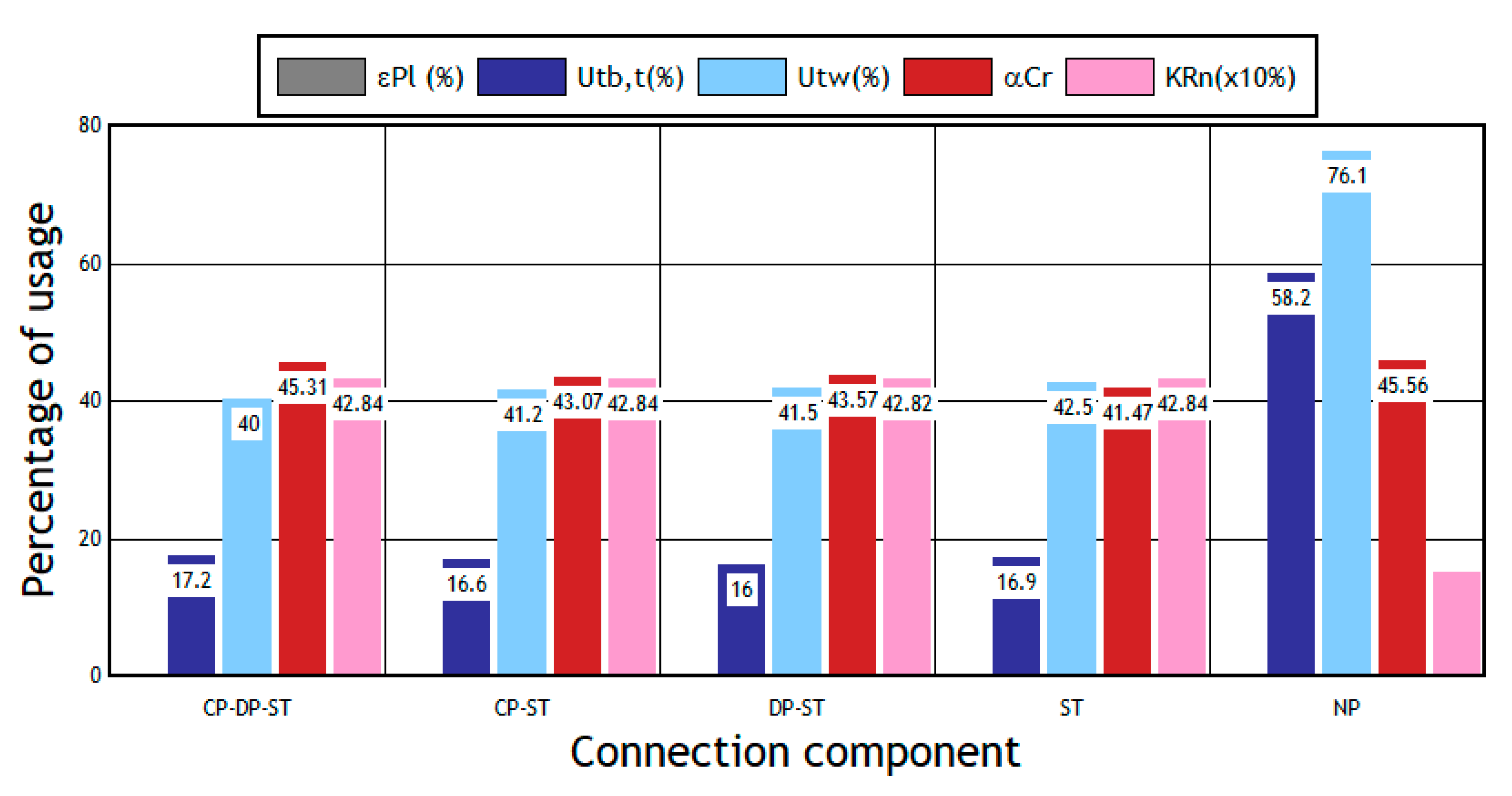
Figure 12, a comparison of maximum and minimum results of the SSA and DR analyses of the 8ES EPC models is schematized through a column chart. Regarding ε P l 
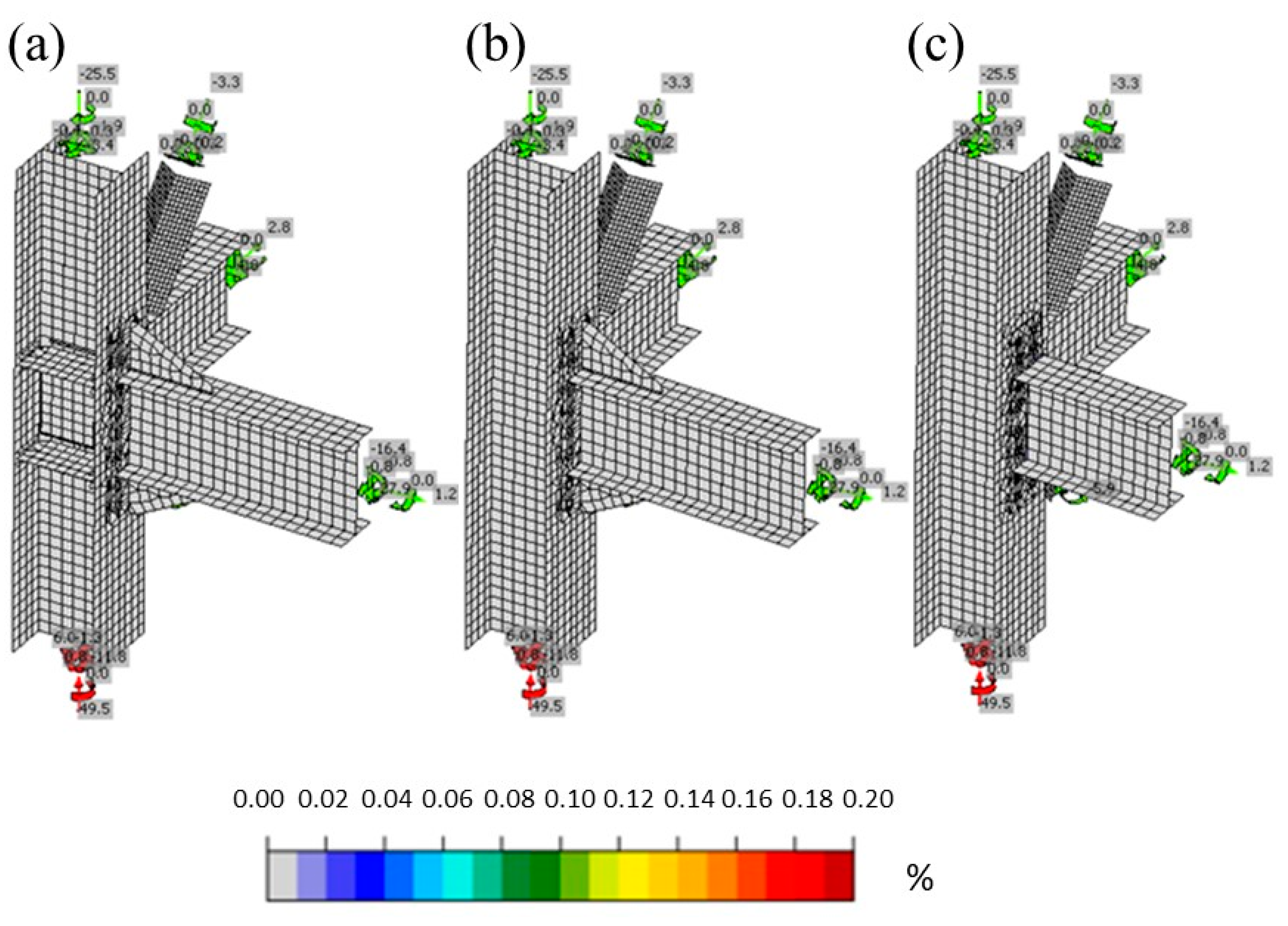
, all the models present a value near 0.00%, which indicates that practically no element or member achieves some degree of yielding, considering a 5.00% deformation as an upper bound value.
For U t b , t , as reinforcing plates in the first three models are deleted, they gradually decrease in value. Such behavior is explained through the elimination of elements with respect to the energy distribution. However, this behavior change in the ST model with a slight rise can be explained based on the decrease in the column stiffness and beam rotation. Regarding the possibility of developing prying loads, their formation is discarded for all the remaining models, even for the NP model, which had the highest U t b , t value of 58.20%, due to the almost zero yielding that happened in all of them. It should be noted that the limit value of the utility is 100%. Therefore, it is estimated that it is still possible to achieve a better degree of optimization for the bolts either by reducing (a) their diameter; (b) the steel grade; or (c) their location on the end plate or (d) by simply changing the type of EPC to one with a smaller number of bolts, according to the load requirements to which this connection is affected.
The values for U t w show a progressive rise in the models studied when the stiffeners are discarded, favoring the energy distribution. When comparing this parameter, the NP model again was the most efficient, with a value of 76.10% (100% is the maximum value). This percentage of utility is much more adequate in terms of efficiency than that of its peer models, exhibiting an absolutely stable level of deformation. The lower quantity of welds used in the NP model should be duly mentioned.
Regarding α C r , even though the buckling value required by code must be greater than 15, ISS developers recommend a value greater than 3 for the connections. Within expectations, the CP-DP-ST model improves the CP-ST, DP-ST, and ST models’ behavior, the latter being the lowest. Additionally, by comparing the values obtained by the CP-ST and DP models, it can be assumed that the doubler plate reinforcement provides a better stiffening effect than the continuity plates in terms of the possibility of local buckling. The unusual behavior is reflected in the result of the NP model, being of greater magnitude, and, consequently, indicating better performance than that of the other models. Since the NP model does not have stiffeners, the end-plate stiffener is the element with the greatest tendency to buckle. Therefore, when discarded, the propensity decreases. On the other hand, as a higher level of deformation in the end plate occurs, as in the welds, it is assumed that energy release occurs mainly through these elements.

5.6. DR Analysis

When contrasting the percentage load vs. deformation, if the first four models show practically identical results, then one of them can represent the performance of any of the other three models. This contrast could be observed in Figure 8 and Figure 9. Then, the first models’ results achieved the same value of 366.70% of the design load as the yield strength. Therefore, it is possible that there is a design load far below the plastic range for the main models studied. Likewise, when focusing on the ultimate capacity, which corresponds to a value of 428.40%, the result indicates that this is 4.28 times greater than the design load. For this reason, it is assumed that these EPC configurations could perfectly withstand higher load demands, still exceeding the linear range, until they reach reasonable ductility values without compromising the safety of the structure.
In the case of the NP model, the design load complies with the yield limit, consistent with the graphic results for this model, achieving a slight yielding in the end plate as in all welds that connect this plate to the beam. As it is affected at the beginning of the yielding of the elements, it is inferred that the connection can go further in its nonlinear behavior since the design capacity is 48.70% greater than the demand. Applying a load up to 1.33 times the actual load is estimated to be entirely safe for the structure.
As a starting point in the structural analysis with MEFBC of a standard EPC configuration, removing the end-plate stiffeners to make the other elements of the connection more participative is the reason for all the results already exposed and stands out as the desired effect. After that, if the results are still remarkably favorable, then the modification of the remaining elements can continue to achieve the most successful optimization for the connection of the structure.

5.7. Complementary Remarks

It is important to emphasize that the normative design of connections is fundamentally dominated by the limits of floor drifts [16], with the stiffness of the connection being an important factor, although not explored in this study. It is worth noting how comprehensive the MEFBCs are and at the same time, delivering such meticulous results. Therefore, these components are reliable, ending a modeling deficit that detracted, in a certain way, from previous studies. Even without implementing the nonlinear geometric analysis, the results achieved were consistent with a large part of those determined in the reference data.
As a future challenge, research should be carried out on the rigidity of the EPC configuration presented in the NP model, which involves FEM analyses to physical tests, if possible. Following the same line, it is also recommended that the connections subject to previous and post verifications of the steel structure should be examined according to the inter-story drifts that govern the current regulations.
The main objective of pre-qualified connections is to obtain a beam-column connection that guarantees adequate behavior of special moment-resisting framed structures versus seismic loads. However, it has been found in this research that pre-qualification requirements are restrictive for small structures, which are commonly used in industrial and mining projects in Chile, leaving an important gap in the design of connections for this type of structures.
In this study, the design of a connection was carried out following the prescriptions of the AISC 358 standard [7], obviating some dimensional requirements that the standard prescribes for the sections of both beams and columns. The resulting connection, designed according to detailed requirements, was subjected to the code’s prescribed loads, including seismic and wind loads for a site with high levels of both hazards. From the nonlinear analysis of the connection, the capacity of the components was obtained, finding an adequate behavior, in which the demand did not exceed the capacity. Additionally, the connection was subjected to a reduction in its components, showing satisfactory results in its overall behavior, which allows obtaining more economical options for this type of connection in small structures subjected to high levels of seismic and wind loads. In this way, this study can contribute to the review of the pre-qualification processes that are currently being carried out [41,42].

6. Conclusions

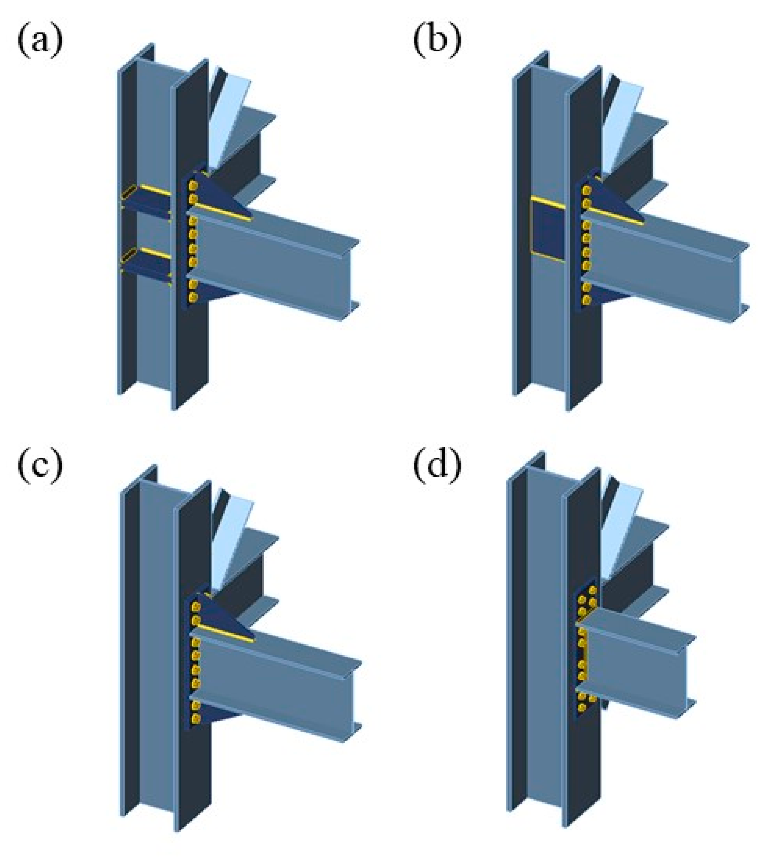
In this research, a model was presented based on the FEMBC for each of the four different configurations of the eight-bolt end-plate connections to analyze their behavior and the component elements when entering the nonlinear range. Such behavior is consistent with the various combinations of monotonic and cyclic loads in the case study. All this work was performed to evaluate the structural redundancy with which the design proposed by AISC 358 is characterized, essentially focusing on its prequalification recommendations and various parameters of the connection behavior. Later, a new configuration optimized for this type of connection was proposed (fifth model), which was also analyzed and compared with the rest of the configurations. From the study, the following can be concluded:
Within the PQLs studied, the beam corresponds to a material savings of 32.34% ± 6.11% for noncompliance; the depth of the beam is the most influential parameter.
In the case of the bolt location parameters, the reduction in the workable gauges directly leads to high material savings.
For the protected area, it is convenient to define a value lower than the proposed PQL, resulting in a lower Mf value.
If the members comply with the design, which determines sections with properties of magnitudes less than the PQL, then it is appropriate to modify the properties of elements before the sections of members, thus preserving the profiles already specified.
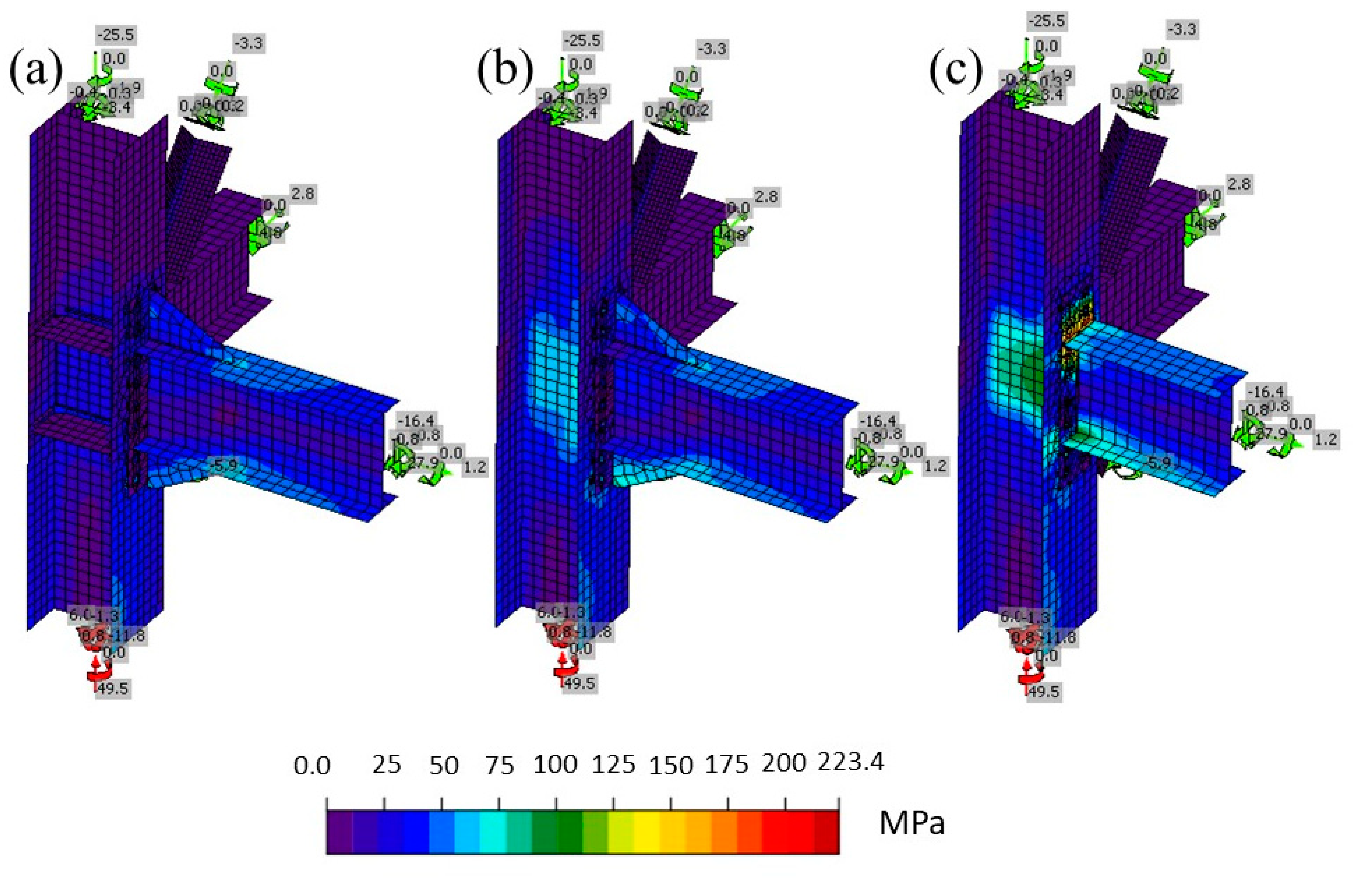
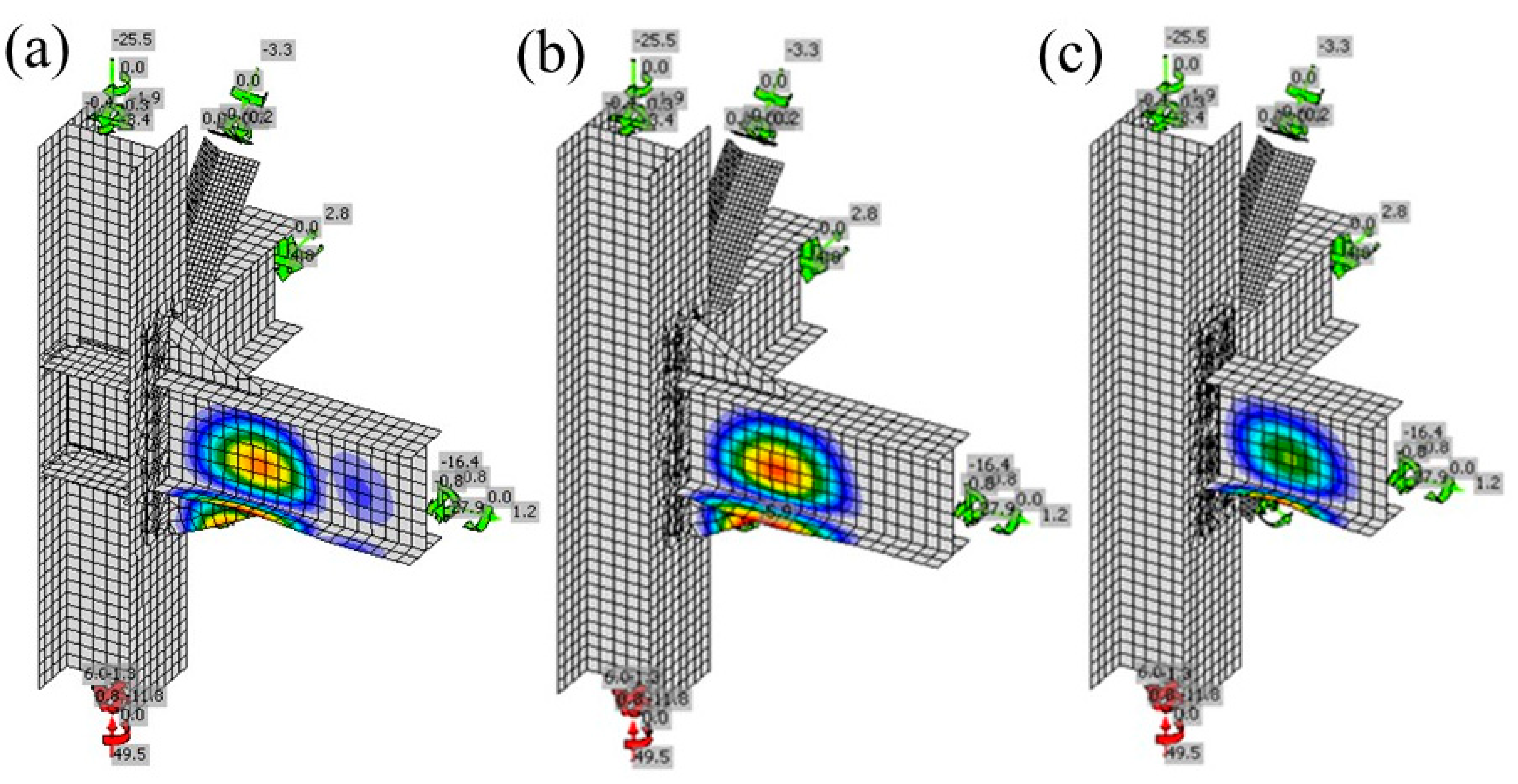
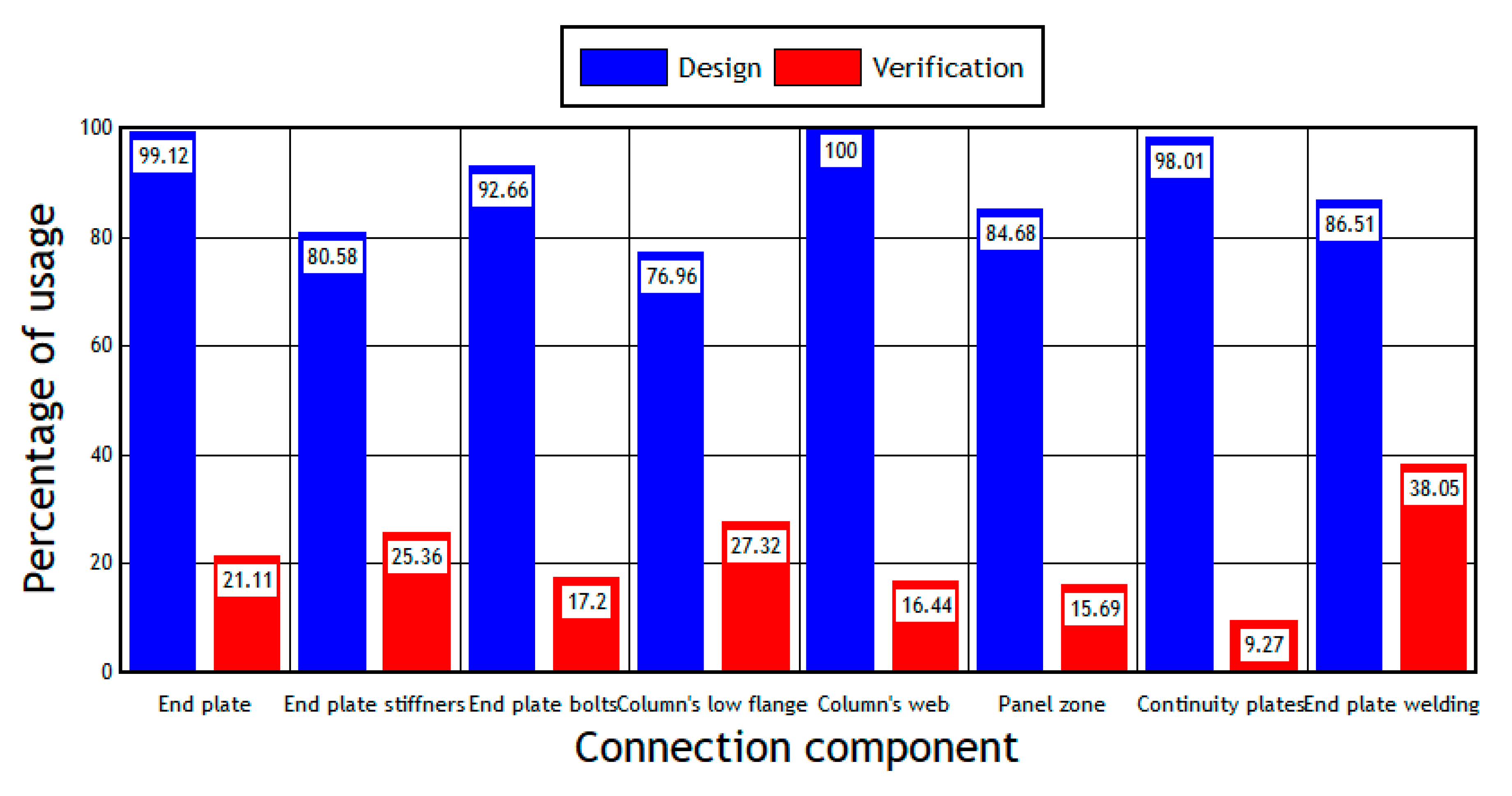
According to the main study models, among the elements examined, those of crucial structural demand are the end plate, the end-plate stiffeners, the column flange attached to the end-plate, and the welds between the beam flanges and the end-plate stiffeners.
The development of lever loads in the bolts of the end plate or the formation of a plastic hinge in the beam is ruled out, which would not lead to the accompanying generation of plastic deformations in the panel area.
Relative to the continuity and double reinforcement plates and their welds, their excessively good performance confirms their unnecessary use.
Regarding end-plate stiffeners, it is estimated that they are the elements with a substantial tendency to buckle and absorb energy; therefore, when removed, the predisposition to buckling decreases, and the energy is better distributed in the other elements. Therefore, it is recommended that when analyzing a standard 8ES EPC configuration for optimization, first, the end-plate stiffeners should be removed. Later, if the products continue to be excessively favorable, then the properties of the remaining elements should be modified.
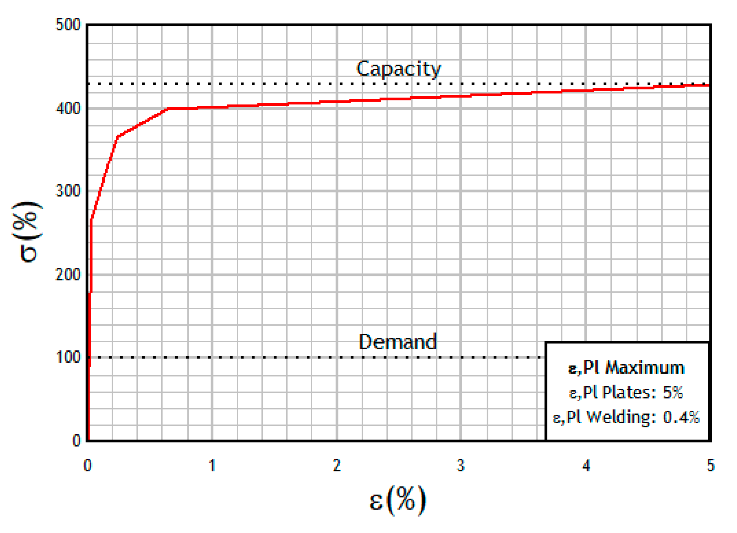
The main study models reveal a yield point that is very far from the design load. Likewise, the design resistance is 4.28 times greater, so it is conjectured that the performance can be increased by approaching either of the two limits, staying in an elastic range or not, by increasing the loads or by decreasing the capacity of the connection.
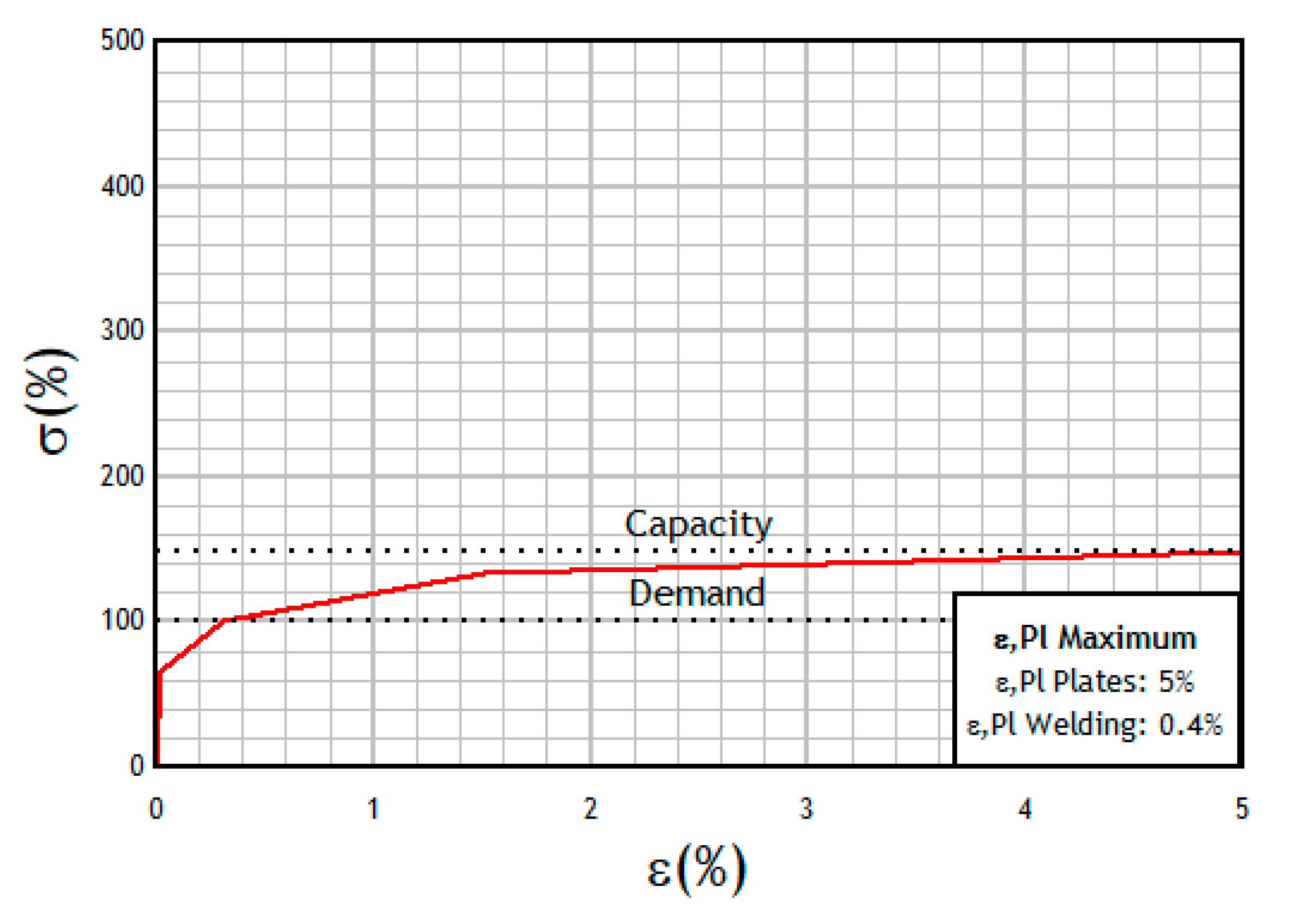
The NP model, for its part, has a yield strength equivalent to the design load; therefore, it is the EPC configuration that obtains the most benefit from its elements. However, for optimization purposes, loads up to 1.33 times greater can be requested in a completely safe way for the structure or, from another angle, by varying the dimensions of the elements, type of steel or the number of bolts if conditions permit.
Based on the previously mentioned conclusions, the design following AISC 358 confirms the restrictive and conservative characteristics for which it is recognized, resulting in an oversized design and prominent structural redundancy. On the other hand, this type of restriction of the pre-qualified connections code results in an important gap in the design of earthquake-resistant connections of small structures, which may well be considered in the future revision of the code.

Author Contributions

Conceptualization, J.C.V.; methodology, J.C.V. and A.L.; software creation, E.A.; software analysis, E.A. and J.C.V.; validation, E.A., J.C.V., and A.L.; results analysis, E.A., A.L., and J.C.V.; results process, E.A.; writing—original draft preparation, E.A.; writing—review and editing, A.L. and J.C.V.; supervision, A.L. and J.C.V. All authors have read and agreed to the published version of the manuscript.

Funding

This research received no external funding.

Data Availability Statement

Acknowledgments

The authors express their gratitude to the PUCV for financing the processing of this article.

Conflicts of Interest

The authors declare no conflict of interest.

References

  1. Zhou, F. Model-Based Simulation of Steel Frames with Endplate Connections. Ph.D. Thesis, University of Cincinnati, Cincinnati, OH, USA, 2005. [Google Scholar]
  2. Ismail, R.E.S.; Fahmy, A.S.; Khalifa, A.M.; Mohamed, Y.M. Numerical study on ultimate behavior of bolted end-plate steel connections. Lat. Am. J. Solids Struct. 2016, 13, 1–22. [Google Scholar] [CrossRef] [Green Version]
  3. Butterworth, J. Finite Element Analysis of Structural Steelwork Beam to Column Bolted Connections; Technical Report (CS 502—Issue 1); Constructional Research Unit, School of Science & Technology, University of Teesside: Middlesbrough, UK, 1999. [Google Scholar]
  4. Mays, T.W. Application of the Finite Element Method to the Seismic Design and Analysis of Large Moment End-Plate Connections. Ph.D. Thesis, Virginia Polytechnic Institute and State University, Blacksburg, VA, USA, 2000. [Google Scholar]
  5. Crisafulli, F.J. Seismic-Resistant Design of Steel Constructions, 5th ed.; Alacero: Buenos Aires, Argentina, 2018. (In Spanish) [Google Scholar]
  6. Murray, T.M.; Sumner, E.A. Design Guide 4: Extended End-Plate Moment Connections: Seismic and Wind Applications, 2nd ed.; American Institute of Steel Construction Inc. (AISC): Chicago, IL, USA, 2003. [Google Scholar]
  7. American Institute of Steel Construction. Prequalified Connections for Special and Intermediate Steel Moment Frames for Seismic Applications; ANSI/AISC 358-16; American Institute of Steel Construction Inc. (AISC, Inc.): Chicago, IL, USA, 2016. [Google Scholar]
  8. Instituto Nacional de Normalización. Construction—Steel Structures—Part 1: Requirements for the Calculation of Steel Structures for Buildings; NCh427/1-2016; Instituto Nacional de Normalización (INN): Santiago de Chile, Chile, 2016. (In Spanish) [Google Scholar]
  9. Instituto Nacional De Normalización. NCh2369 of 2003—Seismic Design of Structures and Industrial Facilities; Instituto Nacional De Normalización (INN): Santiago de Chile, Chile, 2003. (In Spanish) [Google Scholar]
  10. Maggi, Y.I.; Goncalves, R.M.; Leon, R.T.; Ribeiro, L.F.L. Parametric analysis of steel bolted end plate connections using finite element modeling. J. Constr. Steel Res. 2005, 61, 689–708. [Google Scholar] [CrossRef]
  11. Sherbourne, A.N.; Bahaari, M.R. 3D simulation of end-plate bolted connections. J. Struct. Eng. 1994, 120, 3122–3136. [Google Scholar] [CrossRef]
  12. Ghassemieh, M.; Jalalpour, M.; Gholampour, A.A. Numerical evaluation of the extended endplate moment connection subjected to cyclic loading. Curr. Adv. Civ. Eng 2014, 2, 35–43. [Google Scholar]
  13. Díaz, C.; Victoria, M.; Martí, P.; Querin, O.M. FE model of beam-to-column extended endplate joints. J. Constr. Steel Res. 2011, 67, 1578–1590. [Google Scholar] [CrossRef]
  14. Shi, G.; Shi, Y.; Wang, Y.; Bradford, M.A. Numerical simulation of steel pretensioned bolted end-plate connections of different types and details. Eng. Struct. 2008, 30, 2677–2686. [Google Scholar] [CrossRef]
  15. Tahir, M.; Juki, I.; Yong, L.H.; Mohammad, S.; Ngian, S.P. Finite element analysis of flush end-plate connections connected to column web. Int. J. Steel Struct. 2011, 11, 247–258. [Google Scholar] [CrossRef]
  16. Gallegos, M.; Nuñez, E.; Herrera, R. Numerical study on cyclic response of end-plate biaxial moment connection in box columns. Metals 2020, 10, 523. [Google Scholar] [CrossRef]
  17. Morrison, M.; Quayyum, S.; Hassan, T. Performance enhancement of eight bolt extended end-plate moment connections under simulated seismic loading. Eng. Struct. 2017, 151, 444–458. [Google Scholar] [CrossRef]
  18. Moura, P.; Carvalho, H.; Figueiredo, L.; Aires, P.; Bártolo, R. Unitary model for the analysis of bolted connections using the finite element method. Eng. Fail. Anal. 2019, 104, 308–320. [Google Scholar]
  19. Hong, J.K.; Park, Y.C.; Sim, H.B. Cyclic Perofrmance of Easy Quality (EQ) Moment Connections as an Intermediate Steel Moment Frame. Int. J. Steel Struct. 2019, 19, 1272–1282. [Google Scholar] [CrossRef]
  20. Mahjoob, S.; Erfani, S. Parametric study of Stub-Beam Bolted Extended End-Plate connection to box-columns. J. Constr. Steel Res. 2020, 171, 106155. [Google Scholar] [CrossRef]
  21. Hoseinzadeh, M.; Jahanian, M. Behaviour of Steel Deep Beams in Moment Frames with Web Opening Subjected to Lateral Loading. Int. J. Steel Struct. 2020, 20, 1482–1497. [Google Scholar] [CrossRef]
  22. Hajjar, J.F.; Dexter, R.J.; Ojard, S.D.; Ye, Y.; Cotton, S.C. Continuity plate detailing for steel moment-resisting connections. Eng. J. 2003, 40, 189–211. [Google Scholar]
  23. Mashaly, E.; El-Heweity, M.; Abou-Elfath, H.; Osman, M. Behavior of four-bolt extended end-plate connection subjected to lateral loading. Alex. Eng. J. 2011, 50, 79–90. [Google Scholar] [CrossRef] [Green Version]
  24. Chasten, C.P.; Lu, L.W.; Driscoll, G.C. Prying and shear in end-plate connection design. J. Struct. Eng. 1992, 118, 1295–1311. [Google Scholar] [CrossRef]
  25. Tartaglia, R.; D’Aniello, M.; Rassati, G.A.; Swanson, J.A.; Landolfo, R. Full strength extended stiffened end-plate joints: AISC vs recent European design criteria. Eng. Struct. 2018, 159, 155–171. [Google Scholar] [CrossRef]
  26. Francavilla, A.B.; Latour, M.; Piluso, V.; Rizzano, G. Design of full-strength full-ductility extended end-plate beam-to-column joints. J. Constr. Steel Res. 2018, 148, 77–96. [Google Scholar] [CrossRef]
  27. Lim, C.; Choi, W.; Sumner, E.A. Low cycle fatigue life prediction using a four-bolt extended unstiffened end plate moment connection. Eng. Struct. 2012, 41, 373–384. [Google Scholar] [CrossRef]
  28. Bahaari, M.R.; Sherbourne, A.N. Structural behaviour of End-Plate Bolted connections to Stiffened Columns. J. Struct. Eng. 1996, 122, 926–935. [Google Scholar] [CrossRef]
  29. Abdalla, K.M.; Abu-Farsakh, G.A.R.; Barakat, S.A. Experimental investigation of force-distribution in high-strength bolts in extended end-plate connections. Steel Compos. Struct. 2007, 7, 87–103. [Google Scholar] [CrossRef]
  30. Tahir, M.M.; Sulaiman, A. Experimental tests on extended end-plate connection with variable parameters. Int. J. Steel Struct. 2008, 8, 369–381. [Google Scholar]
  31. Tartaglia, R.; D’Aniello, M.; Landolfo, R. The influence of rib stiffeners on the response of extended end-plate joints. J. Constr. Steel Res. 2018, 148, 669–690. [Google Scholar] [CrossRef]
  32. Rizzo, F.; Di Lorenzo, G.; Formisano, A.; Landolfo, R. Time-dependent corrosion wastage model for wrought iron structures. J. Mater. Civ. Eng. 2019, 31, 04019165. [Google Scholar] [CrossRef]
  33. Di Lorenzo, G.; Rizzo, F.; Formisano, A.; Landolfo, R.; Guastaferro, A. Corrosion wastage models for steel structures: Literature review and a new interpretative formulation. Key Eng. Mater. 2019, 813, 209–2014. [Google Scholar] [CrossRef]
  34. Di Benedetto, S.; Francavilla, A.B.; Latour, M.; Cavallaro, G.F.; Piluso, V.; Rizzano, G. Seismic behavior of moment-resisting frames with conventional and innovative connections. Symmetry 2020, 12, 2091. [Google Scholar] [CrossRef]
  35. Autodesk, Inc. Autodesk Robot. Structural Analysis Professional 2019; Windows x64; Autodesk, Inc.: San Rafael, CA, USA, 2018. [Google Scholar]
  36. American Institute of Steel Construction. ANSI/AISC 341-16, Seismic Provisions for Structural Steel Buildings; American Institute of Steel Construction Inc. (AISC, Inc.): Chicago, IL, USA, 2016. [Google Scholar]
  37. American Institute of Steel Construction. ANSI/AISC 360-16, Specification for Structural Steel Buildings; American Institute of Steel Construction Inc. (AISC, Inc.): Chicago, IL, USA, 2016. [Google Scholar]
  38. IDEA StatiCa s.r.o. IDEA StatiCa; Windows x64; IDEA StatiCa s.r.o.: Brno, Czec Republic, 2019. [Google Scholar]
  39. IDEA StatiCa UK. Unbalanced Forces. Available online: https://techscience.freshdesk.com/support/solutions/articles/19000031167-unbalanced-forces (accessed on 2 January 2019).
  40. Tremblay, R.; Filiatrault, A.; Timler, P.; Bruneau, M. Performance of steel structures during the 1994 Northridge earthquake. Can. J. Civ. Eng. 1995, 22, 338–360. [Google Scholar] [CrossRef]
  41. Tartaglia, R.; D’Aniello, M.; Landolfo, R. Numerical simulations to predict the seismic performance of a 2-story steel moment-resisting frame. Materials 2020, 13, 4831. [Google Scholar] [CrossRef]
  42. Campiche, A.; Costanzo, R. Evolution of ec8 seismic design rules for x concentric bracings. Symmetry 2020, 12, 1807. [Google Scholar] [CrossRef]
Figure 1. Isometric view of the structural model.
Metals 11 00243 g001
Figure 2. (a) Plan and (b) elevation view of the case study. Dimension are in meters.
Metals 11 00243 g002
Figure 3. Isometric view of the eight-bolt extended stiffened (8ES) end-plate connection (EPC) fully reinforced (continuity plate-doubler plate-stiffener plate (CP-DP-ST)) connection.
Metals 11 00243 g003
Figure 4. Lateral and front view of the pre-qualified connection designed. Dimensions in millimeters.
Metals 11 00243 g004
Figure 5. Isometric view of the 8ES EPC (a) only with continuity and stiffener plates (CP-ST), (b) only with double reinforcement and stiffener plates (DP-ST), (c) only with stiffener plates (ST) and (d) without reinforcement plate (NP) connections.
Metals 11 00243 g005
Figure 6. Equivalent stresses computed on the connection for the three 8ES EPC models: (a) CP-DP-ST, (b) ST, and (c) NP.
Metals 11 00243 g006
Figure 7. Strains computed on the connection for the three 8ES EPC models: (a) CP-DP-ST, (b) ST, and (c) NP.
Metals 11 00243 g007
Figure 8. Local bucking modes computed on the connection for the three 8ES EPC models: (a) CP-DP-ST, (b) ST, and (c) NP.
Metals 11 00243 g008
Figure 9. Percentage of strength vs. percentage of strain 8ES EPC NP CP-DP-ST.
Metals 11 00243 g009
Figure 10. Percentage of strength vs. percentage of strain 8ES EPC NP.
Metals 11 00243 g010
Figure 11. Comparison of the utility percentages of elements designed vs. nonlinear assessment.
Metals 11 00243 g011
Figure 12. Computed demands (in %) for different components of the studied connections.
Metals 11 00243 g012
Table 1. Beam’s characteristics vs. prequalification limits.
ParameterPrequalification Lower BoundaryParameter’s ValuePrequalification Upper BoundaryVerification
d b (mm)457.00270.00914.00No
b b f (mm)190.00135.00311.00No
t b f (mm)14.0010.2025.00No
b / t -6.628.42Yes
L b / d b 7.0022.22-Yes
d b = depth of the beam. b b f = flange width of the beam. t b f = flange thickness of the beam. b / t = ( b b f / 2 ) / t b f = beam compactness ratio. L b / d b = beam’s span length/depth of the beam ratio.
Table 2. Column characteristics vs. prequalification limits.
ParameterPrequalification Lower BoundaryParameter’s ValuePrequalification Upper BoundaryVerification
d c (mm)-240.00914.40Yes
b / t -7.068.42Yes
h c / t c w -16.4066.38Yes
d c = depth of the column. b / t = ( b c f / 2 ) / t c f = column flange compactness ratio. h c / t c w = column web compactness ratio. h c = column height.
Table 3. Bolt location characteristics vs. prequalification limits.
ParameterPrequalification Lower BoundaryParameter’s ValuePrequalification Upper BoundaryVerification
g   (mm)127.0075.00152.00No
p f i (mm)41.0040.0051.00No
p f o (mm)41.0040.0051.00No
p b (mm)89.0055.0095.00No
g = horizontal distance between bolts. p f i = vertical distance from the inside of a beam tension flange to the nearest inside bolt row. p f o = vertical distance from the outside of a beam tension flange to the nearest outside bolt row. p b = vertical distance between the inner and outer row of bolts in eight-bolt stiffened extended end-plate moment connection.
Table 4. Protected zone characteristics vs. prequalification limits.
ParameterParameter’s ValuePrequalification Upper BoundaryVerification
L s t   +   t p (mm)244405No
L s t   +   t p = protected zone length. L s t = length of the end-plate stiffener. t p = thickness of the end plate.
Table 5. Essential results of the 8ES EPC CP-DP-ST model.
ParameterPrequalification Lower BoundaryParameter’s ValuePrequalification Upper BoundaryVerification
ε P l (%)-0.005.00Yes
U t b , t (%)-17.20100.00Yes
U t w (%)-40.00100.00Yes
α C r 15.00 (3.00)45.31-Yes
K R n   ( % ) 100.00428.40-Yes
ε P l = main membrane deformation for zones not susceptible to buckling. U t b , t = F t b / φ R n b , t . tensile bolts utilization ratio. F t b = tensile force on the bolt. φ R n b , t = bolt tensile strength. U t w = F n w / φ R n w = weld utilization ratio. F n w = force on critical weld element. φ R n w = weld strength. α C r = critical buckling factor. K R n = maximum load to design load ratio.
Table 6. Essential results of the 8ES EPC ST model.
ParameterPrequalification Lower BoundaryParameter’s ValuePrequalification Upper BoundaryVerification
ε P l (%)-0.005.00Yes
U t b , t (%)-16.90100.00Yes
U t w (%)-42.50100.00Yes
α C r 15.00 (3.00)41.47-Yes
K R n   (%)100.00428.40-Yes
Table 7. Essential results of the EPC 8E NP model.
ParameterPrequalification Lower BoundaryParameter’s ValuePrequalification Upper BoundaryVerification
ε P l (%)-0.035.00Yes
U t b , t (%)-58.20100.00Yes
U t w (%)-76.10100.00Yes
α C r 15.00 (3.00)45.56-Yes
K R n   (%)100.00148.70-Yes
Table 8. Beam parameter dimensional savings percentages.
ParameterPercentage under the Prequalification Lower Boundary (%)Parameter’s Value (mm)Percentage under the Prequalification Upper Boundary Bound (%)
d b 40.92270.0070.46
b b f 28.95135.0056.59
t b f 27.1410.2059.20
d b = depth of the beam. b b f = flange width of the beam. t b f = flange thickness of the beam.
Table 9. Percentages of the dimensional noncompliance of the bolt location parameters.
ParameterPercentage under the Prequalification Lower Boundary (%)Parameter’s Value (mm)Percentage under the Prequalification Upper Boundary Bound (%)
g 40.9475.0050.66
p f i 2.4440.0021.57
p f o 2.4440.0021.57
p b 38.2055.0042.11
g = horizontal distance between bolts. p f i = vertical distance from the inside of a beam tension flange to the nearest inside bolt row. p f o = vertical distance from the outside of a beam tension flange to the nearest outside bolt row. p b = vertical distance between the inner and outer row of bolts in eight-bolt stiffened extended end-plate moment connection.
Table 10. Percentage of the dimensional noncompliance of the protected zone parameters.
ParameterParameter’s Value (mm)Percentage under the Prequalification Upper Boundary Bound (%)
L s t + t p 24439.75
L s t + t p = protected zone length. L s t = length of the end-plate stiffener. t p = thickness of the end plate.
Publisher’s Note: MDPI stays neutral with regard to jurisdictional claims in published maps and institutional affiliations.

