Article

Enhancement of Uniform Elongation by Temperature Change during Tensile Deformation in a 0.2C TRIP Steel

by
Noriyuki Tsuchida
1,* and
Stefanus Harjo
2
1
Graduate School of Engineering, University of Hyogo, 2167 Shosha, Himeji 671-2280, Japan
2
J-PARC Center, Japan Atomic Energy Agency, 2-4 Shirane Shirakata, Tokai-mura, Ibaraki 319-1195, Japan
*
Author to whom correspondence should be addressed.
Metals 2021, 11(12), 2053; https://doi.org/10.3390/met11122053
Submission received: 18 November 2021 / Revised: 6 December 2021 / Accepted: 15 December 2021 / Published: 18 December 2021
(This article belongs to the Special Issue Advances in High-Strength Low-Alloy Steels)

Abstract

:
It is important to control the deformation-induced martensitic transformation (DIMT) up to the latter part of the deformation to improve the uniform elongation (U.El) through the TRIP effect. In the present study, tensile tests with decreasing deformation temperatures were conducted to achieve continuous DIMT up to the latter part of the deformation. As a result, the U.El was improved by approximately 1.5 times compared with that in the tensile test conducted at 296 K. The enhancement of the U.El in the temperature change test was discussed with the use of neutron diffraction experiments. In the continuous DIMT behavior, a maximum transformation rate of about 0.4 was obtained at a true strain (ε) of 0.2, which was larger than that in the tensile test at 296 K. The tensile deformation behavior of ferrite (α), austenite (γ), and deformation-induced martensite (α′) phases were investigated from the viewpoint of the fraction weighted phase stress. The tensile test with a decreasing deformation temperature caused the increase of the fraction weighted phase stress of α and that of α′, which was affected by the DIMT behavior, resulting in the increase in the work hardening, and also controlled the ductility of α and α′, resulting in the enhancement of the U.El. Especially, the α phase contributed to maintaining high strength instead of α′ at a larger ε. Therefore, not only the DIMT behavior but also the deformation behavior of γ, α, and α′ are important in order to improve U.El due to the TRIP effect.

1. Introduction

The transformation-induced plasticity (TRIP) effect is a strengthening mechanism of metals that makes efficient use of the deformation-induced martensitic transformation (DIMT) of the retained austenite (γR) and is expected to improve the ductility or elongation [1,2,3,4,5,6]. Because the TRIP effect also has been utilized in advanced high-strength steels, there is great interest in understanding how the DIMT controls and the constituent phases interact to obtain superior mechanical properties [2,4,7]. In various studies on the TRIP effect, the DIMT behavior of γR is key information for discussing the enhancement of the uniform elongation (U.El) through the TRIP effect [4,5,6,7,8,9,10,11,12]. Blondé et al. investigated the mechanical stability of γR using high-energy X-ray diffraction during tensile tests at various deformation temperatures [3]. They made clear that the mechanical stability of γR was influenced by a complex interplay among the carbon concentration in γR, the grain orientation, the load partitioning and the deformation temperature. Based on previous studies, it is desirable that γR is stable in the early stage of deformation and that the DIMT is temporarily induced up to the latter part of the tensile deformation in order to obtain a better TRIP effect [8,13,14,15]. On the other hand, in cases where the improved U.El was obtained in various TRIP steels, all of the γR was not necessarily transformed into deformation-induced martensite (α′) at the maximum load point [7,9,16]. This means that the DIMT can be effectively used to improve the U.El through the TRIP effect. If such DIMT behavior can be achieved, it is obvious that the U.El can be improved. However, such DIMT behavior is generally very difficult to obtain in tensile tests conducted at a constant temperature or strain rate [4,7,14,16]. The DIMT behavior depends on the temperature and the volume fraction of α′ at a given true strain (ε) generally increases with a decrease in the deformation temperature [3,4,7,14,15]. It is expected that the DIMT can be temporarily induced up to the latter part of deformation by decreasing the temperature during the tensile deformation. We believed that this type of test would help to clarify the conditions required for the DIMT to improve the U.El through the TRIP effect. Therefore, we attempted to control the DIMT behavior by changing the temperature during the tensile deformation. In the present study, we conducted tensile tests during which the deformation temperature was decreased in order to control the DIMT behavior, and we investigated the improvement of the U.El. The DIMT behaviors were investigated by X-ray and neutron diffraction experiments [4,17,18,19]. The tensile deformation behaviors of the austenite (γ), ferrite (α), and α′ phases of a TRIP steel were also studied through neutron diffraction experiments [4,7,17]. Harjo et al. analyzed the phase stress of α′ with in situ neutron diffraction experiments and discussed the stress contribution from α′ to the flow stress of a TRIP steel [7]. The quantitative estimation of α′ based on this procedure must play an important role in the discussions for the role of α′ on the tensile deformation behavior of TRIP steels. From the obtained results, the relationships among the U.El, the DIMT behavior, and the deformation behavior of each phase were summarized and the DIMT conditions for an efficient TRIP effect were discussed.

2. Experimental Procedures

This study used a TRIP-aided multi-microstructure steel obtained from a 0.2C steel (0.2C, 1.51Si, 1.22Mn, 0.022P, 0.0025S, 0.039Al by mass%) [7,12,18]. The ingots were vacuum melted, hot rolled to a thickness of 8 mm by finishing at 1123 K, and then cold rolled to a thickness of 2.2 mm. To obtain the TRIP steel, the cold-rolled steel sheets were annealed at 1073 K for 1.8 ks using a fluid bath under a N2 atmosphere, followed by air cooling to 998 K. The sheets were then isothermally held at 673 K for 180 s followed by air cooling. Surface grinding was conducted to obtain a final thickness of 1.8 mm. Microstructure observation was performed by using a scanning electron microscope JEOL-7001F (SEM, JEOL, Tokyo, Japan) equipped with a measurement system of electron back scattering diffraction (EBSD) (TSL Solutions, Sagamihara, Japan). The EBSD pattern was analyzed while the possible phases were set as body-centered cubic (bcc) and face-centered cubic, and the scanning pitch was 0.2 μm.
Static tensile tests were conducted at a strain rate of 3.3 × 10⁻⁴ s−1 at various deformation temperatures between 77 and 573 K by using a gear-driven type tensile test machine Instron 5082 (Instron, Kawasaki, Japan) equipped with a 100 kN load cell. Here, tensile test specimens with a gage width of 5 mm, a gage length of 25 mm, and a thickness of 1.8 mm were prepared. The deformation temperatures were controlled by using liquid nitrogen (77 K), an environmental chamber (123–373 K), and a heating furnace (373–573 K) [14,15,20]. Tensile test specimens that were interrupted at various ε during tensile deformation at various temperatures were also prepared for calculating the volume fractions of γR (Vγ) and α′ (Vα′). Vγ, Vα′, and the carbon content of γR in the 0.2C TRIP steel were estimated by X-ray diffraction experiments using Cu-Kα radiation (Rigaku, Tokyo, Japan) [7,14,15,18]. The quantitative estimations of Vγ and Vα′ by X-ray diffraction were based on the principle that the total integrated intensity of all diffraction peaks for each phase in a mixture was proportional to the phase volume fraction [14,15,20].
We also conducted tensile tests during which the deformation temperature was changed during the tensile deformation to control the DIMT behavior. In this study, two types of tests were performed, as shown in Figure 1. The deformation temperature range was between 123 and 373 K, using the environmental chamber. Tensile test A, as seen in Figure 1a, was conducted up to ε of about 0.15 at 373 K and was unloaded. Then, the test specimens were cooled to various deformation temperatures below 296 K, and resumed tensile deformations. The strain rate of test A was 3.3 × 10⁻⁴ s−1. Test B, as shown in Figure 1b, was conducted up to ε of about 0.2 at 373 K with a strain rate of 3.3 × 10⁻⁴ s−1 and was unloaded. The tensile test was then resumed with a strain rate of 1.0 × 10⁵ s1 at 323 K up to ε of about 0.3, and subsequently continued at the same strain rate with a gradual decrease in the deformation temperature. Test B was stopped when the maximum load point was reached at 123 K.
In test B, tensile test specimens that were interrupted at various ε during the test were prepared to evaluate the evolutions of Vα′, the residual phase strain ( ε p h a s e r ), and the residual lattice strain ( ε h k l r ) using neutron diffraction. The neutron diffraction experiments were conducted at TAKUMI [4,7,17], the high-resolution and high-intensity time-of-flight (TOF) neutron diffractometer for engineering sciences at MLF of J-PARC. Diffraction patterns in the loading and transverse (normal to the loading direction) directions were measured simultaneously by using two 90° scattering detector banks. The neutron diffraction patterns for both the loading and transverse directions were collected at detector areas integrated at ±15° horizontally and ±15° vertically. The diffraction patterns were measured for 600 s. ε h k l r and volume fraction of α (Vα), Vγ, and Vα′ were calculated from the collected diffraction patterns. ε h k l r was calculated by using the following equation, which is based on peak analyses [4,7,17]:
ε h k l r = d h k l d h k l 0 d h k l 0
where dhkl is the lattice spacing after the tensile deformation and d h k l 0 is the lattice spacing before the deformation. d h k l 0 of γ and α were obtained from peak analyses before deformation, but α′ did not exist before deformation in this case [4,7]. The peak analyses of α′ were performed based on previous studies by Harjo et al. [7]. Data analyses of α′ were conducted by a multi-peak fitting method consisting of α and α′. In the present analyses, α′ was considered to be bcc, but with a higher carbon content than bcc. This was because the reliability of separating the a and c axes is low due to the small volume fraction of α′ and because the carbon content dependence of α′ on the c/a ratio is not clear. In this study, d h k l 0 of α′ was estimated from the calculated lattice constant of α′ as follows [21,22]:
a α = ρ γ 2 ρ α 3 a γ
where aα′, aγ, ρα′, and ργ are lattice constants and the atomic densities of α′ and γ [20,21]. aα′ before the deformation (aα′,0) of the present TRIP steel was described by aγ before deformation (aγ,0) [7]:
aα’,0 = 0.8037 aγ,0
d h k l 0 for α′ was calculated from aα′,0 estimated by Equation (3) and was used for estimating ε h k l r of α′ using Equation (1) [4,7]. In the present study, the data from the neutron diffraction patterns in the loading direction were mainly analyzed because the peaks between α and α′ in the patterns of the transverse direction were difficult to separate due to the proximity of the peaks caused by the Poisson effect [4,7]. ε p h a s e r was estimated as the averaged value of ε h k l r for each phase ((111), (200), (311) for γ and (110), (200), (211) for α and α′ phases, respectively) [4,7]. Vα, Vγ, and Vα′ were calculated from the integrated intensities obtained by neutron diffraction experiments [4,7]. In terms of the change in Vα′, which is associated with the DIMT behavior, the analyses of the α′ peaks were evaluated as having a lower reliability because those peaks were low and broadened. Therefore, the increase in Vα′ was considered to be the decrease in Vγ [4].
In situ neutron diffraction measurements during tensile test were also carried out at constant deformation temperatures, 296 K, 245 K, 188 K, and 128 K, to investigate the effect of deformation temperature on phase strain in the TRIP steel. The deformation temperatures were controlled by a liquid nitrogen cooling system equipment [17,23]. The temperature was monitored using a thermocouple attached on the specimen at the grip parts. Macroscopic strains were measured by a strain gage. The size of incident beam slit was 5 mm × 5 mm, and a pair of radial collimators viewing 5 mm width was adopted. The tensile test was conducted by a step-increasing load control with 300 s holding time in the elastic region and with the initial strain rate of 2 × 10⁵ s1 in the plastic region. The data for the plastic region was then sliced per 300 s or 600 s and the measurements were performed up to the tensile strength (TS). Lattice strains and phase strains for the in situ neutron diffraction experiments are calculated based on the same concept such as Equation (1) [4,7,15,16].

3. Results and Discussion

3.1. Effect of Temperature on Tensile Properties in a 0.2C TRIP Steel

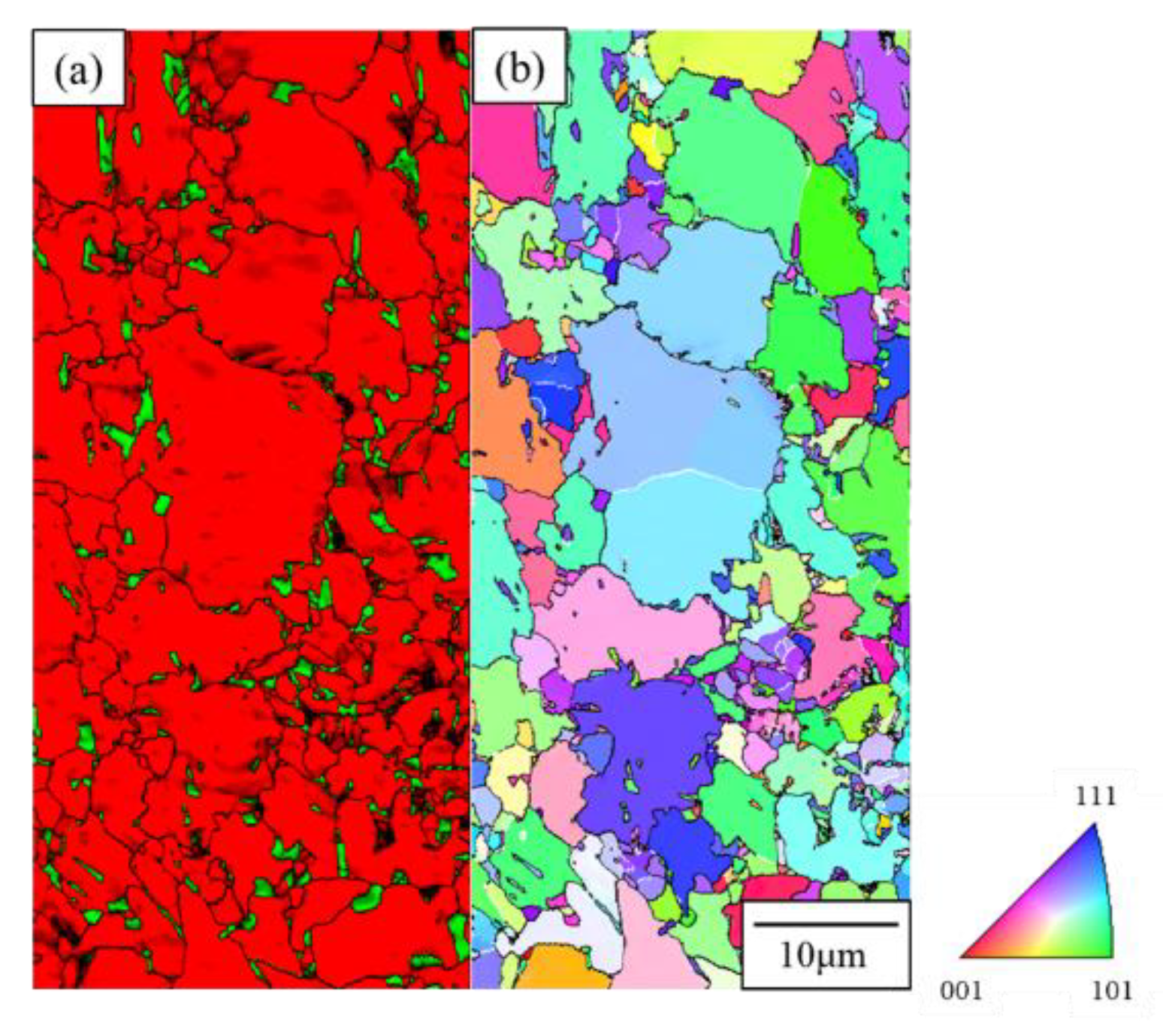
Figure 2 shows the SEM-EBSD phase map (a) and inverse pole figure map (b). In the phase map, red and green indicate α and γ, respectively. Note that ferrite and bainite were treated as one α phase here. γR was dispersed almost uniformly at the α grain boundaries. We also observed the microstructure using an optical microscope in previous studies [18]. In the optical micrograph, γR was also dispersed in bainite, and the average size of γR was approximately 1 μm. The volume fractions of ferrite, bainite, and γR were 67.6, 21.8, and 10.6%, respectively, and the carbon content of γR was 1.28 mass% [7,12].
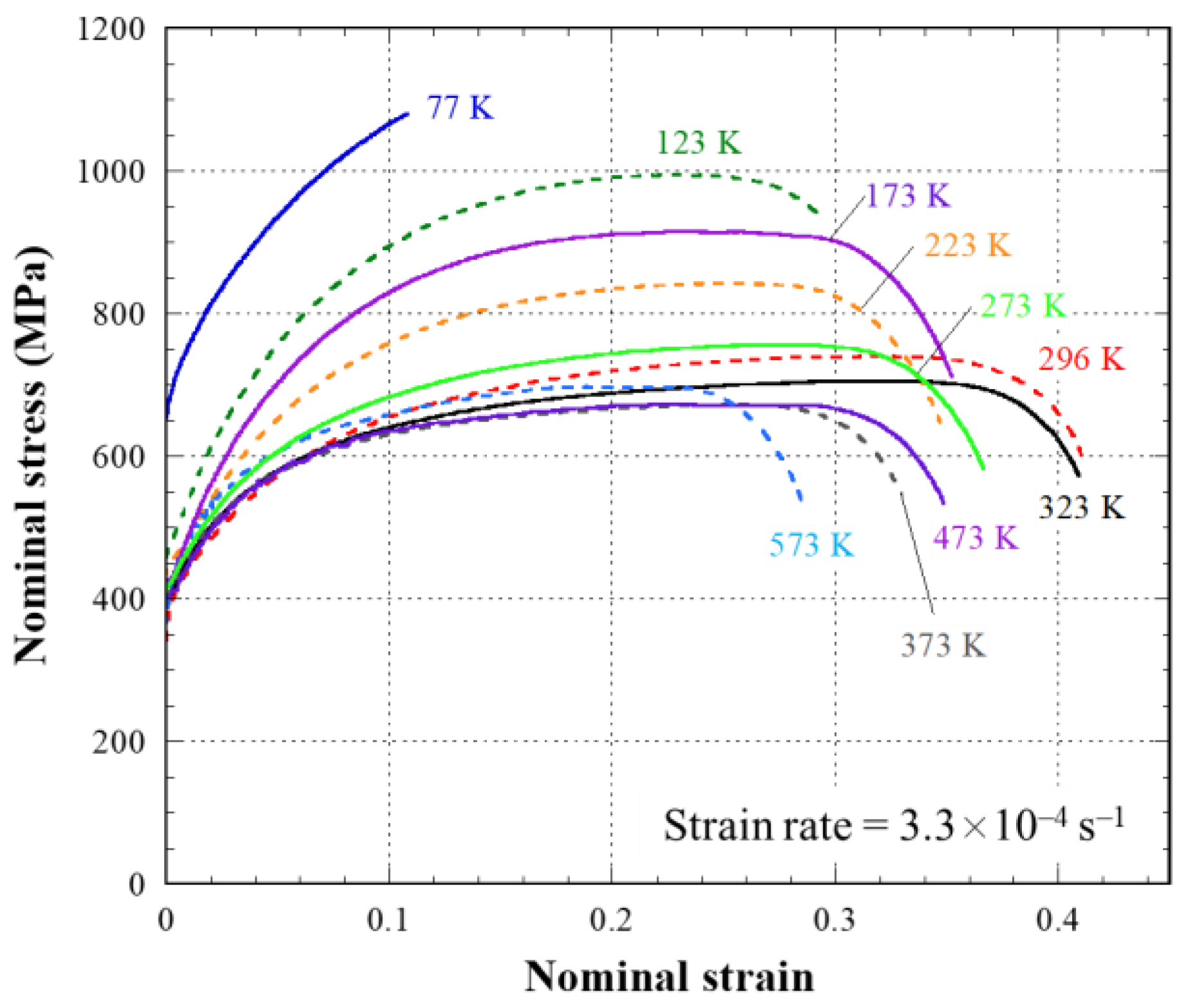
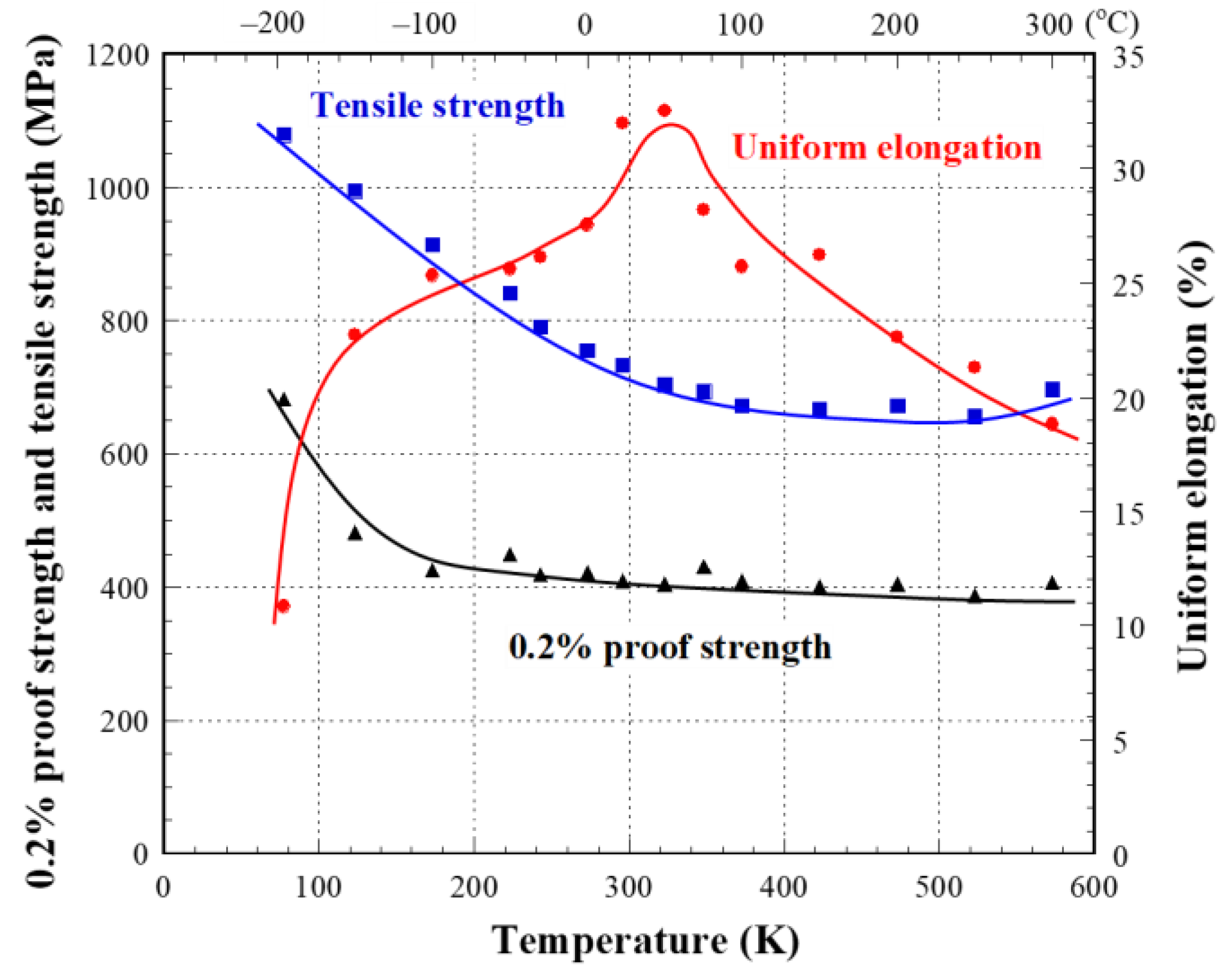
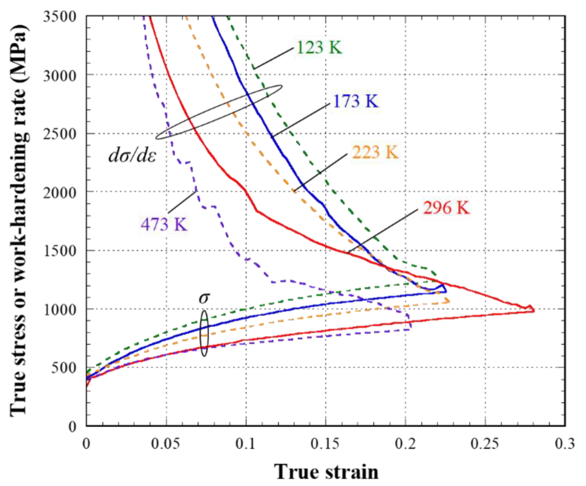
Figure 3 shows the nominal stress (s)–nominal strain (e) curves of the 0.2C TRIP steel at various temperatures between 77 and 573 K. s increased with the decrease in temperature and failed in a brittle manner at 77 K. U.El and total elongation indicated better values at 296 and 323 K. Almost the same s–e curves and mechanical properties were exhibited at 373 and 473 K. U.El and total elongation decreased with the increase in deformation temperature, but TS increased slightly when the temperature increased from 473 to 573 K. This seems to be associated with the deformation-induced bainitic transformation of γR [5,20]. Figure 4 shows the 0.2% proof strength (0.2% PS), TS, and U.El as functions of the deformation temperature. The 0.2% PS and TS increased with the decrease in temperature. The 0.2% PS decreased slightly near 223 K and increased again below 173 K. The γR seems to be transformed to α′ before yielding near 223 K. Thus, the temperature of 223 K is close to the Msσ point of the present TRIP steel [14,20,24,25]. U.El showed a maximum value at 296 and 323 K. Figure 5 shows the true stress (σ) and work-hardening rate (/) as a function of ε at various temperatures. / at a given ε increased with the decrease in temperature. As shown in Figure 4 that ε at the plastic instability, i.e., U.El, was the largest at 296 K, the / at ε > 0.2 at 296 K was also larger than those at temperatures < 296 K. This is associated with the change in Vα′ due to the DIMT during tensile deformation [1,5].

3.2. Mechanical Properties Obtained from Test A

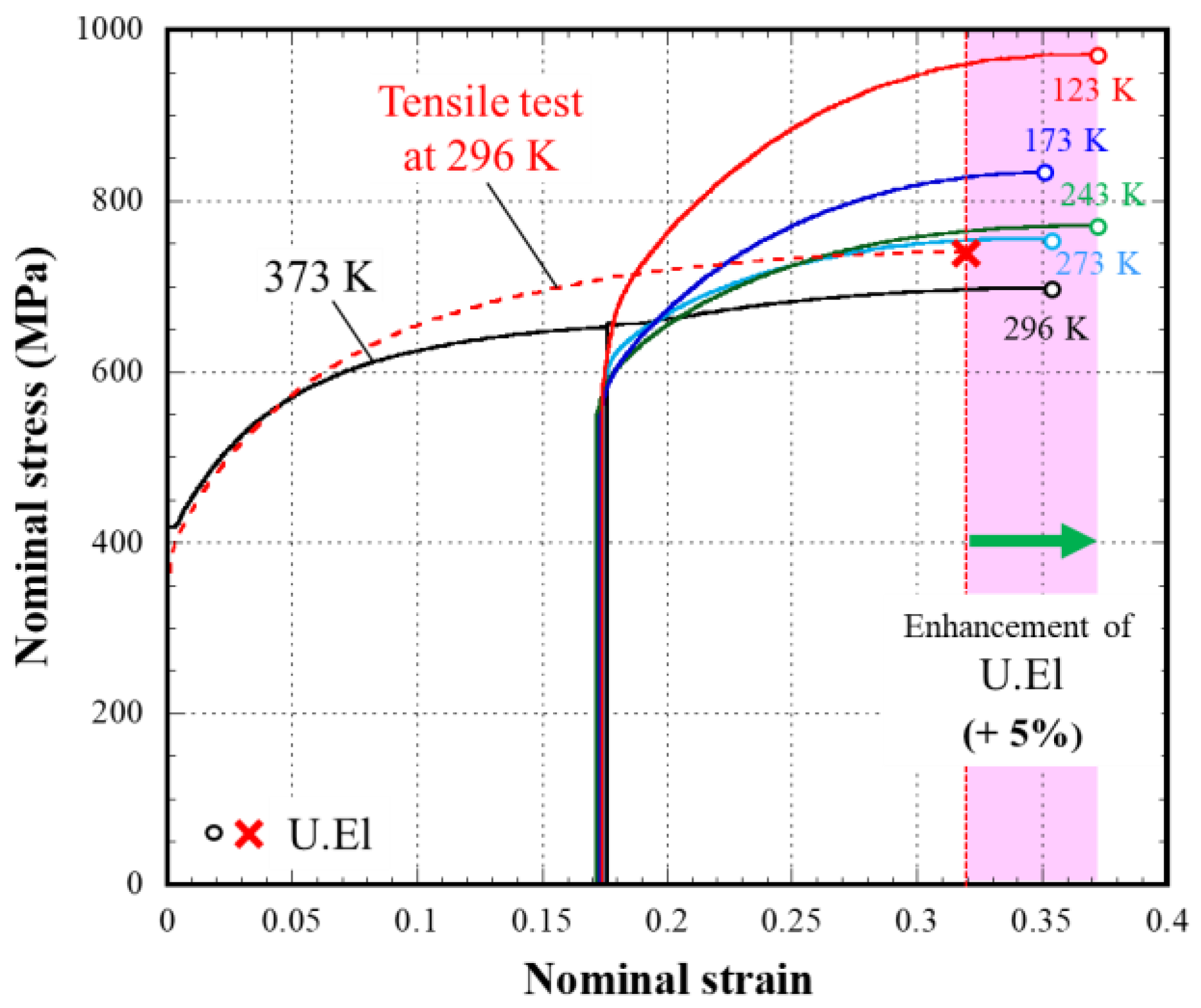
Next, the experimental results obtained from test A are discussed. Figure 6 shows the s–e curves obtained from test A. The figure shows the s–e curves up to the maximum load point and the dashed line shows the s–e curve obtained from the tensile test at 296 K. When the tensile tests were conducted again at various temperatures below 296 K after applying e of about 0.17 at 373 K, U.El became larger than that at 296 K. However, the effect of the reloading temperature on U.El was small, and the difference in U.El between test A and the tensile test at 296 K was approximately only 5%, being independent of the temperature. On the other hand, in the s–e curves reloaded at below 243 K, the elastic limit immediately after reloading was smaller than that at e of about 0.17 at 373 K. The elastic limit seems to decrease due to the transformation strain because the DIMT occurred below the yield strength at temperatures less than 243 K [20,24,25]. Figure 7 shows a comparison of the TS and U.El between test A and the tensile tests at constant deformation temperatures. Here, the TS and U.El obtained from test A are shown as functions of the reloading temperature after tensile deformation at 373 K. The TS at a given temperature was almost the same between test A and the tensile test at constant deformation temperatures. In test A, U.El at below 296 K was improved compared with that in the tensile tests but was almost the same independent of the temperature below 273 K. The difference in U.El between test A and the tensile test became slightly larger at lower temperatures.
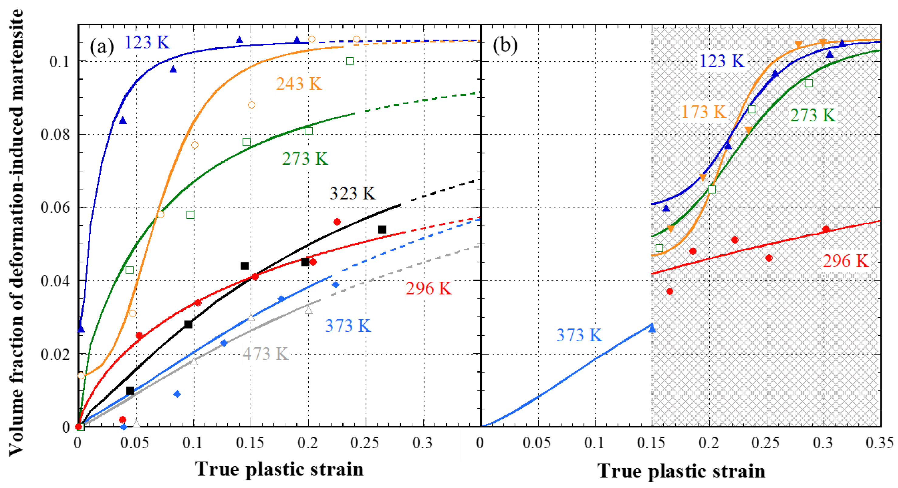
Figure 8 shows Vα′ as a function of ε obtained from the tensile tests at constant deformation temperatures (a) and test A (b). Here, the plots are the calculated results obtained from the X-ray diffraction experiments and the lines are the calculated results obtained by using the following equation by Matsumura et al. [9,10]:
V α = V γ 0 V γ 0 1 + ( k / q ) V γ 0 ε q
where Vγ0 is Vγ before deformation, k is a constant related to the mechanical stability of γR, and q is the strain exponent related to the autocatalytic effect [10]. The values of k and q used in Figure 8 are summarized in Table 1. Vα′ at a given ε increased with a decrease in the deformation temperature in both Figure 8a,b. In Figure 8a, a large amount of γR was transformed to α′ at the early stage of deformation with the decrease in deformation temperature. γR was transformed to α′ at the elastic limit (ε = 0) at 123 and 243 K in Figure 8a. In this time, we confirmed from X-ray diffraction experiments that γR had not transformed to α′ by just cooling to 77 K. At temperatures > 296 K, Vα′ was almost saturated at ε > about 0.2. Regarding 296 and 323 K in Figure 8a, we determined that the DIMT behavior was almost the same. In Figure 8b, the lower the reloading temperature was, the larger the increase in Vα′ became just after the reloading. Such DIMT behavior did not, however, lead to a larger improvement of the U.El in test A, as seen in Figure 6 and Figure 7 [14,15,20]. On the other hand, the difference in Vγ at ε of 0.15 between Figure 8a,b became larger with the decrease in temperature. The DMIT until ε of 0.15 seems to be suppressed in the tensile deformation at 373 K in test A. Because the changes of Vγ from ε of 0.15 to the TS in test A were larger in comparison with the cases of the tensile tests at constant deformation temperatures, U.El in test A became larger with the decrease in the reloading temperature, as seen in Figure 7. The U.El below 273 K in test A were approximately 5% larger than that obtained in the tensile test at 296 K. The reason might be that a large amount of γR transformed into α′ just after the reloading at a lower reloading temperature (Figure 8b). The difference in the U.El between test A and the tensile test at 296 K can almost be explained by the difference in the DIMT behavior. To retain more Vγ up to larger ε is effective to the TRIP effect from the viewpoint of the DIMT of γR [1,8]. However, we confirmed that it was difficult to improve the U.El considerably by conducting test A. Based on the results obtained from test A, we designed test B, in which the deformation temperature was gradually–continuously decreased during tensile deformation, as seen in Figure 1b.

3.3. Enhancement of Uniform Elongation in Test B

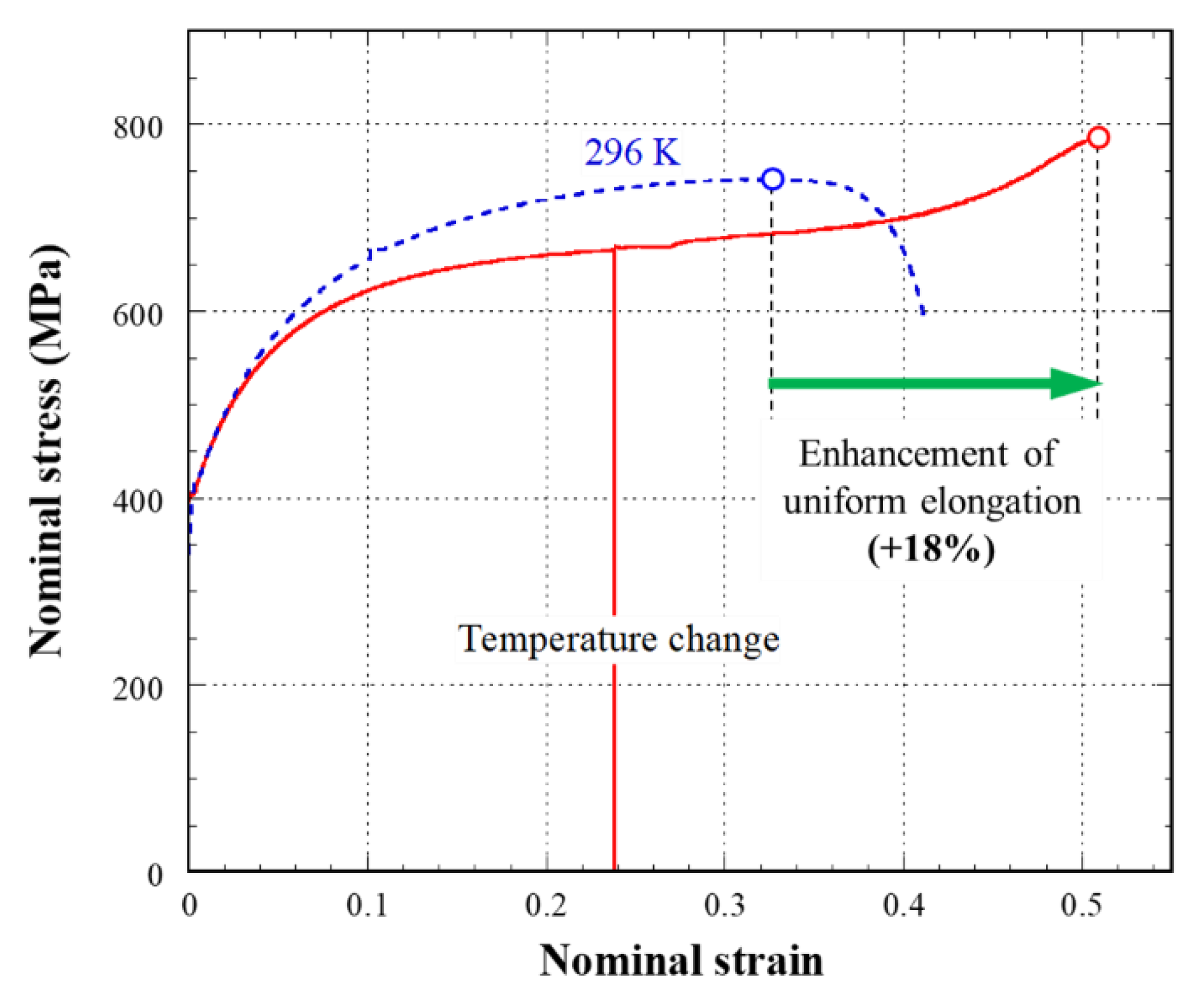
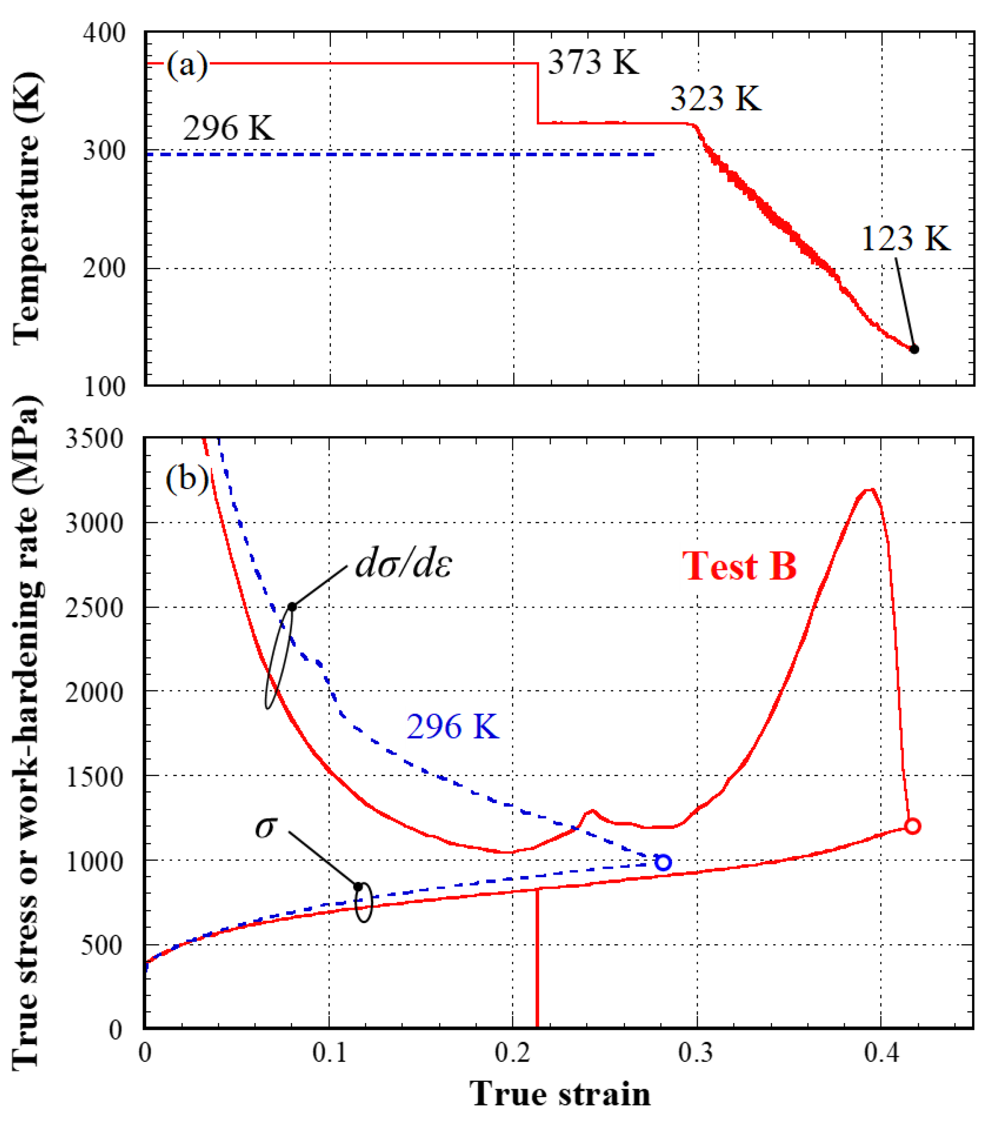
Figure 9 shows the s–e curves obtained from test B and the tensile test at the constant deformation temperature of 296 K. It is noted that the U.El in test B was 51%, approximately 1.5 times larger than that obtained in the tensile test at 296 K. The continuous decrease in the deformation temperature is effective to maximize the TRIP effect, resulting in a great improvement in the U.El. Figure 10 shows the changes in the deformation temperature (a) and σ and / (b) as functions of ε obtained from test B and the tensile test at 296 K. / decreased with the increase in ε in the tensile test at 296 K. However, in test B, / changed in the increasing trend when the temperature continuously decreased from 323 K after ε of about 0.3. Such / behavior is accompanied with the enlargement of ε, satisfying the plastic instability, i.e., the U.El [1,8,26]. It is expected that the DIMT behavior and the deformation behavior of each phase affect the / behavior after ε of 0.3 in test B.
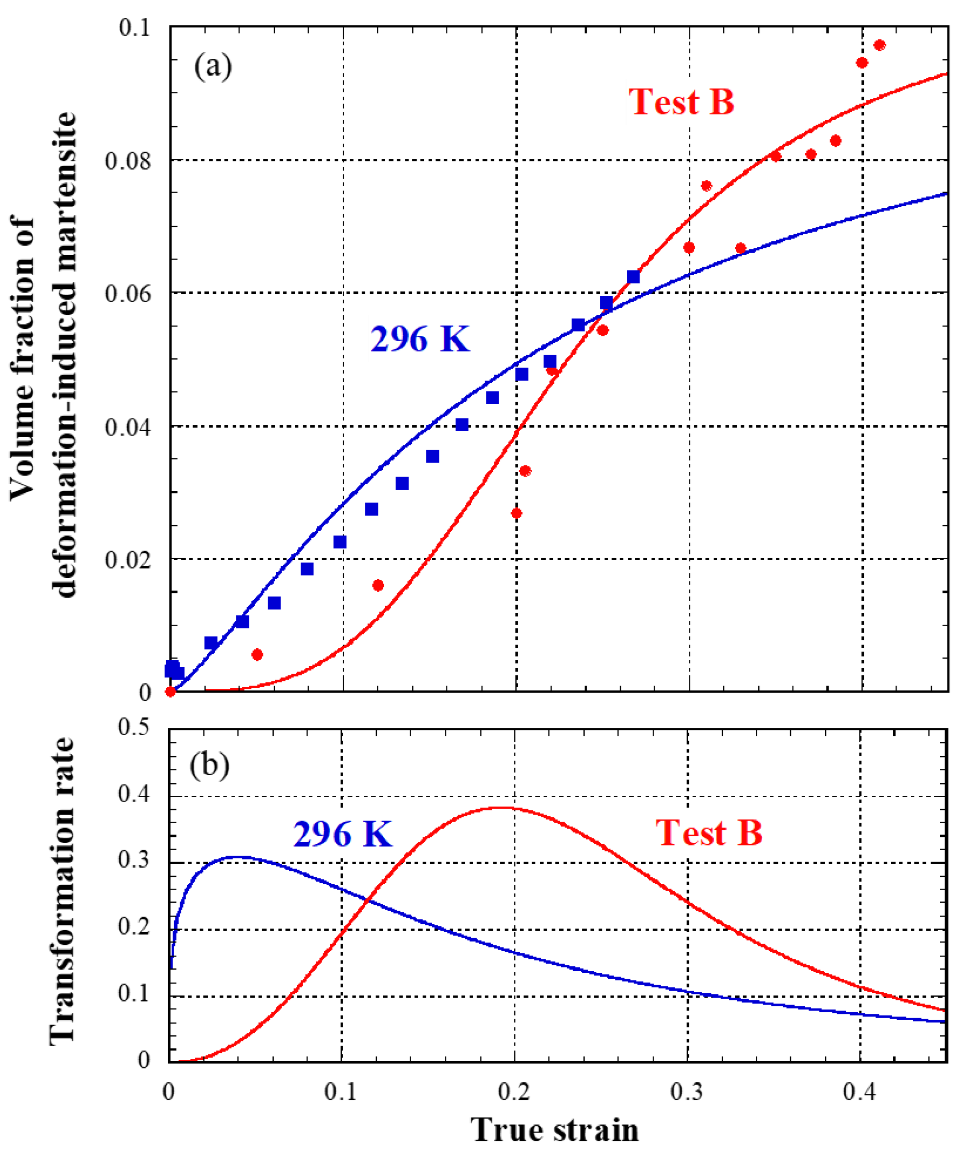
Next, we discuss the DIMT behavior and the tensile deformation behavior of each phase in test B based on the neutron diffraction experiments. Figure 11 shows Vα (a) and the transformation rate (b) as functions of ε in test B and the tensile test at 296 K [7]. The values of k and q in Equation (4) used in Figure 11 are summarized in Table 2. Here, the transformation rate in Figure 11b was calculated by using Equation (4) [9,15,20]. In the tensile test at 296 K, Vα′ monotonically increased from the early stage of tensile deformation, and the maximum transformation rate of about 0.3 was indicated at ε of 0.03, i.e., at the early stage of tensile deformation. On the other hand, in test B, Vα′ was smaller than that in the tensile test at 296 K until ε of about 0.25. Vα′ was larger in test B after ε of 0.25 and almost all of γR was transformed into α′ at the maximum load point. The transformation rate in test B gradually increased and the maximum transformation rate of about 0.4 was indicated at ε of 0.2. As seen in Figure 10, at ε of about 0.2, the deformation temperature decreased from 373 to 323 K and the test specimen was reloaded. Vα′ markedly increased immediately after the reloading, as seen in Figure 8b. Therefore, the maximum transformation rate of 0.4 in test B seems to be associated with the reloading at a lower deformation temperature. The transformation rate in test B decreased with the increase in ε after ε of 0.2, but indicated higher values compared with that in the tensile test at 296 K. This shows that we have succeeded in effectively controlling the DIMT activation or the γR contribution to the TRIP effect up to very large ε [4,10,12,14].
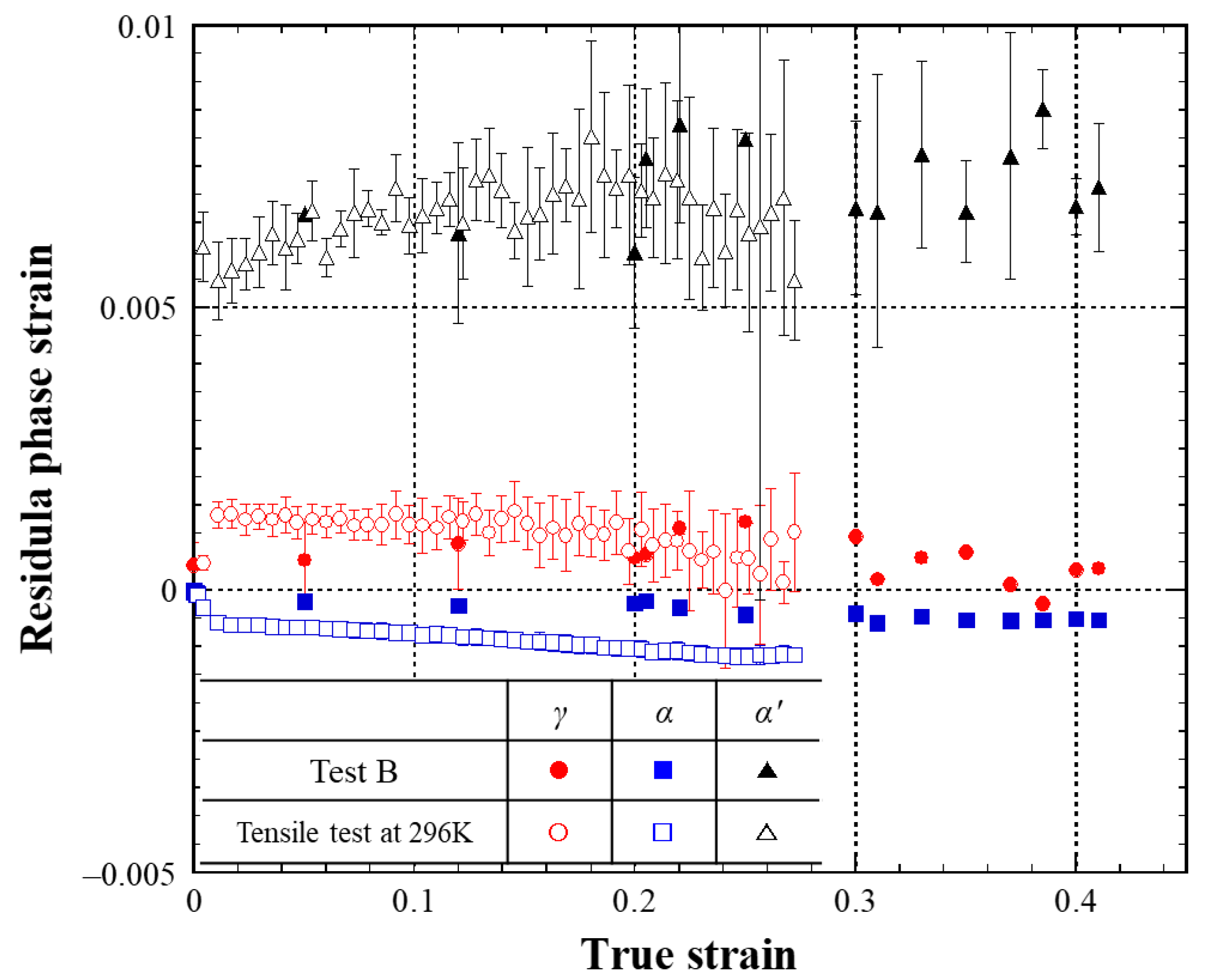
Figure 12 shows ε p h a s e r of the γ, α, and α′ phases as a function of ε in test B and the tensile test at 296 K [7]. Here, the distinctions between ferrite and bainite microstructures in the TRIP steel were difficult because they have the bcc structure and the similar lattice constant. They were assumed to behave as one α phase in this study. In the tensile test at 296 K, ε p h a s e r of α was compressive, and those for γ and α′ were tensile. This is coincident with the experimental results in the previous studies [16,17,27,28]. Immediately after yielding, stress partitioning occurred between γ and α, and the DIMT started [4,7,16,17]. The difference in ε p h a s e r between γ and α became slightly smaller with the increase in ε because ε p h a s e r of γ was decreased at ε > 0.2. On the other hand, in test B, the difference in ε p h a s e r between γ and α was smaller than that in the tensile test at 296 K. After the reloading at ε of about 0.2 at 323 K, ε p h a s e r of γ became larger but was gradually smaller at ε of about 0.3. ε p h a s e r of α′ in test B was almost the same as that in the tensile test at 296 K and increased slightly after ε of 0.3 [4,7,17]. ε p h a s e r of γ and α were different from each other in the comparisons of ε p h a s e r between test B and the tensile test at 296 K. However, it is difficult to discuss the improvement of U.El in test B from only ε p h a s e r because the deformation temperature and the changes of Vγ and Vα′ during tensile deformation are different between the two types of tests [4,17,29].
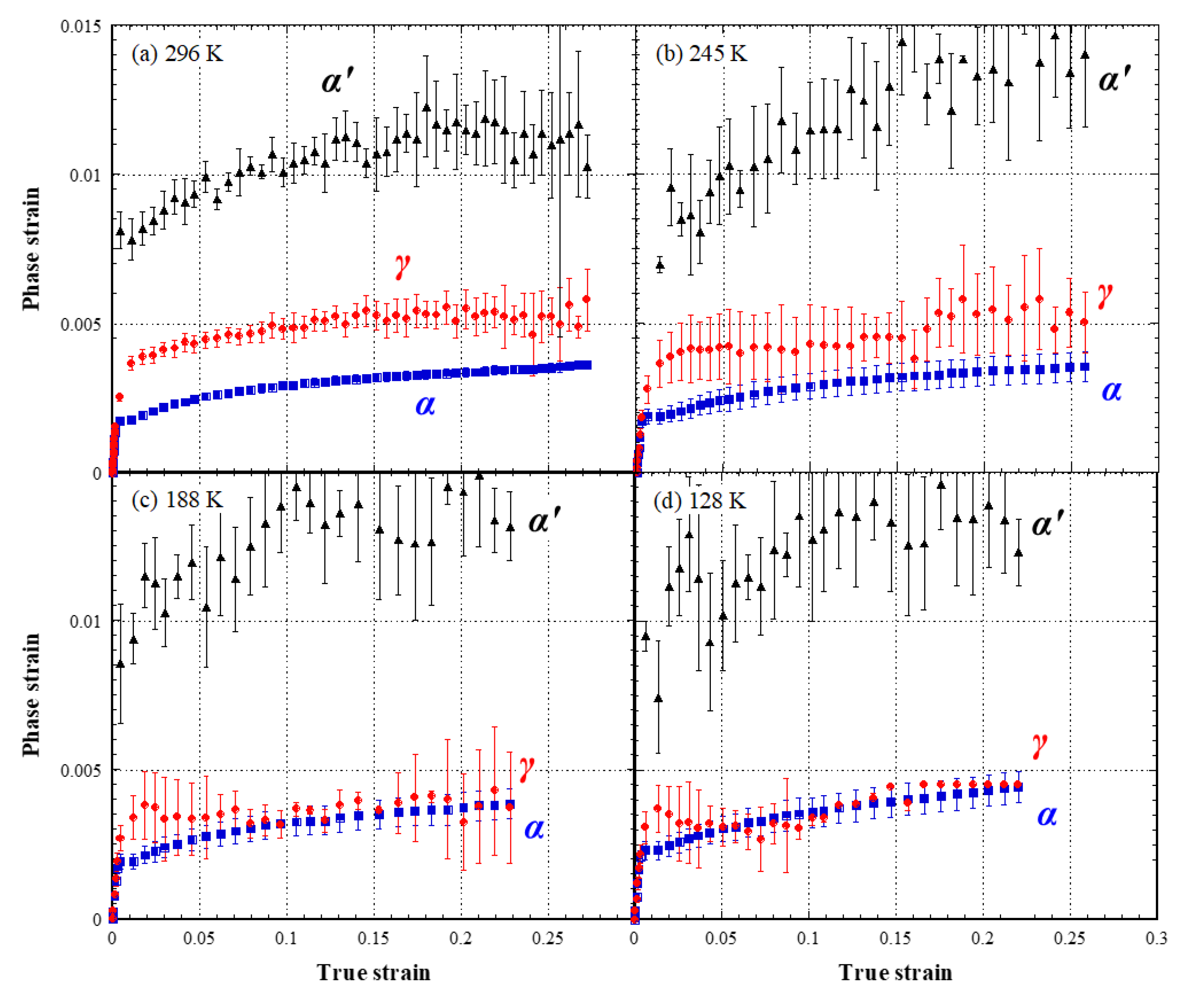
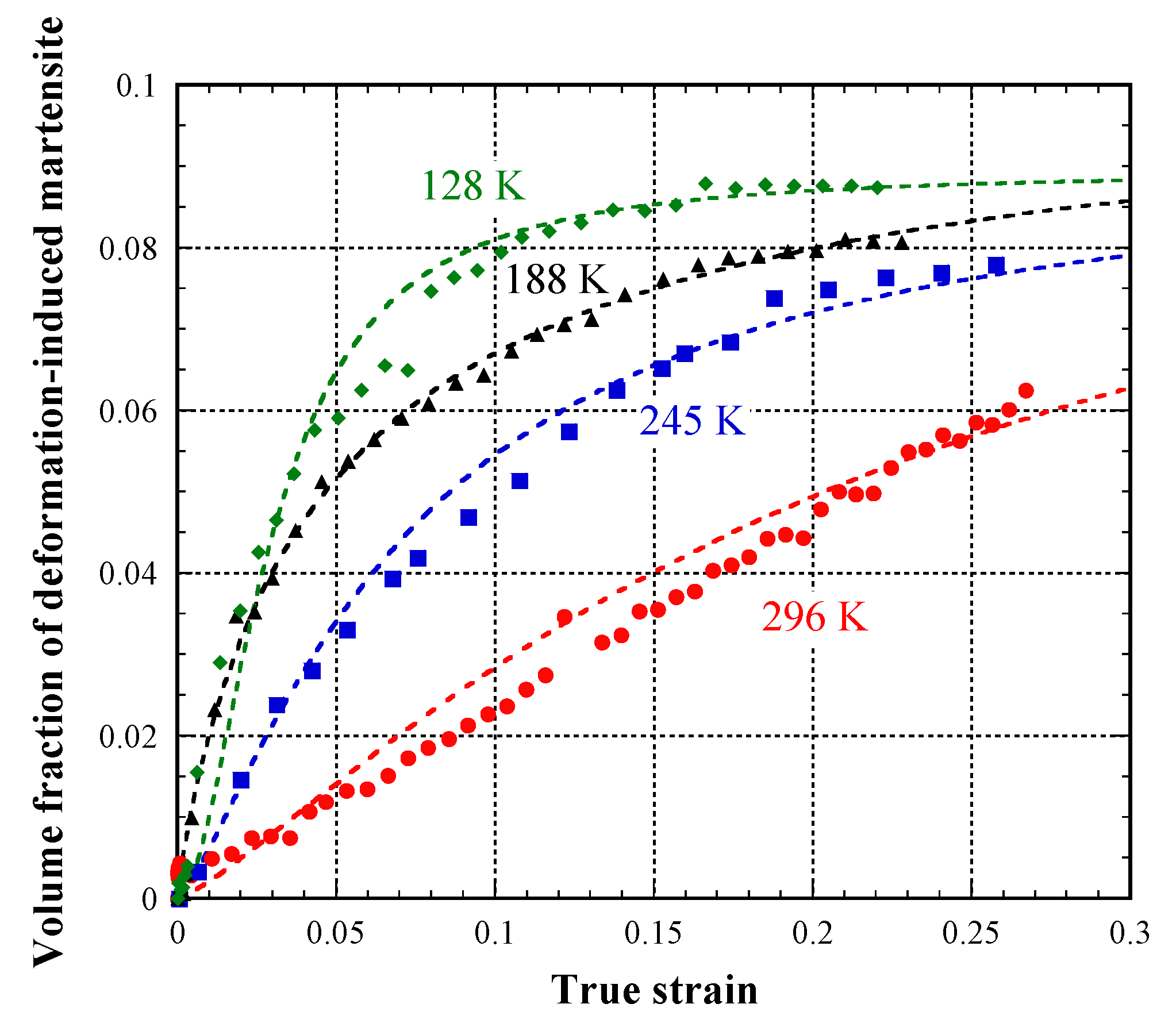
Figure 13 shows the phase strains of γ (εγ), α (εα), and α′ (εα′) as a function of ε obtained by the in situ neutron diffraction experiments during tensile deformation at constant deformation temperatures of 296 K (a) [7], 245 K (b), 188 K (c), and 128 K (d). εα at a given ε became larger with a decrease in the deformation temperature whereas εγ slightly became smaller. εα′ became larger with a decrease in the deformation temperature at ε < 0.15 but that was almost the same as being independent of the deformation temperature at ε > 0.15, except for the data at 296 K. εα′ indicates the largest value among the three phases and the calculated phase stress of α′ is approximately 2–3 GPa in Figure 13 [4,7,17]. Figure 14 shows Vα′ as a function of ε at various deformation temperatures. The dashed lines in Figure 14 are the calculated results by Equation (4), and the values of k and q are summarized in Table 2. Vα′ at a given ε increased with a decrease in the deformation temperature. The larger γ was transformed into α′ at the early stage of tensile deformation with the lower deformation temperature [14,15,17,20]. At 128, 188, and 245 K, the increase of Vα′ was almost slowed down after ε > about 0.15. Judging from Figure 13 and Figure 14, εγ and εα′ seem to be associated with their changes of volume fraction. εα′ is smaller when Vα′ is small. In Figure 13, εα′ at ε < 0.15 was larger with an increase in Vα′ due to the decrease in the deformation temperature [17,23]. At ε > 0.15, the increase of Vα′ was almost stagnated except for 296 K and the Vα′ was about 0.08 or more. Thus, εα′ at ε > 0.15 in Figure 13b–d were almost the same, independent of the deformation temperature. On the other hand, εγ at ε > 0.1 became slightly smaller, with a decrease in the deformation temperature because of decreasing the Vγ. εγ, εα, and εα′ of the TRIP steel at lower temperatures were also reported by Yamashita et al. [17]. They studied in situ neutron diffraction experiments during tensile deformation at various temperatures between 134 and 293 K using a TRIP-aided multi-microstructure steel obtained from a 0.31C steel having a Vγ0 of 17.9%. The difference between εγ and εα was also decreased with a decrease in the deformation temperature, and εγ was smaller than εα at temperatures below 223 K [17]. The effect of the deformation temperature on the phase strain in Figure 13 seems to be associated with ε p h a s e r in Figure 12. The difference of the phase strains between γ and α at a given ε became smaller with a decrease in the deformation temperature. The phase strain of α′ at a given ε increased as the deformation temperature decreased. Those temperature dependences on the phase strains were almost coincident with ε p h a s e r of the γ, α, and α′ in Figure 12. ε p h a s e r of α′ increased with the increasing of Vα′, which is similar to εα′ in Figure 13. The difference in ε p h a s e r between γ and α at ε < 0.2 was smaller in test B because the deformation temperature was higher and Vα′ was smaller in comparison with the tensile test at 296 K. At ε > 0.3, the deformation temperature was lowered during tensile deformation and Vα′ increased with the higher transformation rate, which seem to lead to the decrease in εγ. εα decreased little by the decrease in the deformation temperature in contrast to the case of tensile test at 296 K. The changes of ε p h a s e r of the γ, α, and α′ phases in test B seem to be complicated because both Vα′ and the deformation temperature are changed during tensile deformation.
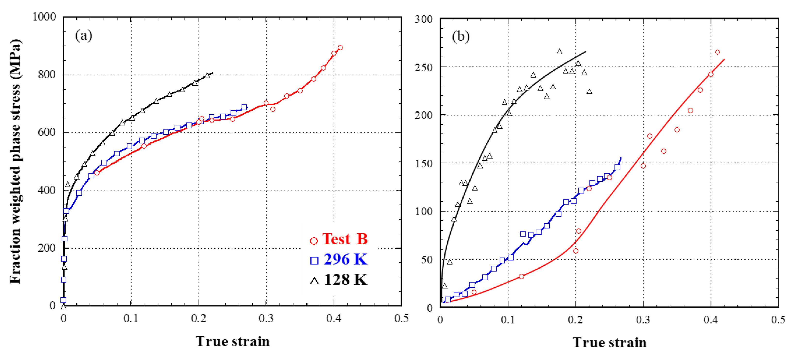
Next, we try to discuss the improvement of U.El in the test B from ε p h a s e r and the change of volume fractions, including the DIMT behavior. Here, we focused on a fraction weighted phase stress [17,30,31]. The σ at a given ε can be calculated as the sum of fraction-weighted phase stresses by the following stress equilibrium approach [17,30,31],
σ = Vα σα + Vγ σγ + Vα’ σα’
where σα, σγ, and σα′ are the phase stresses for α, γ, and α′ phases, respectively. Vi σi (i = α, γ, and α′) means the fraction-weighted phase stress for each phase. From the relationship between ε p h a s e r and σ, the phase strain at a given σ can be estimated by using the slope in the elastic regime [26]. σα, σγ, and σα′ are calculated by using the following equation,
σi = Ei εi
where σi is phase stress, εi phase strain, and Ei Young’s modulus (i = α, γ, and α′), respectively. Figure 15 shows Vα σα (a) and Vα′ σα′ (b) as a function of ε in the tensile tests at the constant deformation temperatures of 296 and 128 K, and test B. The Vα σα of test B was slightly smaller in that of the tensile test at 296 K, and its change at ε > 0.3 became larger because the deformation temperature was decreasing from ε of 0.3. The change of Vα′ σα′ in Figure 15b was closely associated with the Vα′, as seen in Figure 11 and Figure 14. This means the effect of DIMT on Vα′ σα′ is very large. Table 3 represents the fraction-weighted phase stresses and σ at the maximum load point in test B and the tensile test at 296 K. The differences of Vα σα, Vγ σγ, and Vα′ σα′ between test B and the tensile test at 296 K were approximately 200 MPa, 50 MPa, and 100 MPa, respectively. The difference of the measured σ at the maximum load point was about 200 MPa, as seen in Figure 10b and Table 3. The calculated results using Vi σi seem to be approximately coincident with the measured σ, even though the difference between the calculated σ by Equation (5) and the measured σ should be considered.
Let us discuss the improvement of the U.El in test B using the changes of Vi σi against ε. The change in the Vi σi affected the change in σ, which is therefore related to the / [8,23]. The increase in Vi σi at larger ε will lead to the larger /, as also seen in Figure 10b. The Vα σα and Vα′ σα′ at the maximum load point for the tensile test at the constant deformation temperature of 128 K indicated almost the same values with those in test B. However, the values were achieved at much lower ε than in test B. The changes Vα σα and Vα′ σα′ in the tensile test at 128 K were larger at ε < 0.2, whereas those in test B were larger at the latter part of tensile deformation of ε > 0.3. The increase of the work-hardening rate at ε > 0.3 for test B is associated with Vα σα and Vα′ σα′. Therefore, it is concluded that the improvement of the U.El in test B are associated with the increase of Vα σα due to the decrease in deformation temperature and Vα′ σα′ affected by the DIMT behavior. By gradually decreasing the deformation temperature during plastic deformation in test B, the ductile-to-brittle transition of α might be controlled to maintain a slow increase in the Vα σα in the beginning of the deformation, and at the same time, the effective activation of DIMT might be increased gradually to transform almost all γR to α′. It is important that both Vα σα and Vα′ σα′ increase at the larger ε to obtain the better U.El in test B.
The decreasing of the deformation temperature during tensile deformation, such as in test B, leads to the continuous DIMT up to larger ε, and the effect of high strength α′ on the TRIP effect becomes larger at the larger ε. The decreasing of the deformation temperature also contributed to the increase of σα. Those played a function in the increase of / at larger ε and the improvement of the U.El in test B. The α phase, whose volume fraction is about 80% in the TRIP-aided multi-microstructure steels, affects the mechanical properties and s–e curves in the TRIP steels [3,4,9,16]. As seen in Figure 11 and Figure 13a, in the tensile test at 296 K, the increases of Vα′ and εα′ were almost saturated at ε > about 0.2 [4,16,17]. In order to obtain better U.El due to the TRIP effect, phases other than α′ which contribute to high strength are necessary to maintain large work hardening [4,32]. It is found from Figure 13 and Figure 15 that the α phase has a key role in test B. It is concluded that not only the DIMT behavior but also the role of α, which plays a crucial role in maintaining high strength, instead of α′ at a larger ε are very important in the efficient TRIP effect.

4. Conclusions

In this study, we conducted tensile tests in which the deformation temperature was decreased during the tensile deformation in order to investigate the DIMT conditions required for an efficient TRIP effect. The following conclusions were obtained.
  • In the tensile tests, in which the test specimens were reloaded at lower temperatures after being unloaded once, the improvement of U.El was about 5% and almost independent of the reloading temperature. This is because a large amount of γR was transformed into α′ just after the reloading at lower temperatures.
  • On the other hand, when the deformation temperature was decreased continuously during the tensile deformation, a very large U.El of 51% was obtained. This value was about 1.5 times larger than that obtained in the tensile test at room temperature.
  • In terms of the DIMT behavior in the temperature change test, Vα′ was smaller in the early stage of deformation and larger after ε of 0.25 compared with that in the tensile test at 296 K. Almost all of γR was transformed into α′ at the maximum load point. The transformation rate gradually increased and the maximum transformation rate of about 0.4 was indicated at ε of about 0.2.
  • The neutron diffraction experiments in the temperature change test revealed that not only the DIMT behavior but also the deformation behavior of γ, α, and α′ are important factors in the TRIP effect. The α phase contributed to maintain high strength, instead of α′ at a larger ε in addition to the DIMT behavior, and played an important role in the enhancement of U.El.

Author Contributions

Conceptualization, N.T.; methodology, N.T.; investigation, N.T. and S.H.; data curation, N.T. and S.H.; writing—original draft preparation, N.T.; writing—review and editing, N.T. and S.H.; supervision, N.T. and S.H. All authors have read and agreed to the published version of the manuscript.

Funding

This research received no external funding.

Data Availability Statement

Data presented in this article are available at request from the corresponding author.

Acknowledgments

The authors are grateful to K. Aizawa and T. Kawasaki of J-PARC Center, Japan Atomic Energy Agency for their help and valuable discussions. The neutron diffraction experiments were performed at the J-PARC/MLF beamline in JAEA (proposal no. 2015A044).

Conflicts of Interest

The authors declare no conflict of interest.

References

  1. Angel, T. Formation of martensite in austenitic stainless steels. J. Iron Steel Inst. 1954, 177, 165–174. [Google Scholar]
  2. Bouquerel, J.; Verbeken, K.; De Cooman, B.V. Microstructure-based model for the static mechanical behaviour of multiphase steels. Acta Mater. 2006, 54, 1443–1456. [Google Scholar] [CrossRef]
  3. Blonde, R.; Jimenez-Melero, E.; Zhao, L.; Wright, J.P.; Bruck, E.; van der Zwaag, S.; van Dijk, N.H. High-energy X-ray diffraction study on the temperature-dependent mechanical stability of retained austenite in low-alloyed TRIP steels. Acta Mater. 2012, 60, 565–577. [Google Scholar] [CrossRef]
  4. Tsuchida, N.; Tanaka, T.; Toji, Y. Analysis of tensile deformation behavior by in situ neutron diffraction experiments of a 1 GPa-grade TRIP steel with high elongation. ISIJ Int. 2020, 60, 1329–1337. [Google Scholar] [CrossRef]
  5. Sugimoto, K.; Kobayashi, M.; Hashimoto, S. Ductility and strain-induced transformation in a high-strength transformation-induced plasticity-aided dual-phase steel. Metall. Trans. A 1992, 23, 3085–3091. [Google Scholar] [CrossRef]
  6. Varshney, A.; Sangal, S.; Kundu, S.; Mondal, K. Super strong and highly ductile low alloy multiphase steels consisting of bainite, ferrite and retained austenite. Mater. Des. 2016, 95, 75–88. [Google Scholar] [CrossRef]
  7. Harjo, S.; Tsuchida, N.; Abe, J.; Gong, W. Martensite phase stress and the strengthening mechanism in TRIP steel by neutron diffraction. Sci. Rep. 2017, 7, 15149. [Google Scholar] [CrossRef] [PubMed]
  8. Tsuchida, N.; Tomota, Y. A micromechanic modeling for transformation induced plasticity in steels. Mater. Sci. Eng. A 2000, 285, 345–352. [Google Scholar] [CrossRef]
  9. Matsumura, O.; Sakuma, Y.; Ishii, Y.; Zhao, J. Effect of retained austenite on formability of high strength sheet steels. ISIJ Int. 1992, 32, 1110–1116. [Google Scholar] [CrossRef] [Green Version]
  10. Matsumura, O.; Sakuma, Y.; Takechi, H. TRIP and its kinetics aspects in austempered 0.4C-1.5Si-0.8Mn steel. Scr. Mater. 1987, 21, 1301–1306. [Google Scholar] [CrossRef]
  11. Mukherjee, M.; Mohanty, O.N.; Hashimoto, S.; Hojo, T.; Sugimoto, K. Strain-induced transformation behaviour of retained austenite and tensile properties of TRIP-aided steels with different matrix microstructure. ISIJ Int. 2006, 46, 316–324. [Google Scholar] [CrossRef] [Green Version]
  12. Tsuchida, N.; Osaki, K. Effect of strain rate on TRIP effect in a 0.2C-1.5Si-1.2Mn steel. Tetsu-to-Hagane 2013, 99, 524–531. (In Japanese) [Google Scholar] [CrossRef] [Green Version]
  13. Tamura, I. Deformation-induced martensitic transformation and transformation-induced plasticity in steels. Met. Sci. 1982, 16, 245–253. [Google Scholar] [CrossRef]
  14. Tsuchida, N.; Morimoto, Y.; Tonan, T.; Shibata, Y.; Fukaura, K.; Ueji, R. Stress-induced martensitic transformation behaviors at various temperatures and their TRIP effects in SUS304 metastable austenitic stainless steel. ISIJ Int. 2011, 51, 124–129. [Google Scholar] [CrossRef] [Green Version]
  15. Tsuchida, N.; Yamaguchi, Y.; Morimoto, Y.; Tonan, T.; Takagi, Y.; Ueji, R. Effects of temperature and strain rate on TRIP effect in SUS301L metastable austenitic stainless steel. ISIJ Int. 2013, 53, 1881–1887. [Google Scholar] [CrossRef] [Green Version]
  16. Tomota, Y.; Tokuda, H.; Adachi, Y.; Wakita, M.; Minakawa, N.; Moriai, A.; Morii, Y. Tensile behavior of TRIP-aided multi-phase steels studied by in situ neutron diffraction. Acta Mater. 2004, 52, 5737–5745. [Google Scholar] [CrossRef]
  17. Yamashita, T.; Morooka, S.; Harjo, S.; Kawasaki, T.; Koga, N.; Umezawa, O. Role of retained austenite in low alloy steel at low temperature monitored by neutron diffraction. Scripta Mater. 2020, 117, 6–10. [Google Scholar] [CrossRef]
  18. Tsuchida, N.; Nagahisa, N.; Harjo, S. Room-temperature creep tests under constant load on a TRIP-aided multi-microstructure steel. Mater. Sci. Eng. A 2017, 700, 631–636. [Google Scholar] [CrossRef]
  19. Lamari, M.; Allain, S.Y.P.; Geandier, G.; Hell, J.-C.; Perlade, A.; Zhu, K. In situ determination of phase stress states in an unstable medium manganese duplex steel studied by high-energy X-ray diffraction. Metals 2020, 10, 1335. [Google Scholar]
  20. Tsuchida, N.; Tanaka, T.; Toji, Y. Effect of deformation temperature on mechanical properties in 1-GPa-grade TRIP steels with different retained austenite morphologies. ISIJ Int. 2021, 61, 564–571. [Google Scholar] [CrossRef]
  21. Saleh, A.A.; Pereloma, E.V.; Clausen, B.; Brown, D.W.; Tomé, C.N.; Gazder, A.A. On the evolution and modelling of lattice strains during the cyclic loading of TWIP steel. Acta Mater. 2013, 61, 5247–5262. [Google Scholar] [CrossRef] [Green Version]
  22. Han, H.N.; Suh, D.-W. A model for transformation plasticity during bainite transformation of steel under external stress. Acta Mater. 2003, 51, 4907–4917. [Google Scholar] [CrossRef]
  23. Tsuchida, N.; Ueji, R.; Inoue, T. Effect of temperature on stress–strain curve in SUS316L metastable austenitic stainless steel studied by in situ neutron diffraction experiments. ISIJ Int. 2021, 61, 632–640. [Google Scholar] [CrossRef]
  24. Vasiliakos, A.N.; Papamantellos, K.; Haidemenopoulos, G.N.; Bleck, W. Experimental determination of the stability of retained austenite in low alloy TRIP steels. Steel Res. 1999, 70, 466–471. [Google Scholar] [CrossRef]
  25. Bolling, G.F.; Richman, R.H. The plastic deformation-transformation of paramagnetic F.C.C. Fe-Ni-C alloys. Acta Metall. 1970, 18, 673–681. [Google Scholar] [CrossRef]
  26. Tsuchida, N.; Ishimaru, E.; Kawa, M. Role of deformation-induced martensite in TRIP effect of metastable austenitic steels. ISIJ Int. 2021, 61, 556–563. [Google Scholar] [CrossRef]
  27. Jacques, P.J.; Furnemont, Q.; Godet, S.; Pardoen, T.; Conlon, K.T.; Delannay, F. Micromechanical characterisation of TRIP-assisted multiphase steels by in situ neutron diffraction. Philos. Mag. 2006, 86, 2371–2392. [Google Scholar] [CrossRef]
  28. Muránsky, O.; Šittner, P.; Zrník, J.; Oliver, E.C. In situ neutron diffraction investigation of the collaborative deformation–transformation mechanism in TRIP-assisted steels at room and elevated temperatures. Acta Mater. 2008, 56, 3367–3379. [Google Scholar] [CrossRef]
  29. Dutta, A.; Ronge, D.; Sandlöbes, S.; Raabe, D. Strain partitioning and strain localization in medium manganese steels measured by in situ microscopic digital image correlation. Materialia 2019, 5, 100252. [Google Scholar] [CrossRef]
  30. Harjo, S.; Kubota, S.; Gong, W.; Kawasaki, T.; Gao, S. Neutron diffraction monitoring of ductile cast iron under cyclic tension–compression. Acta Mater. 2020, 196, 584–594. [Google Scholar] [CrossRef]
  31. Tomota, Y.; Lukáš, P.; Neov, D.; Harjo, S.; Abe, Y.R. In situ neutron diffraction during tensile deformation of a ferrite-cementite steel. Acta Mater. 2003, 51, 805–817. [Google Scholar] [CrossRef]
  32. Asoo, K.; Tomota, Y.; Harjo, S.; Okitsu, Y. Tensile behavior of a TRIP-aided ultra-fine grained steel studied by neutron diffraction. ISIJ Int. 2011, 51, 145–150. [Google Scholar] [CrossRef] [Green Version]
Figure 1. Schematic illustrations about test A (a) and B (b).
Metals 11 02053 g001
Figure 2. EBSD phase mapping image (a) and orientation color map (b) in the 0.2C TRIP steel.
Metals 11 02053 g002
Figure 3. Nominal stress–nominal strain curves of the 0.2C TRIP steel obtained by tensile tests at various deformation temperatures.
Metals 11 02053 g003
Figure 4. 0.2% proof strength, tensile strength, and uniform elongation as a function of temperature in the 0.2C TRIP steel.
Metals 11 02053 g004
Figure 5. True stress (σ) and work-hardening rate (/) as a function of true strain at various deformation temperatures.
Metals 11 02053 g005
Figure 6. Nominal stress–nominal strain curves obtained by test A. Here, the nominal stress–nominal strain curve at 296 K is also shown as a dashed line.
Metals 11 02053 g006
Figure 7. Tensile strength and uniform elongation as a function of deformation temperature obtained by test A and the tensile tests. Here, the temperature of test A means the reloading temperature after tensile deformation at 373 K.
Metals 11 02053 g007
Figure 8. Volume fraction of deformation-induced martensite as a function of true strain obtained by the tensile tests at various deformation temperatures (a) and test A (b).
Metals 11 02053 g008
Figure 9. Nominal stress–nominal strain curves obtained by test B and the tensile test at 296 K.
Metals 11 02053 g009
Figure 10. Deformation temperature (a) and true stress (σ) or work-hardening rate (/) (b) as functions of true strain obtained by test B and the tensile test at 296 K.
Metals 11 02053 g010
Figure 11. Volume fraction of deformation-induced martensite (a) and transformation rate by using Equation (4) (b) as a function of true strain obtained by test B and the tensile test at 296 K [7].
Metals 11 02053 g011
Figure 12. Residual phase strains of austenite (γ), ferrite (α), and deformation-induced martensite (α′) phases as functions of true strain obtained by test B and the tensile test at 296 K [7].
Metals 11 02053 g012
Figure 13. Phase strains of austenite (γ), ferrite (α), and deformation-induced martensite (α′) phases as functions of true strain obtained by in situ neutron diffraction experiments during tensile deformation at 296 K (a) [7], 245 K (b), 188 K (c), and 128 K (d).
Metals 11 02053 g013
Figure 14. Volume fraction of deformation-induced martensite as a function of true strain obtained by in situ neutron diffraction experiments during tensile deformation at 296 K [7], 245 K, 188 K, and 128 K. Here, the dashed lines are calculated by using Equation (4).
Metals 11 02053 g014
Figure 15. Calculated fraction-weighted phase stresses for ferrite phase (a) and deformation-induced martensite one (b) as a function of true strain in test B, the tensile tests at 296 K and 128 K.
Metals 11 02053 g015
Table 1. Values of k and q in Equation (4) in the 0.2C TRIP steel at various deformation temperatures.
Temperature (K)(a) Tensile Test(b) Test A
kqkq
1236.42 × 1042.1323.14 × 1089.54
1732.90 × 101012.2
2432.61 × 1053.495
273197.21.0912.89 × 1066.83
29617.870.74030.121.195
32380.971.291
37356.321.32856.321.328
47332.171.154
Table 2. Values of k and q in Equation (4) in Figure 11a and Figure 14.
Conditionkq
Tensile test296 K77.91.26
245 K425.91.31
188 K120.10.884
128 K15,4071.88
Test B2493.43.1
Table 3. Calculated fraction-weighted phase stresses and true stress at the maximum load point in test B and the tensile test at 296 K.
Stress(a) Test B(b) Tensile Test at 296 K
Vα σα895687
Vγ σγ055
Vα′ σα′265155
Calculated σ by Equation (5)1160897
Measured σ1182960
Publisher’s Note: MDPI stays neutral with regard to jurisdictional claims in published maps and institutional affiliations.