1. Introduction
Distortion, residual stresses, and hot cracks are decisive quality characteristics of cast parts and, depending on their characteristics, facilitate the need for additional finishing steps and rejects. Therefore, the reduction of these defects by a suitable component design and process control is of great interest for a cost-efficient production. In casting processes, these characteristics are assumed to be the result of a combination of solidification shrinkage, which is paired with the respective local self-feeding and the geometric constraint imposed by the mold on the component. In gravity die casting with thermally well conducting metal molds with a high rigidity, the manipulation of solidification through local control of the heat balance appears to be a suitable measure for reducing the above-mentioned quality-reducing variables.
The work presented here was carried out within the framework of the Collaborative Research Centre “Precision Melt Engineering”. The long-term goal of this sub-project, on which the work presented here is based on, is to improve component precision in permanent mold casting by creating a knowledge base in the areas of distortion and hot cracking, and furthermore, the development of corresponding concepts for their prediction, influencing, and minimization. The heat transfer coefficient (HTC) between mold and component, which has already been considered as a possible major influencing factor, was analyzed in this project in several separate studies [
1,
2,
3]. In addition to these primarily experimental studies, in closely related subprojects, the working group is developing numerical methods to advance the coupled thermomechanical simulation on both the macroscale and the microscale [
4,
5]. An algorithm for optimizing the cooling channel layout to the local cooling requirements in plastic injection molding is developed in another sub-project. This is based on the hypothesis that a homogeneously solidifying component develops the lowest distortion [
6]. This approach, originally developed for plastics in injection molding, was transferred to metal casting in a numerical framework and its applicability was evaluated. A recognizable potential became apparent as well as limitations in transferability, which are to be expected due to strongly differing thermophysical material properties between plastics and metals [
7].
Various aspects of the underlying research work have already been addressed in the past: for example, the topic of in-situ measurements of the solidification shrinkage and the resulting forces on the mold for aluminum in sand casting [
8,
9]. Related investigations of the solidification shrinkage of aluminum alloys in permanent graphite molds were carried out [
10], and the results were compared with numerical simulations [
11]. The common feature in these studies was the “T” shape design of the specimen, with one side fixed in the mold in a form-fitting manner and the shrinkage or the force caused by this measured on the other side. For steel casting in sand molds, comparable methods were used [
12] and extended to the in-situ measurement of the resulting distortion as the opening width of a “U” and also compared with simulations [
13]. Component distortion and various possible criteria for its objective evaluation were considered purely on the basis of simulations [
14,
15] and compared with experimental results [
16]. An investigation on the development of distortion and residual stresses in aluminum high pressure die casting for different alloys and geometries both numerically and experimentally was carried out [
17]. It was found that the influence of the heat balance in the mold and after demolding has a large influence on the final distortion. Further, it was stated that the documented knowledge base on the occurrence of component distortion in permanent mold casting is not very pronounced. The above experimental work on gravity die casting only considers shrinkage (mainly one-dimensional) and not the resulting distortion of the part due to mold constraints. In contrast, the studies in high pressure die casting consider geometrically highly complex production parts, where the interactions between thermal and mechanical boundary conditions are not well understood so far (such as different contact conditions). This offers a starting point for investigating the influences on part distortion in isolation and later with their interactions in a mold specially designed for this purpose.
The possibilities of influencing the local heat balance through conformal cooling channels by exploiting the possibilities of generatively manufactured mold modules were considered for high pressure die casting [
18]. Here, the mold insert of the inner contour for a zinc alloy casting was produced by selective laser melting (SLM) and compared with conventional mold inserts. The focus here was on reducing the cycle time and decreasing the porosity, both of which could be improved using conformal cooling channels. Considering the advancing possibilities of generative manufacturing of mold modules with integration of conformal cooling channels, corresponding guidelines for their use in the development process for new molds have already been presented [
19]. Therefore, their use is to be regarded as relevant for the permanent casting processes in the future.
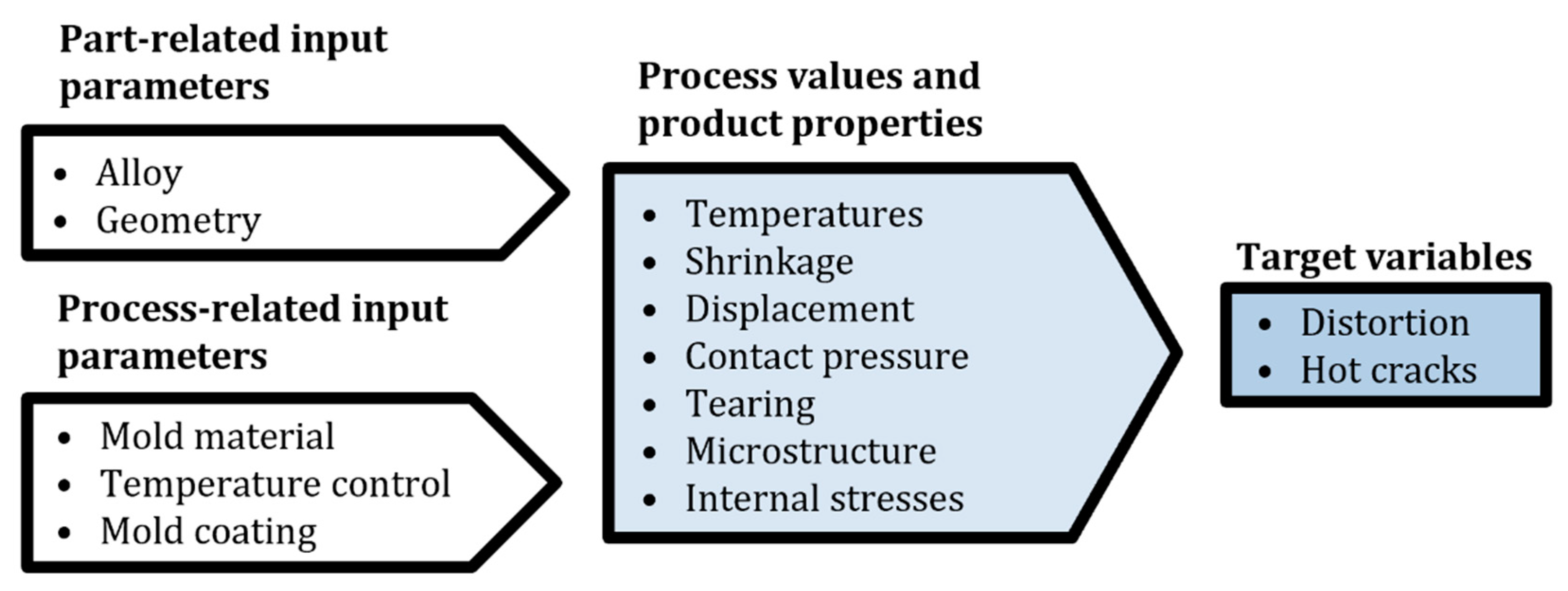
Based on this, the input parameters that can be influenced are divided into component-related and process-related parameters. The target parameters are component distortion and hot cracking. In between, there are variables that can be measured in-situ or later on in the component, which can explain the corresponding relationships and close the causal chain between input parameters and target variables, as can be seen in
Figure 1.
Based on this, the test setup presented here was developed to investigate the deformation and the influences of the above input parameters. The following sub-objectives were defined for the development process:
The test specimen geometry should allow for simple measurability of the resulting component distortion;
In addition to the distortion-relevant area, another area with the possibility of free contraction must be provided in the component for comparison reasons;
There should be a relatively easy possibility of modifying the mold for different geometries, locally different mold materials, temperature control solutions, etc.;
Clearly defined directions and areas of heat extraction must be ensured in the mold;
The integration of variably positionable thermocouples and the possibility of in-situ recording of relative movements between mold and casting as well as the attempt to locally measure the force acting on the component due to in-mold constraints must be implemented;
A convenient procedure for the experimental work to investigate the influences on the distortion in the developed setup should be derived.
4. Discussion
During commissioning of the setup, it turned out that the handling and especially the precise positioning of the thermocouples through the sand cover caused considerable difficulties and could not be achieved without sand abrasion entering the cavity. After cooling to room temperature, the casting was easy to remove without much resistance except for a slight shrinkage to the core module inside. This prevents further plastic deformations of the test specimen during demolding. The measurement of the distortion could be achieved by the simple use of a caliper at various points of the opening of the “U”, and the measurement accuracy was less than 0.05 mm. One to two castings per day could be achieved during the series of tests depending on the number of measuring devices installed. The limiting time factor was cooling down to room temperature and the renewal of the measurement devices, as the thermocouples and quartz rods protruding into the melt must be replaced after each casting.
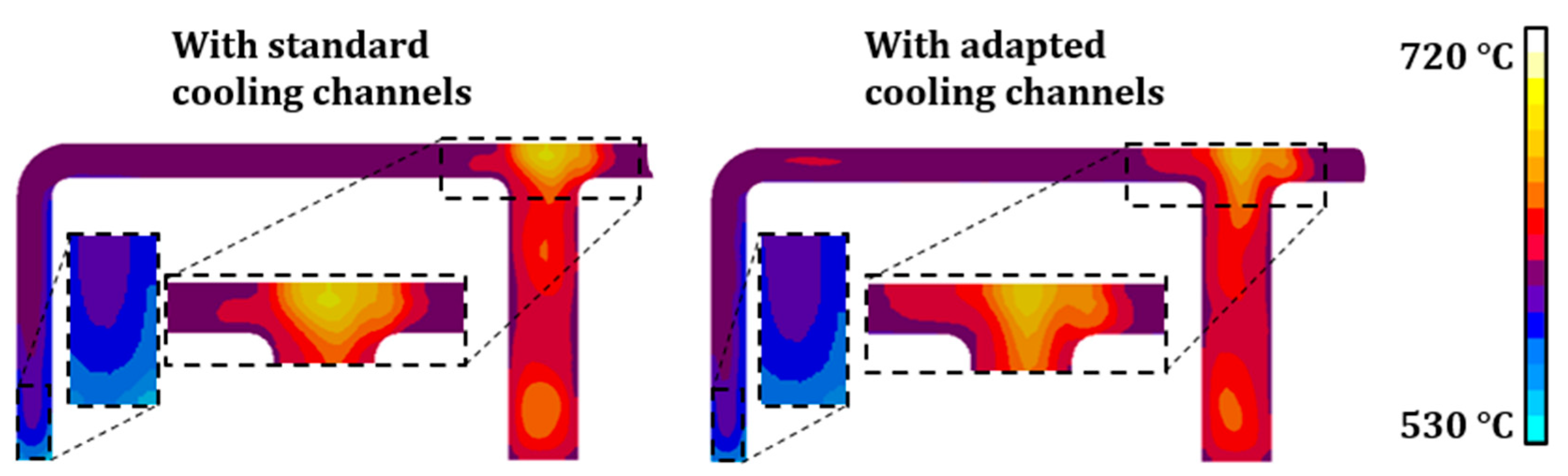
The accompanying simulations showed that cooling channels adapted to the heat distribution in the component can somewhat reduce the occurrence of thermal extremes in the component and mold. This is much less pronounced when considering the modules that can be used in reality, as could be seen in the first purely numerical considerations of idealized cooling channel layouts [
7]. The small extent of the expected differences makes a comparison of the measured in-situ values (here the temperature) with the calculated ones poorly possible. Important influential quantities such as the contact condition-dependent heat transfer between mold and component cannot be included at the current project status due to the non-quantifiable contact conditions. The simulation of the component distortion led to results that deviated strongly from reality, which is due to the cooling of the component in the mold down to ambient temperature before demolding, whereas the simulation refers to a practical manufacturing process where demolding temperatures are usually not below 300 °C [
23].
The evaluation of the recorded in-situ measurements showed that both the temperature and distance measurements worked as expected, but the latter and some of the former showed no correlation with the investigated variation of the cooling channel design. Furthermore, the load cell provided no useful results for the shrinkage force at all. The inconclusive metallographic investigations fit with the current knowledge that for typical solidifications in permanent mold casting of thin-walled components, as given here by the wall thickness and the steel mold, no large local changes of SDAS and grain size are observed. This results from the fact that the achievable differences are very small in the overall context (the thermal conductivity of aluminum is high, so very rapid heat equalization occurs). Nevertheless, a temporal variance in local microstructure formation may be present, causing differences in the observed component deformation.
The meaningful measured values are the temperatures in the core module and at the measuring points exactly opposite to them in the mold. The fact that the temperature values in the core for the layout with adapted cooling channels are higher than those in the conventional core is consistent with the fact that the measuring points are at a place of the component with little mass (and thereby little heat capacity). Therefore, the cooling channels are further apart, in order to cause a slower solidification in the adapted layout compared to the conventional one. The fact is that for the core module with adapted cooling channels the temperatures measured in the mold are higher fits as well. This is because the smaller quantity of heat dissipated in the core causes greater heating of the opposite mold module. The fact that the temperatures in the adapted core module decrease more slowly after casting can also be explained by the more distant cooling channels in this area.
The fact that the mean distortions determined for the variation with adapted cooling channels are higher for both geometries than with equidistant ones refutes the hypothesis, valid in plastic injection molding, that a homogeneously solidifying casting results in less distortion in metal casting. This result, in combination with the fact of numerically poorly mappable distortion for room temperature demolding, suggests that the major portion of the distortion is formed during in-mold hindered solid shrinkage of the casting and not at the point of solidification, which is also indicated in literature [
24].
The distortion considered here is caused by the shrinkage of the casting, which is hindered by the steel core, where the cores corners serving as abutments over which the legs of the “U” are pulled outward when the back of the “U” connecting them shrinks more than the core material. This can be explained by the thermal expansion coefficients of A356 for 2.15 × 10
−5 K
−1 at ambient temperature and 4 × 10
−5 K
−1 at 550 °C [
11], compared to that of the core module material (X38CrMoV5-1) with 1 × 10
−5 K
−1, which averaged about the associated temperature range.
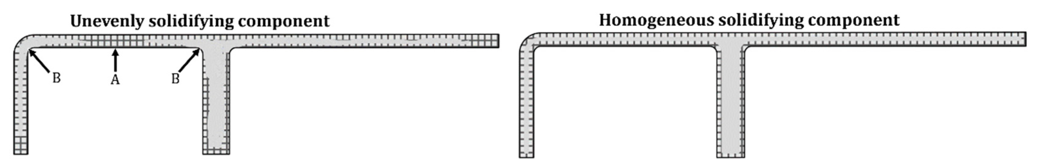
The fact that the mean distortion increases generally for the adapted cooling channels, and a more homogeneous solidification, can be interpreted appropriately in a way that a mechanically coherent dendrite structure is already present at a higher temperature. During cooling, since it has a mechanically loadable structure over a larger temperature interval, this develops more stresses—and thus distortion—when the mold constraint is removed, compared to the inhomogeneously solidifying component with more areas that are already solidified and at the same time still has liquid portions. This also fits with the larger dispersion of distortion within the series with conventional cooling channel layout. Here, the different local areas of the component start to develop mechanically loadable cohesion at different times. The standard deviation of the mean distortions for both component geometries in the variation with adapted cooling channels is significantly lower than in the variation with equidistant cooling channels. To illustrate this,
Figure 14 schematically shows the semi-solidified component, once unevenly solidifying on the left and homogeneously solidifying on the right. On the left, almost completely solidified areas (A) occur simultaneously with areas that have not yet solidified (B), and no mechanical load can yet be absorbed and distributed. On the right, however, a coherent structure capable of bearing mechanical loads has already been formed. This shows that there is a usable correlation between more homogeneous solidification and component distortion in metal casting to minimize distortion.
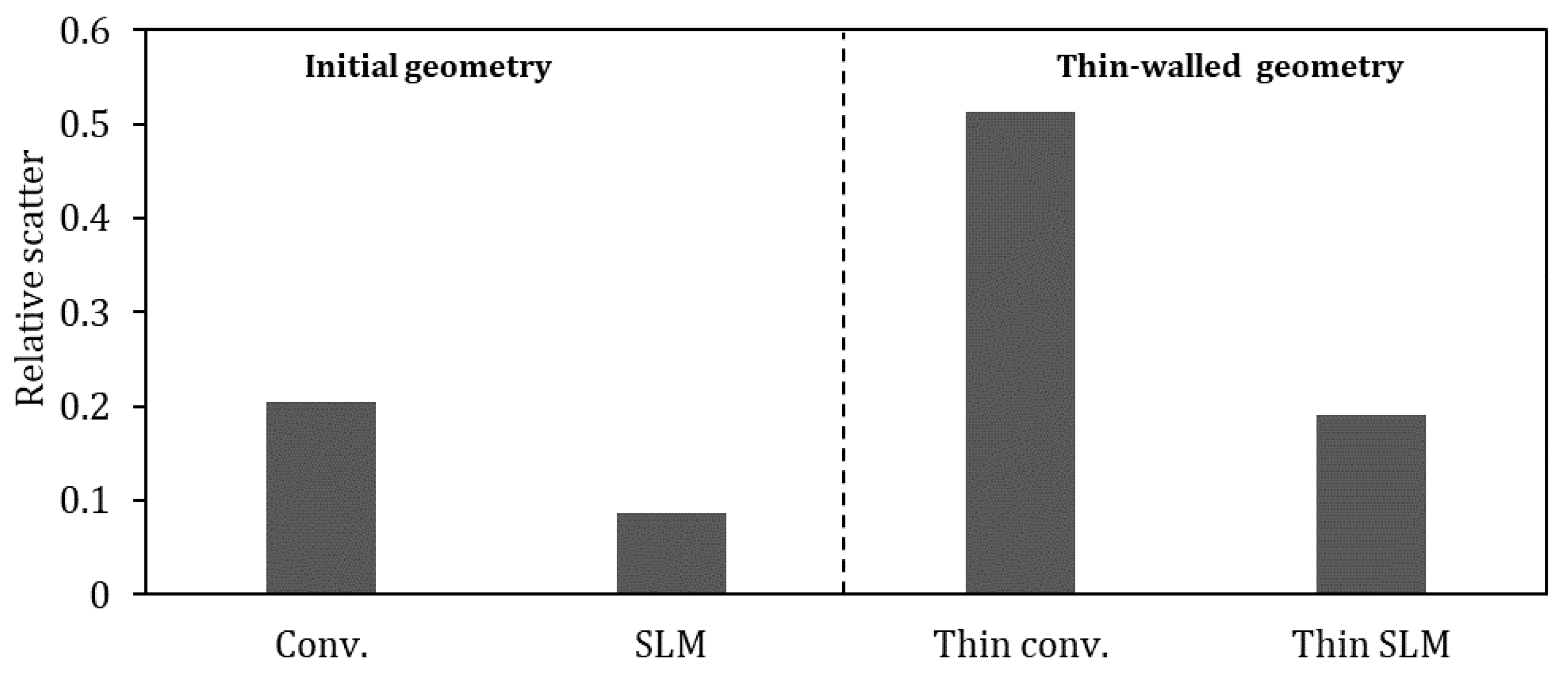
Since the resulting mean distortions differ significantly in amount, it seems obvious to normalize their standard deviations with the mean distortion of the corresponding component series. In this way, a dimensionless value is obtained for this relative scatter as an evaluation criterion. For the experiment series considered here, this is shown in
Figure 15. It can be seen that this value is lowest for the standard geometry and the variation with the SLM manufactured core module with the adapted cooling channels. This appears logical, since this was the design case for the layout of the adapted cooling channels. The value of 0.09 means that the standard deviation of the distortion of these series of components is a little less than one tenth of the mean distortion of all allocated specimens.
Author Contributions
Conceptualization, N.W. and T.H.; methodology, N.W. and T.H.; software, N.W.; validation, N.W., T.H. and U.V.; formal analysis, U.V.; investigation, N.W.; resources, N.W. and T.H.; data curation, N.W.; writing—original draft preparation, N.W.; writing—review and editing, U.V., A.B.-P. and C.H.; visualization, N.W.; supervision, U.V., A.B.-P. and C.H.; project administration, U.V., A.B.-P. and C.H.; funding acquisition, U.V., A.B.-P. and C.H. All authors have read and agreed to the published version of the manuscript.
Funding
This research was funded by the Deutsche Forschungsgemeinschaft e.V. (DFG, German Research Foundation).
Acknowledgments
The presented investigations were carried out at RWTH Aachen University within the framework of the Collaborative Research Centre SFB1120-236616214 “Bauteilpräzision durch Beherrschung von Schmelze und Erstarrung in Produktionsprozessen” and funded by the Deutsche Forschungsgemeinschaft e.V. (DFG, German Research Foundation). The sponsorship and support are gratefully acknowledged.
Conflicts of Interest
The authors declare no conflict of interest. The funders had no role in the design of the study; in the collection, analyses, or interpretation of data; in the writing of the manuscript, or in the decision to publish the results.
References
- Wolff, N.; Pustal, B.; Vossel, T.; Laschet, G.; Bührig-Polaczek, A. Development of an A356 Die Casting Setup for Determining the Heat Transfer Coefficient Depending on Cooling Conditions, Gap Size, and Contact Pressure. Mater. Sci. Eng. Technol. 2017, 48, 1235–1240. [Google Scholar] [CrossRef]
- Wolff, N.; Ahamadein, M.; Pustal, B.; Bührig-Polaczek, A. Identification of relevant Parameters for a gap and pressure dependent heat transfer model for different cooling conditions in gravity die casting. In Proceedings of the Liquid Metal Processing & Casting Conference, Birmingham, UK, 8–11 September 2019; pp. 319–325. [Google Scholar]
- Wolff, N.; Zimmermann, G.; Vroomen, U.; Bührig-Polaczek, A. A Statistical Evaluation of the Influence of Different Material and Process Parameters on the Heat Transfer Coefficient in Gravity Die Casting. Metals 2020, 10, 1367. [Google Scholar] [CrossRef]
- Laschet, G.; Vossel, T.; Wolff, N.; Apel, M.; Bührig-Polaczek, A. Multiscale solidification simulation of an axisymmetrical A356 component in die casting. In Proceedings of the 6th Decennial Conference on Solidification Processing—SP17, Old Windsor, UK, 25–28 July 2017. [Google Scholar]
- Vossel, T.; Pustal, B.; Bührig-Polaczek, A. Modellierung der Erstarrungskinetik kolumnarer und äquiaxialer Kornstrukturen zur gefügebasierten Interpolation der Werkstoffeigenschaften im Hinblick auf die Verzugsvorhersage. Gießerei Spec. 2017, 2, 130–134. [Google Scholar]
- Hopmann, C.; Nikoleizig, P.; Dornebusch, H.; Schneppe, T. Minimization of Warpage for Injection Molded Parts by Inverse Thermal Mold Design. Int. Polym. Process. 2018, 33, 110–116. [Google Scholar] [CrossRef]
- Hopmann, C.; Schneppe, T.; Theunissen, M.; Bührig-Polaczek, A.; Wolff, N. Investigation on the transferability of algorithms for the numerical optimization of cooling channel design in injection molding on metal gravity die casting. Mater. Sci. Eng. Technol. 2017, 48, 1220–1225. [Google Scholar] [CrossRef]
- Motoyama, Y.; Takahashi, H.; Inoue, Y.; Shinji, K.; Yoshida, M. Development of a device for dynamical measurement of the load on casting and the contraction of the casting in a sand mold during cooling. J. Mater. Process. Technol. 2012, 212, 1399–1405. [Google Scholar] [CrossRef]
- Motoyama, Y.; Takahashi, H.; Inoue, Y.; Shinji, K.; Yoshida, M. Dynamic measurements of the load on castings and the contraction of castings during cooling in sand molds. J. Mater. Process. Technol. 2013, 213, 238–244. [Google Scholar] [CrossRef]
- Eskin, D.G.; Suyitno; Mooney, J.F.; Katgerman, L. Contraction of Aluminum Alloys during and after Solidification. Met. Mater. Trans. A 2004, 35, 1325–1335. [Google Scholar] [CrossRef]
- Macht, J.P.; Maijer, D.M.; Phillion, A.B. A Combined Numerical–Experimental Approach to Quantify the Thermal Contraction of A356 During Solidification. Met. Mater. Trans. A 2017, 48, 3370–3376. [Google Scholar] [CrossRef] [Green Version]
- Galles, D.; Monroe, C.; Beckermann, C. Measurement and Prediction of Stresses during Casting of a Steel Bar. In Proceedings of the 65th SFSA Technical and Operating Conference Proceedings, Chicago, IL, USA, 7–10 December 2011. Paper No. 5.5. [Google Scholar]
- Galles, D.; Beckermann, C. Measurement and Simulation of Distortion of a Steel Bracket Casting. In Proceedings of the 66th SFSA Technical and Operating Conference Proceedings, Chicago, IL, USA, 12–15 December 2012. Paper No. 5.2. [Google Scholar]
- Kang, J.-W.; Long, H.-M.; Wang, T.-J.; Huwang, T.-Y.; Liu, B.-C. Evaluation of distortion of castings. Int. J. Cast Met. Res. 2011, 24, 228–232. [Google Scholar] [CrossRef]
- Hofer, P.; Kaschnitz, E.; Schumacher, P. Simulation of distortion and residual stress in high pressure die casting—Modelling and experiments. Mater. Sci. Eng. 2012, 33, 012055. [Google Scholar] [CrossRef]
- Hofer, P.; Kaschnitz, E.; Schumacher, P. Distortion and Residual Stress in High-Pressure Die Castings: Simulation and Measurements. JOM 2014, 66, 1638–1646. [Google Scholar] [CrossRef]
- Garza-Delgado, A. Study of Casting Distortion and Residual Stresses in Die Casting. Ph.D. Thesis, Ohio State University, Columbus, OH, USA, 2007. Available online: https://etd.ohiolink.edu/apexprod/rws_etd/send_file/send?accession=osu1196175848&disposition=inline (accessed on 15 October 2021).
- Armillotta, A.; Baraggi, R.; Fasoli, S. SLM tooling for die casting with conformal cooling channels. Int. J. Adv. Manufact. Technol. 2014, 71, 573–583. [Google Scholar] [CrossRef] [Green Version]
- Kochan, D.; Seifert, E.; Miksche, R. Werkzeugoptimierung für thermische Abformverfahren. Z. Für Fabrikbetrieb 2012, 107, 302–306. [Google Scholar] [CrossRef]
- Seidel, G. Heizung und Kuehlung von Druckgiessformen. Anordnung und Auslegung der Umlaufkanaele. Giesserei 1978, 65, 308–313. [Google Scholar]
- Gorbach, P. Handbuch der Temperierung Mittels Flüssiger Medien; Regoplas: St. Gallen, Switzerland, 2006; pp. 118–124. [Google Scholar]
- Schmidt, F. Einsatz Variothermer Temperiersysteme im Aluminiumdruckguss. Ph.D. Thesis, RWTH Aachen University, Aachen, Germany, 2019. [Google Scholar] [CrossRef]
- Brunhuber, E. Leichtmetall- und Schwermetallkokillenguss; Fachverlag Schiele & Schön GmbH: Berlin, Germany, 1966; pp. 182–186. [Google Scholar]
- Campell, J. Castings, 2nd ed.; Butterworth-Heinemann: London, UK, 2003. [Google Scholar]
Figure 1.
The input parameters, measured variables, and the target variables are shown together.
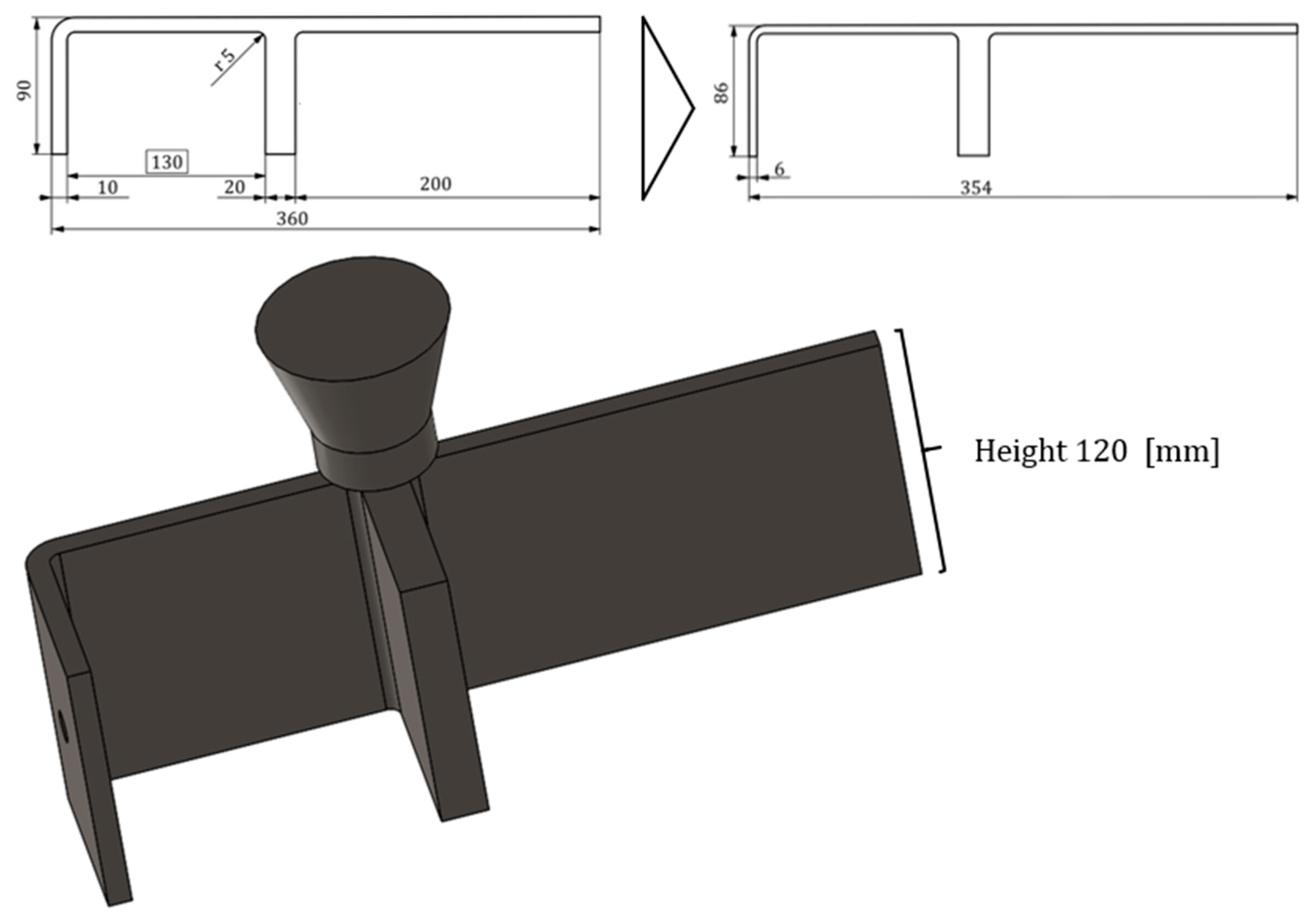
Figure 2.
On the top left, the geometry parameters for the test specimen with initial wall thickness and on the top right with its thin-walled configuration. On the bottom a CAD-model of the complete cast part with inlet-feeder.
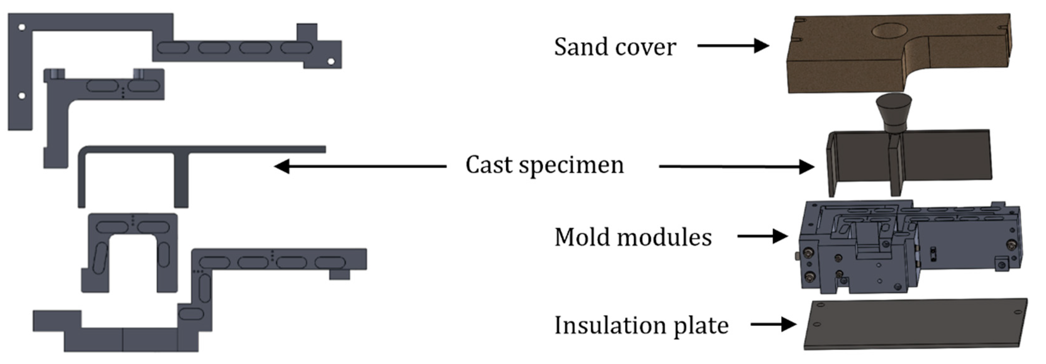
Figure 3.
On the left, the modular mold design can be seen, which allows changes to geometry, mold material, or other by exchanging individual modules. The right side shows the cast part, the assembled mold modules, and the calcium silicate bottom plate serving as insulator and the sand cover with integrated inlet-feeder.
Figure 4.
The four independent equidistant cooling circuits are shown in a plan view on the left and together with the test specimen in isometric view on the right.
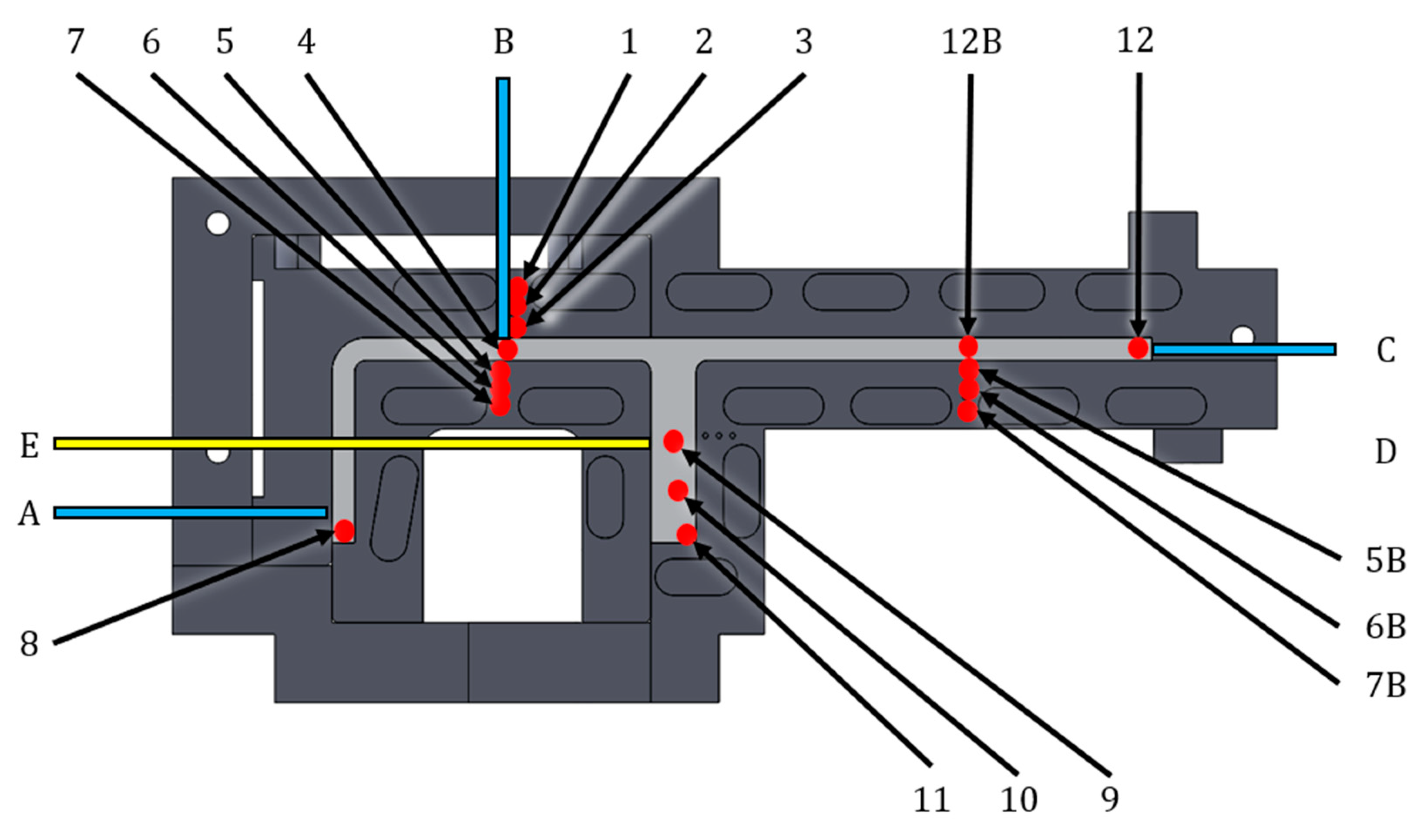
Figure 5.
Temperature measuring points (red) and the measuring points of the displacement transducer pairs (blue lines), as well as the point of application for the measurement of the shrinking force (yellow).
Figure 6.
Complete test setup prepared for the first test. The temperature measuring points (red), the displacement transducers (blue), and the load cell (yellow) are clearly visible.
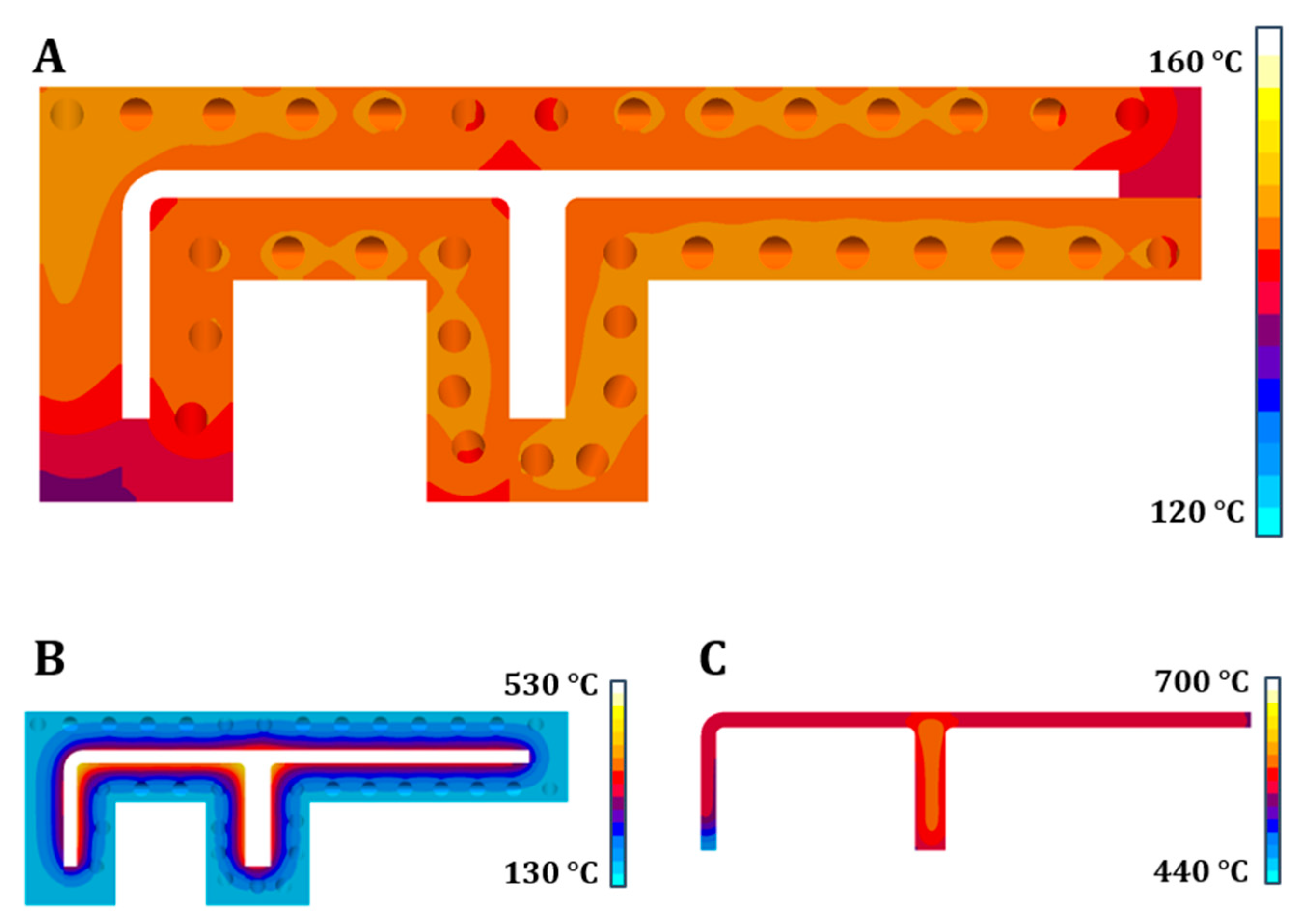
Figure 7.
On top (A) the heat distribution in the mold after 45 min of temperature control set to 150 °C. The calculated heat distribution in the middle plane when 50% off the material has solidified after 13 s are shown for the mold at the bottom left (B) and for the casting at the bottom right (C).
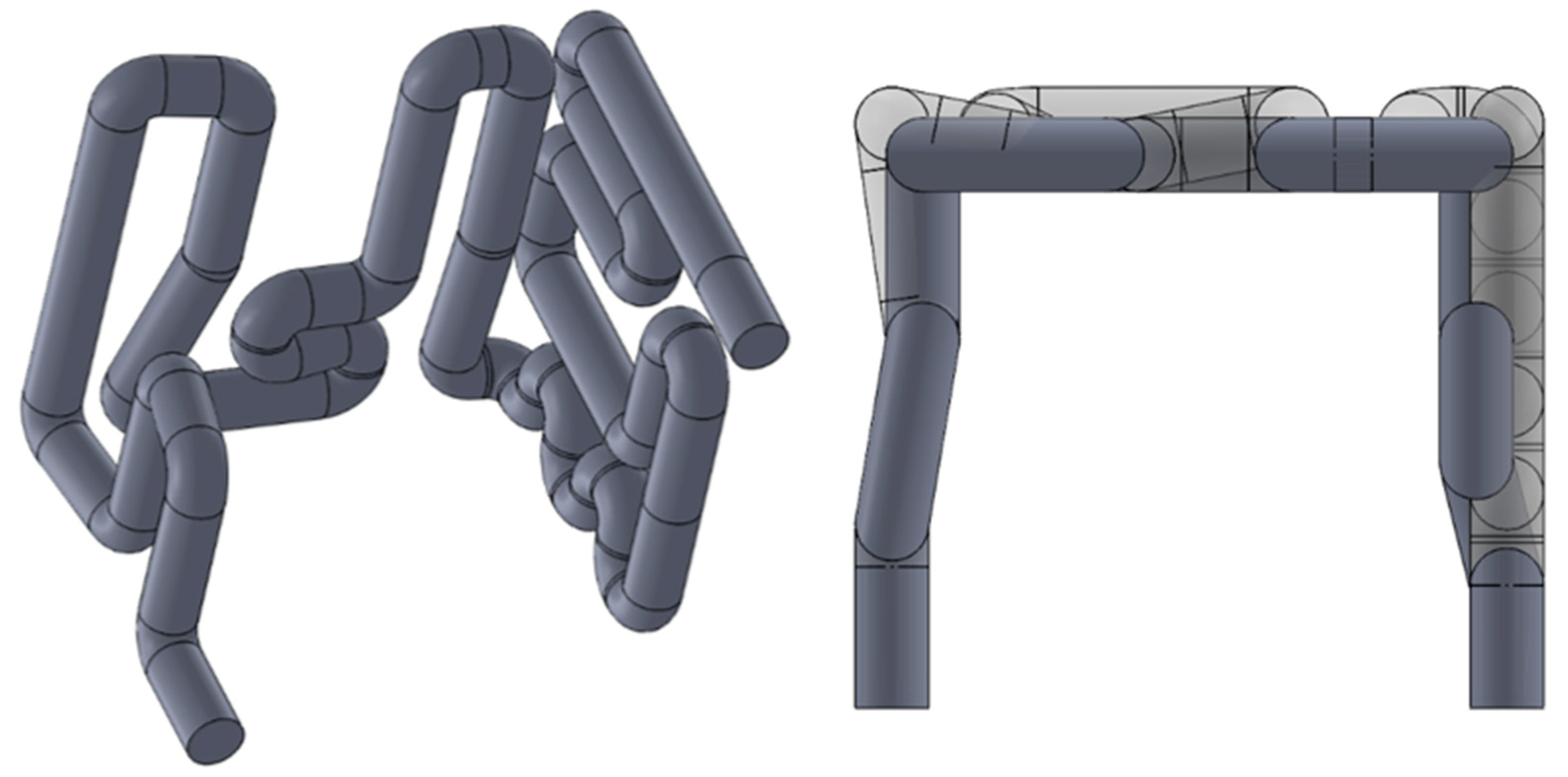
Figure 8.
The design of the cooling circuit in the SLM-manufactured core module on the left and on the right a top view where it can be seen that this circuit (here transparent) reaches further towards the corners of the core module than the conventional one (here solid).
Figure 9.
Temperatures at the end of pouring in the mid-plane of the cast part (U-section).
Figure 10.
The temperature distribution in the middle plane of the core module after 54 s of solidification when 80% of the material has solidified.
Figure 11.
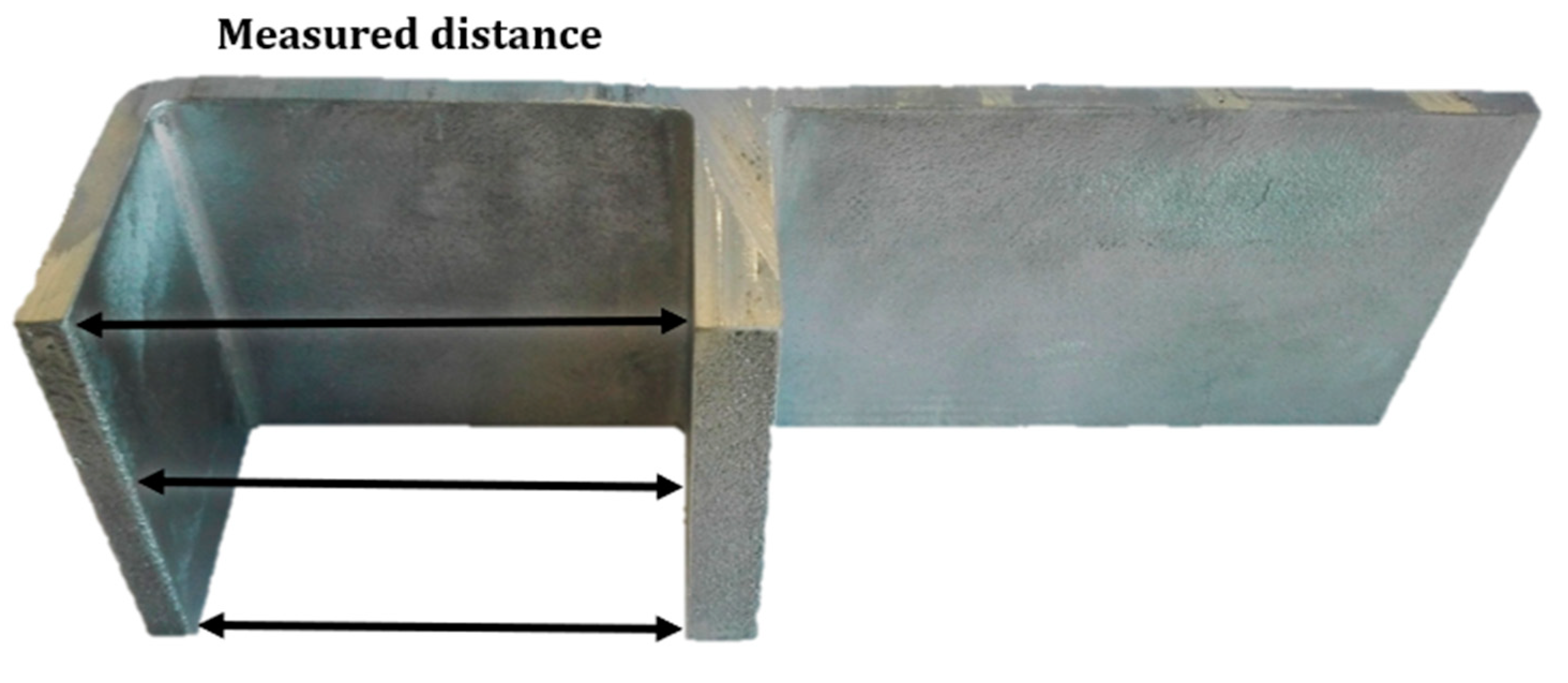
A Cast specimen with the initial geometry. On the left the measuring points for the component distortion are shown.
Figure 12.
In-situ measured temperatures of casting experiments in the initial geometry and temperature control set to 30 °C.
Figure 13.
Mean distortion and standard deviation for the different series.
Figure 14.
Schematic representation of the semi-solidified component, once unevenly solidifying (left) and once homogeneously solidifying (right).
Figure 15.
Relative scatter for the different test series.
| Publisher’s Note: MDPI stays neutral with regard to jurisdictional claims in published maps and institutional affiliations. |
© 2021 by the authors. Licensee MDPI, Basel, Switzerland. This article is an open access article distributed under the terms and conditions of the Creative Commons Attribution (CC BY) license (https://creativecommons.org/licenses/by/4.0/).


 ,
, 