Article

Spatter Formation and Splashing Induced Defects in Laser-Based Powder Bed Fusion of AlSi10Mg Alloy: A Novel Hydrodynamics Modelling with Empirical Testing

by
Asif Ur Rehman
1,2,3,*,†,
Muhammad Arif Mahmood
4,*,†,
Peyman Ansari
2,3,
Fatih Pitir
1,
Metin Uymaz Salamci
2,3,5,
Andrei C. Popescu
4 and
Ion N. Mihailescu
4
1
ERMAKSAN, Bursa 16065, Turkey
2
Department of Mechanical Engineering, Gazi University, Ankara 06570, Turkey
3
Additive Manufacturing Technologies Research and Application Center-EKTAM, Gazi University, Ankara 06560, Turkey
4
National Institute for Laser, Plasma and Radiation Physics (INFLPR), Ilfov, 077125 Magurele, Romania
5
Manufacturing Technologies Center of Excellence-URTEMM A.S., Ankara 06980, Turkey
*
Authors to whom correspondence should be addressed.
Both authors have participated equally.
Metals 2021, 11(12), 2023; https://doi.org/10.3390/met11122023
Submission received: 9 October 2021 / Revised: 7 December 2021 / Accepted: 10 December 2021 / Published: 14 December 2021
(This article belongs to the Special Issue Metal Additive Manufacturing Processes and Applications)

Abstract

:
Powder spattering and splashing in the melt pool are common phenomena during Laser-based Powder Bed Fusion (LPBF) of metallic materials having high fluidity. For this purpose, analytical and computational fluid dynamics (CFD) models have been deduced for the LPBF of AlSi10Mg alloy. The single printed layer’s dimensions were estimated using primary operating conditions for the analytical model. In CFD modelling, the volume of fluid and discrete element modelling techniques were applied to illustrate the splashing and spatter phenomena, providing a novel hydrodynamics CFD model for LPBF of AlSi10Mg alloy. The computational results were compared with the experimental analyses. A trial-and-error method was used to propose an optimized set of parameters for the LPBF of AlSi10Mg alloy. Laser scanning speed, laser spot diameter and laser power were changed. On the other hand, the powder layer thickness and hatch distance were kept constant. Following on, 20 samples were fabricated using the LPBF process. The printed samples’ microstructures were used to select optimized parameters for achieving defect-free parts. It was found that the recoil pressure, vaporization, high-speed vapor cloud, Marangoni flow, hydraulic pressure and buoyancy are all controlled by the laser-material interaction time. As the laser-AlSi10Mg material interaction period progresses, the forces presented above become dominant. Splashing occurs due to a combination of increased recoil pressure, laser-material interaction time, higher material’s fluidity, vaporization, dominancy of Marangoni flow, high-speed vapor cloud, hydraulic pressure, buoyancy, and transformation of keyhole from J-shape to reverse triangle-shape that is a tongue-like protrusion in the keyhole. In the LPBF of AlSi10Mg alloy, only the conduction mode melt flow has been determined. For multi-layers printing of AlSi10Mg alloy, the optimum operating conditions are laser power = 140 W, laser spot diameter = 180 µm, laser scanning speed = 0.6 m/s, powder layer thickness = 50 µm and hatch distance = 112 µm. These conditions have been identified using sample microstructures.

1. Introduction

Additive manufacturing (AM) provides customized design, reduced processing time and the ability to create complicated shapes. It has garnered a lot of attention from sophisticated technological applications [1], aerospace [2], biomedical [3,4,5] and construction [6,7]. Amongst the most sophisticated and efficient AM processes is laser powder bed fusion (LPBF) [8,9]. In this process, a laser beam is used to fuse the particles [10]. Aluminum (Al) alloys are unique amongst metallic powders employed in LPBF due to inherent lightness [11]. The high heat conduction, as well as oxidation of Al alloys, are challenging issues during LPBF. Heating dynamics and cracking processes are strongly influenced by conduction [12], due to the numerous physical processes involved in LPBF, such as laser-matter interactions and melting-solidification hysteresis. The melt pool largely determines surface morphology and physical attributes due to laser beam contact with metallic powders. One can identify that the LPBF multi-physics is a combined effect of heat transfer and temperature at the interface [13,14,15].
On the other hand, several operating conditions, including beam power, scan rate and beam spot radius, influence melt pool formation characteristics [16]. Furthermore, keeping the melt pool’s heat consistent and preventing deviations in thermal gradient throughout the manufacturing process can establish a consistent and predictable morphology in the finished part. Experiments in research labs are now commonly used to obtain optimum process parameters. Shi et al. [17] used the single track technique to extract and optimize the process parameters for LPBF of Ti47Al2Cr2Nb metallic powders. To simulate a single layer printing of AlSi10Mg metallic powders, Liu et al. [18] formulated a three-dimensional (3D) analytical model using a finite element (FE) analysis approach.
Researchers have developed an exact transient simulation for predicting the microstructure and temperature variations during the LPBF process. Liu et al. [19] developed a thermodynamic 3D numerical simulation model to show the effectiveness of multi-layer scanning in the case of LPBF of AlSi10Mg alloy. Using computational thermal analysis, Han et al. [20] investigated the microstructural characteristics of LPBF-ed Al-Al2O3 nanocomposite. To explore the impact of the track width and height on developing the temperature and melt pool qualities of AlSi10Mg alloy LPBF, Liu et al. [21] developed and used a heat flux model to estimate the influence of melt pool attributes and temperature inside the printed layers. Li and Gu [22] developed a 3D thermodynamic numerical model to study the impact of laser power and scan speed on the thermal attributes of LPBF-ed AlSi10Mg. Du et al. [23] deduced a thermal model to forecast the thermal distribution of the AlSi10Mg melt pool during the LPBF process. Specifically, they observed the effects of beam power with scan rate on thermodynamic properties in the LPBF technique. To verify the model, investigators recorded thermal distribution in the case of a single scan. Ur Rehman et al. developed the simulation models for laser melting deposition using the volume of fluid and discrete element modeling techniques for AISI 304 stainless steel [24] and Ti6Al4V [25] materials. In the simulations, a method was deduced to track the flow behavior, flow pattern and driving forces of liquid flow involved in the LPBD of AISI 304 stainless steel and Ti6Al4V materials. The models were able to produce results with a mean deviation of 1–3% compared to experimental results. Oane et al. [26] developed computational model for laser additive manufacturing of metals and organic materials. These models were able to present results accurately with a deviation of up to 15%.
In LPBF, laser-metallic powder interaction optimization is essential in determining the operating conditions. For this purpose, Matthews et al. [27] studied the denudation of metallic powders identified near the laser beam scanning path due to laser operating conditions and gas pressure. It was found that the metallic powder depletion in the zone immediately surrounding the solidified track is due to a competition between outward metal vapor flux directed away from the laser spot and entrainment of powder particles in a shear flow of gas driven by a metal vapor jet at the melt track. Furthermore, the denuded zone width rises with the decrease in ambient gas. Ly et al. [28] presented the detailed experiments and finite element modeling of metal micro-droplet motion in metal AM. High-speed imaging of melt pool dynamics indicated that the major mechanism leading to micro-droplet ejection in an LPBF is not laser produced recoil pressure, as is widely assumed and found in laser welding processes, but rather vapor driven entrainment of micro-particles by an ambient gas flow. In metal AM, spattering is a dominant problem. A thorough understanding of the laser-spattering phenomenon, particularly the highly fast spatters, has yet to be obtained due to the limitations of in situ diagnostic procedures, which normally use visible light or laboratory x-ray sources. Zhao et al. [29] investigated the spattering phenomenon in Ti6Al4V with micrometer spatial resolution and sub-nanosecond temporal resolution using MHz single-pulse synchrotron-x-ray imaging. They identified that the bulk explosion of a tongue-like protrusion growing on the front keyhole wall causes the molten metal ligamentation at the keyhole rims. In References [30,31], Ni-based super-alloy IN713-LC, considered as non-weldable, were printed using a proper selection of laser power and scanning speed. It was found that with an appropriate selection of the LPBF processing conditions, the mechanical properties of IN713LC are superior to those achieved via casting. An integrated simulation framework consisting of a 3D finite element model and a cellular automaton model was developed to predict the epitaxial grain growth mode in the single-track and multi-track for Inconel 718 for the LPBF process [32,33]. Furthermore, a hybrid finite element (FE) and cellular automaton (CA) model was developed to explore crystallization behavior and alloying of Inconel 713LC during LPBF [34]. During LPBF processing of IN713LC, it was found that the micro segregation of Nb, Ti and C accrued at the grain boundaries. In addition, the micro segregation intensity depends on the solidification speed, which is determined by the laser heat input. In particular, a lower laser heat input increases the solidification speed and results in a more uniform solid phase, thereby reducing the risk of crack formation.
Nevertheless, the LPBF-FE cannot provide us with splashing since it does not include all the multi-physics involved in the calculations. Without various flow dynamics, the key drivers of the stream cannot be included in the simulation, which is a significant disadvantage for FE techniques. For example, Mukherjee et al. [35] proposed a 3D temporal heat flux and flow framework to evaluate the impact of different factors, such as energy density, melt pool form and shape on metallurgical integrity Ti6Al4V, IN718, stainless steel 316 and AlSi10Mg alloy. The model was validated with the experimental results involving several layers and multiple hatches. Pei et al. [36] investigated the melt pool dynamics under LPBF utilizing AlSi10Mg powders. Researchers formulated a 3D model and then used the discrete element technique for randomly distributed particles. They studied the laser beam scan rate, laser power and hatch distance. Courtois et al. [37] modelled the keyhole formation in the LPBF process using the beam multi-reflection ray tracing. They compared the model with the actual micrographs obtained via experimentation. Mahmood et al. [38] investigated the effect of process parameters on microstructure formation in the case of AISI 304 stainless steel. A multi-physics model was developed by including the primary operating conditions, including laser beam power, scan speed and beam spot radius.
Various studies have been carried out for the LPBF process modelling of AlSi10Mg alloy. However, to the best of the authors’ knowledge, no study has reported and discussed the spatter and splashing formation involved in the AlSi10Mg alloy printing via the volume of fluid (VOF) and discrete element modelling (DEM) techniques. For this purpose, this article discusses the single-layer deposition of AlSi10Mg alloy by utilizing analytical and computational fluid dynamics (CFD) models. The single layer’s dimensions have been calculated using the primary operating conditions by applying a simplified deduced mathematical model. The VOF and DEM techniques have been integrated into the CFD modeling to identify the splashing and spatter formation in the LPBF of AlSi10Mg alloy, thus describing the AlSi10Mg hydrodynamics in a powder layer under the action of a laser. The simulation results have been compared with the experimental ones. In addition, the effect of operating conditions on the surface morphology has been identified to determine the optimum operating conditions. In simulations, a method to monitor the flow behavior across the full melt pool has been devised. The overall flow behavior of the melt pool was also discovered. The driving forces behind the fluid movement, splashing and spatter formation have been studied.

2. Modelling

This section has been divided into two parts: (a) analytical modelling and (b) computational fluid dynamics (CFD) modelling.

2.1. Analytical Modelling

Following assumptions were taken into account while estimating the geometry of the deposited layer:
  • The speed of the laser beam is constant, and the focused laser spot is circular. The deposited layer’s geometry is taken as elliptical. It is because the laser energy distribution in the beam’s laser cross-section has been considered Gaussian. This type of energy distribution yields a convex shape deposited layer, along the cross-section that can be correlated with an “elliptical” profile [39].
  • The surface tension can be determined via the microscopic structure of the liquid near the surface. At the liquid–vapor interface, the density changes severely from a high value in the liquid state to a very low in the gas phase. Surface atoms experience an “attraction” toward the liquid phase, which originates from the surface tension. This study conducted the measurements via post-processing techniques because in situ layer deposition was not monitored experimentally. Thus, the surface tension of the melt flow was neglected. In addition, the thickness of the powder layer is known to be an input in the LPBF process.
The laser beam energy dissipation by the powder granules is constant, and the powder particles’ mean size is considered [40,41]. While forming a powder bed, the overlapping by the powder particles is ignored.
In laser powder bed fusion (LPBF), the heating of the powder layer can be described using the Beer–Lambert law as
m o C p * T = I o e α h
Here, m o is the mass printed on the substrate as a result of melting, C p * is the modified powder particles specific heat, T is the temperature difference, I o is the incident laser intensity, α the material’s laser absorptivity coefficient, and h is the height (thickness) of the deposited layer along the universal z-axis. In equations, m and C p * can be expressed as
m = π l r c 2 ρ p t p l
C p * = L f T ( y , t ) T o + C p .
Here, ρ p , t p l and lrc are the powder particles’ density, layer thickness and radius of the circular base plate used in LPBF process. Furthermore, Lf is the fusion enthalpy of powder particles, To is the room temperature, T(y, t) is the one-dimensional transient temperature for laser–powder particles interaction, and C p is the powder material specific heat calculated as
C p = ( 1 ) C b ,
where C b is the specific heat of the bulk material, and is the voids ratio, calculated as
= 1 π r p 2 S .
In the current study, the powder particle heating, melting and vaporization, responsible for inducing recoil pressure, have been taken into consideration with the inclusion of material enthalpy of fusion and specific heat capacity. Here, the enthalpy of fusion is defined as “the change in the material enthalpy resulting from providing energy, typically heat, to a specific quantity of the substance to change its state from a solid to a liquid, at constant pressure” [42]. Furthermore, specific heat capacity is defined as the “heat capacity of a sample of the substance divided by the mass of the sample” [43]. In this study, both of the quantities mentioned above have been taken as a function of transient temperature distribution (Equation (3)), which indirectly considers the material overheat based on the operating conditions. Equation (4) correlates with Equation (3) that recalculates the specific heat capacity based on the voids ratio that is an inherent characteristic of the LPBF process. In the present analytical study, an average radius of powder particles has been considered to calculate the void ratio. However, while considering the laser absorption or shading, it is extremely essential to consider the cross-section normal to the luminous flux that becomes ( π r p s ) [44]. It is the reason why only the average powder particle was taken into consideration. In Equation (5), rp is the mean radius of the powder particles, and S is the surface area of the powder bed. For a Gaussian laser beam having laser power P and radius rp, the intensity can be shown as [45]:
I o = 2 P π r p 2 .
Now, the mass-printed ( m o ) on the substrate, as a result of melting, depends on the laser scanning speed (Vs), laser–material exposure time (to) and layer’s length (L) in the following way:
m o = m V s t o L .
In laser–material interaction, the amount of material melted, resulting in solidification, is dependent on energy transfer from laser to the material. Since the laser power has already been considered (Equation (6)), the laser scanning speed and laser–material interaction (process time) have been taken into account using Equation (7), applicable only if the length of the deposited layer is known. The thermal distribution difference ( T ) can be expressed as:
T = T ( y , t ) T o ,
After substituting the Equations (2)–(8) in Equation (1), rearranging and applying natural log, the following expression is achieved:
h = | 1 α l n ( π r p 2 ρ p V r c t p l l r c V s t o ( L f T ( y , t ) T o + C ) ( T ( y , t ) T o ) 2 P L ) | ,
The h value can be estimated if T(y, t) is known that can be expressed as [46]:
T ( y , t ) = T o + 3 2 ρ p C p π Q 12 α t + r p 2 e x p [ y 2 4 α t + y 2 r p 2 4 α t { 12 α t + r p 2 } ] e r f [ 12 α t y r p + r p 2 2 α t { 12 α t + r p 2 } ] + e x p [ y 2 4 α t + y 2 r p 2 4 α t { 12 α t + r p 2 } ] e r f [ 12 α t + y r p + r p 2 2 α t ( 12 α t + r p 2 ) ] .
In Equation (10), Q is the thermal energy per unit area, t is the total laser–powder interaction time, and erf is an error function that occurred when integrating a normalized distribution [47]. Assuming the shape of the deposited layer elliptical, the width (w) and depth (d) of a single layer can be calculated, based on h, using the following expression [48]:
w = 4 2 M p π h V s ρ p .
d = [ 2 ( P L V s ) ] [ 2 ρ p V r c t p l l r c   L C p * ] [ π 6 ρ s V s W 1 L C s * ] .
Here, L is the length of the deposited layer, 2 is the powder utilization efficiency, and C s * is the modified specific heat of substrate, defined as:
C s * = L f s T m s T o + C s .
It is worthy of mentioning that the LPBF does not utilize the entire powder spread on the substrate by the re-coater, resulting in powder utilization efficiency ( 2 ) that can be calculated after ignoring the dilution rate as
2 = w ( c ) e x p h ( c ) e x p π r p 2 .
Here, rp is the laser beam spot radius, and w(c)exp and h(c)exp are the experimentally printed layer’s width and height, respectively. As mentioned in Equation (1), m is the powder mass deposited on the substrate by the powder coater, while Equation (14) provides the fraction (%) of the powder mass used for LPBF printing, also known as powder utilization efficiency, compared to the whole powder layer deposited by the powder coater.

2.2. Numerical Modelling

Many powder particles fall and generate a powder bed at the beginning of the powder development and deposition process. For powder particles, an interactive method based on the nonlinear Hertz–Mindlin elastic equation [49] measures the actual elastic contact force between the particles. Mechanical energy dissipation is also taken into consideration when computing the damping factor [50,51,52]. Among these interacting particles, the perpendicular contact force and damping force naturally occur. The relative stiffness of the plane is uniformly perpendicular throughout the whole plane. In addition, the mass and Young’s modulus are interchangeable. No micro-slip method is employed in the tangential route to deal with the elastic contact force [49]. AlSi10Mg powder particles were deposited using the Flow Science, Discrete Element Modelling (DEM) module from Flow Science, USA. This module allows the user to simulate the powder layer based on the particle size distribution (PSD) and the corresponding packing density. Hence, the powder layer was developed using micro-particles with a diameter of just a few microns with a packing density equal to 63%. Particle size distribution acquired by SEM versus software is shown in Figure 1a,b, respectively. It is worthy to mention that SEM was used to determine the powder particles’ morphology. For simulation, the PSD was used as an input to compute the powder layer formation.
In LPBF, the powder layer is melted and solidified quickly, thus changing its thermo-physical characteristics. In the current CFD model, AlSi10Mg powder material’s thermophysical properties are taken as temperature-dependent. A CFD framework was developed and deployed using the FLOW-3D CFD module and specialized sub-processes.
The FLOW-3D 11.2v CFD software and additive manufacturing from Flow Science, USA, were used to develop and integrate a CFD framework. In this research, multiple variables and generalizations have been made: (a) the melting is assumed incompressible Newtonian throughout the melt stream, and (b) the change in mass owing to metal evaporation is taken into account. Continuity of mass, momentum and energy conservation are all solved by using the following equations:
· v = 0 .
v t + ( ν ) v = 1 ρ P + μ 2 v + g [ 1 α ( T T m ) ] g [ 1 α ( T T m ) ] .
h t + ( v · ) h = 1 ρ ( · k T ) .
where v defines the velocity profile, P identifies pressure, μ specifies viscosity, and g represents the gravity function, α specifies the coefficient of thermal expansion, ρ specifies density, h denotes specific enthalpy, and k is heat conductivity. A volume of fluid (VOF) model has been applied as shown in Equation (18) [53]:
V F t + ( ν V F ) = 0 .
The metal volume fraction ( V F ) is used to specify the fluid: cells are said to be completely fluid if V F = 1 , whereas if the cells that have no fluid inside them, V F = 0 . Melt pool dynamics usually vary due to thermo-physical characteristics, vapor suppression and penetration. Since the Rosenthal method is re-derived from the heat equation and eliminates evaporation, convection and the Marangoni effect [54,55], the equivalent term in Equation (19) shows the melt pool diameter extracted from the Rosenthal formula [56]. It explains the significance of thermo-physical features in melt pool heterogeneity during heat transfer [54] as
ω = 8 π e P η ρ C p V ( T m T 0 ) .
Here, the melt pool width is specified by ω , the beam power is specified by P, laser beam absorptivity is η, density is ρ , and C p is the heat capacity. Furthermore, V specifies the laser beam scanning speed, and the melting temperature is specified by T m and the pre-heating level is specified by T 0 . Thermal independence and thermophysical conductivity to measure the melt pool size are presumptions in determining the Rosenthal solution. The impact of recoil pressure and vapor suppression on melt pool size is also considered [52,57]. Equation (20) is used to determine the recoil pressure:
P S = A e x p { B ( 1 T V T ) } .
The secondary coefficient A is equal to β P 0 , β ∈ [0.54,0.56], and P 0 is the atmospheric pressure. The B = Δ H v / R T v , where Δ H v is an accumulated vaporization heat [57], R stands for gas constant, and T v is the saturation temperature [52,57]. Here, the laser energy density is distributed in accordance with a gaussian curve. The laser beam scanning speed is constant, and the energy density (q) of the beam is expressed as [57]:
q = 2 A p π R b 2 e x p [ 2 ( x ν t x 0 ) 2 + ( y y 0 ) 2 R b 2 ] ,
where A denotes the particle bed’s beam absorbance, p denotes the laser power, Rb denotes the laser beam spot radius, v denotes the scanning rate, and x 0 and y 0 represent the original position of the laser beam center [57]. The beam radius, R b , is set as 27.5 m. However, evaporation is critical when considering the hot surface of the melt pool due to convection and radiation. As a consequence, the governing equation [57] may be represented primarily on the melt pool surface as
T n = q h C ( T 1 T 0 1 ) σ 0 ε ( T 4 T 0 4 ) q e v a p .
Here, h c is the coefficient of convection heat transfer, T 0 is the room temperature, σ 0 is the Stefan–Boltzmann constant, and ε is an emissivity measurement. The temperature distribution owing to evaporation ( q e v a p ) [52] is represented as
q e v a p = ω 0 L v = e x p ( 2.52 + 6.121 18836 T 0.5 l o g T ) L v .
where ω 0 is the evaporation rate. To calculate the mass flow rate, the following equation has been applied:
m ˙ = ρ v d A .
Here, v is velocity, and ρ is density. Simulation values were supposed for height to reflect a close change with experimental results.

3. Materials and Methods

To validate the developed CFD and analytical models, the study of Pezzato et al. [58] has been chosen. The CFD layer after the LPBF simulation is non-uniform; therefore, the closest value to the study of Pezzato et al. [58] has been supposed for the layer height after the irradiation. In this study, LPBF printing of AlSi10Mg was carried out using the parameters provided in Table 1.
Following that, 20 samples were fabricated as bars having the dimensions: number of layers = 400, diameter = 10 mm and length = 80 mm. For microstructure analysis, the samples were cut in the dimensions of 2.5 (mm) × 10 (mm) × 50 (mm) at the Additive Manufacturing Technology Application and Research Center (EKTAM), Gazi University, Turkey. For LPBF printing, powder layer thickness and hatch distance were set as 50 µm and 112 µm, respectively. Samples were fabricated using gas atomized AlSi10Mg powders by Concept Laser. Table 2 shows the powder composition of AlSi10Mg, respectively.
According to ASTM B822, AlSi10Mg powder particles size distribution is given Table 3 [59].
All the specimens were printed using machine A. For this machine, the maximum laser power is 400 W operating in a continuous wave mode using ytterbium fiber laser (1070 nm wavelength). This machine provides a wide range of selection parameters via a user interface, including powder layer thickness, hatch distance and spot size variation. The specimen’s build chamber was controlled using a nitrogen atmosphere. A study was reported by Pauzon et al. [60] on the effect of argon and nitrogen atmospheres on the properties of LPBF parts. It was claimed that the parts developed in the nitrogen gas protective environment presented better mechanical properties, including yield and tensile strengths, than those manufactured in an argon protective environment. It is the reason why nitrogen gas was used in current research. Table 4 collects the operating conditions used to deposit AlSi10Mg samples. In this study, a trial-and-error method was used to choose an optimized set of parameters in the case of AlSi10Mg LPBF. For this purpose, the primary operating conditions such as laser scanning speed, laser spot diameter and laser power were varied, while, the powder layer thickness and hatch distance were kept fixed. Following on, all the samples’ microstructures were investigated using DMi8 Leica Microsystems optical microscope. An optimized set of operating conditions was defined to attain defect-free parts based on the captured microstructure.

4. Results and Discussions

In the case of AlSi10Mg single layer LPBF printing, Figure 2 shows a comparison among experiments [58], CFD simulation and analytical computations in the case of printed layer height along the z-axis after LPBF. The CFD simulation results were much closer to the experimental ones, except for a 2–4% mean absolute variation, compared to the analytical computations with 7–10% deviations. The primary reason for this deviation, for analytical simulations, is the negligence of surface tension, 35% powder utilization efficiency and inclusion of mean powder particle radius during LPBF printing. During the analytical modelling, only mean powder particle radius was taken into consideration due to that fact while considering the laser absorption or shading, it is essential to consider the cross-section normal to the luminous flux that gives π r p s . This necessity will be compromised if PSD is taken into consideration, analytically. Here, the powder utilization efficiency is defined as the ratio between the actual powder volume used in the printing process to the total powder supplied during the LPBF process [48]. A close correlation with the experimental results identifies that these models can be used for selection and optimizing parameters.
Figure 3a–d shows the splashing phenomenon identified during the LPBF printing of AlSi10Mg alloy. The presence of Si-content improves the fluidity, wear-resistance and age hardening of the AlSi10Mg alloy compared to Al-Mg alloy [61]. As shown in Figure 3a, no splashing was identified; however, the splashing becomes dominant when the laser–material interaction time increase, as presented in Figure 3b–d. It can be explained by the fact that the density of the material is in inverse correlation with temperature change. As the temperature increases due to higher laser–material interaction, the material’s specific heat and latent heat of fusion change, resulting in density declination, thus increasing the fluid volume. In addition, for melt flow, five key driving forces have been identified: (a) Marangoni flow, (b) vaporization, (c) high-speed vapor cloud, (d) hydraulic pressure and (e) buoyancy [62,63,64]. For a material with a negative thermal surface tension coefficient, “Marangoni convection” flows from an elevated to a low thermal regime. The inner compression caused by “vaporization” induced-recoil pressure is perpendicular to the evaporated surface. Friction at the gas–liquid periphery can produce shear force in a “high-speed vapor cloud.” The term “hydraulic pressure” refers to transferring energy using either hydrostatic or hydrodynamic pressure. The melted material is compelled to follow the density gradient due to the “buoyancy force.” In addition, four events are responsible for the splashing phenomenon in metal laser AM [29,65]:
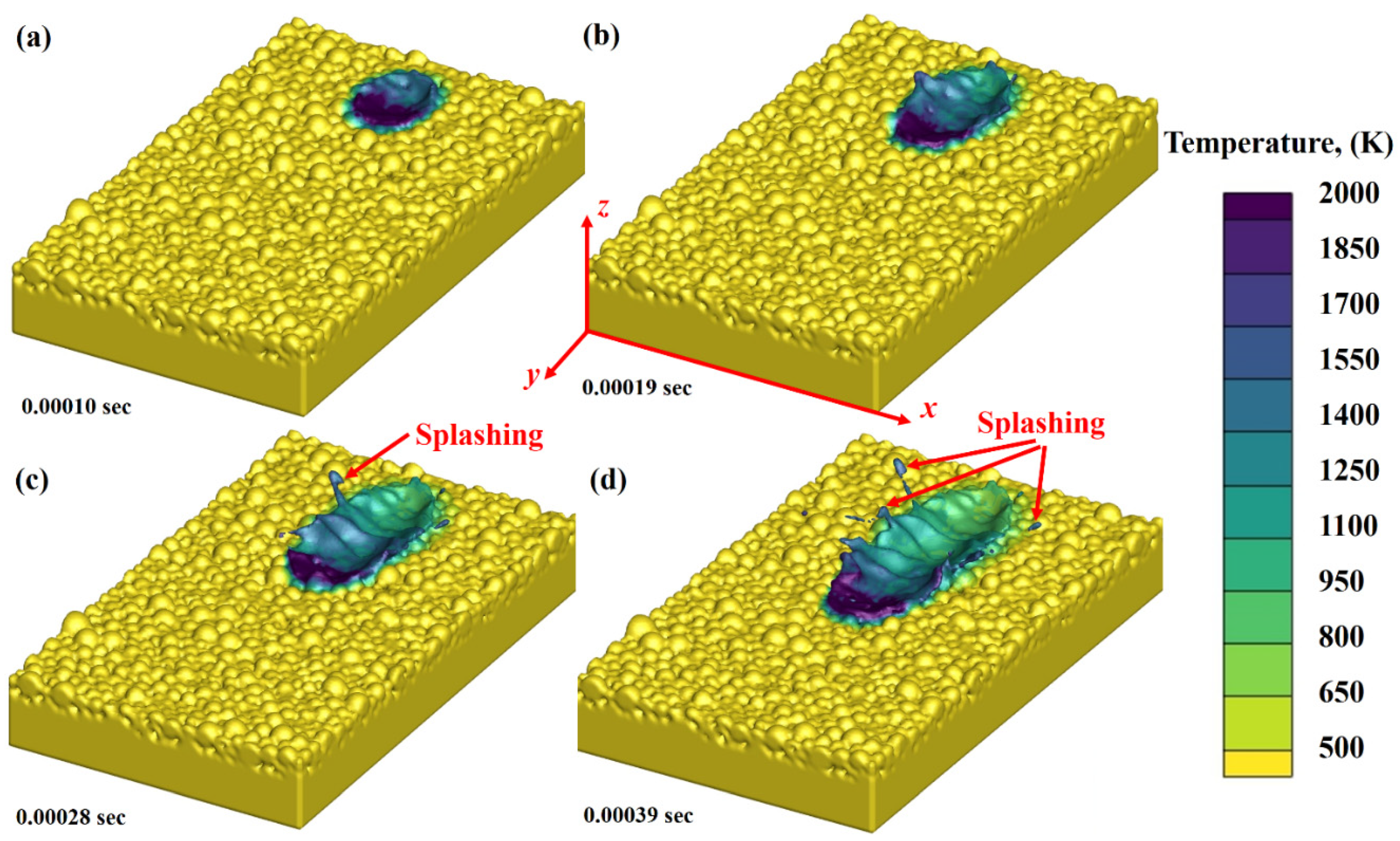
  • The development of small protrusions on the front keyhole wall, accompanied by the modification of the keyhole morphology, are referred to as event no. 01. A tiny protrusion appears along the rim of the front keyhole wall and runs down towards the keyhole bottom. After a few of these little protrusions, the keyhole transforms from a J-shaped to a reverse-triangle-shaped shape.
  • The development and evolution of a tongue-like protrusion from the front keyhole wall can be categorized as event no. 02. Following on from the little protrusions in the event no. 01, a second protrusion forms at the front keyhole wall rim and runs down. The protrusion’s velocity abruptly slows, and its shape changes from the initial dome leaning downward to a short rod tilting upward. The protrusion proliferates, with a deep and narrow mini-keyhole on top, and then stretches swiftly towards the horizontal center of the keyhole, generating a tongue-like protrusion that disappears in a microsecond, signifying an explosion-like collapse. The protrusion’s vestiges (i.e., the root section connected to the front keyhole wall) travel downward and disappear at the keyhole bottom.
Events 03 and 04, which occur concurrently, characterize the change in local curvature of the keyhole walls and the morphology of the melt around the upper keyhole rims, respectively. The local curvatures around the keyhole rims undergo quick alterations in the event no. 03, shortly following the spectacular collapse of the tongue-like protrusion described in the event no. 02. Meanwhile, the rear keyhole wall at the rim is rough and wrinkled, and the front keyhole wall is reasonably smooth. Thin melt ligaments arise from the rims (above or below the sample surface) at the event no. 04, then rise, neck, and break up into spatters at the end. The above-defined forces, events, operating conditions combined with the higher fluidity of AlSi10Mg alloy at elevated temperature are responsible for melt pool splashing during LPBF printing of AlSi10Mg alloy due to a higher laser–material interaction time.
Stream traces were used to identify the melt flow pattern and splashing within the melt pool. These results have been shown in Figure 4a–d for different time zones, including 0.00010 s, 0.00019 s, 0.00028 s and 0.0039 s, respectively. From the results, it can be identified that the melt flow usually follows a clockwise vortex ahead of the laser spot while an anti-clockwise vortex behind the laser spot.
The stream traces, with substrate and layer cutoff, within the melt flow were plotted in Figure 5a–d at 0.00010 s, 0.00019 s, 0.00028 s and 0.0039 s, respectively, to counter-verify the findings presented in Figure 3. It is clear from the stream traces that the melt flow adopts a clockwise vortex ahead of the laser beam while an anti-clockwise vortex behind the laser beam. Besides the splashing phenomenon as illustrated above, another mechanism is related to the motion of powder particles in the powder bed, known as “denudation.” Driven by the ambient gas flow induced by the jetting metal vapor, an “entrainment” zone is induced, where particles are entrained towards the jet hole. This entrainment zone is particularly long behind the moving vapor jet while short in the front. It is because the gas phase behind the moving vapor jet has dynamic motion, but that in front of the jet remains stationary. Particles close to the jet hole are dragged inward, resulting in two pieces of “denudation” zones beside the moving track of the vapor jet (i.e., the laser melt track in LPBF). Furthermore, some of the entrained particles are blown away by the vapor jet, and some are not, which thereby gather on the track, forming an “accumulation” zone. The accumulation zone is also influenced by the spattering phenomenon [66].
Figure 6a–d shows the material’s density change and melt flow mode across the cross-section along the y-axis at various time domains at 0.00010 s, 0.00019 s, 0.00028 s and 0.0039 s, respectively. The melt flow patterns can be classified into (a) conduction mode (CM) and (b) depression mode (DM) [67,68]. In CM, the material is heated from the top. The laser energy employed is usually higher than the heat loss rate that surpasses the material’s melting temperature, resulting in melt pool formation. The possibility of material vaporization lies in both CM and DM [69]. However, the material vaporization probability is very high in the case of DM exists at a higher laser energy density [70]. During laser printing, the bubbles escape from the melt pool and result in porosity if the solid front hits quickly before their escape. It is worth mentioning that the pores formation probability is much higher in DM than the CM due to higher energy density utilization in the case of DM. For AlSi10Mg, the laser beam absorptivity is only 18% [19]. The CM will transform into DM if the laser energy density absorption becomes significantly high. However, in this study, only CM has been identified. Furthermore, the simulation results presented three regions: (a) melt pool, (b) mushy zone and (c) solidified regime. The melt pool’s multi-physical dynamics and thermal distribution determine and control the microstructure evolution and corresponding mechanical-physical characteristics. The control of melt pool dynamics will ultimately assist in controlling the part’s characteristics at the layer level.
The y-axis cross-sections of liquid-solid transformation for different simulation time domains, at 0.00010 s, 0.00019 s, 0.00028 s and 0.0039 s, are shown in Figure 7a–d. It can be concluded that when the laser beam heats the material, the powder layer changes the phase from solid to liquid. As the laser beam moves away, the heat from the irradiated zone starts to dissipate in the substrate and surrounding by conduction, convection and radiation, resulting in material solidification. This process continues until the entire layer is printed.
Figure 8 displays the optical image of the twenty samples of AlSi10Mg alloy fabricated by LPBF process. One can observe that the samples are in cylindrical shapes having 10 mm diameter and 80 mm length. The manufactured samples were cut in the dimensions of 2.5 (mm) × 10 (mm) × 50 (mm). Following on these samples were ground and polished to analyze microstructure.
The microstructure of 20 samples has been presented in Figure 9. The microstructure identified three types of defects in the LPBF-ed AlSi10Mg alloy, including cracks, poor binding, porosity and unmelted region. The primary factors involved in the LPBF printing process are laser power, laser scanning speed, hatch spacing, layer thickness, powder materials and chamber environment. The defects usually occur when any of the parameters are chosen incorrectly. When the metallic powders with a hollow structure are used in an LPBF process, porosities typically occur. On the other hand, the melt pool temperature is often high due to the rapid heating and slow conduction. At this temperature, the gas solubility in the melted liquid is very high. Furthermore, gas is inadvertently introduced into powder materials during the preparation process, particularly gas atomized powder materials protected by an inert gas such as argon or helium [71,72]. Another significant source of porosities in LPBF is the keyhole induced porosities. Such pores are mainly generated due to local cold zones formation with high surface tension and low rebound pressure. Furthermore, as the keyhole forms, the pores may float and try to escape from the free surface of the liquid metal, join with other pores and increase in volume, or even blend with the keyhole’s wake and disappear [73].
Porosity was identified in S1, S3, S4, S6, S8, S9, S10, S12, S13, S16, S17, S18 and S19 samples, as shown in Figure 9. It is worth mentioning that the porosity (%) is relatively less in the case of S8, S13, S16, S17, S18 and S19 samples compared to the rest of the samples.
The lack of energy input during the LPBF printing process causes incomplete fusion, designated as lack of fusion (LOF) defects. In LOF, poor bonding and unmelted region are the two types of LOF defects. In the LPBF process, a laser beam selectively melts metallic powder particles. The width of the molten pool is small when the laser energy input is minimal, resulting from insufficient overlap between the tracks. An inadequate overlap between the layers causes the formation of the unmelted regions between the scan tracks. It becomes extremely difficult to remelt these powders while depositing a new layer. As a result, partial fusion holes emerge in the LPBF-fabricated part. If the laser energy input is insufficient to generate sufficient molten pool penetration depth, LOF faults may result from weak interlayer bonding. As a result, LOF errors are commonly seen in the scan tracks and deposited layers. In addition, the surface of a site where faults have been formed becomes rough. The rough surface contributes directly to the molten metal’s poor flow, resulting in interlayer flaws. In a continuous deposition process, interlayer faults may gradually spread and propagate upwards to generate massive multi-layer flaws [71,72]. The samples S2, S7, S11 and S20, in Figure 9, showed the defects due to unmelted regions, while the sample S5 presented defects owing to the poor bonding, resulting due to LOF, but can be either caused by low energy input, or presence of the secondary phases (oxides), as well as hydrogen porosity that is typical for LPBF of Al-alloys [74,75].
In LPBF printing, metallic powders usually experience rapid heating, melting and solidification due to localized heat energy input. In LPBF, the melt pool usually cools down at 108 K/s, resulting in a substantial thermal gradient, thus causing thermal stress formation in the produced samples. In the fabricated parts, cracks’ commencement and proliferation are caused by a robust thermal gradient lined with high residual stresses [71,72]. The crack morphology in the LPBF parts can be identified in samples S5 and S14 (Figure 9). It is worth mentioning that the cracks are more likely to start on the as-built surface, which is attached with partially melted metallic powder particles.
From the visual inspection and optical images results, one can identify that operating conditions for sample S15 presented microstructure without defects. Hence, it can be concluded that the operating parameters for specimen S15 are optimum conditions.
To mitigate all the defects in LPBF process, one of the commonly used approaches is to conduct parameters mapping for process optimization [76]. Process mapping helps to identify the safe regions from different pores and defects in different LPBF process parameters. Another effective approach is to develop a simulation model for LPBF process. Various simulation techniques are available in the literature, including finite element and analytical simulation [39,48,77]. These simulation models help identify the optimum operating conditions by eliminating the parameters responsible for keyhole-based porosities, lack of fusion defects, and unmelted regions before carrying out actual experiments.

5. Conclusions

In this study analytical and computational fluid dynamics (CFD) models have been deduced in the case of AlSi10Mg alloy LPBF. For analytical modelling, the dimensions of single deposited layer have been estimated using primary operating conditions. In the case of CFD model, the volume of fluid and discrete element modelling techniques have been applied to illustrate the splashing and spatter phenomena for LPBF of AlSi10Mg alloy, thus presenting a novel AlSi10Mg hydrodynamics model for laser–powder bed interaction. The computational results have been compared with experimental analyses. In addition, a trial-and-error method was applied to select an optimized set of parameters for LPBF of AlSi10Mg alloy. The primary operating conditions, including laser scanning speed, laser spot diameter and laser power were varied, while the powder layer thickness and hatch distance were kept fixed. By using this strategy, 20 samples were fabricated and cut in the form of cubes with the dimensions of 2.5 (mm) × 10 (mm) × 50 (mm). Following on, the samples’ microstructures were analyzed using microscope. Based on the analyses results, an optimized set of parameters was defined to attain defect free parts. The following conclusions have been deduced based on the current study:
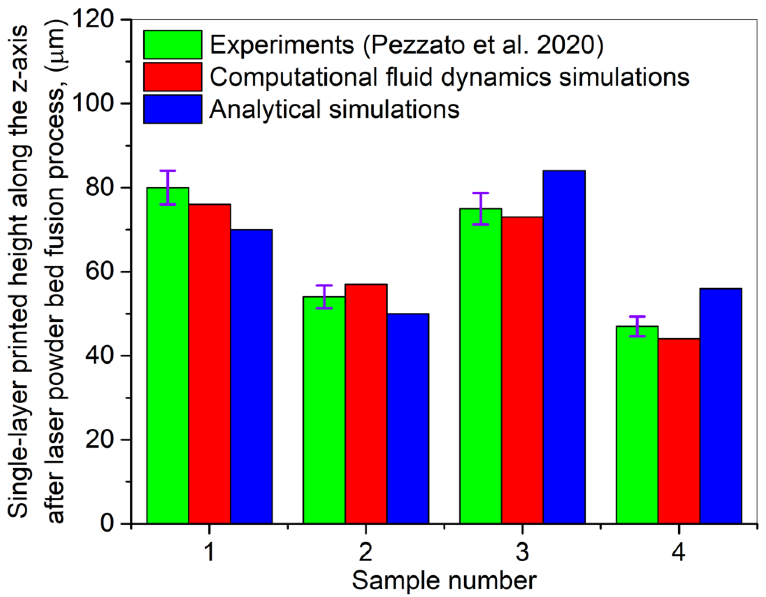
  • It was found that the CFD and analytical computations generated results with a deviation of 2–4% and 7–10%, respectively, compared to the experimental results.
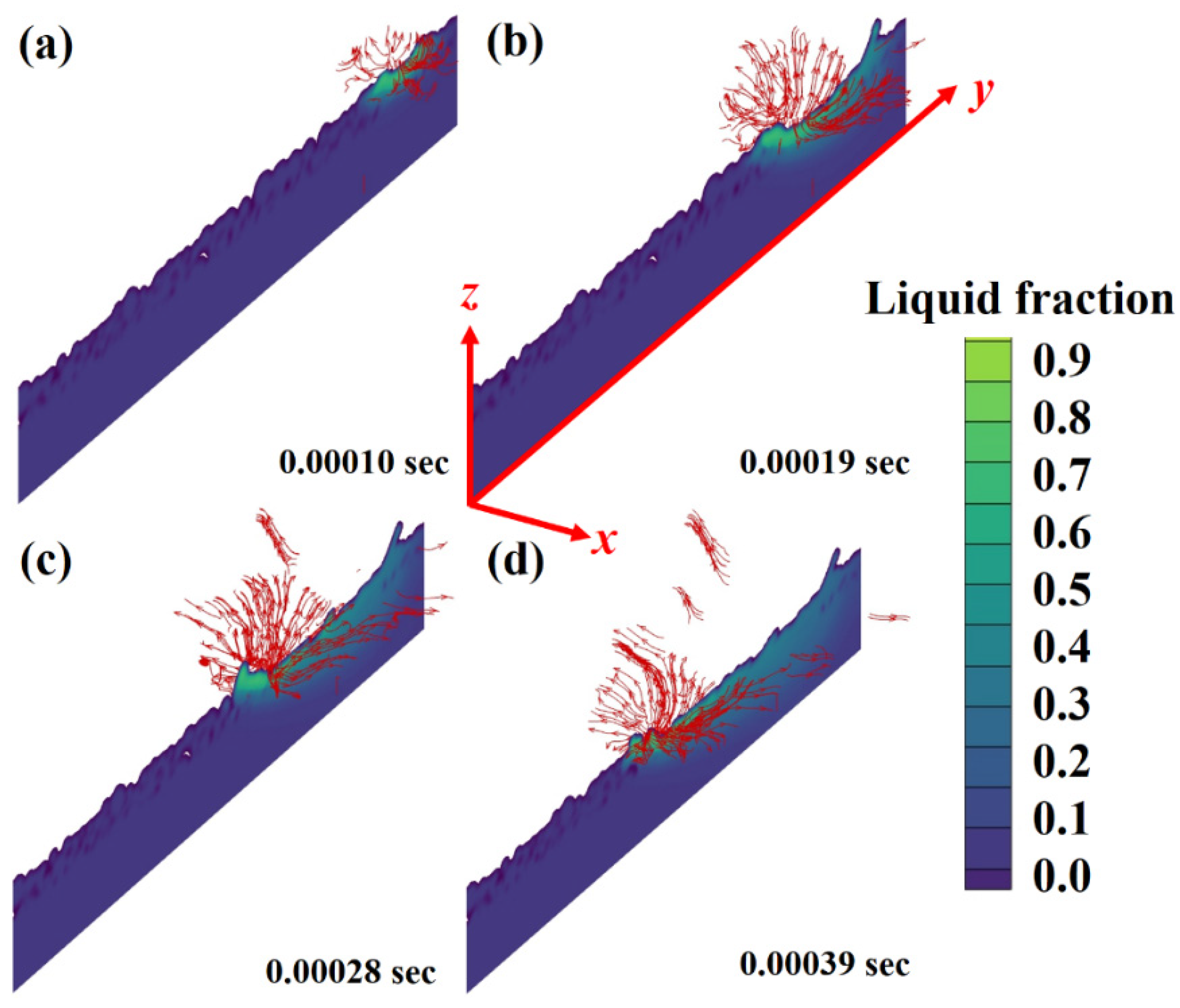
  • Laser–material interaction time plays a critical role in controlling the Marangoni flow, vaporization, high-speed vapor cloud, hydraulic pressure and buoyancy. As the laser- AlSi10Mg material interaction increases, it transforms the solid material into a liquid one, which in re-turn dominates the forces mentioned above. A combination of elevated laser–material interaction time, the transformation of keyhole from J-shape to reverse triangle-shape, the tongue-like protrusion in the keyhole and dominancy of Marangoni flow, vaporization, high-speed vapor cloud, Hydraulic pressure and buoyancy lead to splashing in the AlSi10Mg material.
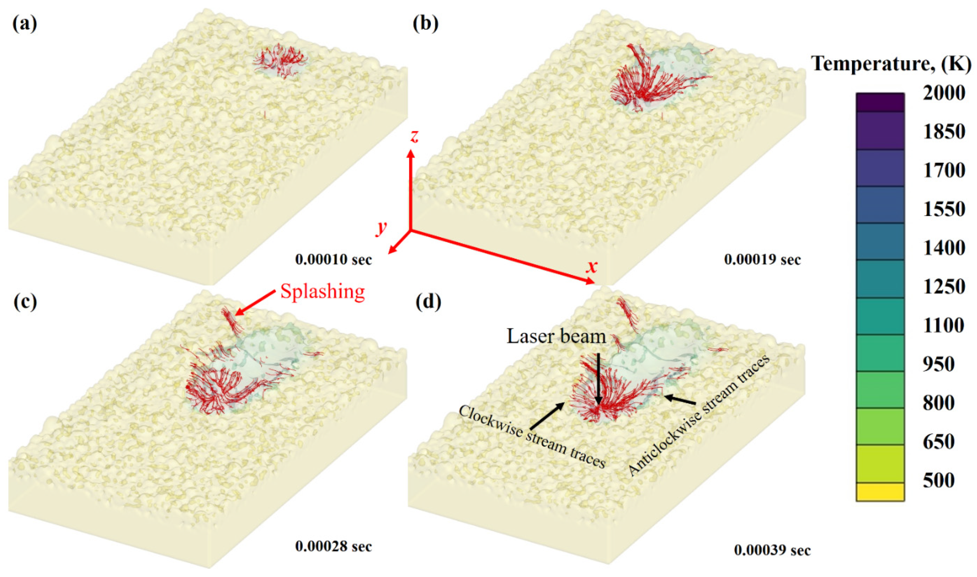
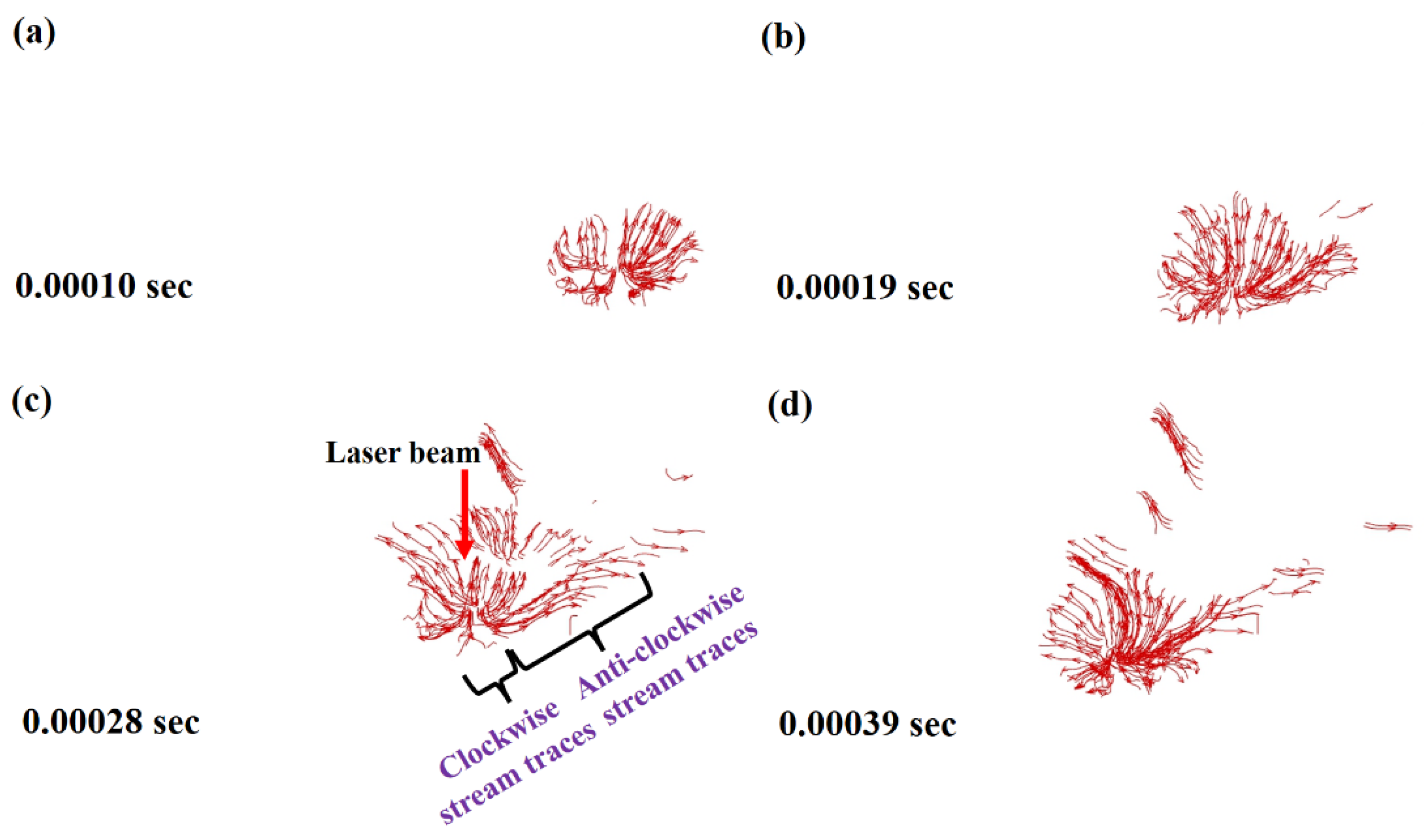
  • According to the simulation results, the melt flow normally follows a clockwise vortex in front of the laser beam and an anti-clockwise vortex behind the laser beam spot.
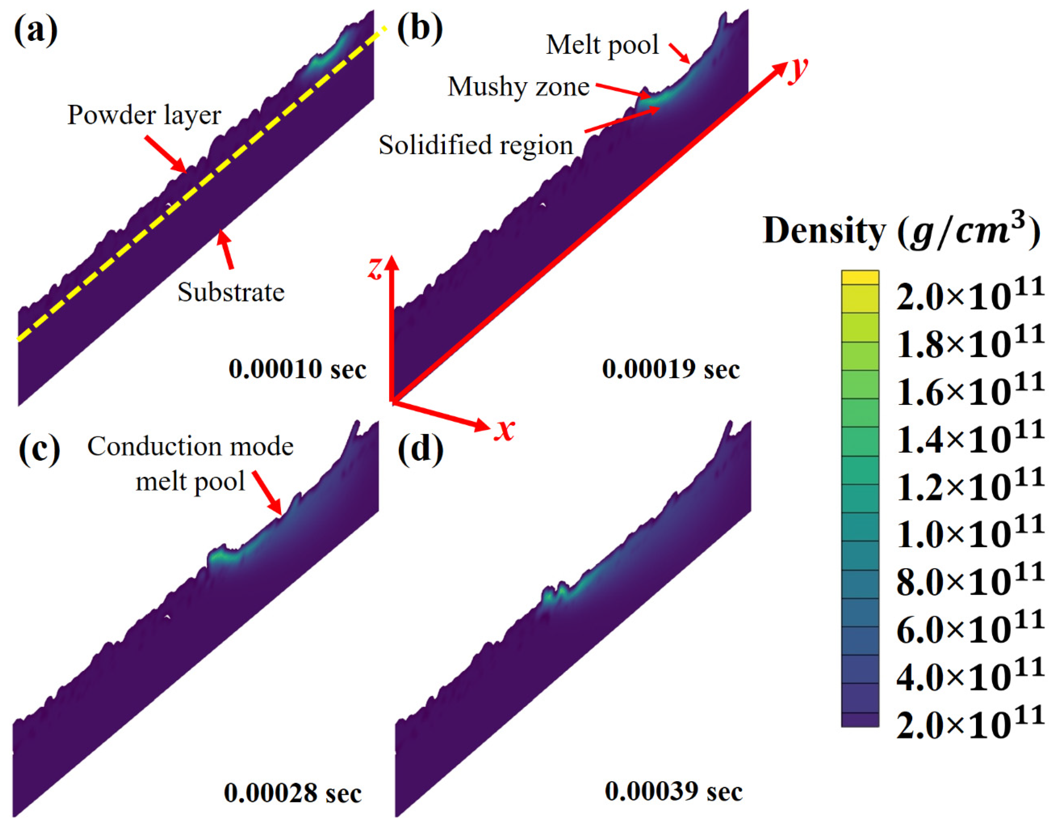
  • The melt pattern can be classified into conduction mode and depression mode. The probability of pores formation is much higher in the case of depression mode. However, in LPBF printing of AlSi10Mg, only conduction mode melt flow has been identified due to 18% laser beam absorption coefficient.
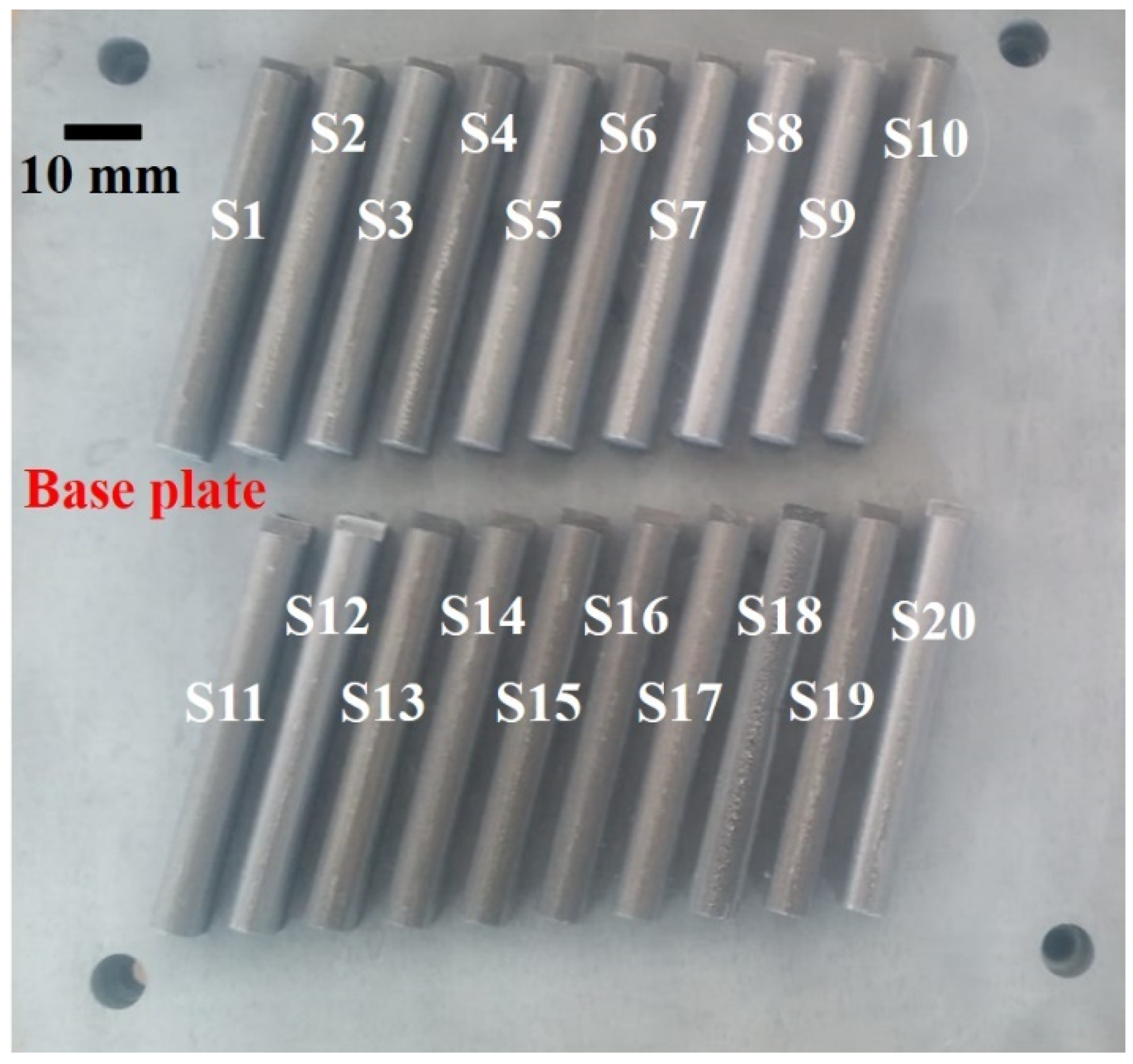
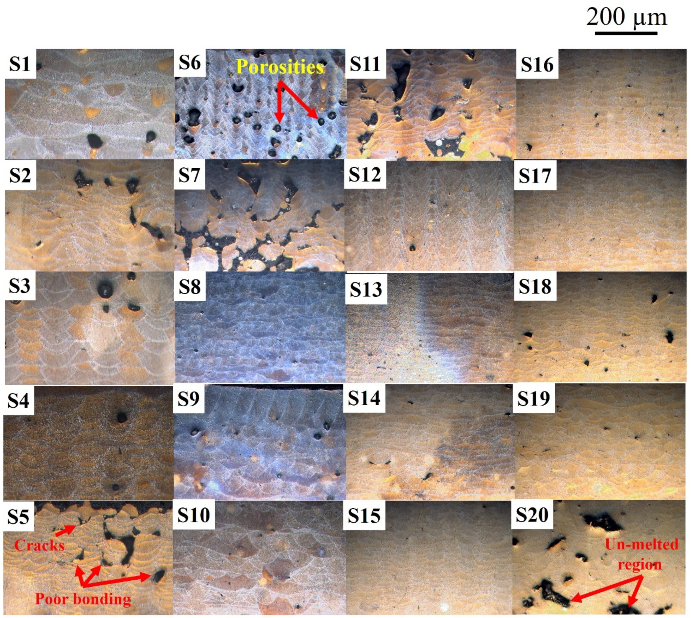
  • For multi-layers printing, 20 AlSi10Mg samples were printed using the LPBF technique. Through optical images and visual inspections, it was identified that the samples presented defects, including cracks, poor binding, keyhole induced porosity and unmelted region. Additionally, low energy input, the presence of the secondary phases (oxides), and the hydrogen porosity typical for LPBF of Al-alloys are responsible for the defects mentioned above. Such defects were identified in all the samples except sample S15 having operating conditions: laser power = 140 W, (b) laser spot diameter = 180 µm, (c) laser scanning speed = 0.6 m/s, powder layer thickness = 0.5 µm and hatch distance = 112 µm.
This study provides cost- and time-effective tools to optimize the operating conditions before real experimentation. The analytical model can be used to estimate the dimensions of the printed layer and thermal distribution necessary to melt the material entirely, based on the provided operating conditions. The developed dynamic CFD model can be further applied to explore the AlSi10Mg hydrodynamics by varying the operating conditions. In addition, the selected optimized set of parameters can be utilized to develop mechanical properties of AlSi10Mg alloy.

Author Contributions

Conceptualization, methodology, A.U.R. and M.A.M.; formal analysis, A.U.R., M.A.M., P.A., F.P., M.U.S., A.C.P. and I.N.M.; investigation, A.U.R., M.A.M. and P.A.; writing—original draft preparation A.U.R. and M.A.M.; writing—review and editing, A.U.R., M.A.M., P.A., F.P., M.U.S., A.C.P. and I.N.M.; supervision, A.U.R., M.A.M., F.P., M.U.S., A.C.P. and I.N.M.; project administration, A.U.R., M.A.M., F.P., M.U.S. and I.N.M.; resources, funding acquisition, A.U.R., M.A.M., F.P., M.U.S. and I.N.M. All authors have read and agreed to the published version of the manuscript.

Funding

A.U.R. and M.A.M., have received financial support from the European Union’s Horizon 2020 (H2020) research and innovation program under the Marie Skłodowska-Curie, grant agreement No. 764935. This project has received financial support from the European Union’s Horizon 2020 (H2020) research and innovation program under the Marie Skłodowska-Curie grant, agreement No. 764935. This research has been conducted in the framework of POC-G Contract no. 135/2016 and UEFISCDI 45/2021. This work was also supported by grants of the Romanian Ministry of Education and Research, CNCS-UEFISCDI, project number PN-III-P4-ID-PCE-2020-1634, PN-III-P2-2-1-PED-2019-3953, within PNCDI III, and Romanian Ministry of Education and Research, under Romanian National Nucleu Program LAPLAS VI–contract no. 16N/2019.

Institutional Review Board Statement

Not applicable.

Informed Consent Statement

Not applicable.

Data Availability Statement

Not applicable.

Acknowledgments

The kind assistance of Anil Ummet Yanalak for OM is also acknowledged. The support from the Turkish Aerospace for the CFD post-processing is also duly acknowledged. The authors acknowledge with thanks the European Union’s Horizon 2020 (H2020) research and innovation program, under the Marie Skłodowska-Curie, grant agreement No. 764935., POC-G Contract no. 135/2016, UEFISCDI 45/2021, Romanian Ministry of Education and Research, CNCS-UEFISCDI, project number PN-III-P4-ID-PCE-2020-1634, PN-III-P2-2-1-PED-2019-3953, within PNCDI III, and Romanian Ministry of Education and Research, under Romanian National Nucleu Program LAPLAS VI–contract no. 16N/2019.

Conflicts of Interest

The authors declare no conflict of interest.

References

  1. Kok, Y.; Tan, X.P.; Wang, P.; Nai, M.L.S.; Loh, N.H.; Liu, E.; Tor, S.B. Anisotropy and heterogeneity of microstructure and mechanical properties in metal additive manufacturing: A critical review. Mater. Des. 2018, 139, 565–586. [Google Scholar] [CrossRef]
  2. Guo, N.; Leu, M.C. Additive manufacturing: Technology, applications and research needs. Front. Mech. Eng. 2013, 8, 215–243. [Google Scholar] [CrossRef]
  3. Tiwari, S.K.; Pande, S.; Agrawal, S.; Bobade, S.M. Selection of selective laser sintering materials for different applications. Rapid Prototyp. J. 2015, 21, 630–648. [Google Scholar] [CrossRef]
  4. Liu, F.H. Synthesis of bioceramic scaffolds for bone tissue engineering by rapid prototyping technique. J. Sol-Gel Sci. Technol. 2012, 64, 704–710. [Google Scholar] [CrossRef]
  5. Mahmood, M.A. 3D printing in drug delivery and biomedical applications: A state-of-the-art review. Compounds 2021, 1, 94–115. [Google Scholar] [CrossRef]
  6. Ur Rehman, A.; Sglavo, V.M. 3D printing of geopolymer-based concrete for building applications. Rapid Prototyp. J. 2020, 26, 1783–1788. [Google Scholar] [CrossRef]
  7. Ur Rehman, A.; Sglavo, V.M. 3D printing of Portland cement-containing bodies. Rapid Prototyp. J. 2021. ahead of print. [Google Scholar] [CrossRef]
  8. Ur Rehman, A.; Liu, T.; Liao, W. 4D Printing; Printing Ceramics from Metals with Selective Oxidation. WIPO Patent no. WO2019052128A1, 2019. [Google Scholar]
  9. Rehman, A.U.; Liu, T. Additive Manufacturing of Ceramic Materials and Combinations with New Laser Strategies. Master’s Thesis, Nanjing University of Science and Technology, Nanjing, China, 2017. [Google Scholar]
  10. Zhang, J.; Song, B.; Wei, Q.; Bourell, D.; Shi, Y. A review of selective laser melting of aluminum alloys: Processing, microstructure, property and developing trends. J. Mater. Sci. Technol. 2019, 35, 270–284. [Google Scholar] [CrossRef]
  11. Ansari, P.; Salamci, M.U. On the selective laser melting based additive manufacturing of AlSi10Mg: The process parameter investigation through multiphysics simulation and experimental validation. J. Alloys Compd. 2022, 890, 161873. [Google Scholar] [CrossRef]
  12. DebRoy, T.; Wei, H.L.; Zuback, J.S.; Mukherjee, T.; Elmer, J.W.; Milewski, J.O.; Beese, A.M.; Wilson-Heid, A.; De, A.; Zhang, W. Additive manufacturing of metallic components—Process, structure and properties. Prog. Mater. Sci. 2018, 92, 112–224. [Google Scholar] [CrossRef]
  13. Mukherjee, T.; Wei, H.L.; De, A.; DebRoy, T. Heat and fluid flow in additive manufacturing—Part I: Modeling of powder bed fusion. Comput. Mater. Sci. 2018, 150, 304–313. [Google Scholar] [CrossRef] [Green Version]
  14. Ur Rehman, A.; Pitir, F. Full-field mapping and flow quantification of melt pool dynamics in laser powder bed fusion of SS316L. Materials 2021, 14, 6264. [Google Scholar] [CrossRef]
  15. Mahmood, M.A.; Popescu, A.C. 3D printing at micro-level: Laser induced forward transfer and two-photon polymerization. Polymers 2021, 13, 2034. [Google Scholar] [CrossRef]
  16. Ullah, A.; Wu, H.A.; Ur Rehman, A.; Zhu, Y.B.; Liu, T.; Zhang, K. Influence of laser parameters and Ti content on the surface morphology of L-PBF fabricated Titania. Rapid Prototyp. J. 2020, 27, 71–80. [Google Scholar] [CrossRef]
  17. Shi, X.; Ma, S.; Liu, C.; Wu, Q. Parameter optimization for Ti-47Al-2Cr-2Nb in selective laser melting based on geometric characteristics of single scan tracks. Opt. Laser Technol. 2017, 90, 71–79. [Google Scholar] [CrossRef]
  18. Liu, S.; Zhu, H.; Peng, G.; Yin, J.; Zeng, X. Microstructure prediction of selective laser melting AlSi10Mg using finite element analysis. Mater. Des. 2018, 142, 319–328. [Google Scholar] [CrossRef]
  19. Liu, B.; Li, B.Q.; Li, Z.; Bai, P.; Wang, Y.; Kuai, Z. Numerical investigation on heat transfer of multi-laser processing during selective laser melting of AlSi10Mg. Results Phys. 2019, 12, 454–459. [Google Scholar] [CrossRef]
  20. Han, Q.; Setchi, R.; Lacan, F.; Gu, D.; Evans, S.L. Selective laser melting of advanced Al-Al2O3 nanocomposites: Simulation, microstructure and mechanical properties. Mater. Sci. Eng. A 2017, 698, 162–173. [Google Scholar] [CrossRef]
  21. Liu, S.; Zhu, J.; Zhu, H.; Yin, J.; Chen, C.; Zeng, X. Effect of the track length and track number on the evolution of the molten pool characteristics of SLMed Al alloy: Numerical and experimental study. Opt. Laser Technol. 2020, 123, 105924. [Google Scholar] [CrossRef]
  22. Li, Y.; Gu, D. Parametric analysis of thermal behavior during selective laser melting additive manufacturing of aluminum alloy powder. Mater. Des. 2014, 63, 856–867. [Google Scholar] [CrossRef]
  23. Du, Y.; You, X.; Qiao, F.; Guo, L.; Liu, Z. A model for predicting the temperature field during selective laser melting. Results Phys. 2019, 12, 52–60. [Google Scholar] [CrossRef]
  24. Ur Rehman, A.; Mahmood, M.A.; Pitir, F.; Salamci, M.U.; Popescu, A.C.; Mihailescu, I.N. Mesoscopic computational fluid dynamics modelling for the laser-melting deposition of AISI 304 stainless steel single tracks with experimental correlation: A novel study. Metals 2021, 11, 1569. [Google Scholar] [CrossRef]
  25. Ur Rehman, A.; Mahmood, M.A.; Pitir, F.; Salamci, M.U.; Popescu, A.C.; Mihailescu, I.N. Keyhole formation by laser drilling in laser powder bed fusion of Ti6Al4V biomedical alloy: Mesoscopic computational fluid dynamics simulation versus mathematical modelling using empirical validation. Nanomaterials 2021, 11, 3284. [Google Scholar] [CrossRef]
  26. Oane, M.; Mahmood, M.A.; Popescu, A.C. A state-of-the-art review on integral transform technique in laser–material interaction: Fourier and non-Fourier heat equations. Materials 2021, 14, 4733. [Google Scholar] [CrossRef] [PubMed]
  27. Matthews, M.J.; Guss, G.; Khairallah, S.A.; Rubenchik, A.M.; Depond, P.J.; King, W.E. Denudation of metal powder layers in laser powder bed fusion processes. Acta Mater. 2016, 114, 33–42. [Google Scholar] [CrossRef] [Green Version]
  28. Ly, S.; Rubenchik, A.M.; Khairallah, S.A.; Guss, G.; Matthews, M.J. Metal vapor micro-jet controls material redistribution in laser powder bed fusion additive manufacturing. Sci. Rep. 2017, 7, 4085. [Google Scholar] [CrossRef] [PubMed]
  29. Zhao, C.; Guo, Q.; Li, X.; Parab, N.; Fezzaa, K.; Tan, W.; Chen, L.; Sun, T. Bulk-explosion-induced metal spattering during laser processing. Phys. Rev. X 2019, 9, 021052. [Google Scholar] [CrossRef] [Green Version]
  30. Mohsin Raza, M.; Lo, Y.L. Experimental investigation into microstructure, mechanical properties, and cracking mechanism of IN713LC processed by laser powder bed fusion. Mater. Sci. Eng. A 2021, 819, 141527. [Google Scholar] [CrossRef]
  31. Wang, H.Y.; Lo, Y.L.; Tran, H.C.; Raza, M.M.; Le, T.N. Systematic approach for reducing micro-crack formation in Inconel 713LC components fabricated by laser powder bed fusion. Rapid Prototyp. J. 2021, 27, 1548–1561. [Google Scholar] [CrossRef]
  32. Reza, A.; Dezfoli, A.; Lo, Y.-L.; Mohsin Raza, M. 3D multi-track and multi-layer epitaxy grain growth simulations of selective laser melting. Materials 2021, 14, 7346. [Google Scholar] [CrossRef]
  33. Dezfoli, A.R.A.; Lo, Y.L.; Raza, M.M. Prediction of epitaxial grain growth in single-track laser melting of IN718 using integrated finite element and cellular automaton approach. Materials 2021, 14, 5202. [Google Scholar] [CrossRef]
  34. Dezfoli, A.R.A.; Lo, Y.L.; Mohsin Raza, M. Microstructure and elements concentration of Inconel 713LC during laser powder bed fusion through a modified cellular automaton model. Crystals 2021, 11, 1065. [Google Scholar] [CrossRef]
  35. Mukherjee, T.; Wei, H.L.; De, A.; DebRoy, T. Heat and fluid flow in additive manufacturing—Part II: Powder bed fusion of stainless steel, and titanium, nickel and aluminum base alloys. Comput. Mater. Sci. 2018, 150, 369–380. [Google Scholar] [CrossRef]
  36. Pei, W.; Zhengying, W.; Zhen, C.; Junfeng, L.; Shuzhe, Z.; Jun, D. Numerical simulation and parametric analysis of selective laser melting process of AlSi10Mg powder. Appl. Phys. A Mater. Sci. Process. 2017, 123, 540. [Google Scholar] [CrossRef]
  37. Courtois, M.; Carin, M.; Le Masson, P.; Gaied, S.; Balabane, M. A new approach to compute multi-reflections of laser beam in a keyhole for heat transfer and fluid flow modelling in laser welding. J. Phys. D Appl. Phys. 2013, 46, 215301. [Google Scholar] [CrossRef]
  38. Ansari, P.; Rehman, A.U.; Pitir, F.; Veziroglu, S.; Mishra, Y.K.; Aktas, O.C.; Salamci, M.U. Selective laser melting of 316l austenitic stainless steel: Detailed process understanding using multiphysics simulation and experimentation. Metals 2021, 11, 1076. [Google Scholar] [CrossRef]
  39. Mahmood, M.A.; Popescu, A.C.; Oane, M.; Ristoscu, C.; Chioibasu, D.; Mihai, S.; Mihailescu, I.N. Three-jet powder flow and laser–powder interaction in laser melting deposition: Modelling versus experimental correlations. Metals 2020, 10, 1113. [Google Scholar] [CrossRef]
  40. Diniz Neto, O.O.; Vilar, R. Physical–computational model to describe the interaction between a laser beam and a powder jet in laser surface processing. J. Laser Appl. 2002, 14, 46–51. [Google Scholar] [CrossRef]
  41. Lepski, D.; Brückner, F. Laser cladding. In The Theory of Laser Materials Processing; Springer: Dordrecht, The Netherlands, 2017; pp. 235–279. [Google Scholar]
  42. Available online: https://en.wikipedia.org/wiki/Enthalpy_of_fusion (accessed on 1 December 2020).
  43. Available online: https://en.wikipedia.org/wiki/Specific_heat_capacity (accessed on 1 December 2020).
  44. Mahmood, M.A.; Popescu, A.C.; Oane, M.; Channa, A.; Mihai, S.; Ristoscu, C.; Mihailescu, I.N. Bridging the analytical and artificial neural network models for keyhole formation with experimental verification in laser melting deposition: A novel approach. Results Phys. 2021, 26, 104440. [Google Scholar] [CrossRef]
  45. RP Photonics Encyclopedia—Optical Intensity, Physics, Radiometry, Energy Flux, Light Intensity, Amplitude, Electric Field, Poynting Vector. Available online: https://www.rp-photonics.com/optical_intensity.html (accessed on 29 April 2020).
  46. Iacobescu, G. A theoretical model for welding process with gaussian heat source—Part 1. Univ. Politeh. Buchar. Sci. Bull. Ser. D 2006, 68, 45–50. [Google Scholar]
  47. Erf—From Wolfram MathWorld. Available online: https://mathworld.wolfram.com/Erf.html (accessed on 20 November 2020).
  48. Mahmood, M.A.; Popescu, A.C.; Hapenciuc, C.L.; Ristoscu, C.; Visan, A.I.; Oane, M.; Mihailescu, I.N. Estimation of clad geometry and corresponding residual stress distribution in laser melting deposition: Analytical modeling and experimental correlations. Int. J. Adv. Manuf. Technol. 2020, 111, 77–91. [Google Scholar] [CrossRef]
  49. Cleary, P.W.; Sawley, M.L. DEM modelling of industrial granular flows: 3D case studies and the effect of particle shape on hopper discharge. Appl. Math. Model. 2002, 26, 89–111. [Google Scholar] [CrossRef]
  50. Parteli, E.J.R.; Pöschel, T. Particle-based simulation of powder application in additive manufacturing. Powder Technol. 2016, 288, 96–102. [Google Scholar] [CrossRef]
  51. Cao, L. Numerical simulation of the impact of laying powder on selective laser melting single-pass formation. Int. J. Heat Mass Transf. 2019, 141, 1036–1048. [Google Scholar] [CrossRef]
  52. Tian, Y.; Yang, L.; Zhao, D.; Huang, Y.; Pan, J. Numerical analysis of powder bed generation and single track forming for selective laser melting of SS316L stainless steel. J. Manuf. Process. 2020, 58, 964–974. [Google Scholar] [CrossRef]
  53. Lee, Y.S.; Zhang, W. Modeling of heat transfer, fluid flow and solidification microstructure of nickel-base superalloy fabricated by laser powder bed fusion. Addit. Manuf. 2016, 12, 178–188. [Google Scholar] [CrossRef] [Green Version]
  54. Tang, M.; Pistorius, P.C.; Beuth, J.L. Prediction of lack-of-fusion porosity for powder bed fusion. Addit. Manuf. 2017, 14, 39–48. [Google Scholar] [CrossRef]
  55. Promoppatum, P.; Yao, S.C.; Pistorius, P.C.; Rollett, A.D. A Comprehensive comparison of the analytical and numerical prediction of the thermal history and solidification microstructure of Inconel 718 products made by laser powder-bed fusion. Engineering 2017, 3, 685–694. [Google Scholar] [CrossRef]
  56. Rosenthal, D. Mathematical theory of heat distribution during welding and cutting. Weld. J. 1941, 20, 220–234. [Google Scholar]
  57. Chen, Q.; Zhao, Y.; Strayer, S.; Zhao, Y.; Aoyagi, K.; Koizumi, Y.; Chiba, A.; Xiong, W.; To, A.C. Elucidating the effect of preheating temperature on melt pool morphology variation in Inconel 718 laser powder bed fusion via simulation and experiment. Addit. Manuf. 2020, 37, 101642. [Google Scholar] [CrossRef]
  58. Pezzato, L.; Dabalà, M.; Gross, S.; Brunelli, K. Effect of microstructure and porosity of AlSi10Mg alloy produced by selective laser melting on the corrosion properties of plasma electrolytic oxidation coatings. Surf. Coat. Technol. 2020, 404, 126477. [Google Scholar] [CrossRef]
  59. Al-Si10-Mg|Advanced Powders. Available online: https://www.advancedpowders.com/powders/aluminum/al-si10-mg (accessed on 4 October 2021).
  60. Pauzon, C.; Hryha, E.; Forêt, P.; Nyborg, L. Effect of argon and nitrogen atmospheres on the properties of stainless steel 316 L parts produced by laser-powder bed fusion. Mater. Des. 2019, 179, 107873. [Google Scholar] [CrossRef]
  61. AlMgSi Alloys: Total Materia Article. Available online: https://www.totalmateria.com/page.aspx?ID=CheckArticle&site=ktn&NM=348 (accessed on 30 September 2021).
  62. Paul, A.; Debroy, T. Free surface flow and heat transfer in conduction mode laser welding. Metall. Trans. B 1988, 19, 851–858. [Google Scholar] [CrossRef]
  63. Aucott, L.; Dong, H.; Mirihanage, W.; Atwood, R.; Kidess, A.; Gao, S.; Wen, S.; Marsden, J.; Feng, S.; Tong, M.; et al. Revealing internal flow behaviour in arc welding and additive manufacturing of metals. Nat. Commun. 2018, 9, 5414. [Google Scholar] [CrossRef] [PubMed] [Green Version]
  64. Abderrazak, K.; Bannour, S.; Mhiri, H.; Lepalec, G.; Autric, M. Numerical and experimental study of molten pool formation during continuous laser welding of AZ91 magnesium alloy. Comput. Mater. Sci. 2009, 44, 858–866. [Google Scholar] [CrossRef]
  65. Fabbro, R.; Dal, M.; Peyre, P.; Coste, F.; Schneider, M.; Gunenthiram, V. Analysis and possible estimation of keyhole depths evolution, using laser operating parameters and material properties. J. Laser Appl. 2018, 30, 032410. [Google Scholar] [CrossRef]
  66. Chen, H.; Yan, W. Spattering and denudation in laser powder bed fusion process: Multiphase flow modelling. Acta Mater. 2020, 196, 154–167. [Google Scholar] [CrossRef]
  67. Guo, Q.; Zhao, C.; Qu, M.; Xiong, L.; Hojjatzadeh, S.M.H.; Escano, L.I.; Parab, N.D.; Fezzaa, K.; Sun, T.; Chen, L. In-situ full-field mapping of melt flow dynamics in laser metal additive manufacturing. Addit. Manuf. 2020, 31, 100939. [Google Scholar] [CrossRef]
  68. Messler, J.R.W. Principles of Welding: Processes, Physics, Chemistry, and Metallurgy; John Wiley & Sons: New York, NY, USA, 2008; ISBN 3527617493/9783527617494. [Google Scholar]
  69. Cunningham, R.; Zhao, C.; Parab, N.; Kantzos, C.; Pauza, J.; Fezzaa, K.; Sun, T.; Rollett, A.D. Keyhole threshold and morphology in laser melting revealed by ultrahigh-speed X-ray imaging. Science 2019, 363, 849–852. [Google Scholar] [CrossRef] [PubMed]
  70. Sabin, M.; Chioibasu, D.; Mahmood, M.A.; Duta, L.; Leparoux, M.; Popescu, A.C. Real-time defects analyses using high speed imaging during aluminum magnesium alloy laser welding. Metals 2021, 11, 1877. [Google Scholar] [CrossRef]
  71. Zhang, B.; Li, Y.; Bai, Q. Defect formation mechanisms in selective laser melting: A review. Chin. J. Mech. Eng. 2017, 30, 515–527. [Google Scholar] [CrossRef] [Green Version]
  72. Aboulkhair, N.T.; Everitt, N.M.; Ashcroft, I.; Tuck, C. Reducing porosity in AlSi10Mg parts processed by selective laser melting. Addit. Manuf. 2014, 1, 77–86. [Google Scholar] [CrossRef]
  73. Bayat, M.; Thanki, A.; Mohanty, S.; Witvrouw, A.; Yang, S.; Thorborg, J.; Tiedje, N.S.; Hattel, J.H. Keyhole-induced porosities in Laser-based Powder Bed Fusion (L-PBF) of Ti6Al4V: High-fidelity modelling and experimental validation. Addit. Manuf. 2019, 30, 100835. [Google Scholar] [CrossRef]
  74. Fiegl, T.; Franke, M.; Raza, A.; Hryha, E.; Körner, C. Effect of AlSi10Mg0.4 long-term reused powder in PBF-LB/M on the mechanical properties. Mater. Des. 2021, 212, 110176. [Google Scholar] [CrossRef]
  75. Raza, A.; Fiegl, T.; Hanif, I.; MarkstrÖm, A.; Franke, M.; Körner, C.; Hryha, E. Degradation of AlSi10Mg powder during laser based powder bed fusion processing. Mater. Des. 2021, 198, 109358. [Google Scholar] [CrossRef]
  76. Sabzi, H.E.; Maeng, S.; Liang, X.; Simonelli, M.; Aboulkhair, N.T.; Rivera-Díaz-del-Castillo, P.E.J. Controlling crack formation and porosity in laser powder bed fusion: Alloy design and process optimisation. Addit. Manuf. 2020, 34, 101360. [Google Scholar] [CrossRef]
  77. Arif, M.; Popescu, A.C.; Oane, M.; Chioibasu, D.; Popescu-pelin, G.; Ristoscu, C.; Mihailescu, I.N. Grain refinement and mechanical properties for AISI304 stainless steel single-tracks by laser melting deposition: Mathematical modelling versus experimental results. Results Phys. 2021, 22, 103880. [Google Scholar] [CrossRef]
Figure 1. AlSi10Mg powder distribution (a) scanning electron microscopy and (b) simulation.
Metals 11 02023 g001
Figure 2. A comparison among experiments (data from ref. [58]), CFD and analytical simulations for single-layer printed height along the z-axis after LPBF in the case of AlSi10Mg LPBF printing.
Metals 11 02023 g002
Figure 3. Melt pool splashing in LPBF printing of AlSi10Mg alloy at various time intervals: (a) 0.00010 s, (b) 0.00019 s, (c) 0.00028 s and (d) 0.00039 s.
Metals 11 02023 g003
Figure 4. Stream traces formation during LPBF printing of AlSi10Mg alloy when time is (a) 0.00010 s, (b) 0.00019 s, (c) 0.00028 s and (d) 0.0039 s.
Metals 11 02023 g004
Figure 5. Stream traces representation, with substrate and layer cutoff, during LPBF printing of AlSi10Mg alloy when time is (a) 0.00010 s, (b) 0.00019 s, (c) 0.00028 s and (d) 0.0039 s.
Metals 11 02023 g005
Figure 6. Density changes and conduction melt flow mode during AlSi10Mg alloy LPBF printing when time is (a) 0.00010 s, (b) 0.00019 s, (c) 0.00028 s and (d) 0.0039 s.
Metals 11 02023 g006
Figure 7. Solid and liquid fraction along with stream traces during AlSi10Mg alloy LPBF printing when time is (a) 0.00010 s, (b) 0.00019 s, (c) 0.00028 s and (d) 0.0039 s.
Metals 11 02023 g007
Figure 8. Twenty AlSi10Mg alloy samples (S1–S20) printed by LPBF.
Metals 11 02023 g008
Figure 9. Defects identified by the optical images of AlSi10Mg samples fabricated by LPBF printing.
Metals 11 02023 g009
Table 1. AlSi10Mg LPBF printing experimental (data from ref. [58]) parameters were used to verify the CFD and analytical simulation models.
Sample No.Laser Power
(W)
Layer Thickness
(µm)
Laser Scanning Speed
(m/s)
01220300.50
023000.50
032000.50
042000.40
Table 2. Chemical composition of AlSi10Mg material (data from ref. [59]).
ElementAlCCuFeMgMnNiOPbSiSnTiZ
Mass (%)Rest<0.005<0.030.130.38<0.03<0.030.114<0.0310.3<0.03<0.03<0.03
Table 3. AlSi10Mg powder particles size distribution by ASTMB822 (data from ref. [59]).
SizePercentage (%)
<100 µm98.50
<80 µm95.40
<63 µm93.56
<45 µm92.80
<32 µm67.46
<20 µm22.84
Table 4. Process parameters used for LPBF experiments of AlSi10Mg.
Sample No.Laser Scanning Speed
(m/s)
Laser Spot Diameter
(µm)
Laser Power
(W)
Hatch Distance
(µm)
S10.6140350112
S20.6140110
S30.6140230
S40.8140200
S50.814080
S60.8140400
S71.1140140
S81.1140230
S91.1140280
S101.4140260
S111.4140170
S121.4140300
S130.650140
S140.680140
S150.6180140
S160.860140
S170.8140140
S181.160140
S191.1120140
S201.455140
Publisher’s Note: MDPI stays neutral with regard to jurisdictional claims in published maps and institutional affiliations.

