
Interface Strengthening of α-Mg/C14–Mg2Ca Eutectic Alloy


Abstract
:1. Introduction
2. Experimental Section
3. Results and Discussion
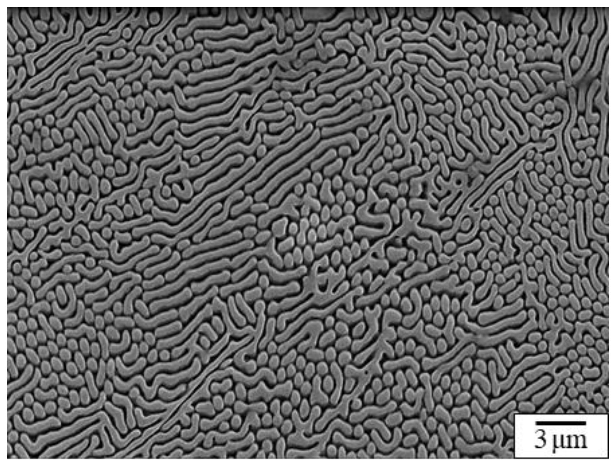
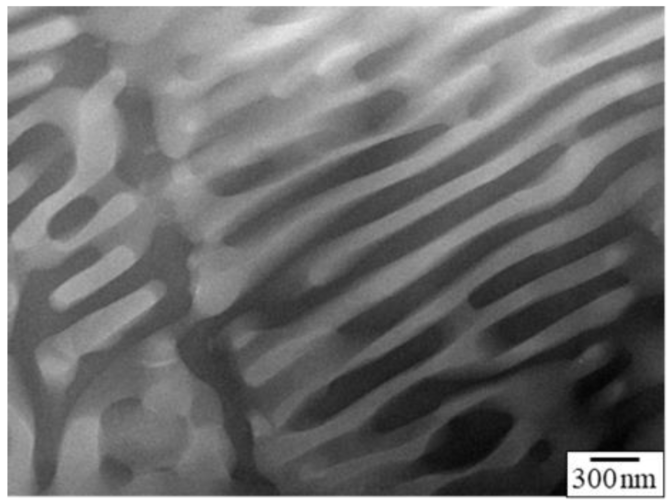
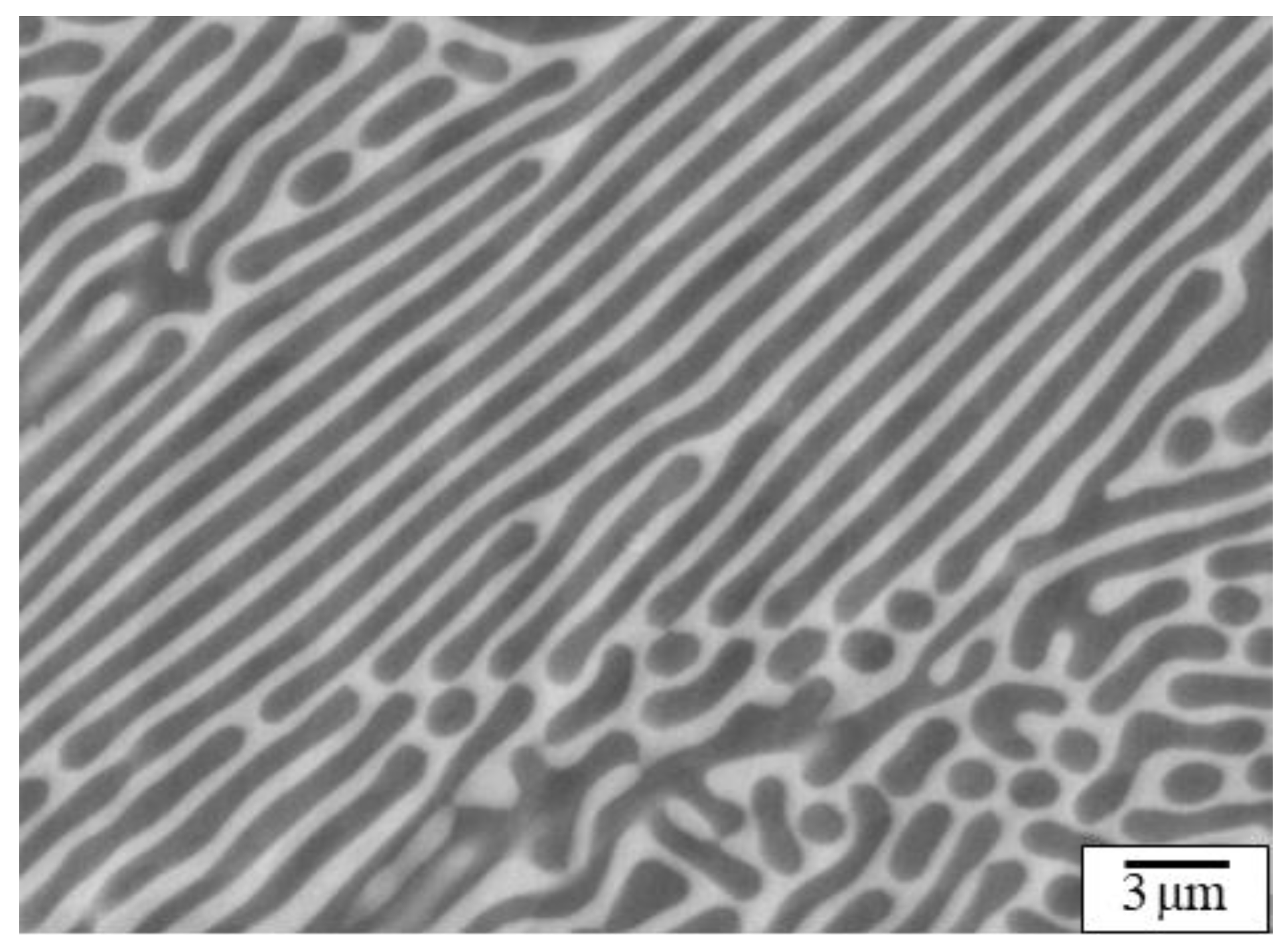
3.1. Initial Microstructure
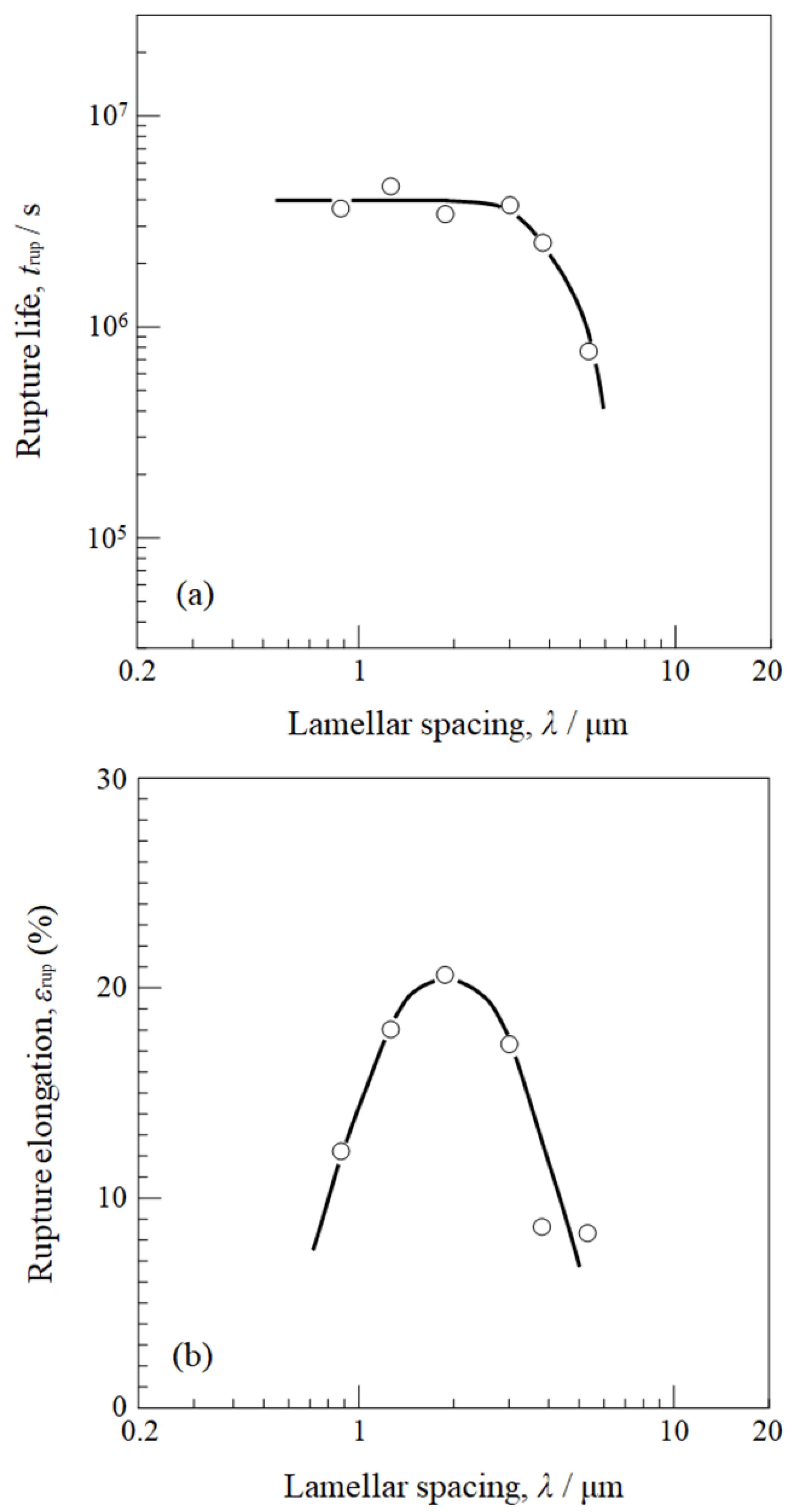
3.2. Creep Properties
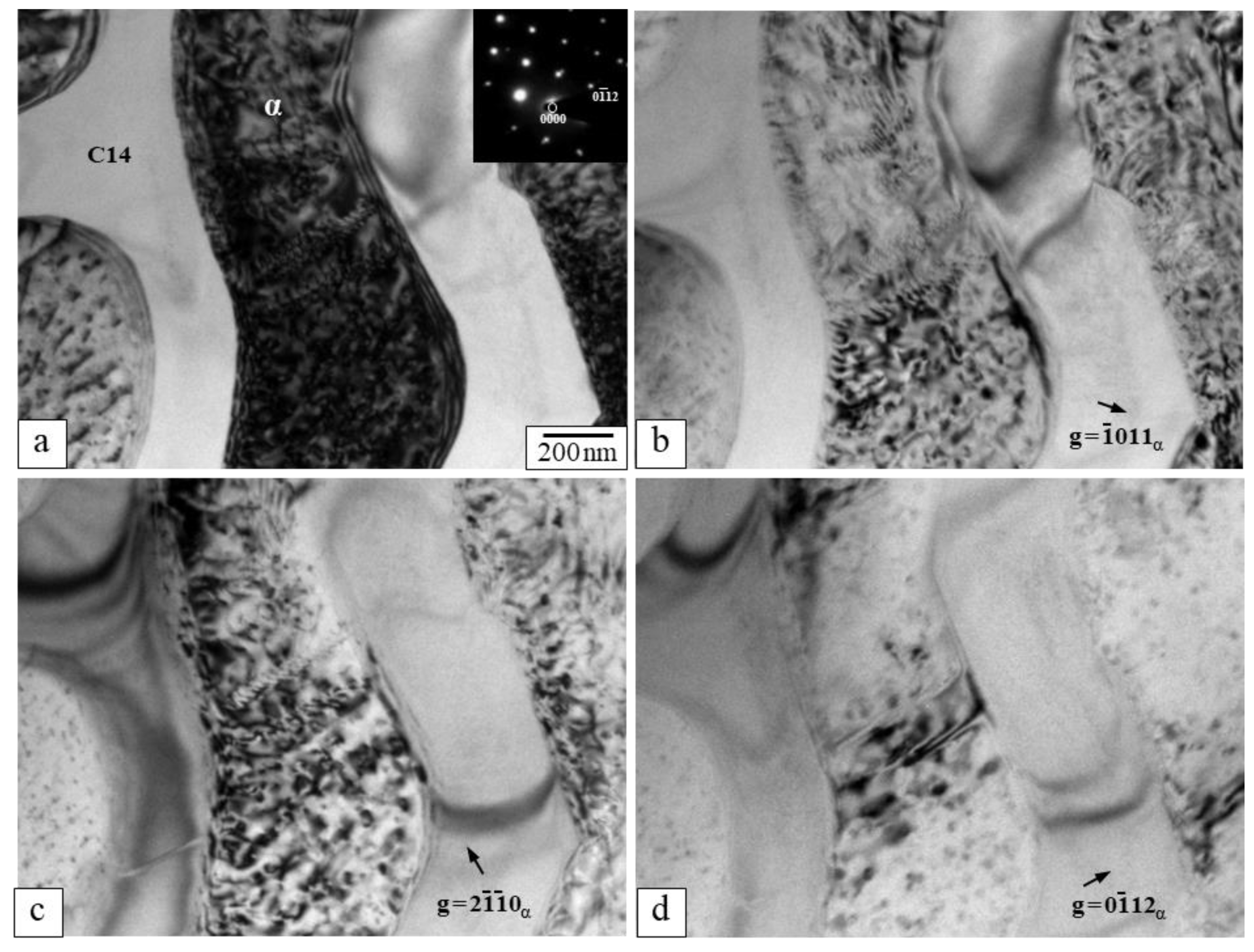
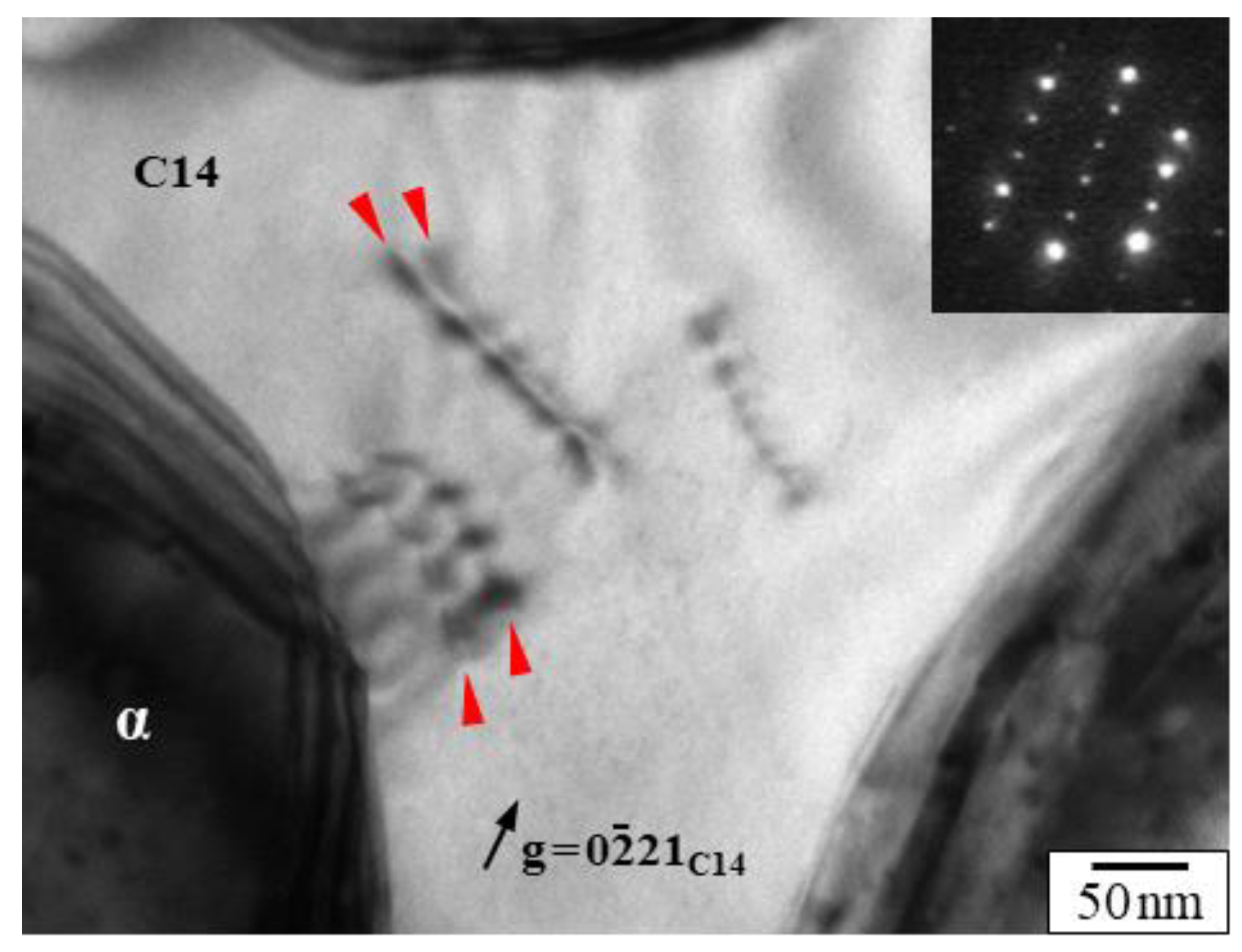
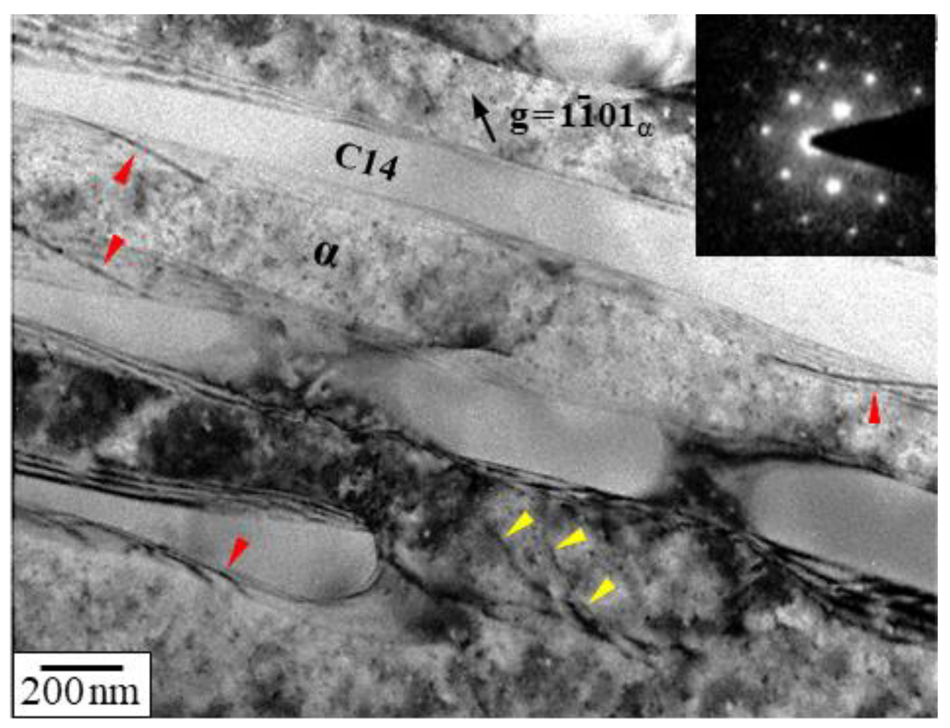
3.3. Dislocation Analysis
4. Conclusions
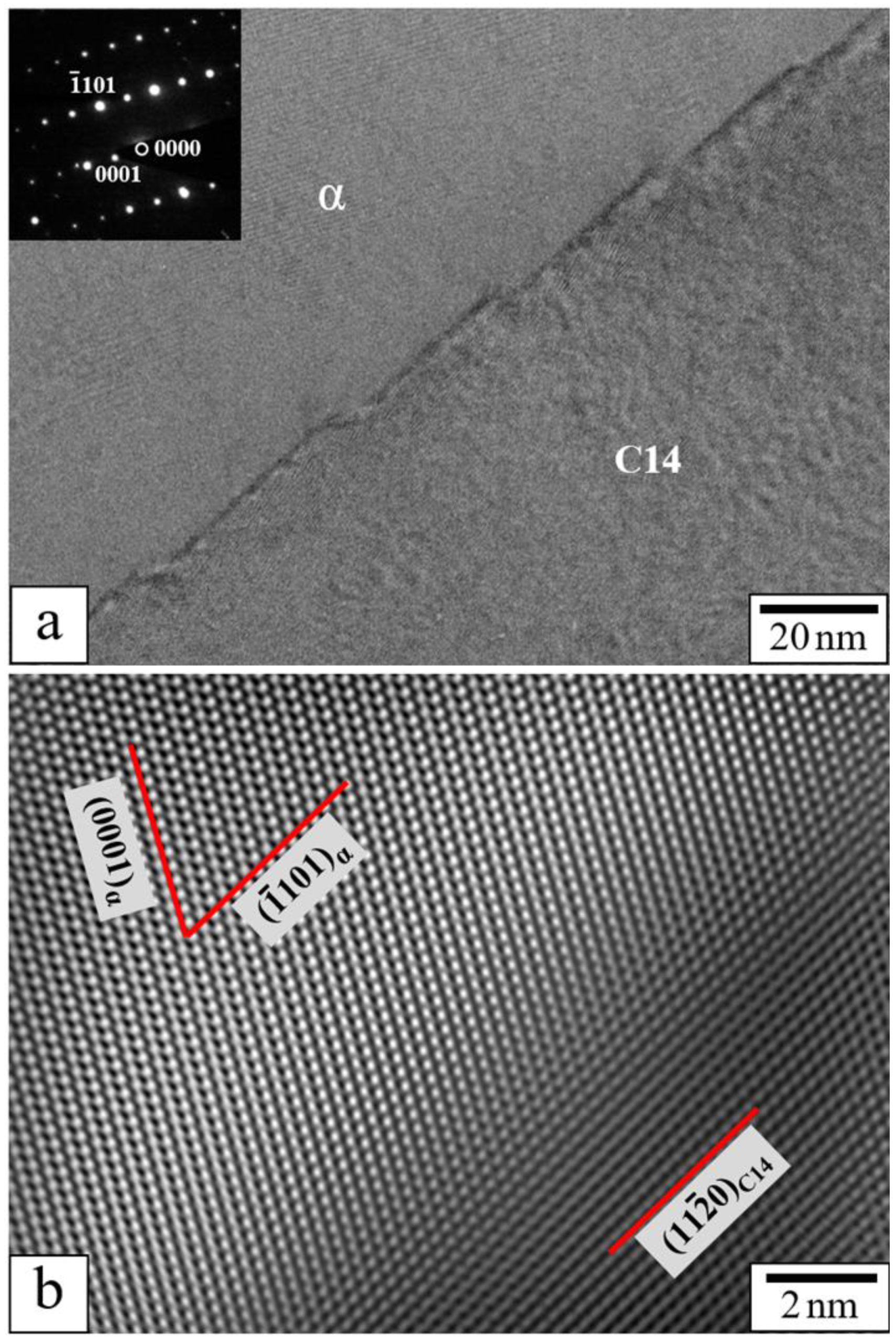
- The α/C14 interface is composed of terraces and steps, with terraces parallel to the (1101)α pyramidal plane of the α-Mg lamellae and to the (1120)C14 columnar plane of the C14–Mg2Ca lamellae.
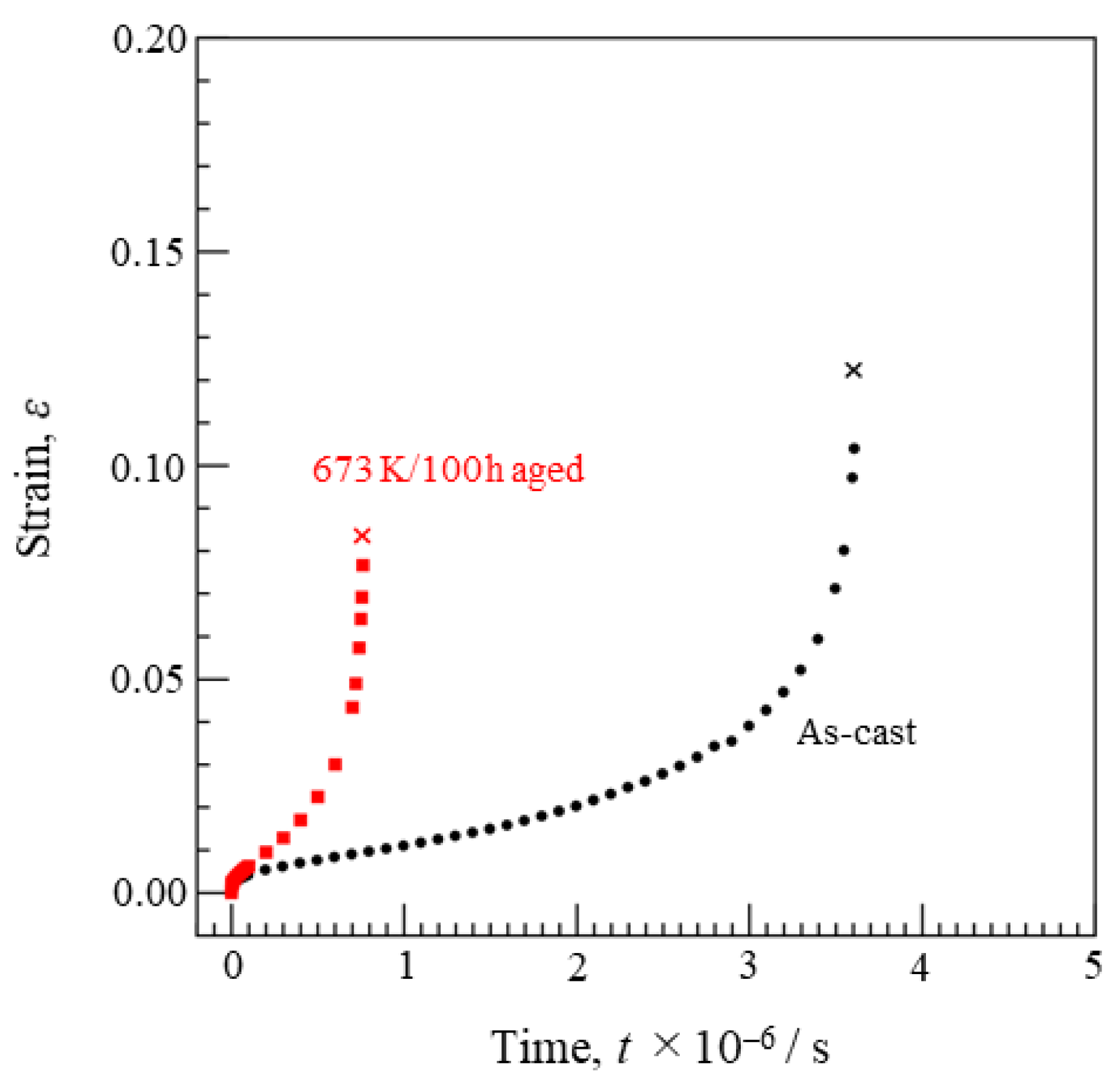
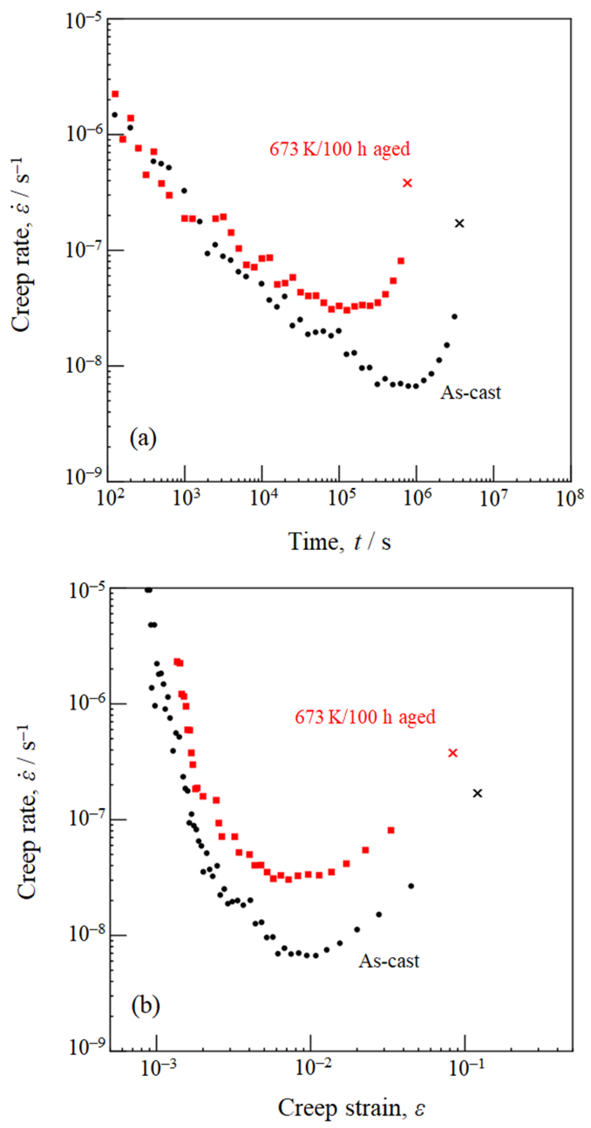
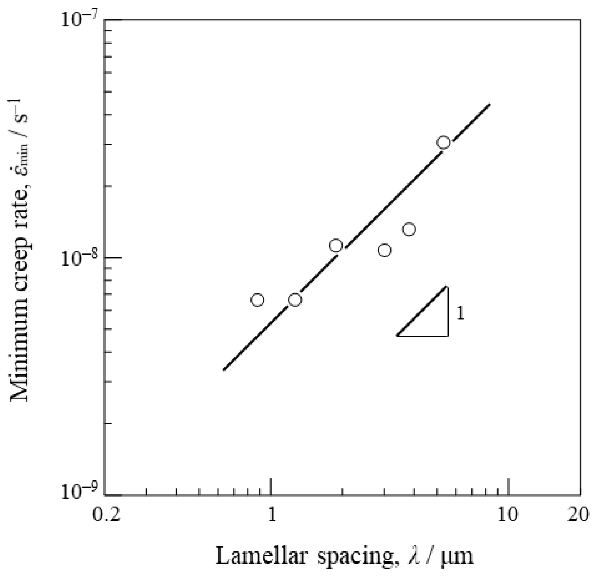
- The alloy shows three stages of creep: a normal transient creep stage, a minimum creep rate stage, and an accelerating stage. A well-defined steady state is barely evident. Since the minimum creep rate decreases continuously with decreasing lamellar spacing, the α-Mg/C14–Mg2Ca interface is considered to enhance the creep strength; that is to say, the α-Mg/C14–Mg2Ca interface acts as a creep-strengthener.
- Dislocations are mainly introduced within the soft α-Mg lamellae during creep, and most of them are <a> dislocations with identical Burgers vectors. The dislocations are not arranged, but randomly distributed at the α/C14 interface. Dislocations are rarely introduced in the hard C14–Mg2Ca lamellae, and the dissociation reaction from a perfect dislocation to two partial dislocations is detected in the C14–Mg2Ca lamellae.
Author Contributions
Funding
Data Availability Statement
Acknowledgments
Conflicts of Interest
References
- Agnew, S.R.; Nie, J.F. Preface to the viewpoint set on: The current state of magnesium alloy science and technology. Scr. Mater. 2010, 63, 671–673. [Google Scholar] [CrossRef]
- Luo, A.A. Recent magnesium alloy development for elevated temperature applications. Int. Mater. Rev. 2004, 49, 13–30. [Google Scholar] [CrossRef]
- Zhu, S.M.; Mordike, B.L.; Nie, J.F. Creep properties of a Mg–Al–Ca alloy produced by different casting technologies. Mater. Sci. Eng. A 2008, 483–484, 583–586. [Google Scholar] [CrossRef]
- Vagarali, S.S.; Langdon, T.G. Deformation mechanisms in h.c.p. metals at elevated temperatures—I. Creep behavior of magnesium. Acta Metall. 1981, 29, 1969–1982. [Google Scholar] [CrossRef]
- Shi, L.; Northwood, D.O. Strain-hardening and recovery during the creep of pure polycrystalline magnesium. Acta Metall. Mater. 1994, 42, 871–877. [Google Scholar] [CrossRef]
- Massalski, T.B. Binary Alloy Phase Diagrams, 2nd ed.; ASM International: Materials Park, OH, USA, 1990. [Google Scholar]
- Luo, A.A.; Balogh, M.P.; Powell, B.R. Creep and microstructure of magnesium–aluminum–calcium based alloys. Metall. Mater. Trans. A 2002, 33, 567–574. [Google Scholar] [CrossRef]
- Terada, Y.; Ishimatsu, N.; Sato, T. Creep parameters in a die-cast Mg–Al–Ca alloy. Mater. Trans. 2007, 48, 2329–2335. [Google Scholar] [CrossRef] [Green Version]
- Suzuki, A.; Saddock, N.D.; TerBush, J.R.; Powell, B.R.; Jones, J.W.; Pollock, T.M. Precipitation strengthening of a Mg–Al–Ca-based AXJ530 die-cast alloy. Metall. Mater. Trans. A 2008, 39, 696–702. [Google Scholar] [CrossRef]
- Nie, J.-F. Precipitation and hardening in magnesium alloys. Metall. Mater. Trans. A 2012, 43, 3891–3939. [Google Scholar] [CrossRef] [Green Version]
- Hort, N.; Huang, Y.; Kainer, K.U. Intermetallics in magnesium alloys. Adv. Eng. Mater. 2006, 8, 235–240. [Google Scholar] [CrossRef]
- Pollock, T.M. Weight loss with magnesium alloys. Science 2010, 328, 986–987. [Google Scholar] [CrossRef]
- Misra, A.; Gibala, R. Plasticity in multiphase intermetallics. Intermetallics 2000, 8, 1025–1034. [Google Scholar] [CrossRef]
- Milenkovic, S.; Palm, M. Microstructure and mechanical properties of directionally solidified Fe–Al–Nb eutectic. Intermetallics 2008, 16, 1212–1218. [Google Scholar] [CrossRef]
- Perepezko, J.H. The hotter the engine, the better. Science 2009, 326, 1068–1069. [Google Scholar] [CrossRef]
- Takata, N.; Okano, T.; Suzuki, A.; Kobashi, M. Microstructure of intermetallic-reinforced Al-based alloy composites fabricated using eutectic reactions in Al–Mg–Zn ternary system. Intermetallics 2018, 95, 48–58. [Google Scholar] [CrossRef]
- Suzuki, A.; Saddock, N.D.; Jones, J.W.; Pollock, T.M. Phase equilibria in the Mg–Al–Ca ternary system at 773 and 673 K. Metall. Mater. Trans. A 2006, 37, 975–983. [Google Scholar] [CrossRef]
- Luo, A.A.; Powell, B.R.; Sachdev, A.K. Computational phase equilibria and experimental investigation of magnesium–aluminum–calcium alloys. Intermetallics 2012, 24, 22–29. [Google Scholar] [CrossRef]
- Terada, Y.; Itoh, D.; Sato, T. Dislocation analysis of die-cast Mg–Al–Ca alloy after creep deformation. Mater. Sci. Eng. A 2009, 523, 214–219. [Google Scholar] [CrossRef]
- Terada, Y.; Murata, Y.; Sato, T. Life assessment of die-cast Mg–5Al–1.7Ca alloys under creep service conditions. Mater. Sci. Eng. A 2014, 613, 136–140. [Google Scholar] [CrossRef]
- Kashiwase, S.; Unekawa, M.; Hisazawa, H.; Terada, Y. Three-dimensional morphology of C15–Al2Ca precipitates in a Mg–Al–Ca alloy. Mater. Trans. 2019, 60, 2048–2052. [Google Scholar] [CrossRef]
- Kashiwase, S.; Unekawa, M.; Hisazawa, H.; Terada, Y. C15–Al2Ca precipitation in a Mg–Al–Ca alloy. Mater. Trans. 2020, 61, 375–380. [Google Scholar] [CrossRef]
- Suzuki, A.; Saddock, N.D.; Jones, N.D.; Pollock, T.M. Solidification paths and eutectic intermetallic phases in Mg–Al–Ca ternary alloys. Acta Mater. 2005, 53, 2823–2834. [Google Scholar] [CrossRef]
- Xu, S.W.; Oh-ishi, K.; Kamado, S.; Takahashi, H.; Homma, T. Effects of different cooling rates during two casting processes on the microstructures and mechanical properties of extruded Mg–Al–Ca–Mn alloy. Mater. Sci. Eng. A 2012, 542, 71–78. [Google Scholar] [CrossRef]
- Zubair, M.; Sandlöbes, S.; Wollenweber, M.A.; Kusche, C.F.; Hildebrandt, W.; Broeckmann, C.; Korte-Kerzel, S. On the role of Laves phases on the mechanical properties of Mg–Al–Ca alloys. Mater. Sci. Eng. A 2019, 756, 272–283. [Google Scholar] [CrossRef]
- Abe, S.; Oishi, K.; Terada, Y. Lamellar structure stability of a two-phase α-Mg/C14–Mg2Ca alloy. Mater. Trans. 2021, 62, 544–550. [Google Scholar] [CrossRef]
- Ray, K.K.; Mondal, D. The effect of interlamellar spacing on strength of pearlite in annealed eutectoid and hypoeutectoid plain carbon steels. Acta Metall. Mater. 1991, 39, 2201–2208. [Google Scholar] [CrossRef]
- Maziasz, P.J.; Liu, C.T. Development of ultrafine lamellar structures in two-phase γ-TiAl alloys. Metall. Mater. Trans. A 1998, 29, 105–117. [Google Scholar] [CrossRef]
- Baker, I.; Meng, F. Lamellar coarsening in Fe28Ni18Mn33Al21 and its influence on room temperature tensile behavior. Acta Mater. 2015, 95, 124–131. [Google Scholar] [CrossRef] [Green Version]
- Lei, Q.; Ramakrishnan, B.P.; Wang, S.; Wang, Y.; Mazumder, J.; Misra, A. Structural refinement and nanomechanical response of laser remelted Al–Al2Cu lamellar eutectic. Mater. Sci. Eng. A 2017, 706, 115–125. [Google Scholar] [CrossRef]
- Ishimatsu, N.; Terada, Y.; Sato, T.; Ohori, K. Creep characteristics of a diecast AM50 magnesium alloy. Metall. Mater. Trans. A 2006, 37, 243–248. [Google Scholar] [CrossRef]
- Terada, Y.; Enokida, T.; Sato, T. Effect of prior deformation on creep behavior of a die-cast Mg–Al–Ca alloy. Mater. Trans. 2009, 50, 2351–2354. [Google Scholar] [CrossRef]
- Sandström, R. Basic model for primary and secondary creep in copper. Acta Mater. 2012, 60, 314–322. [Google Scholar] [CrossRef]
- Li, Y.P.; Zhang, G.P.; Wang, W.; Tan, J.; Zhu, S.J. On interface strengthening ability in metallic multilayers. Scr. Mater. 2007, 57, 117–120. [Google Scholar] [CrossRef]
- Cadek, J. Creep in Metallic Materials; Elsevier: Amsterdam, The Netherlands, 1988. [Google Scholar]
- Kassner, M.E.; Perez-Prado, M.T. Fundamentals of Creep in Metals and Alloys; Elsevier: Amsterdam, The Netherlands, 2004. [Google Scholar]
- Oishi, K.; Araki, S.; Terada, Y. Effect of lamellar spacing on creep strength of α-Mg/C14–Mg2Ca eutectic alloy. Mater. Trans. 2021, 62, 1414–1419. [Google Scholar] [CrossRef]
- Guénolé, J.; Zubair, M.; Roy, S.; Xie, Z.; Lipińska-Chwałek, M.; Sandlöbes-Haut, S.; Korte-Kerzel, S. Exploring the transfer of plasticity across Laves phase interfaces in a dual phase magnesium alloy. Mater. Des. 2021, 202, 109572. [Google Scholar] [CrossRef]
- Zehnder, C.; Czerwinski, K.; Molodov, K.D.; Sandlöbes-Haut, S.; Gibson, J.S.K.-L.; Korte-Kerzel, S. Plastic deformation of single crystalline C14 Mg2Ca Laves phase at room temperature. Mater. Sci. Eng. A 2019, 759, 754–761. [Google Scholar] [CrossRef]


| Specimen | λ (μm) | trup (s) | εrup (%) | |
|---|---|---|---|---|
| As-cast | 0.9 | 6.6 × 10⁻⁹ | 3.6 × 10⁶ (1006 h) | 12.2 |
| 673 K/3 h aged | 1.3 | 6.6 × 10⁻⁹ | 4.6 × 10⁶ (1283 h) | 18.0 |
| 673 K/10 h aged | 1.9 | 1.1 × 10⁻⁸ | 3.4 × 10⁶ (947 h) | 20.6 |
| 673 K/30 h aged | 3.0 | 1.1 × 10⁻⁸ | 3.8 × 10⁶ (1042 h) | 17.3 |
| 673 K/50 h aged | 3.4 | 1.3 × 10⁻⁸ | 2.5 × 10⁶ (692 h) | 8.5 |
| 673 K/100 h aged | 5.3 | 3.0 × 10⁻⁸ | 7.6 × 10⁵ (212 h) | 8.3 |
| Mode | b | g = 1011 | 2110 | 0112 |
|---|---|---|---|---|
| <a> | 1/3 [1120] | −1 | 1 | −1 |
| 1/3 [1210] | 0 | 1 | 1 | |
| 1/3 [2110] | 1 | −2 | 0 | |
| <a+c> | 1/3 [1123] | 0 | 1 | 1 |
| 1/3 [1213] | 1 | 1 | 3 | |
| 1/3 [2113] | 2 | −2 | 2 | |
| 1/3 [1123] | −2 | 1 | −3 | |
| 1/3 [1213] | −1 | 1 | −1 | |
| 1/3 [2113] | 0 | −2 | −2 | |
| <c> | [0001] | 1 | 0 | 2 |
Publisher’s Note: MDPI stays neutral with regard to jurisdictional claims in published maps and institutional affiliations. |
© 2021 by the authors. Licensee MDPI, Basel, Switzerland. This article is an open access article distributed under the terms and conditions of the Creative Commons Attribution (CC BY) license (https://creativecommons.org/licenses/by/4.0/).
Share and Cite
Araki, S.; Oishi, K.; Terada, Y. Interface Strengthening of α-Mg/C14–Mg2Ca Eutectic Alloy. Metals 2021, 11, 1913. https://doi.org/10.3390/met11121913
Araki S, Oishi K, Terada Y. Interface Strengthening of α-Mg/C14–Mg2Ca Eutectic Alloy. Metals. 2021; 11(12):1913. https://doi.org/10.3390/met11121913
Chicago/Turabian StyleAraki, Satoshi, Koji Oishi, and Yoshihiro Terada. 2021. "Interface Strengthening of α-Mg/C14–Mg2Ca Eutectic Alloy" Metals 11, no. 12: 1913. https://doi.org/10.3390/met11121913
APA StyleAraki, S., Oishi, K., & Terada, Y. (2021). Interface Strengthening of α-Mg/C14–Mg2Ca Eutectic Alloy. Metals, 11(12), 1913. https://doi.org/10.3390/met11121913