Article

Optimization of the Microwave-Assisted Carbothermical Reduction Process for Metals from Electric Arc Furnace Dust with Biochar

1
Physics Faculty, Chelyabinsk State University, 129 Br. Kashirinykh Str., 454021 Chelyabinsk, Russia
2
Institute of Advanced Data Transfer Systems, ITMO University, Kronverksky Pr. 49, Bldg. A, 197101 St. Petersburg, Russia
3
School of Minerals Processing and Bioengineering, Central South University, Changsha 410083, China
*
Author to whom correspondence should be addressed.
Metals 2021, 11(11), 1765; https://doi.org/10.3390/met11111765
Submission received: 31 August 2021 / Revised: 26 October 2021 / Accepted: 29 October 2021 / Published: 3 November 2021
(This article belongs to the Special Issue Advances in Powder Metallurgy)

Abstract

:
The main purpose of this work was to extract valuable metals from EAF dust with the addition of biochar, using microwaves to control and optimize the carbothermical reduction process. To achieve better microwave penetration and the most homogeneous electromagnetic heat source distribution possible in a sample, the content of EAF dust and biochar in centimeter-size spherical particles prepared by the pelletization process was considered to be radially heterogeneous. The content of EAF dust was determined experimentally and the effective permittivity, permeability, and thermal conductivity of the EAF dust as well as biochar–EAF powder mixture were determined using effective medium approximation. The microwave heating of a multilayered pellet of biochar-containing EAF dust was simulated and investigated. The influence of the distribution of the components within the pellet on the effectiveness of the microwave heating was investigated, as was the influence of the biochar conductivity. The interaction of the pellet with both plane waves in free space and with H10 mode waves in a single-mode waveguide was considered. The most optimal distribution of EAF dust and biochar within the pellet for the reduction process was determined.

1. Introduction

EAF dust is a metallurgical waste produced in the EAF steelmaking process. In general, the output of EAF dust is about 1–2% of the EAF charge [1]. Biochar or hydrolysis lignin is a carbon-containing waste produced by the pulp and paper industry [2]. The relevance of the problem is due to the need to use the accumulated EAF dust and biochar. It is equally important to learn how to use these wastes as a secondary raw material. It is known [3,4] that it is possible to perform the microwave-intensified reduction of Zn, Fe, and Pb from briquettes consisting of carbon and EAF dust under a C/Fe mass ratio of 0.25.
The most commonly used method for EAF dust reduction is the Waelz process [5]. The main disadvantages of this method are its high consumption of coke and coal as reducing agents and its low metallization rate of near 75%. Moreover, to ensure economic benefits, a zinc content of the dust of over 16% [6,7] is required. The stable spinel structure of franklinite (ZnFe2O4) means that a high energy input is required to decompose it in the reduction process [8]. Therefore, in recent years much attention has been given to the use of microwave heating for the intensification of the reduction process of EAF dust. Microwave heating shows a high thermal efficiency due to the peculiarities of volumetric and selective heating [9]. In paper [10], it was reported that the reduction of metal oxides in dust through microwave irradiation can be achieved in 20 minutes with a high percentage of dezincification (92.79%) when using blast-furnace slag as a reducing agent.
In [11,12], a method for intensifying the reduction of iron ore by reducing core–shell iron ore–biochar composite pellets under microwave irradiation was proposed. This method took advantage of the microwave-induced directional migration of different elements. The results showed that microwaves played an important role in intensifying the self-reduction of core–shell composite pellets.
Biochar was used as the reducing agent in this process mainly because of its high chemical reactivity and low impurity content. In the works [3,13], the microwave-assisted reduction of the EAF dust–biochar composite system was investigated through thermodynamic and experimental analyses, focusing on the transition of the microwave heating mechanism. Three stages of the microwave heating mechanisms were determined according to the dynamics of the chemical reactions taking place during the microwave heating process. Paper [3] focuses on the subsequent extraction processes of multiple valuable components from samples treated by microwaves. However, in these works, cylindrical briquettes with a homogeneous distribution of components were used, which is not optimal from an electrodynamics point of view. The aim of this paper is to optimize the initial stage of the process by analyzing the electrodynamic aspects of various compositions and structures of green samples.
The main idea of this work was to use spherical pellets instead of briquettes because the pelletization process is more convenient than briquette formation in industry applications. Prior to this [14], this approach was already successfully applied for the reduction of a mixture of green iron ores as a preprocessing technology in the iron-making industry. However, in that work only homogeneous spherical pellets were considered.
This study was devoted to the investigation of the influence of the radial distribution of EAF dust in pellets on the microwave heating rate to achieve more effective microwave heating by means of surface impedance matching and a controlled reduction process throughout the pellet volume. To simulate the interaction of the microwave radiation with heterogeneous pellets, the effective permittivity and permeability were calculated using the effective medium approach.

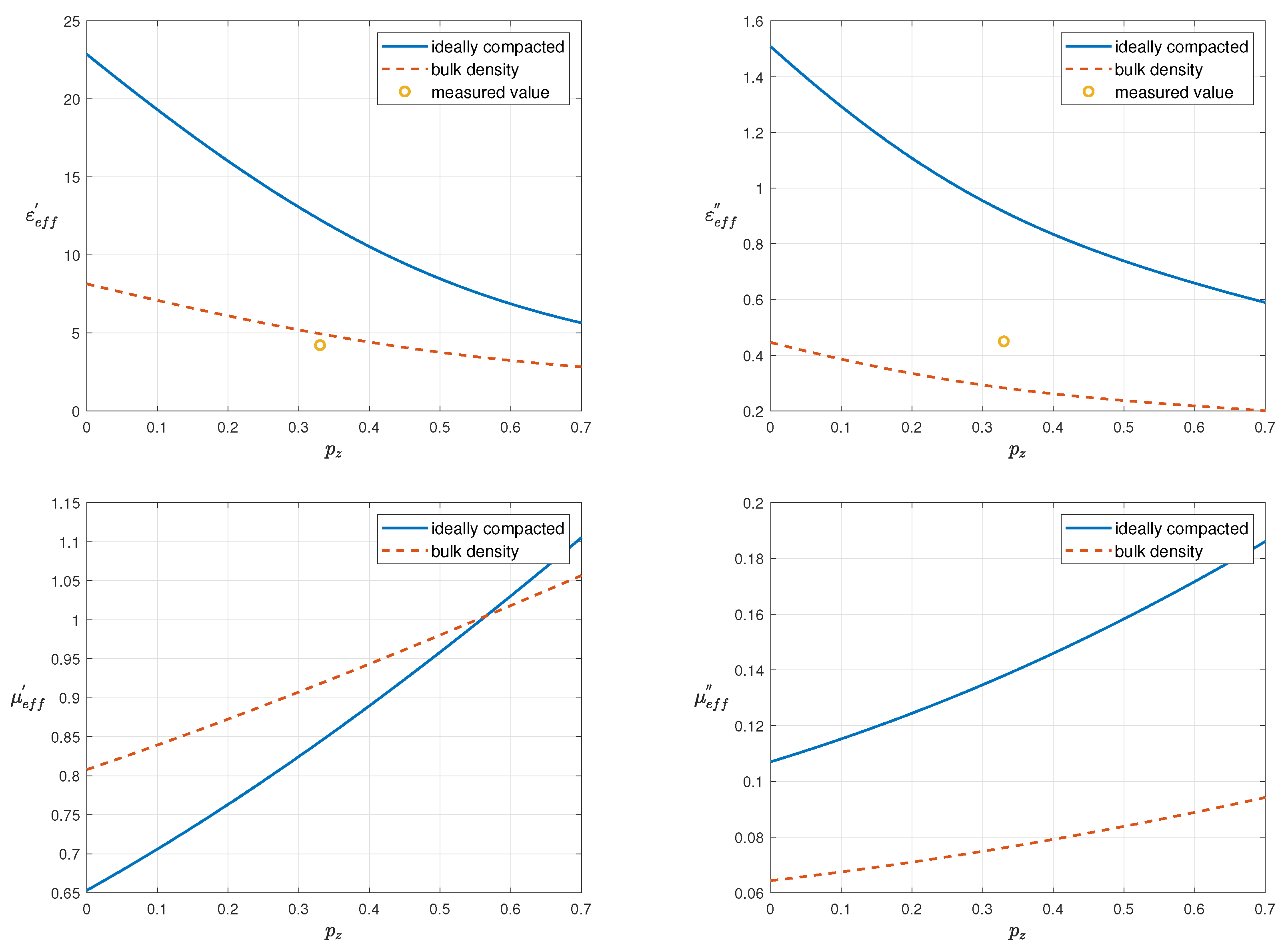
2. Effective Permittivity and Permeability of EAF Dust

First, it is required to calculate the possible effective permittivity and permeability of EAF dust itself. In Table 1, it is possible to see the content of EAF dust and all the properties required to calculate the effective permittivity and permeability— ε is the real part of permittivity (relative dielectric constant), σ is the electric conductivity, μ is the real part of magnetic permeability, and μ is the imaginary part of magnetic permeability.
According to work [20], in the process of the blowing of iron-bearing melt with oxygen, dispersed particles in the flue gases have a layered composition, with Fe2O3 on the surface and Fe3O4 underneath it. Let us assume that zinc-containing particles have the same core–shell structure, with ZnFe2O4 in the core and ZnO in the shell of particles. Eventually, for model of EAF powder, a mixture of three types of particles can be seen: core–shell iron-containing spherical particles (Fe3O4-Fe2O3); core–shell zinc-containing spherical particles (ZnFe2O4-ZnO); and simple spherical particles of CaMgSiO4, which is used as the main filler of the mixture of powders. The content of SiO2 is negligible. A schematic illustration of the model of such core–shell particles is shown in Figure 1.
For the calculation of the effective permittivity and permeability of such a model, the effective medium approach and enhanced Bruggeman equation for two types of core–shell particles in a filler medium was used (1) [21] According to effective medium theory, this equation can be obtained with the assumption that each core–shell particle is in some effective medium with an effective permittivity due to the influence of all the other particles. In this case, and assuming that each particle is small enough for us to write the solution of Maxwell’s equations for it in stationary approximation, the following equation is obtained:
( 1 p z ξ z p f ξ f ) ε c ε e f f ε c + 2 ε e f f + + p z ξ z ε z s h 3 ε z + ( ξ z 1 ) ( ε z + 2 ε z s h ) ε e f f 3 ε z s h + ( ξ z 1 ) ( ε z + 2 ε z s h ) 2 α z ε e f f + β z ε z s h + + p f ξ f ε f s h [ 3 ε f + ( ξ f 1 ) ( ε f + 2 ε f s h ) ] ε e f f [ 3 ε f s h + ( ξ f 1 ) ( ε f + 2 ε f s h ) ] 2 α f ε e f f + β f ε f s h p z ξ z 9 2 ε z s h ( ε z ε z s h ) ln ( 1 + l z ) 2 α z ε e f f + β z ε z s h p f ξ f 9 2 ε f s h ( ε f ε f s h ) ln ( 1 + l f ) 2 α f ε e f f + β f ε f s h = 0
Here, the geometrical parameters of the core–shell spherical particles are expressed as follows: ξ z , f = ( R 2 z , 2 f / R 1 z , 1 f ) 3 = ( 1 + l z , f ) 3 , l z , f = ( R 2 z , 2 f R 1 z , 1 f ) / R 1 z , 1 f , α z , f = ( ξ z , f 1 ) ε z , f + 2 ( ξ z , f + 1 ) ε z s h , f s h , β z , f = ( 2 + ξ z , f ) ε z , f + 2 ( ξ z , f 1 ) ε z s h , f s h , and p is the volume fraction of the corresponding component in a mixture. Letters z , z s h , f , f s h , c mean zinc-containing particles of the core and shell, iron-containing particles of the core and shell, and CaMgSiO4 filler particles. R 2 and R 1 are the radius of the particle with the shell and the radius of the core of the particle, respectively.
In a generalized form for N types of core–shell spherical particles, Equation (1) looks like (2):
( 1 i = 1 N p i ξ i ) ( ε c ε e f f ) i = 1 N ( 2 α i ε e f f + β i ε i s h e l l ) + + ( ε c 2 ε e f f ) i = 1 N p i ξ i ( ξ i 1 ) ( ε i + 2 ε i s h e l l ) ( ε i s h e l l ε e f f ) + + 3 ε i s h e l l ( ε i ε i s h e l l ) × × j = 1 , j i N ( 2 α j ε e f f + β j ε i s h e l l ) ( ε c 2 ε e f f ) i = 1 N 9 2 p i ξ i ε i s h e l l ( ε i ε i s h e l l ) ln ( 1 + l i ) × × j = 1 , j i N ( 2 α j ε e f f + β j ε i s h e l l ) = 0
Taking into account (see Table 1) the fact that both the volume fraction ratios of Fe3O4 to Fe2O3 and ZnFe2O4 to ZnO in EAF dust are almost the same and equal to 2:1, l z , f = 3 2 3 1 . In addition, in [1], it is observed that the dust had two main size fractions, namely a very fine-grained portion (0.1–1 μm) and a coarser portion (1–100 μm). According to this, let us consider that on average the radius of the ZnFe2O4 core of the zinc-containing particles is 100 nm and the radius of the Fe3O4 core of the iron-containing particles is 25 μm [3,4,20,22]. However, it can be seen that only the ratio of the thickness of the shell to the radius of the core is used in Equation (1), and the absolute values of radii of particles are given here only to estimate this ratio. Finally, the content of CaMgSiO4 particles is fixed and equal to 30% [3,23].
The effective values of the permittivity were measured using the method of the partial filling of the resonator [24]. The sample was poured into a quartz capillary and placed in a maximum electric or magnetic field, respectively Figure 2.
The real values of permittivity were determined from the shift in the resonance frequency. The change in the Q-factor of the absorption peak corresponds to the imaginary values of permittivity. During the filling of the capillary, the density of the samples changed. This was measured using standard hydrostatic weighing and took it into account through comparison with the theoretical values. Since our EAF dust is composed of 33% zinc-containing particles (Table 1), Figure 3 shows the measured values only for this volume fraction. Nevertheless, the measured value is in good agreement with the theoretical one. In further calculations, the effective permittivity and permeability of the ideally compacted EAF dust with a composition from (Table 1) were used. According to Figure 3, these values are ε e a f = 12.2613 + 0.9156 i and μ e a f = 0.8438 + 0.1379 i , respectively.

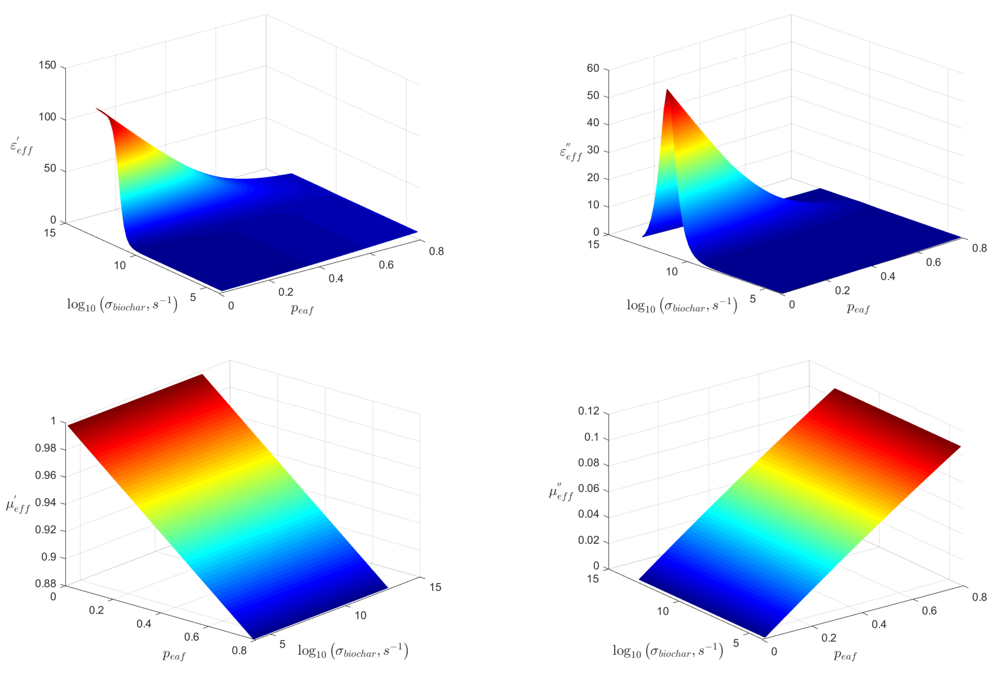
3. Effective Permittivity and Permeability of Biochar with EAF Dust Mixture

The same Equation (1) can be used to calculate the effective permittivity and permeability of a binary mixture of EAF dust particles and biochar particles both covered by a shell of bentonite binder. This model for biochar-containing mixtures bound by bentonite was approved in paper [25], where it was shown that it is more appropriate to use a core–shell model of particles covered by binder, especially in the cases where the particles are conductive. However, in the current work, the second component of the mixture is EAF dust particles with the effective permittivity and permeability calculated in the previous section. The dependencies of the effective permittivity and permeability of EAF dust–biochar–bentonite binder powder mixture on the volume fraction of EAF dust and biochar conductivity are shown in Figure 4.

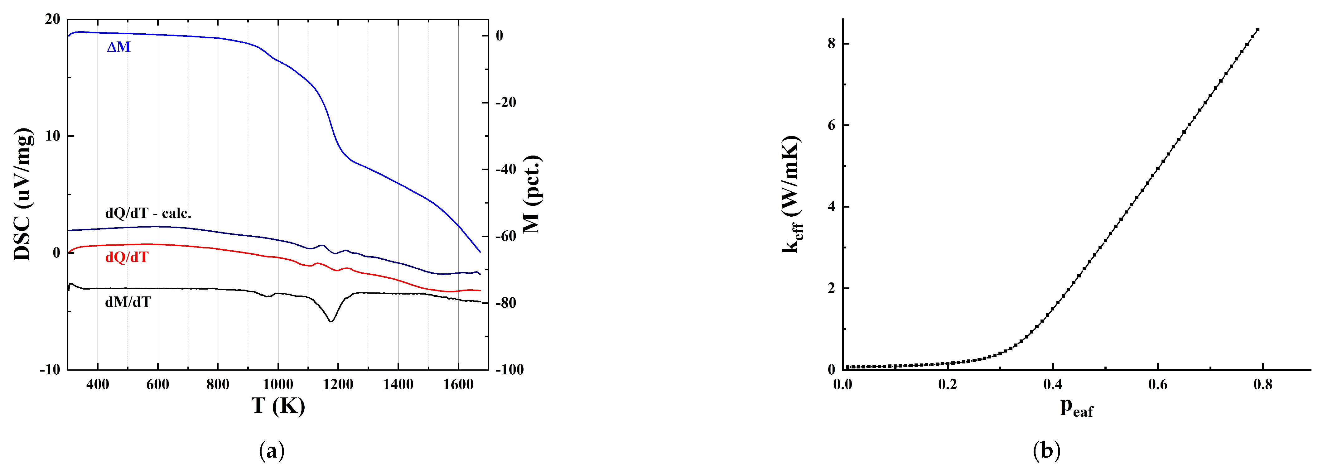
4. Effective Thermal Conductivity

In addition to the effective permittivity and permeability of the EAF dust and biochar powder mixture, the effective thermal conductivity must be calculated as well to solve the heat transfer equation. Fortunately, according to papers [26,27], it is possible to use the Bruggeman equation again but this time in a simplified form for a mixture of N spherical particles (3):
i = 1 N p i κ i κ e f f κ i + 2 κ e f f = 0
You can see the solution of Equation (3) for the thermal conductivities of the pellet compound components from papers [28,29,30,31,32,33,34] in Figure 5b.
Previous studies [35], as well as data from differential scanning calorimetry (Figure 5a), indicate that the composition of the mixture changes from a temperature of at least 800 K. Thus, the porosity of a material is determined based on chemical reactions. Since the particles of the mixture are weakly crystalline and small in size, the total thermal resistance will be determined by the thermal conductivity of the biochar and the gas in the pores. Changes in the volume fraction of biochar and the formation of process gases mixture during the main chemical reactions (4)–(8) will have a decisive influence on the effective values of thermal conductivity. The effect of radiation heat transfer in pores up to 1000 K can also be neglected.
6 Z n F e 2 O 4 + C 921 K Z n O + 4 F e 3 O 4 + C O 2
C + C O 2 978 K 2 C O
F e 3 O 4 + 4 C 981 K 3 F e + 4 C O
F e O + C 992 K F e + C O
Z n O + C 1229 K Z n + C O

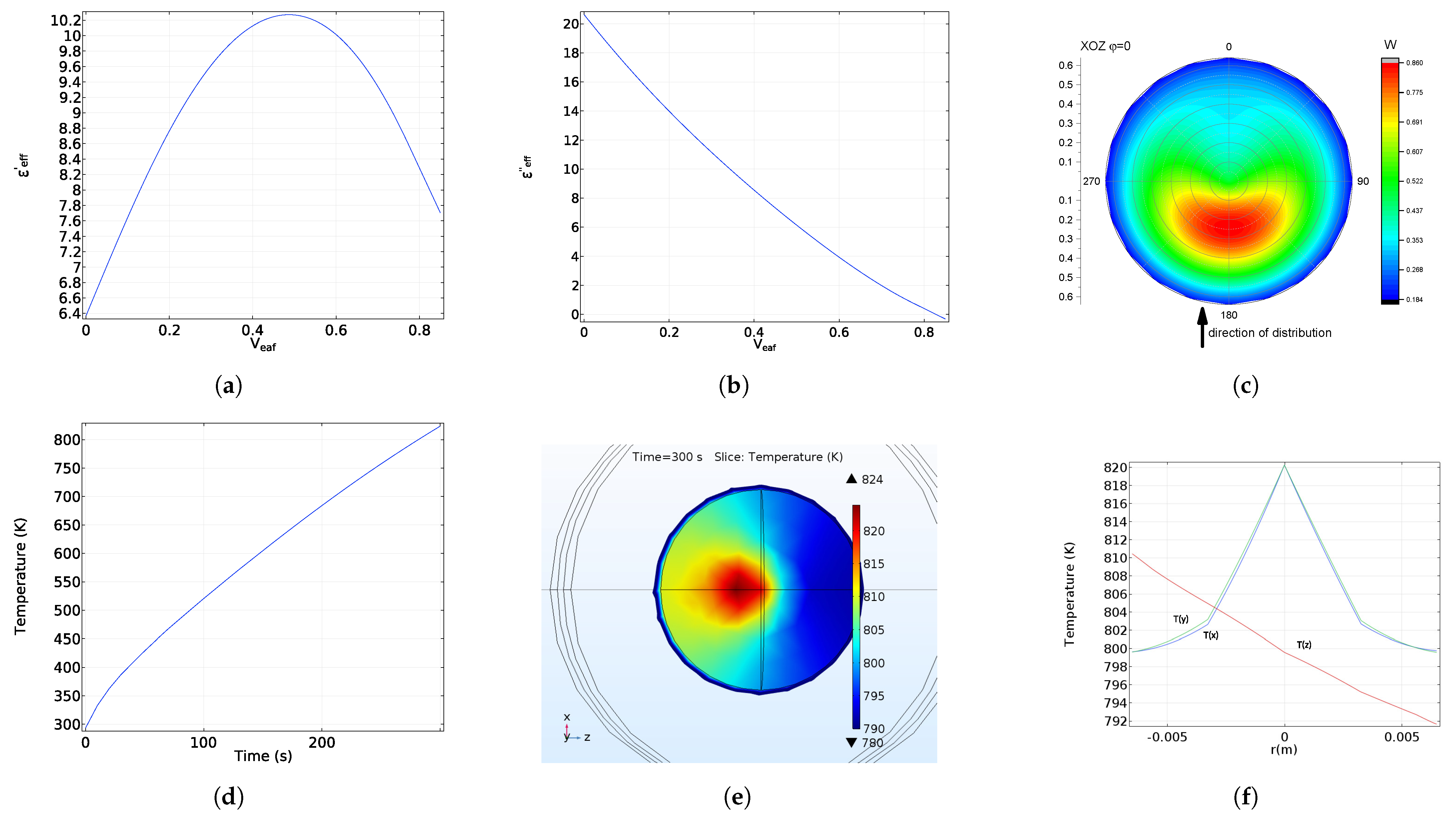
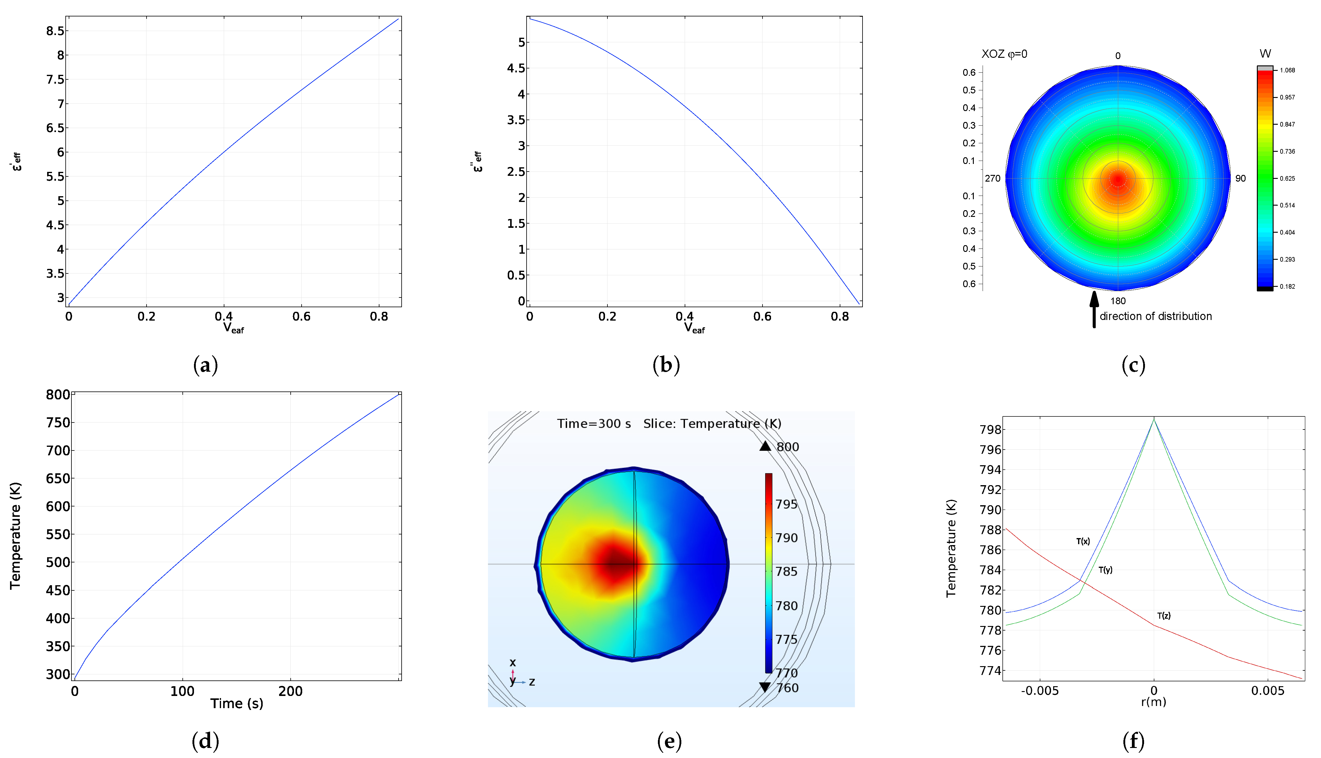
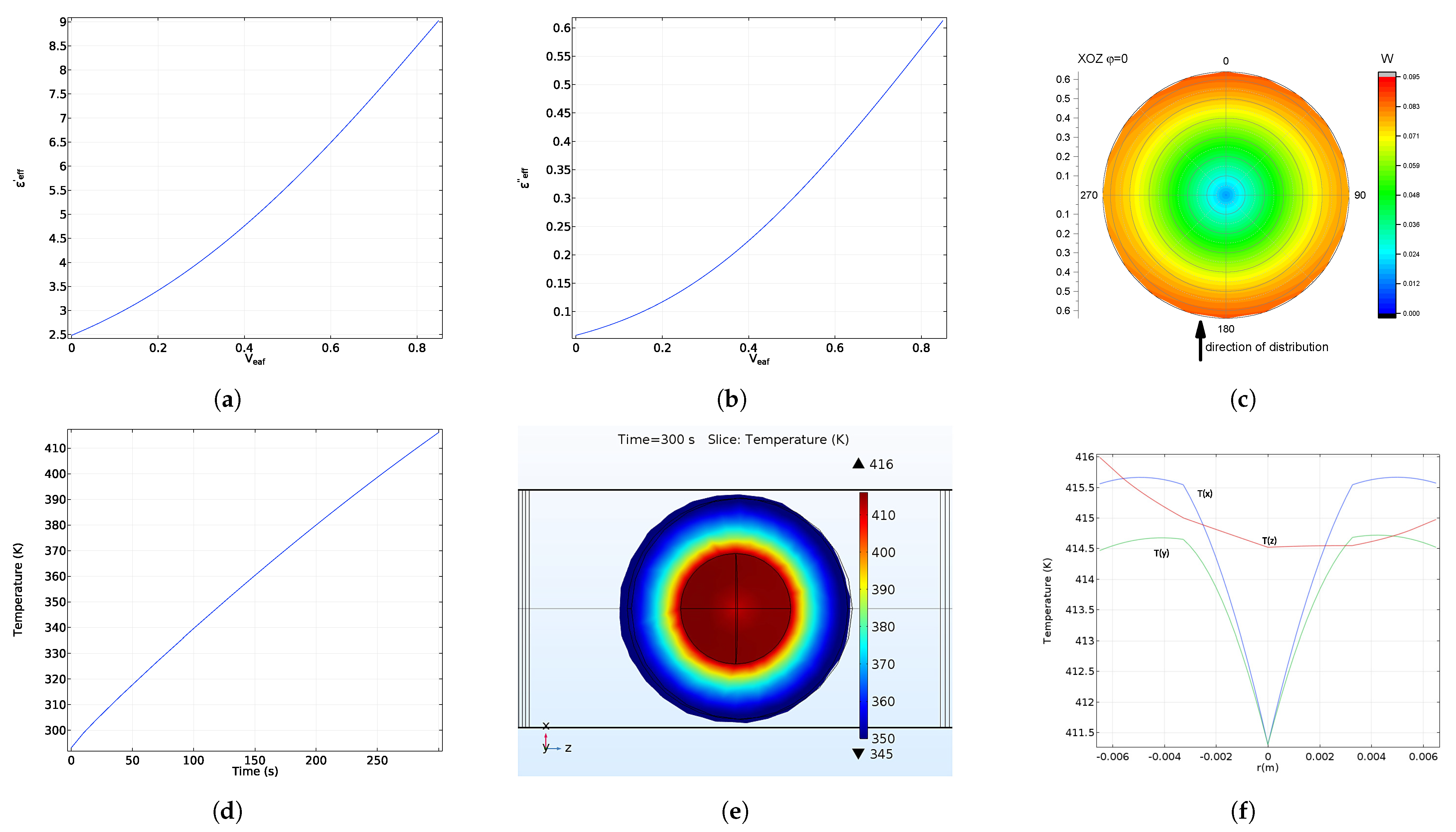
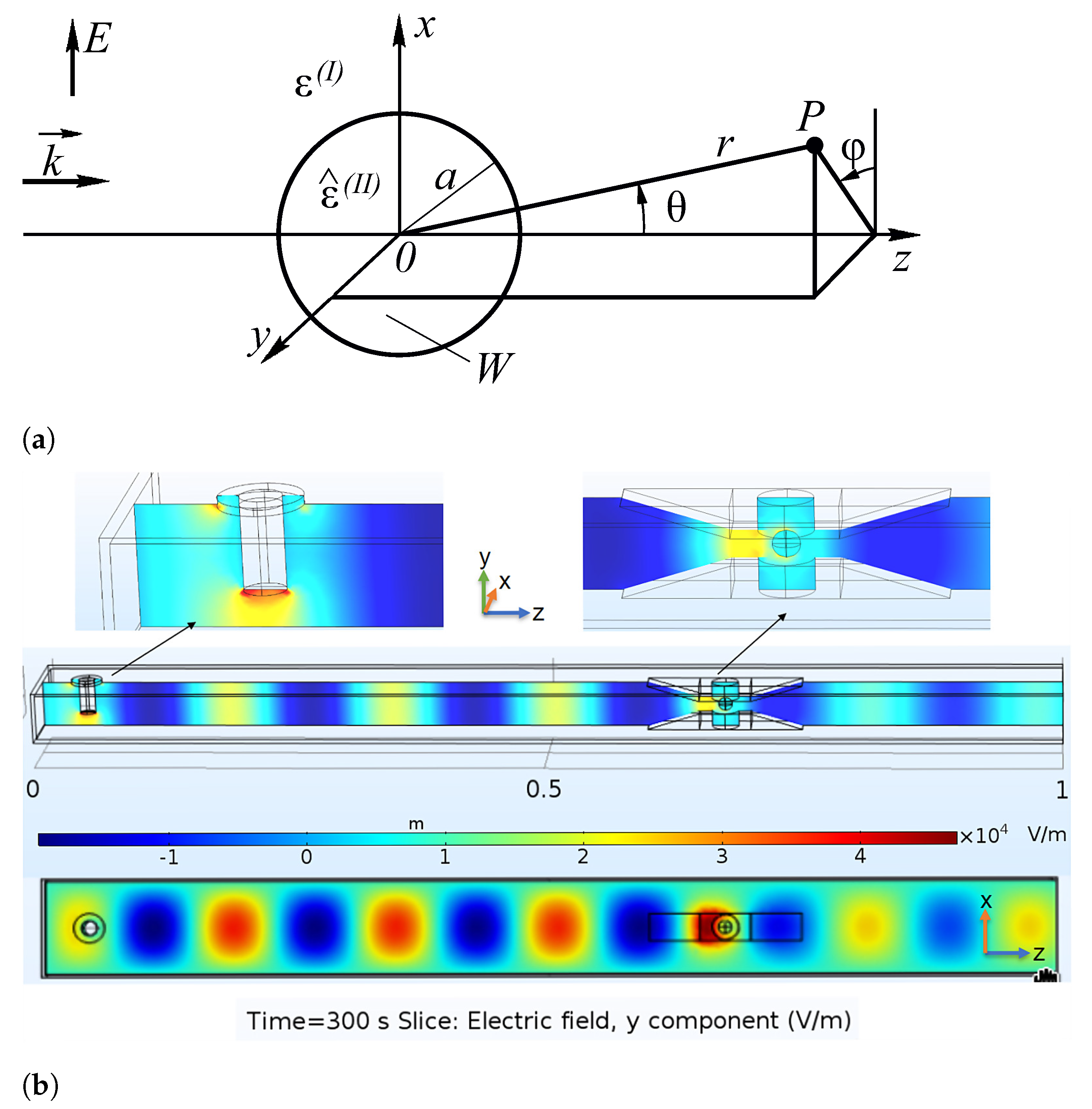
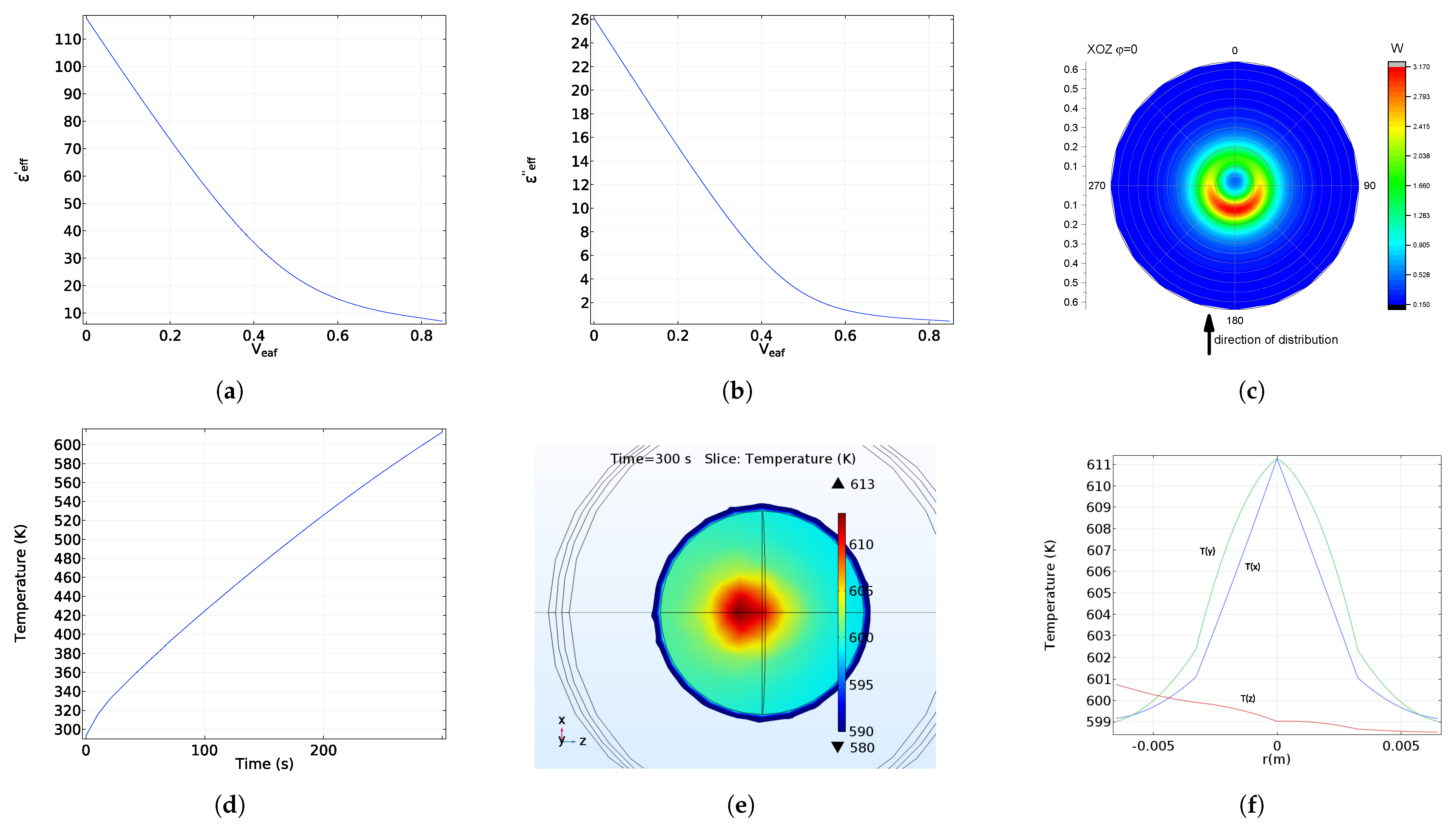
5. Electromagnetic Field and Temperature Distribution

Both analytical calculations and the finite element method simulation of Maxwell’s Equation (9) were used to obtain the electromagnetic field and temperature distribution within the single-mode rectangular waveguide as well as the pellet. The analytical solution was found by Maple in a spherical coordinate system for a plane wave falling on a spherical particle (Figure 6a). It was used to obtain the distribution of electromagnetic fields and heat sources in the pellet (10):
× μ 1 ( E ) + ( j ω σ ω 2 ε ) E = 0
W = ε | E | 2 + μ | H | 2
ρ C p T t λ T · ( λ ( T ) T ) = W
Here, C p = 1050 is the heat capacity at a constant pressure in the pellet; ρ = 2200 rg/m3 is the density; and λ is the effective thermal conductivity, which depends on the volume fraction of EAF dust, as shown in Figure 5.
The finite element method was used to simulate the microwave heating of one pellet in a single-mode rectangular waveguide by solving a coupled problem of Maxwell’s (9) equations and the heat transfer Equation (11) (Figure 6b). In this picture on the left-hand side, it is possible to see the coaxial microwave input with a frequency of 2.45 GHz. Near the right sight of the waveguide, it is possible to see the spherical sample. This was prepared by the pelletization process from green powders of EAF dust and biochar. It was built in such a way that the volume fraction of EAF dust increases linearly from the core to the surface of the particle. This can be achieved easily by the continuous changing of the composition of the pelletized mixture during the pelletization process. The radius of the spherical sample was 0.65 cm. In addition, H-type waveguide inserts were used to intensify the electric field near the sample to achieve the better heating of one spherical pellet.
Previously, in [11], it was experimentally shown for iron ore-biochar pellets that radially heterogeneous core-shell pellets show better metallization degree under microwave irradiation than homogeneous. That indirectly indicates a more efficient microwave heating of radially heterogeneous pellets. Therefore, below it was theoretically investigated which specific conditions for the inhomogeneity of the pellet from EAF dust and biochar should be met to obtain the most efficient microwave heating and impedance matching.
The distributions of the electromagnetic fields (Figure 6b, Figure 7c, Figure 8c, Figure 9c and Figure 10c) and temperatures in the pellet, as well as the temperature curves, were calculated using the finite element method (Figure 7, Figure 8, Figure 9 and Figure 10). “To gain the effective values for permittivity and permeability from Figure 1”. A set of numerical simulations with various dependency slices of the effective values for permittivity and permeability from Figure 2 were carried out to find the optimal for microwave heating distribution of EAF dust in the pellet and the conductivity of biochar.
In Figure 7, Figure 8, Figure 9 and Figure 10 all possible behaviors of real and imaginary parts of the effective permittivity depending on the radius within the pellet based in Figure 4 were investigated. Thus, in Figure 7 it is possible to see the case where both the real and imaginary parts of the permittivity decrease in the volume fraction of EAF dust, which means that they decrease in radius within the pellet. Taking this into account it was assumed that the volume fraction of EAF dust increases linearly from the core to the surface of pellet. The same way, in Figure 8 the real part of permittivity reached its maximum value at some radii, while the imaginary part of the permittivity decreased in radius within the pellet. In Figure 9, it can be seen the case where the real part increases while the imaginary part decreases. Finally, in Figure 10 is demonstrated the opposite result in that shown in Figure 7: both parts of permittivity increase simultaneously in radius within the pellet.

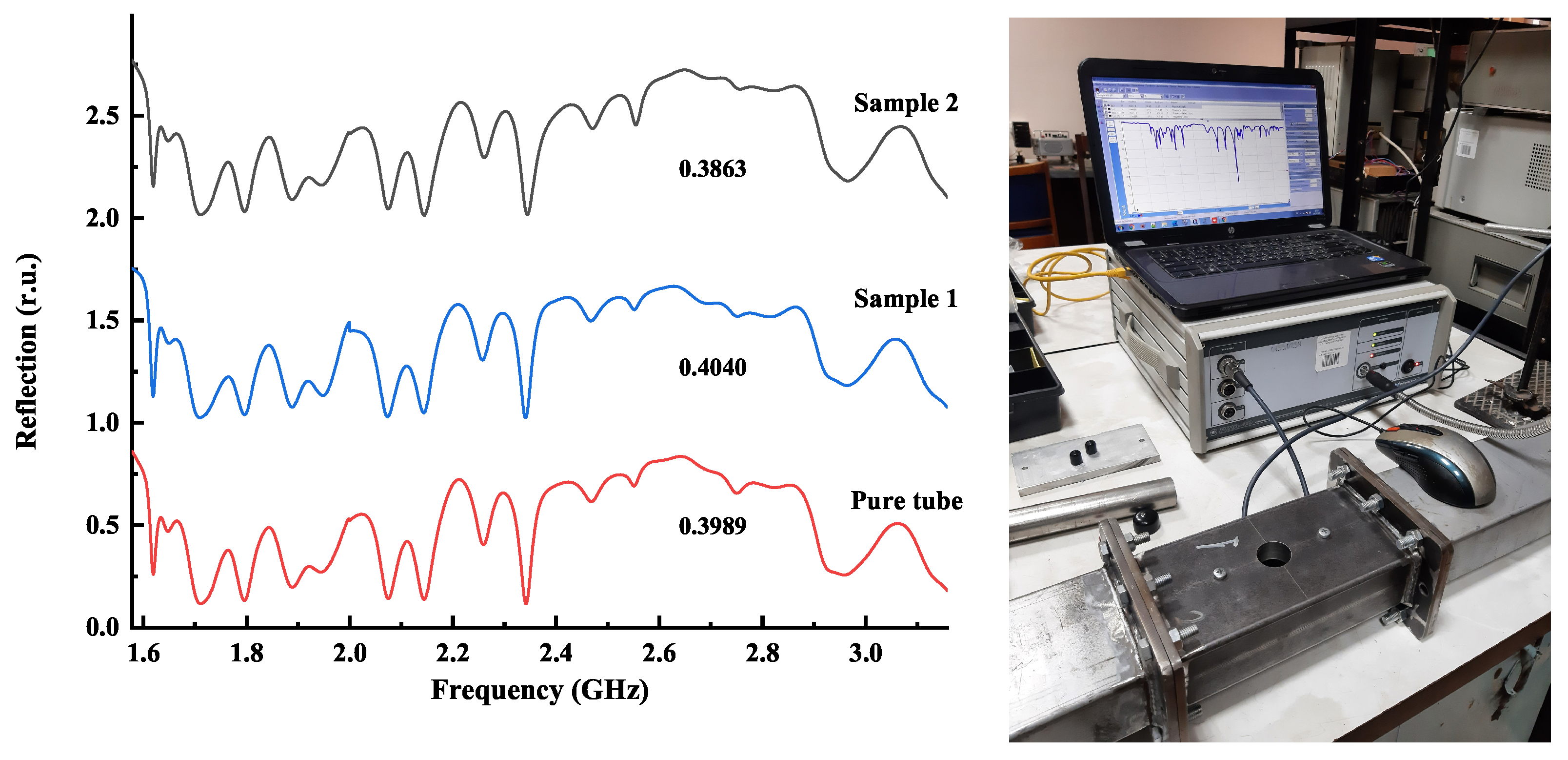
6. Microwave Reflection from Homogeneous and Radially Heterogeneous Pellets

To estimate the power absorbed by the pellet and indirectly compare theoretical results obtained in the previous section with experimental ones, the reflection coefficients from homogeneous and radially heterogeneous pellets were measured in the setup shown schematically in Figure 6b. A scalar network analyzer R2M40 (“Mikran”, Russia) were used for reflection measurements. The sample was placed in the double-ridged waveguide gap on a radio-proof pedestal. In the range 1.579–3.158 GHz (TE10 mode), the values of the reflection coefficient were obtained for an empty cell, pellets with a homogeneous and radially inhomogeneous distribution of EAF dust (Figure 11). Biochar with conductivity equals to 1010 s−1 was used for preparation of the pellets.
The reflection coefficient values shown in the Figure 11 are averaged values over the entire frequency range. It can be seen that the value of the reflection coefficient for a radially heterogeneous pellet is less that for a homogeneous one, which indicates its better absorption capacity. Moreover, the averaged value of reflection coefficient for a heterogeneous pellet coincided with the theoretical value, which is 0.3861, for the pellet shown in Figure 9.

7. Discussion

For the case when the volume fraction of EAF in dust increases linearly from 0 in the core of the pellet to 0.8 in the shell (e.g., there is only biochar in the core, while in the shell there is a proportion of 0.8 EAF in the dust and no biochar), the fastest heating occurred at a biochar conductivity of 1010.6 s−1 (Figure 8). Previously, in [14], almost the same result was achieved for homogeneous pellets of iron oxides (only Fe2O3/Fe3O4) and biochar, for an optimal biochar conductivity of 1011 s−1. In this work, more precise values for the optimal biochar conductivity of EAF dust–biochar pellets were obtained, taking into account the heterogeneous radial distribution of EAF dust within the pellet to achieve an even better absorption of microwave energy by the pellet. It should be noted that in this case, the real part of the permittivity first increases up to half of the radius, then decreases. At the same time, the imaginary part of permittivity already has a sufficient value to enable electric losses in the area where the real part of permittivity changes its behavior. Due to this behavior of effective permittivity, it can be seen in Figure 8c that electromagnetic heat sources tend to stretch along a circle with a radius of 0.5 due to the localization of electromagnetic fields on the line where the behavior of the real part of permittivity changes and electromagnetic waves may experience partial scattering. This technique can be considered to be a way to control the heating of the pellet within its volume.
In Figure 9 at a biochar conductivity equal to 1010 s−1, the heating of pellet is almost identical to that in Figure 8 but a bit less effective, as there is no such scattering effect. At a conductivity of biochar of 1012 s−1, it was expected to see better heating due better electrical losses. However, in Figure 7, it is evident that the pellet has been heated 200 K less than it was at a conductivity of biochar of 1010.6 s−1. All the heat sources in this case are localized in a very small area near the center of the pellet. This is because the imaginary and real parts of permittivity drastically decrease in this case.
Eventually, the less effective but more uniform heating of the pellet when the conductivity of biochar is equal to 108 s−1 can be seen in Figure 10. In this case, the real and imaginary parts of permittivity increase simultaneously, which is not the best case for surface impedance matching. The heat sources are almost uniformly distributed over the whole volume of the pellets, but they are too small and feature a slight accent near the surface. However, it can be seen in Figure 10e that the temperature in the core is almost 60 K more than at the surface. This is due to the surface radiation losses and an insufficient level of heating occurring to replenish them.

8. Conclusions

The dependencies of the effective permittivity and permeability of EAF dust powders on the volume fraction of zinc-containing core–shell particles were calculated. It was considered that zinc-containing and iron-containing particles within EAF dust have a core–shell structure. The dependencies of the effective permittivity and permeability of a biochar–EAF dust–bentonite binder powder mixture on the volume fraction of EAF dust and the conductivity of biochar were calculated. The microwave heating of biochar-containing EAF dust spherical pellet with a radially inhomogeneous distribution of EAF dust within the pellet was simulated and investigated. Conditions where it is possible to achieve a fast and quite uniform volumetric heating of the pellet were obtained. It was experimentally shown that for a pellet with radially heterogeneous distribution of EAF dust, the proportion of electromagnetic radiation that penetrates the pellet is higher than for homogeneous pellet. The measured result correlates with the value obtained from the numerical simulation for conductivity of biochar equal to 1010 s−1. However, numerical simulation shows that if it possible to obtain carbon-containing filler with conductivity of 1010.6 s−1 then absorption characteristics of such a pellet will be better.

Author Contributions

Conceptualization, A.A., A.F. and V.B.; methodology, A.A., L.B., A.F. and D.K.; software, A.A., L.B.; validation, A.A., A.F., Z.P. and V.B; formal analysis, A.A., L.B. and D.K.; investigation, D.P., L.B., D.K. and V.T.; resources, A.A., D.K. and V.B.; data, V.T., L.B. and A.A.; writing—original draft preparation, V.B. and A.A.; writing—review and editing, A.A., D.K. and V.B.; visualization L.B.; supervision, V.B.; project administration, A.A. and Z.P.; funding acquisition, V.B., Z.P. and A.A. All authors have read and agreed to the published version of the manuscript.

Funding

The reported study was funded by Russian Foundation of Basic Research project number 21-58-53044 and supported by the National Natural Science Foundation of China under Grant 52111530046.

Data Availability Statement

Not applicable.

Conflicts of Interest

The authors declare no conflict of interest. The funders had no role in the design of the study, analyses or interpretation of data and the reviewing of the manuscript.

References

  1. Lin, X.; Peng, Z.; Yan, J.; Li, Z.; Hwang, J.Y.; Zhang, Y.; Li, G.; Jiang, T. Pyrometallurgical recycling of electric arc furnace dust. J. Clean Prod. 2017, 149, 1079–1100. [Google Scholar] [CrossRef]
  2. Manturov, D. Prospects of the forest complex in the modern economy. Pulp Pap. Ind. 2017, 2/3, 16–17. [Google Scholar]
  3. Wang, L.; Peng, Z.; Lin, X.; Ye, Q.; Ye, L.; Zhang, J.; Liu, Y.; Liu, M.; Rao, M.; Li, G.; et al. Microwave-intensified treatment of low-zinc EAF dust: A route toward high-grade metallized product with a focus on multiple elements. Powder Technol. 2021, 383, 509–521. [Google Scholar] [CrossRef]
  4. Ye, Q.; Li, G.; Peng, Z.; Augustine, R.; Perez, M.D.; Liu, Y.; Liu, M.; Rao, M.; Zhang, Y.; Jiang, T. Microwave-assisted self-reduction of EAF dust-biochar composite briquettes for production of direct reduced iron. Powder Technol. 2020, 362, 781–789. [Google Scholar] [CrossRef]
  5. Buzin, P.J.W.K.; Heck, N.C.; Vilela, A.C.F. EAF dust: An overview on the influences of physical, chemical and mineral features in its recycling and waste incorporation routes. J. Mater. Res. Technol. 2017, 6, 194–202. [Google Scholar] [CrossRef]
  6. Leclerc, N.; Meux, E.; Lecuire, J.M. Hydrometallurgical recovery of zinc and lead from electric arc furnace dust using mononitrilotriacetate anion and hexahydrated ferric chloride. J. Hazard. Mater. 2002, 91, 257–270. [Google Scholar] [CrossRef]
  7. Kim, E.; Kim, T.; Lee, J.; Kang, Y.; Morita, K. Reduction of electric arc furnace dust by graphite powders under microwave irradiation. Ironmak. Steelmak. 2012, 39, 45–50. [Google Scholar] [CrossRef]
  8. Xia, L.; Mao, R.; Zhang, J.; Xu, X.; Wei, M.; Yang, F. Reduction process and zinc removal from composite briquettes composed of dust and sludge from a steel enterprise. Int. J. Miner. Metall. Mater. 2015, 22, 122–131. [Google Scholar] [CrossRef]
  9. Omran, M.; Fabritius, T. Improved removal of zinc from blast furnace sludge by particle size separation and microwave heating. Miner. Eng. 2018, 127, 265–276. [Google Scholar] [CrossRef]
  10. Omran, M.; Fabritius, T. Utilization of blast furnace sludge for the removal of zinc from steelmaking dusts using microwave heating. Sep. Purif. Technol. 2019, 210, 867–884. [Google Scholar] [CrossRef]
  11. Ye, L.; Peng, Z.; Wang, L.; Anzulevich, A.; Bychkov, I.; Tang, H.; Rao, M.; Zhang, Y.; Li, G.; Jiang, T. Preparation of core-shell iron ore-biochar composite pellets for microwave reduction. Powder Technol. 2018, 338, 365–375. [Google Scholar] [CrossRef]
  12. Ye, Q.; Li, G.; Peng, Z.; Lee, J.; Lin, X.; Rao, X.; Zhang, Y.; Jiang, T. Microwave-assisted self-reduction of composite briquettes of zinc ferrite and carbonaceous materials. Powder Technol. 2019, 342, 224–232. [Google Scholar] [CrossRef]
  13. Ye, Q.; Peng, Z.; Li, G.; Lee, J.; Liu, J.; Liu, M.; Wang, L.; Rao, M.; Zhang, Y. Microwave-Assisted Reduction of Electric Arc Furnace Dust with Biochar: An Examination of Transition of Heating Mechanism. ACS Sustain. Chem. Eng. 2019, 7, 9515–9524. [Google Scholar] [CrossRef]
  14. Anzulevich, A.; Kalganov, D.; Anzulevich, S.; Bychkov, I.; Peng, Z. Optimal microwave heating of biochar containing iron ore pellets. J. Phys. Conf. Ser. 2020, 1461, 012007. [Google Scholar] [CrossRef]
  15. Huang, J.; Liu, Y.; Li, Y.; Liu, X.X. Microwave electromagentic and absorption properties of AFe2O4 (A = Ni, Mn, Zn) ferrites. In Proceedings of the International Conference on Manufacturing Construction and Energy Engineering (MCEE), Hong Kong, China, 17–18 August 2016; pp. 190–196. [Google Scholar]
  16. Srivastava, J.K.; Prasad, M.; Wagner, J.B., Jr. Electrical Conductivity of Silicon Dioxide Thermally Grown on Silicon. J. Electrochem. Soc. 1985, 132, 955–963. [Google Scholar] [CrossRef]
  17. Hotta, M.; Hayashi, M.; Nishikata, A.; Nagata, K. Complex Permittivity and Permeability of SiO2 and Fe3O4 Powders in Microwave Frequency Range between 0.2 and 13.5 GHz. ISIJ Int. 2009, 49, 1443–1448. [Google Scholar] [CrossRef] [Green Version]
  18. Martin, L.P.; Dadon, D.; Rosen, M.; Gershon, D.; Rybakov, K.I.; Birman, A.; Calame, J.P.; Levush, B.; Carmel, Y.; Hutcheon, R. Effects of anomalous permittivity on the microwave heating of zinc oxide. J. Appl. Phys. 1998, 83, 432–437. [Google Scholar] [CrossRef]
  19. Lunt, R.A.; Jackson, A.J.; Walsh, A. Dielectric response of Fe2O3 crystals and thin films. Chem. Phys. Lett. 2013, 586, 67–69. [Google Scholar]
  20. Simonyan, L.M.; Govorova, N.M. Features of dust formation in the oxygen-blowing of melts and possible uses of captured dust. Metallurgist 2011, 55, 450–458. [Google Scholar] [CrossRef]
  21. Anzulevich, A.P.; Bychkov, I.V.; Buchelnikov, V.D.; Anzulevich, S.N.; Kalganov, D.A.; Peng, Z. Calculation of Effective Permittivity and Permeability for Iron Ore–Biochar–Bentonite Binder Powders Mixture. In Proceedings of the 3rd International Conference on Shape Memory Alloys (SMA 2018), Chelyabinsk, Russia, 13–17 September 2018; Volume 9, pp. 136–139. [Google Scholar]
  22. Kalganov, D.A.; Pavlov, D.A.; Anzulevich, A.P.; Butko, L.N.; Tolkachev, V.A.; Peng, Z. Investigation of composition and properties of EAF dust for metal reduction. IOP Conf. Ser. Mater. Sci. Eng. 2021, 1155, 012082. [Google Scholar] [CrossRef]
  23. Potapov, D.S.; Potapov, S.S. Mineralogy of ferrochrome production slags of Chelyabinsk Electrometallurgical Plant. Successes Mod. Nat. Sci. Conf. Mater. 2010, 8, 23–25. [Google Scholar]
  24. Dib, R.; Vincent, D.; Elrafhi, A. Measurement of the electromagnetic properties of thin films using a microwave resonant cavity. ACS Microw. Opt. Technol. Lett. 2019, 61, 15–19. [Google Scholar] [CrossRef]
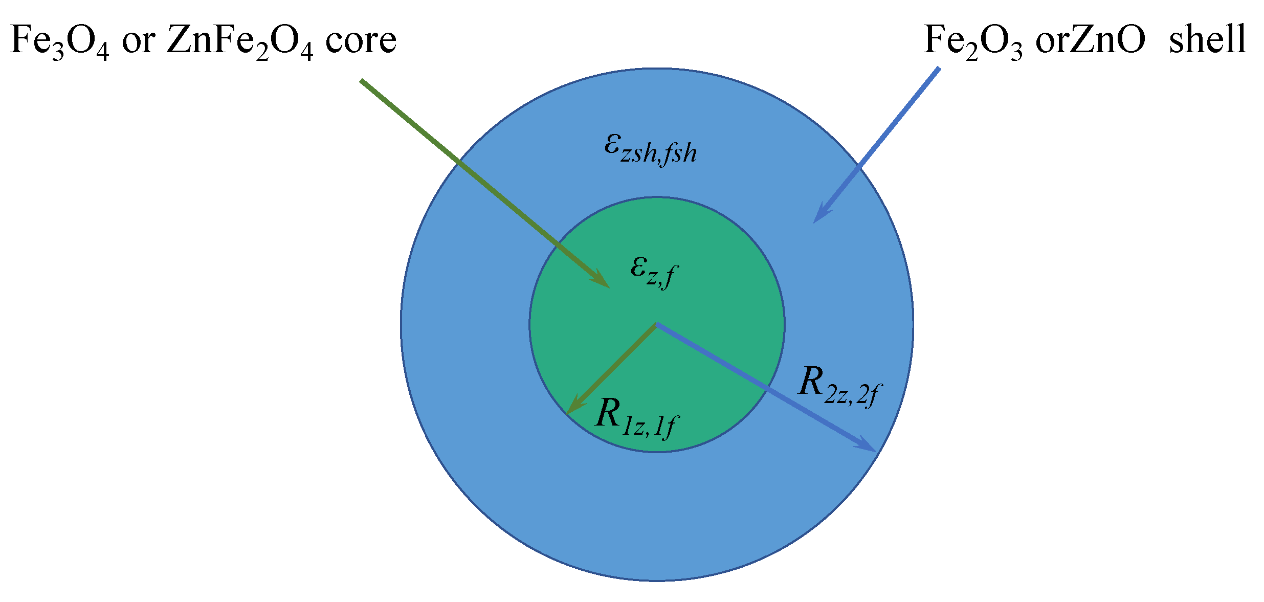
  25. Anzulevich, A.P.; Bychkov, I.V.; Buchelnikov, V.D.; Peng, Z.; Huang, Z.; Xu, B.; Butko, L.N.; Anzulevich, S.N.; Moiseev, S.G. Simplified Core-Shell Model of Biochar-Iron Ore Mixture for Calculation of Effective Permittivity and Permeability. Solid State Phenom. 2018, 279, 240–244. [Google Scholar] [CrossRef]
  26. Ordonez-Miranda, J.; Alvarado-Gil, J.J.; Medina-Ezquivel, R. Generalized Bruggeman Formula for the Effective Thermal Conductivity of Particulate Composites with an Interface Layer. Int. J. Thermophys. 2010, 31, 975–986. [Google Scholar] [CrossRef]
  27. Pietrak, K.; Wisniewski, T.S. A review of models for effective thermal conductivity of composite materials. J. Power Technol. 2015, 95, 14–24. [Google Scholar]
  28. Tripathi, A.; Chandra, H. Performance Investigation of Automobile Radiator Operated with ZnFe2O4 Nano Fluid based Coolant. Matec Web Conf. 2015, 34, 01003. [Google Scholar] [CrossRef] [Green Version]
  29. Olorunyolemi, T.; Birnboim, A.; Carmel, Y.; Wilson, O.C., Jr.; Lloyd, I.K.; Smith, S.; Campbell, R. Thermal conductivity of zinc oxide: From green to sintered state. J. Am. Ceram. Soc. 2002, 85, 1249–1253. [Google Scholar] [CrossRef]
  30. Akiyama, T.; Ohta, H.; Takahashi, R.; Waseda, Y.; Yagi, J.I. Measurement and modeling of thermal conductivity for dense iron oxide and porous iron ore agglomerates in stepwise reduction. ISIJ Int. 1992, 32, 829–837. [Google Scholar] [CrossRef]
  31. Mølgaard, J.; Smeltzer, W.W. Thermal conductivity of magnetite and hematite. J. Appl. Phys. 1971, 42, 3644–3647. [Google Scholar] [CrossRef]
  32. Yao, D.J.; Lai, W.C.; Chien, H.C. Temperature dependence of thermal conductivity for silicon dioxide. Int. Conf. Micro/Nanoscale Heat Transf. 2008, 42924, 435–439. [Google Scholar]
  33. Horai, K.I.; Simmons, G. Thermal conductivity of rock-forming minerals. Earth Planet. Sci. Lett. 1969, 6, 359–368. [Google Scholar] [CrossRef]
  34. Weber, K.; Quicker, P. Properties of biochar. Fuel 2018, 217, 240–261. [Google Scholar] [CrossRef]
  35. Ye, Q.; Peng, Z.; Ye, L.; Wang, L.; Augustine, R.; Lee, J.; Liu, Y.; Liu, M.; Rao, M.; Li, G.; et al. Thermodynamic Analysis of Carbothermic Reduction of Electric Arc Furnace Dust. In Proceedings of the 10th International Symposium on High-Temperature Metallurgical Processing, San Antonio, TX, USA, 10–14 March 2019; pp. 117–124. [Google Scholar]
Figure 1. Schematic illustration of the model of core–shell zinc-containing or iron-containing spherical particles.
Metals 11 01765 g001
Figure 2. Schematic illustration of the experimental setup for permittivity measurement using the method of the partial filling of the resonator.
Metals 11 01765 g002
Figure 3. Real and imaginary parts of effective permittivity ε e f f and ε e f f and permeability μ e f f and μ e f f of EAF dust powder depending on the volume fraction of the zinc-containing core–shell particles p z . Solid line shows ideally compacted powder without pores; dashed line shows bulk density powder with pores.
Metals 11 01765 g003
Figure 4. Real and imaginary parts of the effective permittivity ε and ε and permeability μ and μ of EAF dust–biochar powder mixture depending on the volume fraction of EAF dust ν e a f and biochar conductivity σ b i o c h a r .
Metals 11 01765 g004
Figure 5. Differential scanning calorimetry of powder (a) and the dependency of the effective thermal conductivity on the volume fraction of EAF dust (b).
Metals 11 01765 g005
Figure 6. Analytical calculation of the interaction of the plane wave with spherical pellet (a) and the finite element simulation of the interaction of the H10-mode wave with spherical pellet in a single-mode rectangular waveguide with H-type inserts (b). Here, in the top left is the coaxial cable, which is the source of the wave. In the top right, there is the spherical pellet, located between the H-type inserts in the waveguide to amplify the field strength and heating.
Metals 11 01765 g006
Figure 7. Dependencies of dielectric permittivity (real and imaginary parts) on the volume fraction of EAF dust for a biochar conductivity of σ e a f = 1012 s−1 (a,b). Distribution of heat sources (analytical solution for plane wave in free space) (c), temperature curve (d), and temperature distribution within pellet (e,f).
Metals 11 01765 g007
Figure 8. Dependencies of dielectric permittivity (real and imaginary parts) on the volume fraction of EAF dust for a biochar conductivity of σ e a f = 1010.6 s−1 (a,b). Distribution of heat sources (analytical solution for plane wave in free space) (c), temperature curve (d), and temperature distribution within pellet (e,f).
Metals 11 01765 g008
Figure 9. Dependencies of dielectric permittivity (real and imaginary parts) on the volume fraction of EAF dust for a biochar conductivity of σ e a f = 1010 s−1 (a,b). Distribution of heat sources (analytical solution for plane wave in free space) (c), temperature curve (d), and temperature distribution within pellet (e,f).
Metals 11 01765 g009
Figure 10. Dependencies of dielectric permittivity (real and imaginary parts) on the volume fraction of EAF dust for a biochar conductivity of σ e a f = 108 s−1 (a,b). Distribution of heat sources (analytical solution for plane wave in free space) (c), temperature curve (d), and temperature distribution within pellet (e,f).
Metals 11 01765 g010
Figure 11. Reflection coefficients for pure tube, homogeneous EAF dust–biochar pellet (Sample 1), and radially heterogeneous pellet (Sample 2).
Metals 11 01765 g011
Table 1. Possible content of EAF dust and properties of the components [15,16,17,18,19].
ε σ , s 1 μ μ Weight Fraction, %Model Volume Fraction, %
ZnFe2O43.71.528 × 1091.250.555–5023
ZnO5.8221.798 × 105111–258
Fe3O457.3551.079 × 10101.20.210–6025
Fe2O314.9228.988 × 1041110–2512
SiO261.011 × 101111–102
CaMgSiO48.56.92 × 10−11115–6030
Publisher’s Note: MDPI stays neutral with regard to jurisdictional claims in published maps and institutional affiliations.

