Article

Effects of Water Cooling on the Microstructure of Electron Beam Additive-Manufactured Ti-6Al-4V

1
Institute of Strength Physics and Materials Science of Siberian Branch of Russian Academy of Sciences, 634055 Tomsk, Russia
2
School of Nuclear Science & Engineering, National Research Tomsk Polytechnic University, 634050 Tomsk, Russia
*
Author to whom correspondence should be addressed.
Metals 2021, 11(11), 1742; https://doi.org/10.3390/met11111742
Submission received: 5 October 2021 / Revised: 24 October 2021 / Accepted: 28 October 2021 / Published: 30 October 2021
(This article belongs to the Special Issue Microstructure and Mechanical Properties of Titanium Alloys II)

Abstract

:
The inferior mechanical properties of EBAM Ti-6Al-4V samples are due to the coarse columnar grains containing coarse lamellar structures. One can expect that water cooling of the build platform will increase the cooling rate of the molten pool during the build-up process, causing microstructure refinement. In the present work, the substrate cooling effects on the microstructure and phase composition of EBAM Ti-6Al-4V samples are studied using optical, scanning electron, and scanning transmission microscopy, as well as X-ray diffraction analysis. It is shown that the microstructure of the EBAM Ti-6Al-4V samples built on the substrate without water cooling consists predominantly of columnar prior β grains with lateral sizes ranging up to 2000 µm, while cooling of the build platform causes the appearance of equiaxed prior β grains measuring 1000 µm. Moreover, the refinement of the martensite structure and the precipitation of α′′ martensite platelets within α laths occur in the EBAM Ti-6Al-4V samples built on the water-cooled build platform. An explanation of the mechanisms underlying the α′→α + β and α′→α + α′′ + β transformations during the building process is provided based upon ab initio calculations. The fragmentation of the α laths under the residual compressive stresses is discussed.

1. Introduction

Wire-fed electron beam additive manufacturing (EBAM) (also referred to as Sciaky’s electron beam additive manufacturing or electron beam free form fabrication) is a one-of-a-kind metal additive manufacturing technology used for the fabrication of large-scale, high-value metal parts, as well as for repair and restoration in remanufacturing [1,2,3]. The maximum size of EBAM-fabricated samples is limited only by the size of the vacuum chamber. The most distinctive feature of EBAM is that this method combines extremely high deposition rates with very little material waste [4]. There is also the opportunity to use dual material suppliers to increase the efficiency of the EBAM process [5]. Moreover, a wire is significantly cheaper compared to powder feedstocks, while much wider wire nomenclature is commercially available [6]. Finally, EBAM machines are inexpensive and easy to use, since this method of 3D printing is an adaption of the widespread electron beam welding process.
The most promising application of EBAM is in the 3D printing of parts and components from weldable metals, such as nickel-based alloys, highly-alloyed steels, as well as titanium alloys, which are widely used in aerospace [1], medical [7,8] and other novel industries [6]. A huge number of up-to-date studies have been devoted to the investigation of the surface roughness, microstructure, and mechanical properties of EBAM Ti-6Al-4V titanium alloy, which is one of the most commonly used materials in numerous applications, especially in engine applications, such as in rotors, compressor blades, and hydraulic system components. This is due to its unique properties, such as its low density and high corrosion resistance. All researchers are unanimous in the opinion that the main challenges in the usage and industrial application of layer-by-layer-deposited EBAM Ti-6Al-4V samples are their surface roughness and much coarser columnar prior β grains in comparison with the finer prior β grains in Ti-6Al-4V samples manufactured via selective laser melting (SLM) or electron beam melting (EBM) [3,9,10]. This is due to the low cooling rate of the molten pool as well as the multiple heating and cooling cycles of the underlying solidified layers during the build-up process. As a result, the mechanical properties of EBAM Ti-6Al-4V samples are often inferior to those of SLM and EBM Ti-6Al-4V samples [9,11,12,13].
The microstructure refinement of 3D-printed metal samples can be effectively achieved by: (i) using the ultrasonic vibration method, leading to cavitation in the molten pool [14]; (ii) the introduction of carbide-forming elements, which serve as crystallization centers [15]; (iii) water cooling of the build platform [16,17,18,19,20]; applying water [21] or cooling gas (argon, helium, and their mixture) onto the solidifying top layer during the build-up process [22,23], which withdraws heat from the sample and significantly decrease its temperature.
It is worth noting that most studies on the water cooling effect have focused on steel, aluminum, and nickel-based alloys. It has been shown [16] that the placing of a water-pipe-embedded cooling copper plate at the bottom of a base metal effectively takes much of the heat away during wire-arc additive manufacturing (WAAW) processes. This compulsory cooling provides the possibility to build a thin-walled WAAW part as high as 166 mm by melting a steel–copper-coated welding wire. In contrast, the thin wall part is hard to deposit using air-cooling (i.e., without compulsory cooling), since the molten metal is predisposed due to subsidence at a certain height [16]. According to [17], the compulsory water cooling provides a higher temperature gradient, as well as a higher cooling speed during direct energy deposition (DED). Accordingly, the water cooling promotes epitaxial growth in Ni-based single-crystal superalloys during the DED process.
Only a few studies have been devoted to the water cooling effect on the microstructure of 3D-printed titanium alloys, which are characterized by relatively low thermal conductivity. Particularly noteworthy is the study devoted to underwater wire-fed laser deposition of Ti-6Al-4V titanium alloy [21]. According to [21], the water environment drastically increased the cooling rate of the deposited metal and decreased the dwell time of the temperature. The disadvantage of underwater laser deposition regarding Ti-6Al-4V alloy is its complexity, due to the susceptibility of titanium in water environments [21]. Regarding substrate water cooling, there is a lack of understanding on how to apply water cooling to control the microstructure of EBAM Ti-6Al-4V samples. The present article compares the microstructure of EBAM Ti-6Al-4V samples built on substrates without and with water cooling.

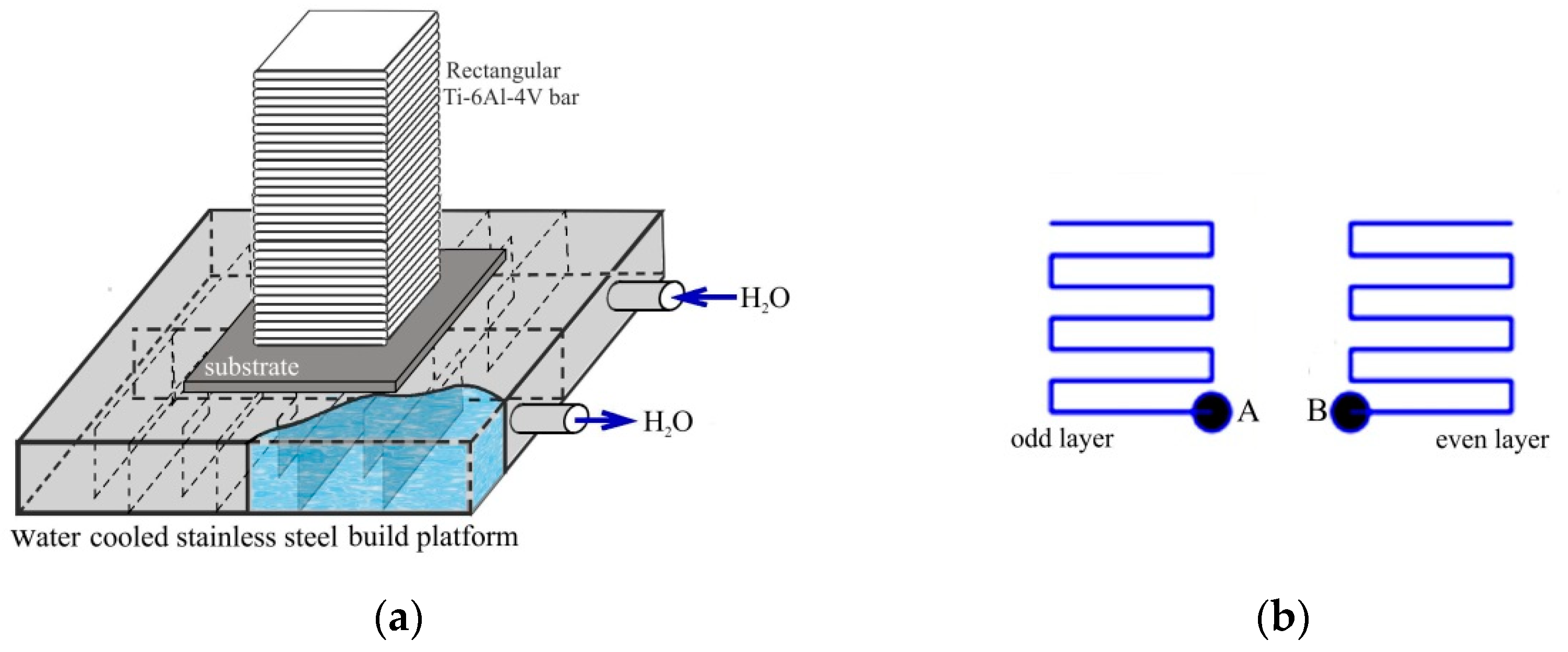
2. Materials and Methods
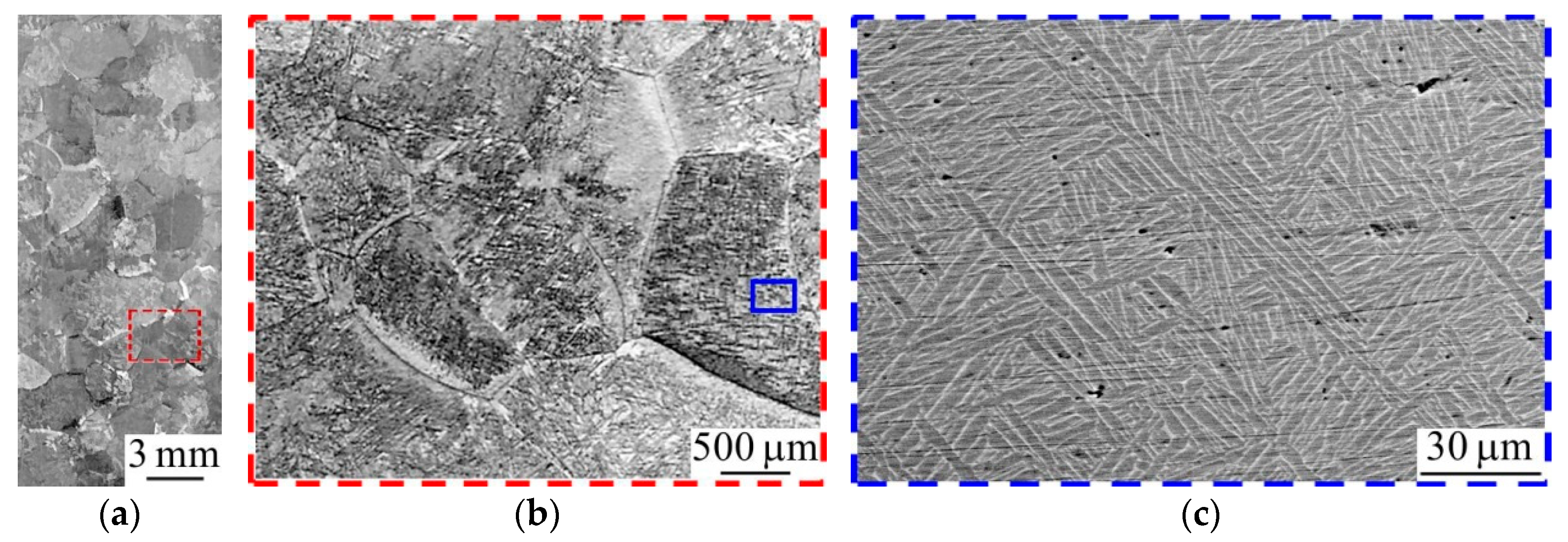
Rectangular Ti-6Al-4V bars measuring 25 mm × 25 mm × 70 mm (length × width × height) were obtained via wire-fed electron beam additive manufacturing using an EBAM machine (ISPMS SB RAS). The Ti-6Al-4V EBAM bars were built on the titanium substrate measuring 150 mm × 150 mm × 10 mm with and without water cooling. The titanium substrate was mounted on a water-cooled stainless steel build platform, where cold water was circulated in the channels (Figure 1a).
Grade 5 titanium wire measuring 1.6 mm in diameter was used as a build material for the EBAM process. The chemical composition of grade 5 titanium wire as examined using energy-dispersive spectroscopy is presented in Table 1. An electron gun with a plasma cathode operating at an accelerating voltage of 30 kV was used to melt the wire. The distance between the source of the electron beam and the substrate was 630 mm. The angle between the substrate and wire was 35°. The wire feed rate was 2 m/min. In total, 22 layers were formed, each 3.2 mm thick. The first three layers were formed at a beam current of 24 mA, which then decreased to 21 mA. Figure 1b shows the deposition strategy of the samples, which consisted of the substrate travelling relative to the electron beam along a meander trajectory with mirror-fused layers at a speed of 4 mm/s. According to Figure 1b, the deposition of each odd layer started from the right bottom corner of the substrate, while the even layer deposition began from the left bottom corner. The distance between the adjacent tracks within the same layer was ~3 mm. After welding each layer, the substrate fixed on the build platform went down by 3 mm. When the building process was over, the rectangular bars were separated from the substrate and cut along the growth direction into 2 mm thick plates using spark cutting.
The microstructure of the wire-fed EBAM Ti-6Al-4V samples was investigated using an Axiovert 40 Mat optical microscope (Carl Zeiss, Göttingen, Germany), a Carl Zeiss EVO 50 scanning electron microscope (SEM, Carl Zeiss, Oberkochen, Germany), and a JEM-2100 transmission electron microscope (TEM, JEOL, Tokyo, Japan) equipped with an Inca ACT-X energy-dispersive X-ray spectroscopy (EDX) detector (Oxford Instruments, Concord, MA, USA). SEM micrographs of the polished samples were obtained with backscattered electrons. The latter allowed us to clearly demonstrate the lamellar α morphology of the dual-phase titanium alloy. The samples for the metallographic examination were subjected to mechanical grinding and polishing followed by etching with Kroll’s reagent. The samples for the TEM investigations were prepared by ion milling of rectangular plates using an Ion Slicer EM-09100IS instrument (JEOL, Tokyo, Japan).
The phase composition of the EBAM Ti-6Al-4V samples was determined at the CCU Innovation Center for Nanomaterials and Nanotechnologies (Tomsk, Russia) with a Shimadzu XRD-7000 X-ray diffractometer (XRD, Shimadzu Corporation, Kyoto, Japan) using CuKα radiation (1.5410 Å wavelength). The XRD studies were performed in a conventional symmetric Bragg–Brentano geometry from 30° to 90° with a scan speed of 1.2°/min. Residual stress measurements were performed using the sin2ψ method [24]. The lattice microstrains (ε) of the samples were calculated using the Williamson–Hall method:
ε = β h k l 4 tan θ ,
where βhkl and θ are the broadening and position of XRD peaks, respectively.
To estimate the effect of the substrate water cooling on the heat input resulting in a decrease in the cooling rate of the molten bath and the microstructure refinement, the following relationship between the prior β grain size (L) and the cooling rate (T) was used [25]:
L = ATn,
where n = 0.93 and A = 3.1 × 106 µm (Ks−1)0.93 ± 0.12. The relationship was predicted for the Ti-6V-4Al alloy on the basis of classical homogeneous nucleation and isotropic linear growth during solidification [26].
Calculations of the atomic structures of α, β and α‘‘ phases of Ti doped with V were performed using the projector-augmented wave and density functional theory [27,28]. For the exchange correlation functional, the generalized gradient approximation in the form of GGA-PBE was used [29]. A plane wave cutoff energy of 300 eV was employed throughout the calculations. Calculations were performed for metal containing 0, 6.6, 13.2, 26.2, and 52.4 wt.% V using (1 × 1 × 1), (2 × 2 × 2), (2 × 2 × 1), (2 × 1 × 1). and (1 × 1 × 1) supercells for both α and β phases; and (1 × 1 × 1), (2 × 1 × 2), (2 × 1 × 1), (1 × 1 × 1), and (1 × 1 × 1) with two impurity atoms for the α‘‘ phase. The atomic positions and the volumes of supercells were optimized.

3. Results

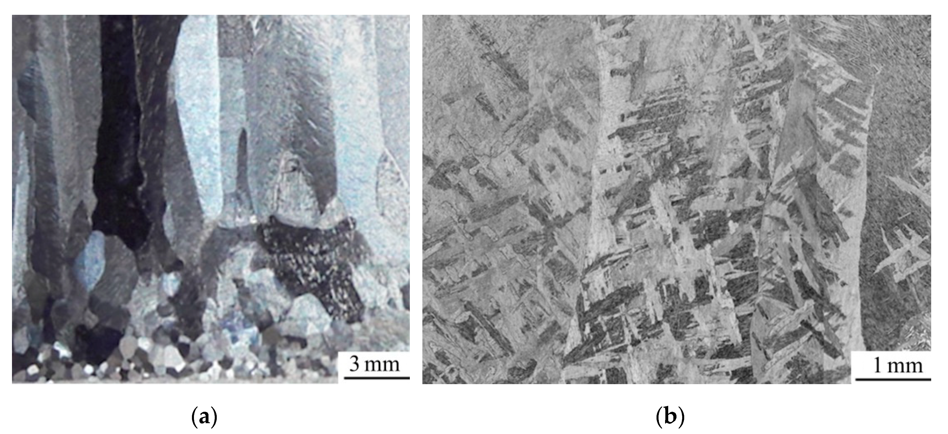
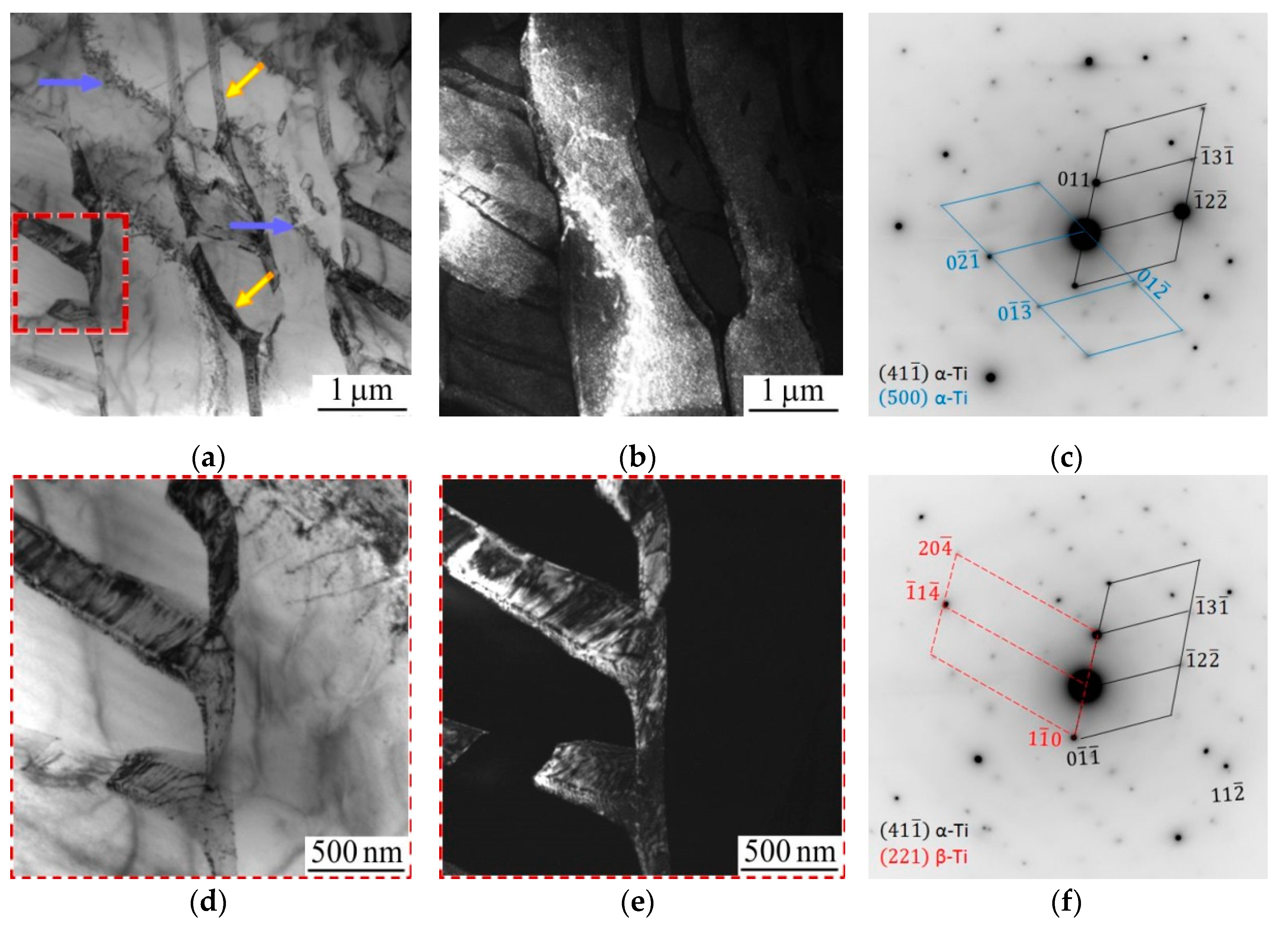
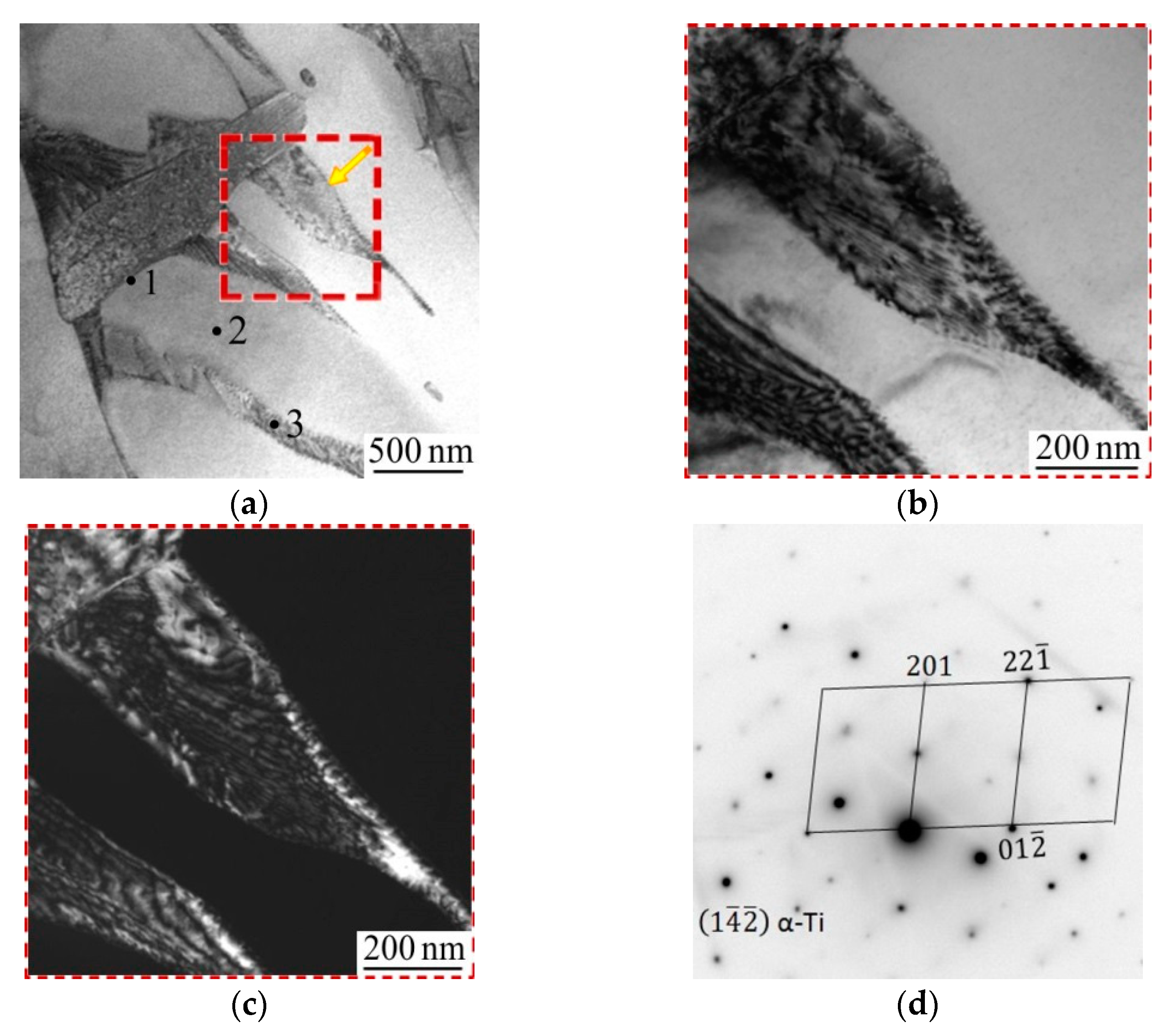
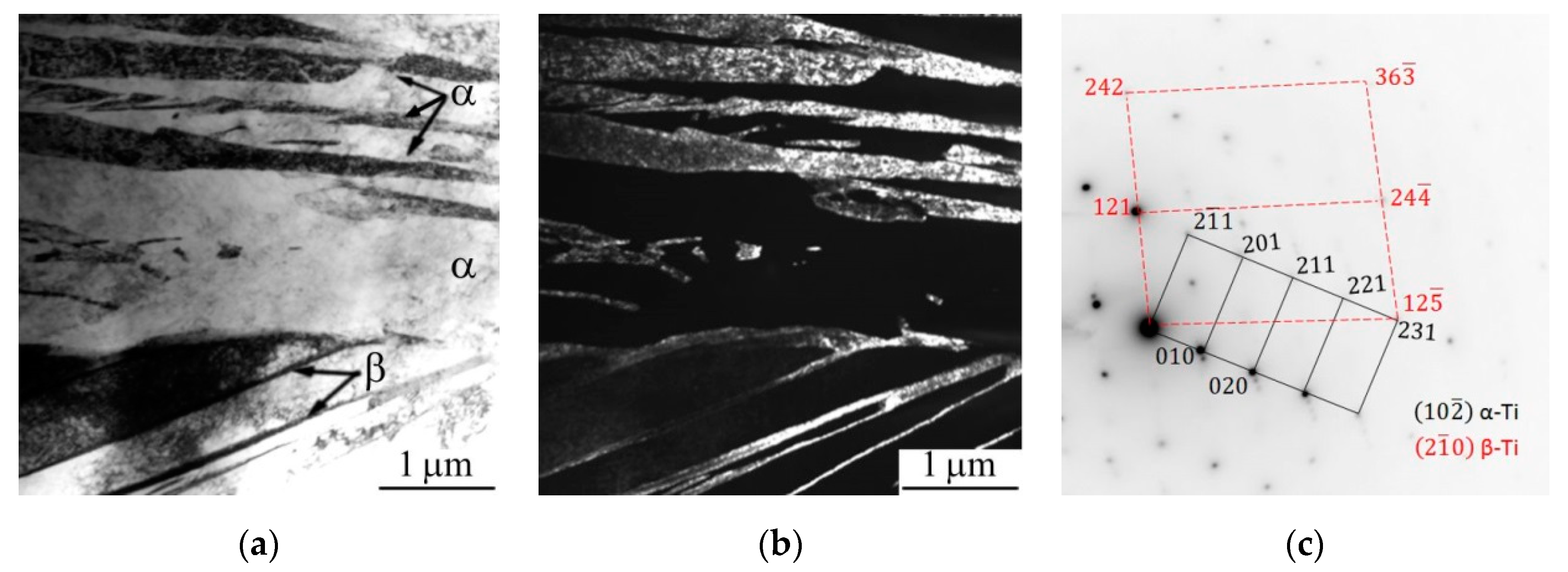
3.1. Microstructure of EBAM Ti-6Al-4V Samples Produced without Substrate Cooling

The microstructure of the EBAM Ti-6Al-4V samples produced without substrate cooling was composed of prior β grains and lamellas of the α phase. In Figure 2, the equiaxed prior β grains can be observed in the lower part of the rectangular Ti-6Al-4V bar, at up to 5 mm in height, while columnar grains appear in the center and upper parts of the bar (Figure 2a). The average size of the equiaxed prior β grains was less than 500 µm, while the columnar grains had a lateral size range of 1500 to 2000 µm and their height exceeded 20 mm.
The main parts of the columnar grains located at a distance of more than 5 mm from the substrate tended to a form colony structure, which consisted of 2-µm-thick α laths (Figure 2b and Figure 3a), while some areas of the grains were characterized by the basket weave microstructure (Figure 3b). It is worth noting that shearing and fragmentation of the laths were revealed in some areas of the EBAM Ti-6Al-4V samples (Figure 3c).
The fine secondary α laths with a thickness of 300–500 nm separated by the retained β phase were also observed in the EBAM Ti-6Al-4V samples produced without substrate cooling (Figure 4). According to Figure 4, each lath has the same orientation within the colony. The EDX data presented in Table 2 show that the vanadium content in the α laths is equal to 2.7 wt.% (point 1 in Figure 4a), while its content in the thin interlayer of the retained β phase reaches 21.7 wt.%, (points 2 and 3 in Figure 4a).
A distinctive feature of the microstructure of the EBAM Ti-6Al-4V samples is the fragmented coarse α laths. Figure 5 clearly demonstrates that the fragmentation occurs via the formation of disoriented regions both close to the lath boundaries (marked by the yellow arrows in Figure 5a) and within the laths (marked by the blue arrows in Figure 5a). The disoriented regions look in the TEM micrographs like thick boundary interlayers of the retained β phase. However, this is not the case, since the disoriented regions are observed only in the dark-field TEM micrographs obtained with α-Ti reflections (Figure 5b). The average width of the disoriented regions appears to be ~200 nm, i.e., they are few times thicker than the layer of the retained β phase. It is also significant that the edges of the disoriented regions are curved and the vanadium content in the regions does not exceed 3 wt.%.
According to Figure 5d,e and Figure 6, the disoriented regions in the coarse α laths consisted of a periodic array of dislocations. A distinctive feature of the regions is their curved boundaries. Moreover, a large number of extinction contours are clearly visible within the regions, indicating a high level of internal stresses and lattice distortions. Our experiments also highlight that the fragmentation of α laths starts from their edges and then spreads toward the bulk of the laths, as demonstrated in Figure 6a. It can be seen from Table 3, which presents the results of the EDX studies, that the phase boundaries, where the fragmentation of α laths starts, are enriched with vanadium (point 1 in Figure 6a), i.e., the phase boundaries most likely could be the retained β phase. Meanwhile, the vanadium content in both α laths and disoriented regions is significantly lower (points 2 and 3 in Figure 6a).

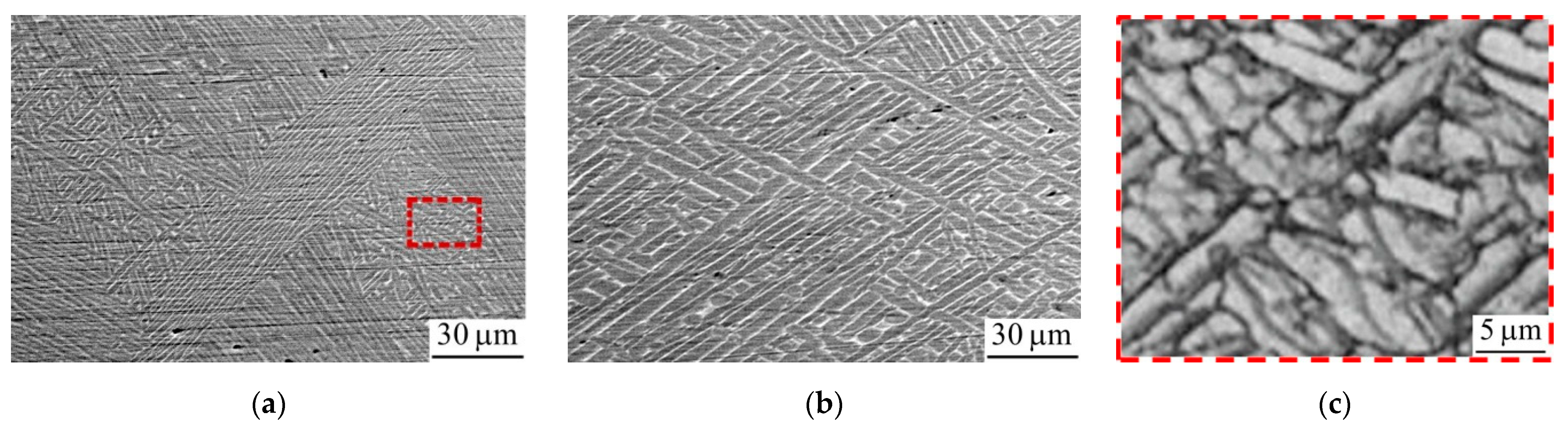
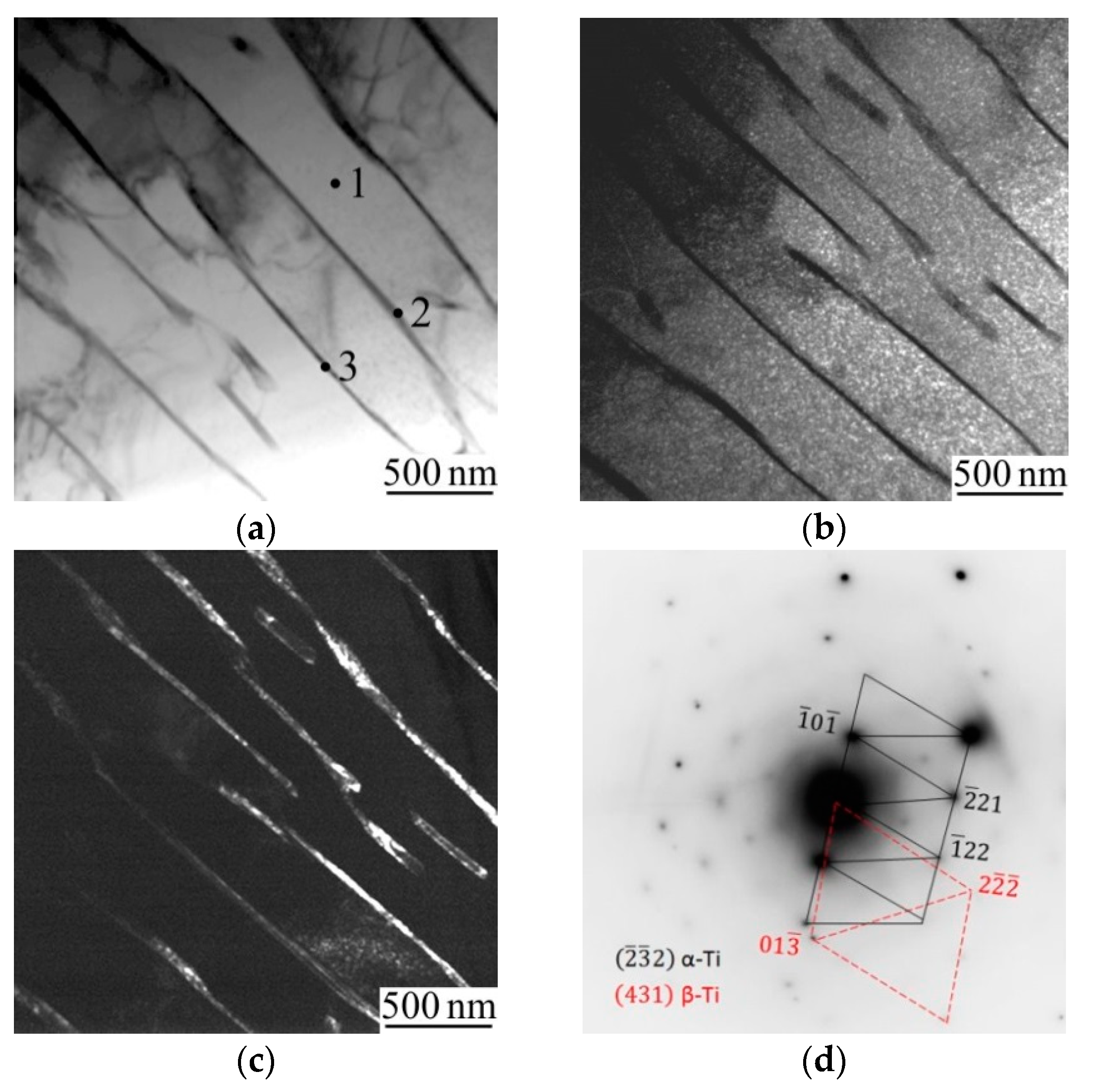
3.2. Microstructure of the EBAM Ti-6Al-4V Samples Produced with Substrate Cooling

Cooling of the titanium substrate during the EBAM process provides a homogeneous grain microstructure along the height of the rectangular Ti-6Al-4V bar. It can be seen from Figure 7a,b that the EBAM Ti-6Al-4V samples produced with substrate cooling were characterized by equiaxed prior β grains, with their size varying from 1000 to 2000 µm. A regular Widmanstätten pattern of α plates with a size of several microns can be observed within the prior β grains (Figure 7c).
Secondary α laths with their size limited by the boundaries of early martensite laths were also revealed in the TEM study (Figure 8). The comparison of Figure 4 and Figure 8 shows that water cooling does not affect the sizes of the α laths and β interlayers. Moreover, fragmentation of the α laths was also observed. The latter manifests itself as curved disoriented regions in the α laths, which are 200 to 500 nm wide. It is worth noting that the extinction contours on TEM images of the EBAM Ti-6Al-4V samples produced with substrate cooling are less pronounced.
It worth noting that the EBAM Ti-6Al-4V samples produced with substrate water cooling contained an α″-Ti phase with an orthorhombic crystal lattice (Figure 9). The precipitation of α″-martensite platelets within the α laths is marked by an arrow in Figure 9c. The interspacing between the α″ plates was less than 100 nm.

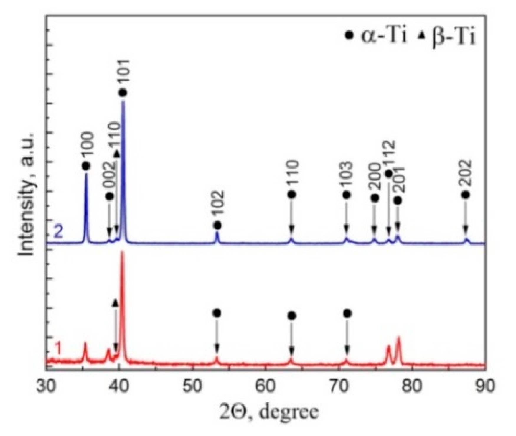
3.3. X-ray Diffraction Analysis
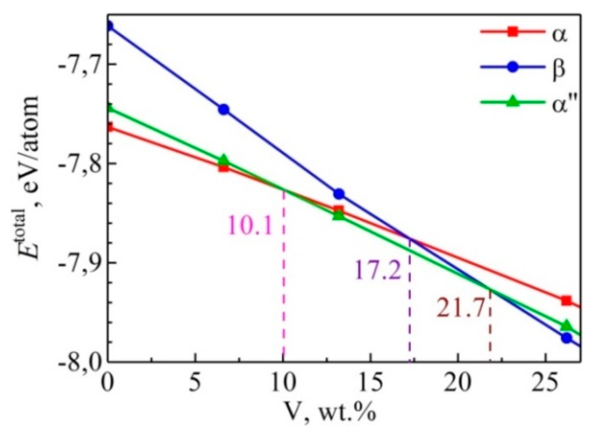
XRD patterns of the EBAM Ti-6Al-4V samples produced with and without substrate cooling are presented in Figure 10. It can be seen from the XRD pattern that a less pronounced <101> texture is beneficial to the EBAM Ti-6Al-4V samples built with water cooling (Figure 10, curve 2). The volume fractions of the β-Ti phase in both samples were equal to 4%. Due to its small amount, the α″-martensite phase was not revealed by the XRD analysis.
The XRD results also exhibit that α-Ti peaks shifted to lower 2θ values, which could be generally attributed to compressive stresses developed in both samples. The measured compressive stress in the EBAM Ti-6Al-4V samples produced without substrate cooling was about 900 MPa, while the water cooling provided compressive stress in the samples at as low as 200 MPa. Microstrains in the EBAM Ti-6Al-4V samples produced without substrate cooling were equal to 0.000280%, which was substantially lower than in the samples produced with substrate cooling (0.000657%).

4. Discussion

The cooling rate and cooling path of the molten pool formed during the additive manufacturing process control the microstructure of 3D-printed metal parts. For EBAM Ti-6Al-4V samples, these parameters particularly affect the size and shape of prior β grains, which are epitaxial and extended along the build direction, so that their height is much bigger than the thickness of each built layer. Generally, the nucleation and growth of the grains are governed by the effectiveness of heat removal from the molten pool. During the EBAM process, the majority of the heat is transferred to the underlying layers beneath the molten pool. Since the heat transfer in titanium is weak due to its rather low thermal conductivity, the heating and re-melting of the underlying layers occur. Actually, liquid phase epitaxial growth of new building layers occurring in the build direction is responsible for the appearance of the columnar prior β grains.
The heat transfer is most intense and the solidification rate of molten pool is the highest at the early stages of the EBAM process, i.e., when the molten pool is located close to the massive and still cold substrate. This is why the microstructure of the bottom part of the rectangular Ti-6Al-4V bar is composed of the equiaxed prior β grains with the minimum size (500 µm). The estimations using Equation (2) revealed that the cooling rate of the molten bath during the deposition of first layers is equal to 1.2 × 10⁴ K/s. During the EBAM process, when moving away from the substrate, the cooling rate gradually decreases, causing the microstructure to consist of predominantly columnar prior β grains with lateral sizes up to 2000 µm. The values correspond to cooling rates as low as 2 × 10³ K/s. Water cooling of the build platform was found to increase the solidification rate of the molten pool. The latter manifests itself as the appearance of equiaxed prior β grains as small as 1000 µm in the central and upper parts of the bar. According to Equation (2), the water cooling doubles the cooling rate of the molten pool formed during EBAM process up to 5 × 10³ K/s. It is obvious that the variations in processing parameters (i.e., electron beam power, scan speed, and hatch spacing) make it possible to change the width and depth of the molten bath [30,31,32] and to somehow further reduce the cooling rate. Nevertheless, the estimated values were significantly lower in comparison with EBM processes (103–105 K/s) [33,34] and especially with SLM processes (106−108 K/s) [35,36]. That is why, in the latter case, the Ti-6Al-4V SLM sample featured columnar grains as small as 100 μm wide [35].
Under cooling of the EBAM Ti-6Al-4V samples from above the β-transus temperature, α-nuclei start to crystallize at the boundaries of the prior β grains and then grow into the bulk of the grains following Burger’s relationship. The cooling rate controls the morphology of the α phase via changes in the nucleation rate and diffusion time. The higher the cooling rate, the higher the driving force for nucleation but the lower the available time for thermally activated diffusion. Since the cooling rate of the molten pool exceeded 410 °C/s, one could expect the formation of a martensitic α′ phase in the sample upon cooling from the β phase to the (α + β) phase region [37]. Indeed, the microstructures of EBM and SLM Ti-6Al-4V samples usually consist of an acicular martensite α′ phase within the prior β grains. The subsequent decomposition of the α′ phase evidently occurs during the EBAM process. The driving force for the decomposition is controlled by vanadium diffusion, which depends on the temperature. According to [38], holding the Ti-6Al-4V titanium alloy at a temperature of about 700 °C for 30 min results in full decomposition of the martensite α′ phase. This transformation is most possible in the layers beneath the molten pool, which undergo repeated heating and cooling during the EBAM process.
Since the water-cooled build platform affects the holding time of the underlying layers at elevated temperatures, two different types of the α′ phase decomposition in the EBAM Ti-6Al-4V samples may occur, i.e., α′→α + β and α′→α + α′′ + β. In both cases, the α′ phase decomposes similarly to the tempering of any martensite at elevated temperatures, resulting in the diffusion-controlled formation of β phase interlayers at α lath boundaries. It is evident, that during the EBAM process without water cooling, the α′ phase decomposition is fully completed, while in the case of water cooling, the decomposition is not completed.
It is interesting to mention at this point that there is no evidence of the α′′ phase formation process in as-built SLM Ti-6Al-4V samples. During the SLM process, the α′ phase decomposition does not occur due to rapid solidification of the molten pool. The formation of the α′′ phase in SLM samples has, however, been observed after heat treatment within the temperature range of 750—900 °C [39]. Unlike SLM, the base metal plate and the Ti-6Al-4V powder is preheated to above 600 °C during the EBM process. Hence, the α′′ phase induced by the α′ phase decomposition has occasionally been found in 3D-printed Ti-6Al-4V alloy samples produced using layer-by-layer electron beam melting of titanium powder in a powder-bed-type metal additive machine [40,41].
The prior β phase formed during initial solidification as well as the martensitic α′ phase formed in the prior β grains by diffusionless β→α′ transformation are characterized by the same vanadium content as the prior β (i.e., ~4 wt.%), unlike the α phase, in which the solubility of vanadium does not exceed 2.7 wt.%. During the subsequent α′ phase decomposition, the appearance of the α phase is accompanied by a local gradual increase in the vanadium content. According to ab initio calculations (this result will be published soon in more details), the formation of the α′′ phase in Ti-6Al-4V titanium alloy is energetically favorable when the content of vanadium ranges from 10.1 to 21.7 wt.% (Figure 11). Consequently, while the α′ phase decomposition is not fully completed, the high vanadium content in the supersaturated α phase may be enough for the formation of the α′′ phase but not enough for the formation of the β phase in the layers underlying the molten pool.
The mechanism underlying the α′→α′′ transformation is well known. As the solute element content increases, the distortion of the hexagonal α‘ martensite occurs. As a result, the α‘ martensite loses its hexagonal symmetry and the orthorhombic α‘‘ phase is formed [42,43]. In our experiments, the higher lattice distortion of the EBAM Ti-6Al-4V samples is attributed to the higher cooling rate. The high microstrains are direct evidence of the high local lattice distortion in the EBAM Ti-6Al-4V samples produced with substrate cooling.
Unlike microstrains, the residual stresses in the EBAM Ti-6Al-4V samples produced with substrate water cooling are 3 times lower than those in the samples produced without substrate cooling. The generation of residual stresses in as-build 3D-printed metal parts is usually explained in terms of the temperature gradient mechanism. During the build-up, upon the formation of the molten pool (liquid layer B in Figure 12a) in the layer beneath the molten pool (layer A in Figure 12a) heats up and expands. Since the expansion of layer A is partially restrained by the surrounding material, the layer is subjected to compression. During subsequent cooling, layer B is prone to shrinkage after its crystallization. Since the shrinkage of the crystallized layer B is constrained by underlayer A, layer B is subjected to tension while layer A undergoes compression. As the next layer builds (liquid layer C in Figure 12c), underlayer B experiences high-temperature reheating, which causes reverse expansion. As a result, the tensile stress in layer B converts into compressive stress, which is enhanced upon subsequent crystallization of layer C followed by its shrinkage, while the upper crystallized layer C is subject to tension.
The temperature gradient successfully describes the generation of compressive residual stresses in additively manufactured components, especially in their central parts [44,45]; however, it does not quantitatively explain the effects of water cooling on the residual stresses revealed in this work. It is obvious that the microstructure of the build parts is the key ingredient in the effects of water cooling on the magnitude of residual stresses developed during the 3D printing process. The microstructure can be taken into account on the basis of the kinetic model [46], which describes the effects of residual stresses in the growing layer on the diffusion flux of atoms along grain boundaries, wherein the movement of the atoms is controlled by the value of the chemical potential at the grain boundaries. As can be seen in Figure 12a, the thermally expanded layer A of the rectangular building bar is subjected to compression during the molten pool formation above it (layer B). The compressive stresses gradually increase the value of the chemical potential at the grain boundaries in layer A. As a result, the diffusion flux of atoms along the grain boundaries occurs outside layer A. The flux directed toward the “liquid top layer B–crystallized underlayer A” interface causes a decrease in the density of layer A, and accordingly a decrease in residual compressive stresses therein. One would expect that the magnitude of the compressive stresses in the EBAM Ti-6Al-4V samples produced with substrate cooling, which were characterized by smaller grain sizes, and accordingly a higher density of grain boundaries, should be lower compared to the samples without water cooling.
The relaxation of compressive residual stresses is also the main reason for the fragmentation of the coarse α laths observed in the EBAM Ti-6Al-4V samples under study. It is worth noting that the same fragmentation pattern was previously observed in [13], whereby the microstructure of wire-fed EBAM Ti-6Al-4V samples was studied in detail. However, we believe that the authors of [13] misinterpreted these disoriented regions within α laths as a residual β phase. Otherwise, it is difficult to explain the continuously decreasing and increasing volume fractions of the α and β phases, respectively, during layer-by-layer deposition. Clearly, the relatively low content of vanadium (4 wt.%), i.e., the beta-stabilizing element, is not able to provide the retained beta phase in the EBAM Ti-6Al-4V samples, which can be as high as 23% [13]. Evidently, the results in [13] suggest that the fragmentation of α laths is also the reason why the average width of the α laths decreases along the building direction.
As mentioned above, the value of compressive residual stresses in the EBAM Ti-6Al-4V samples gradually increases with increasing building height. When the compressive stress reaches the compressive yield strength, the compressive strain occurs via the movement of dislocation through alternating α laths and β interlayers. The accumulation of mobile dislocations in α lath boundaries continuously increases their boundary misorientation [47]. Obviously, the formation of disoriented regions both close to the lath boundaries and within the laths in the EBAM Ti-6Al-4V sample is coincident with continuous dynamic recrystallization, which is attributed to the hot deformation of titanium alloys with lamellar microstructures [48]. The SLM samples with thinner α laths show higher flow stress and increasing deformation resistance. This is why fragmentation of the acicular α′ martensite was not even observed in the extremely stressed as-built SLM Ti-6Al-4V samples, the microstructure of which contained a large amount of the acicular α′ martensite owing to the extremely high cooling rate.

5. Conclusions

Optical, scanning electron, and scanning transmission microscopy, as well as X-ray diffraction measurements, were conducted to compare the microstructure and phase compositions of wire-fed EBAM Ti-6Al-4V samples built on a substrate with and without water cooling. It was shown that the columnar prior β grains with lateral sizes up to 2000 µm made their appearance in the center and upper parts of the rectangular Ti-6Al-4V bars produced without substrate cooling. The microstructure of the EBAM Ti-6Al-4V samples built on the substrate with water cooling consisted of equiaxed prior β grains, with sizes ranging from 1000 to 2000 µm. By using the relationship between the prior β grain size and the cooling rate, we argued that the water cooling doubles the cooling rate of the molten pool during the EBAM process. However, we can state that the effect of the water cooling of the build platform on the microstructure of the EBAM Ti-6Al-4V samples is much weaker as compared to the effect of the water environment. In the latter case, the width of the columnar prior β grains is less than 200 µm [21].
Upon repeated heating and cooling during the EBAM process, the decomposition of the martensite α′ phase occurs in the prior β grains. Due to the different cooling rate, the EBAM Ti-6Al-4V samples produced without substrate water cooling were found to contain colony and basket weave structures, while the Widmanstätten α microstructure was clearly observed in the EBAM Ti-6Al-4V samples built on the water-cooled build platform. Since the decomposition was not complete during water cooling, the α′′ phase precipitated within the α laths.
The effects of water cooling on the strain and stresses in the EBAM Ti-6Al-4V samples were demonstrated. It was shown that the high microstrains in the EBAM Ti-6Al-4V samples could be attributed to the higher cooling rate. The residual stresses in the EBAM Ti-6Al-4V samples produced with substrate water cooling were 3 times lower than those in the samples produced without substrate cooling.
The mechanism of the generation of residual stresses in the EBAM sample accounting for their microstructure has been discussed, suggesting that the value of the chemical potential at the grain boundaries controls the diffusion flux of atoms from the “liquid top layer–crystallized underlying layer” interface to the sample. When the compressive stress reaches the compressive yield strength, the compressive strain occurs via the shearing and fragmentation of primary coarse α laths. The latter manifests itself as the formation of disoriented regions both close to the α lath boundaries and within the laths.

Author Contributions

Conceptualization, A.P.; ab initio calculation, A.B. and S.K.; investigation, M.K., S.M., L.K., O.P. and E.S.; writing—original draft preparation, A.P. and M.K.; writing—review and editing, A.P. All authors have read and agreed to the published version of the manuscript.

Funding

The work has been carried out at the financial support of the Russian Science Foundation (grant No. 21-19-00795).

Institutional Review Board Statement

Not applicable.

Informed Consent Statement

Not applicable.

Data Availability Statement

The data presented in this study are available on request from the corresponding author.

Conflicts of Interest

The authors declare no conflict of interest.

References

  1. Ding, D.; Pan, Z.; Cuiuri, D.; Li, H. Wire-feed additive manufacturing of metal components: Technologies, developments and future interests. Int. J. Adv. Manuf. Technol. 2015, 81, 465–481. [Google Scholar] [CrossRef]
  2. Fuchs, J.; Schneider, C.; Enzinger, N. Wire-based additive manufacturing using an electron beam as heat source. Weld. World 2018, 62, 267–275. [Google Scholar] [CrossRef] [Green Version]
  3. Wanjara, P.; Watanabe, K.; De Formanoir, C.; Yang, Q.; Bescond, C.; Godet, S.; Brochu, M.; Nezaki, K.; Gholipour, J.; Patnaik, P. Titanium Alloy Repair with Wire-Feed Electron Beam Additive Manufacturing Technology. Adv. Mater. Sci. Eng. 2019, 2019. [Google Scholar] [CrossRef] [Green Version]
  4. Taminger, K.M.; Hafley, R.A. Electron Beam Freeform Fabrication for Cost Effective Near-Net Shape Manufacturing. Nato AVT. 2006, 139, 1–9. [Google Scholar]
  5. Davis, A.E.; Breheny, C.I.; Fellowes, J.; Nwankpa, U.; Martina, F.; Ding, J.; Machry, T.; Prangnell, P.B. Mechanical performance and microstructural characterisation of titanium alloy-alloy composites built by wire-arc additive manufacture. Mater. Sci. Eng. A 2019, 765, 138289. [Google Scholar] [CrossRef]
  6. Džugan, J.; Novy, Z. Powder Application in Additive Manufacturing of Metallic Parts. In Powder Metallurgy—Fundamentals and Case Studies; IntechOpen: London, UK, 2017. [Google Scholar]
  7. Ishfaq, K.; Rehman, M.; Khan, A.R.; Wang, Y. A review on the performance characteristics, applications, challenges and possible solutions in electron beam melted Ti-based orthopaedic and orthodontic implants. Rapid Prototyp. J. 2021. ahead-of-print. [Google Scholar] [CrossRef]
  8. Ding, L.; Tan, S.; Chen, W.; Jin, Y.; Zhang, Y. Manufacturability analysis of extremely fine porous structures for selective laser melting process of Ti6Al4V alloy. Rapid Prototyp. J. 2021, 27, 1523–1537. [Google Scholar] [CrossRef]
  9. Panin, A.V.; Kazachenok, M.S.; Panin, S.V.; Berto, F. Scale levels of quasi-static and dynamic fracture behavior of Ti-6Al-4V parts built by various additive manufacturing methods. Theor. Appl. Fract. Mech. 2020, 110, 102781. [Google Scholar] [CrossRef]
  10. Pixner, F.; Warchomicka, F.; Peter, P.; Steuwer, A.; Colliander, M.H.; Pederson, R.; Enzinger, N. Wire-based additive manufacturing of Ti-6Al-4V using electron beam technique. Materials 2020, 13, 3310. [Google Scholar] [CrossRef] [PubMed]
  11. Herzog, D.; Seyda, V.; Wycisk, E.; Emmelmann, C. Additive manufacturing of metals. Acta Mater. 2016, 117, 371–392. [Google Scholar] [CrossRef]
  12. Zhang, Y.; Wu, L.; Guo, X.; Kane, S.; Deng, Y.; Jung, Y.G.; Lee, J.H.; Zhang, J. Additive Manufacturing of Metallic Materials: A Review. J. Mater. Eng. Perform. 2018, 27, 1–13. [Google Scholar] [CrossRef] [Green Version]
  13. Xu, J.; Zhu, J.; Fan, J.; Zhou, Q.; Peng, Y.; Guo, S. Microstructure and mechanical properties of Ti–6Al–4V alloy fabricated using electron beam freeform fabrication. Vacuum 2019, 167, 364–373. [Google Scholar] [CrossRef]
  14. Yuan, D.; Shao, S.; Guo, C.; Jiang, F.; Wang, J. Grain refining of Ti-6Al-4V alloy fabricated by laser and wire additive manufacturing assisted with ultrasonic vibration. Ultrason. Sonochem. 2021, 73, 105472. [Google Scholar] [CrossRef] [PubMed]
  15. Panin, A.V.; Kazachenok, M.S.; Sinyakova, E.A.; Builuk, A.O.; Martynov, S.A.; Panin, S.V.; Berto, F. Improving mechanical properties of wire-based EBAM Ti-6Al-4V parts by adding TiC powders. Mater. Des. Process. Commun. 2021, 3. [Google Scholar] [CrossRef] [Green Version]
  16. Lu, X.; Zhou, Y.F.; Xing, X.L.; Shao, L.Y.; Yang, Q.X.; Gao, S.Y. Open-source wire and arc additive manufacturing system: Formability, microstructures, and mechanical properties. Int. J. Adv. Manuf. Technol. 2017. [Google Scholar] [CrossRef]
  17. Nie, J.; Chen, C.; Liu, L.; Wang, X.; Zhao, R.; Shuai, S.; Wang, J.; Ren, Z. Effect of substrate cooling on the epitaxial growth of Ni-based single-crystal superalloy fabricated by direct energy deposition. J. Mater. Sci. Technol. 2021, 62, 148–161. [Google Scholar] [CrossRef]
  18. Kulkarni, J.D.; Goka, S.B.; Parchuri, P.K.; Yamamoto, H.; Ito, K.; Simhambhatla, S. Microstructure evolution along build direction for thin-wall components fabricated with wire-direct energy deposition. Rapid Prototyp. J. 2021, 27, 1289–1301. [Google Scholar] [CrossRef]
  19. Utyaganova, V.R.; Filippov, A.V.; Shamarin, N.N.; Vorontsov, A.V.; Savchenko, N.L.; Fortuna, S.V.; Gurianov, D.A.; Chumaevskii, A.V.; Rubtsov, V.E.; Tarasov, S.Y. Controlling the porosity using exponential decay heat input regimes during electron beam wire-feed additive manufacturing of Al-Mg alloy. Int. J. Adv. Manuf. Technol. 2020, 108, 2823–2838. [Google Scholar] [CrossRef]
  20. Khoroshko, E.; Filippov, A.; Tarasov, S.; Shamarin, N.; Moskvichev, E.; Fortuna, S.; Lychagin, D.V.; Kolubaev, E. Strength and ductility improvement through thermomechanical treatment of wire-feed electron beam additive manufactured low stacking fault energy (SFE) aluminum bronze. Metals 2020, 10, 1568. [Google Scholar] [CrossRef]
  21. Fu, Y.; Guo, N.; Zhou, L.; Cheng, Q.; Feng, J. Underwater wire-feed laser deposition of the Ti–6Al–4V titanium alloy. Mater. Des. 2020, 186, 108284. [Google Scholar] [CrossRef]
  22. Henckell, P.; Günther, K.; Ali, Y.; Bergmann, J.P.; Scholz, J.; Forêt, P. The influence of gas cooling in context of wire arc additive manufacturing—A novel strategy of affecting grain structure and size. In The Minerals, Metals & Materials Series, TMS 2017 146th Annual Meeting & Exhibition Supplemental Proceedings; Springer International Publishing: Cham, Switzerland, 2017; pp. 147–156. [Google Scholar]
  23. Pauzon, C.; Hoppe, B.; Pichler, T.; Dubiez-Le Goff, S.; Forêt, P.; Nguyen, T.; Hryha, E. Reduction of incandescent spatter with helium addition to the process gas during laser powder bed fusion of Ti-6Al-4V. CIRP J. Manuf. Sci. Technol. 2021, 35, 371–378. [Google Scholar] [CrossRef]
  24. Noyan, C.; Cohen, J.B. Residual stress – measurement by diffraction and interpretation. In Springer Series on Materials Research and Engineering; 276 Seiten, 160 Bilder, 31 Tabellen, DM 138; Ilschner, B., Grant, N.J., Eds.; Springer: New York, NY, USA, 1987. [Google Scholar]
  25. Zhang, X.D.; Zou, J.X.; Weber, S.; Hao, S.Z.; Dong, C.; Grosdidier, T. Microstructure and property modifications in a near α Ti alloy induced by pulsed electron beam surface treatment. Surf. Coatings Technol. 2011, 206, 295–304. [Google Scholar] [CrossRef]
  26. Broderick, T.F.; Jackson, A.G.; Jones, H.; Froes, F.H. The effect of cooling conditions on the microstructure of rapidly solidified Ti-6Al-4V. Metall. Trans. A 1985, 16, 1951–1959. [Google Scholar] [CrossRef]
  27. Blöchl, P.E. Projector augmented-wave method. Phys. Rev. B 1994. [Google Scholar] [CrossRef] [PubMed] [Green Version]
  28. Kresse, G.; Joubert, D. From ultrasoft pseudopotentials to the projector augmented-wave method. Phys. Rev. B Condens. Matter Mater. Phys. 1999. [Google Scholar] [CrossRef]
  29. Perdew, J.P.; Burke, K.; Ernzerhof, M. Generalized gradient approximation made simple. Phys. Rev. Lett. 1996. [Google Scholar] [CrossRef] [PubMed] [Green Version]
  30. Ettaieb, K.; Lavernhe, S.; Tournier, C. A flash-based thermal simulation of scanning paths in LPBF additive manufacturing. Rapid Prototyp. J. 2021, 27, 720–734. [Google Scholar] [CrossRef]
  31. Prisco, U.; Astarita, A.; El Hassanin, A.; Franchitti, S. Influence of processing parameters on microstructure and roughness of electron beam melted Ti-6Al-4V titanium alloy. Mater. Manuf. Process. 2019, 34, 1753–1760. [Google Scholar] [CrossRef]
  32. Gong, X.; Lydon, J.; Cooper, K.; Chou, K. Beam speed effects on Ti-6Al-4V microstructures in electron beam additive manufacturing. J. Mater. Res. 2014, 29, 1951–1959. [Google Scholar] [CrossRef]
  33. Galarraga, H.; Warren, R.J.; Lados, D.A.; Dehoff, R.R.; Kirka, M.M.; Nandwana, P. Effects of heat treatments on microstructure and properties of Ti-6Al-4V ELI alloy fabricated by electron beam melting (EBM). Mater. Sci. Eng. A 2017, 685, 417–428. [Google Scholar] [CrossRef] [Green Version]
  34. Al-Bermani, S.S.; Blackmore, M.L.; Zhang, W.; Todd, I. The origin of microstructural diversity, texture, and mechanical properties in electron beam melted Ti-6Al-4V. Metall. Mater. Trans. A 2010, 41, 3422–3434. [Google Scholar] [CrossRef]
  35. Lee, K.A.; Kim, Y.K.; Yu, J.H.; Park, S.H.; Kim, M.C. Effect of Heat Treatment on Microstructure and Impact Toughness of Ti-6Al-4V Manufactured by Selective Laser Melting Process. Arch. Metall. Mater. 2017. [Google Scholar] [CrossRef] [Green Version]
  36. Hooper, P.A. Melt pool temperature and cooling rates in laser powder bed fusion. Addit. Manuf. 2018, 22, 548–559. [Google Scholar] [CrossRef]
  37. Ahmed, T.; Rack, H.J. Phase transformations during cooling in α + β titanium alloys. Mater. Sci. Eng. A 1998, 243, 206–211. [Google Scholar] [CrossRef]
  38. Zeng, L.; Bieler, T.R. Effects of working, heat treatment, and aging on microstructural evolution and crystallographic texture of α, α′, α″ and β phases in Ti-6Al-4V wire. Mater. Sci. Eng. A 2005, 392, 403–414. [Google Scholar] [CrossRef]
  39. Wu, S.Q.; Lu, Y.J.; Gan, Y.L.; Huang, T.T.; Zhao, C.Q.; Lin, J.J.; Guo, S.; Lin, J.X. Microstructural evolution and microhardness of a selective-laser-melted Ti-6Al-4V alloy after post heat treatments. J. Alloys Compd. 2016, 672, 643–652. [Google Scholar] [CrossRef]
  40. Pushilina, N.; Panin, A.; Syrtanov, M.; Kashkarov, E.; Kudiiarov, V.; Perevalova, O.; Laptev, R.; Lider, A.; Koptyug, A. Hydrogen-induced phase transformation and microstructure evolution for Ti-6Al-4V parts produced by electron beam melting. Metals 2018, 8, 301. [Google Scholar] [CrossRef] [Green Version]
  41. Kazantseva, N.; Krakhmalev, P.; Thuvander, M.; Yadroitsev, I.; Vinogradova, N.; Ezhov, I. Martensitic transformations in Ti-6Al-4V (ELI) alloy manufactured by 3D Printing. Mater. Charact. 2018, 146, 101–112. [Google Scholar] [CrossRef]
  42. Yumak, N.; Aslantas, K. A review on heat treatment efficiency in metastable b titanium alloys: The role of treatment process and parameters. J. Mater. Res. Technol. 2020, 9, 15360–16280. [Google Scholar] [CrossRef]
  43. Panin, V.E.; Panin, A.V.; Perevalova, O.B.; Shugurov, A.R. Mesoscopic Structural States at the Nanoscale in Surface Layers of Titanium and Its Alloy Ti-6Al-4V in Ultrasonic and Electron Beam Treatment. Phys. Mesomech. 2019, 22, 345–354. [Google Scholar] [CrossRef]
  44. Strantza, M.; Ganeriwala, R.K.; Clausen, B.; Phan, T.Q.; Levine, L.E.; Pagan, D.C.; Ruff, J.P.C.; King, W.E.; Johnson, N.S.; Martinez, R.M.; et al. Effect of the scanning strategy on the formation of residual stresses in additively manufactured Ti-6Al-4V. Addit. Manuf. 2021, 45, 102003. [Google Scholar] [CrossRef]
  45. Sikan, F.; Wanjara, P.; Gholipour, J.; Kumar, A.; Brochu, M. Thermo-mechanical modeling of wire-fed electron beam additive manufacturing. Materials 2021, 14, 911. [Google Scholar] [CrossRef]
  46. Chason, E. A kinetic analysis of residual stress evolution in polycrystalline thin films. Thin Solid Films 2012, 526, 1–14. [Google Scholar] [CrossRef]
  47. Matsumoto, H.; Nishihara, T.; Velay, V.; Vidal, V. Superplastic Property of the Ti–6Al–4V Alloy with Ultrafine-Grained Heterogeneous Microstructure. Adv. Eng. Mater. 2018, 20, 1700317. [Google Scholar] [CrossRef]
  48. Buchbinder, D.; Meiners, W.; Pirch, N.; Wissenbach, K.; Schrage, J. Investigation on reducing distortion by preheating during manufacture of aluminum components using selective laser melting. J. Laser Appl. 2014, 26, 012004. [Google Scholar] [CrossRef]
Figure 1. Schematic of an as-built EBAM sample during water-cooled installation (a) and electron beam scanning path trajectories in the form of a meander used in the EBAM process (b).
Metals 11 01742 g001
Figure 2. Optical micrographs of the grain structure (a) and microstructure (b) of the EBAM Ti-6Al-4V samples produced without substrate cooling. The microstructures were obtained from the longitudinal direction (parallel to the build direction) in the lower (a) and central (b) parts of the rectangular Ti-6Al-4V bar.
Metals 11 01742 g002
Figure 3. SEM (a,b) and optical micrographs (c) of the microstructure of the EBAM Ti-6Al-4V samples produced without substrate cooling. The dashed red line box in (a) highlights the area that is enlarged in (c). The microstructure was obtained at a distance of 40 mm from the substrate.
Metals 11 01742 g003
Figure 4. Bright- (a) and dark-field TEM micrographs (b,c) and the associated selected area electron diffraction (SAED) pattern with an indexing scheme (d) of the microstructures of the EBAM Ti-6Al-4V sample produced without substrate cooling. The dark-field TEM micrographs were obtained with the 1 ¯ 0 1 ¯ ( 2 ¯ 3 ¯ 2 ) α-Ti (b) and 2 2 ¯ 2 ¯ ( 431 ) β-Ti reflections (c). The microstructure was obtained at a distance of 40 mm from the substrate.
Metals 11 01742 g004
Figure 5. Bright- (a,d) and dark-field TEM micrographs (b,e) and the associated SAED patterns with indexing schemes (c,f) of the microstructures of the EBAM Ti-6Al-4V samples produced without substrate cooling. Dashed red line box in (a) highlights the area that is enlarged in (d,e). The dark-field TEM micrographs were obtained with the closely spaced 0 2 ¯ 1 ¯ ( 500 ) α-Ti and 1 ¯ 2 2 ¯ ( 41 1 ¯ ) α-Ti reflections (b) and the closely spaced 0 1 ¯ 1 ¯ ( 41 1 ¯ ) α-Ti and 1 1 ¯ 0 ( 221 ) β-Ti reflections (e). The microstructure was obtained at a distance of 40 mm from the substrate.
Metals 11 01742 g005
Figure 6. Bright- (a,b) and dark-field TEM images (c) and the associated SAED pattern with indexing scheme (d) of the microstructures of the EBAM Ti-6Al-4V samples produced without substrate cooling. Dashed red line box in (a) highlights the area that is enlarged in (b,c). The dark-field TEM micrograph was obtained with the 01 2 ¯ ( 1 4 ¯ 2 ¯ ) α-Ti reflection (d). The microstructure was obtained at a distance of 40 mm from the substrate.
Metals 11 01742 g006
Figure 7. Optical (a,b) and SEM micrographs (c) of the microstructure of the EBAM Ti-6Al-4V samples produced with substrate cooling. Dashed red line box in (a) highlights the area that is enlarged in (b). Dashed blue line box in (b) highlights the area that is enlarged in (c). The microstructures were obtained from longitudinal direction at the central part (at a distance of 40 mm from the substrate) of the rectangular Ti-6Al-4V bar.
Metals 11 01742 g007
Figure 8. Bright- (a) and dark-field TEM micrographs (b) and the associated SAED pattern with indexing scheme (c) of the microstructures of the EBAM Ti-6Al-4V samples produced with substrate cooling. The dark-field TEM micrograph was obtained with the closely spaced 231 ( 10 2 ¯ ) α-Ti and 12 5 ¯ ( 2 1 ¯ 0 ) β-Ti reflections (c). The microstructure was obtained at a distance of 40 mm from the substrate.
Metals 11 01742 g008
Figure 9. Bright- (a) and dark-field TEM micrographs (b,c), and the associated SAED pattern with indexing scheme (d) of the microstructures of the EBAM Ti-6Al-4V samples produced with substrate cooling. The dark-field TEM micrographs were obtained with the 1 1 ¯ 1 ¯ ( 1 ¯ 3 ¯ 2 ) α-Ti and 1 1 ¯ 0 ( 111 ) β-Ti (b), 0 2 ¯ 1 ( 3 1 ¯ 2 ¯ ) αʹʹ-Ti and 1 1 ¯ 1 ( 1 ¯ 12 ) α-Ti reflections (c). The microstructure was obtained at a distance of 40 mm from the substrate.
Metals 11 01742 g009
Figure 10. XRD patterns of the EBAM Ti-6Al-4V samples produced without (1) and with substrate cooling (2). XRD data were obtained from the longitudinal direction in the central part of the rectangular Ti-6Al-4V bars.
Metals 11 01742 g010
Figure 11. Total energy per atom in α-, β-, and α‘‘-Ti as a function of vanadium content.
Metals 11 01742 g011
Figure 12. Schematic representation of the mechanism of residual stress generation in an EBAM sample during molten pool formation (a), shrinkage of the new build layer (b), and building of the next layer (c).
Metals 11 01742 g012
Table 1. Chemical composition of grade 5 titanium wire.
ElementTiAlVFe
wt.%89.46.43.50.7
Table 2. Elemental compositions of the EBAM Ti-6Al-4V samples produced without substrate cooling. EDX data were obtained at the points indicated in Figure 4a.
ElementPoint 1, wt.%Point 2, wt.%Point 3, wt.%
Ti88.675.174.1
Al8.73.84.2
V2.721.121.7
Table 3. Elemental compositions of the EBAM Ti-6Al-4V samples produced without substrate cooling. EDX data were obtained at the points indicated in Figure 6a.
ElementPoint 1, wt.%Point 2, wt.%Point 3, wt.%
Ti79.886.585.5
Al4.810.79.5
V15.42.85.0
Publisher’s Note: MDPI stays neutral with regard to jurisdictional claims in published maps and institutional affiliations.

