Article

Effects of Laser Peening with a Pulse Energy of 1.7 mJ on the Residual Stress and Fatigue Properties of A7075 Aluminum Alloy

1
Division of Research Innovation and Collaboration, Institute for Molecular Science, National Institutes of Natural Sciences, Okazaki 444-8585, Japan
2
Department of Quantum Beam Physics, SANKEN, Osaka University, Osaka 567-0047, Japan
3
Department of Mechanical Systems Engineering, National Institute of Technology, Okinawa College, Nago 905-2192, Japan
4
LAcubed Co., Yokohama 220-0012, Japan
*
Author to whom correspondence should be addressed.
Metals 2021, 11(11), 1716; https://doi.org/10.3390/met11111716
Submission received: 19 September 2021 / Revised: 25 October 2021 / Accepted: 25 October 2021 / Published: 27 October 2021
(This article belongs to the Special Issue Laser Peening for Improving Fatigue Properties of Aluminium Alloys)

Abstract

:
Laser peening without coating (LPwC) using a palmtop-sized microchip laser has improved the residual stresses (RSs) and fatigue properties of A7075 aluminum alloy. Laser pulses with a wavelength of 1.06 μm and duration of 1.3 ns from a Q-switched Nd:YAG microchip laser were focused onto A7075 aluminum alloy samples covered with water. X-ray diffraction revealed compressive RSs on the surface after irradiation using laser pulses with an energy of 1.7 mJ, spot diameter of 0.3 mm, and density of 100–1600 pulse/mm2. The effects were evident to depths of a few hundred micrometers and the maximum compressive RS was close to the yield strength. Rotation-bending fatigue experiments revealed that LPwC with a pulse energy of 1.7 mJ significantly prolonged the fatigue life and increased the fatigue strength by about 100 MPa with 107 fatigue cycles. The microchip laser used in this study is small enough to fit in the hand or be mounted on a robot arm. The results may lead to the development of tools that extend the service life of various metal parts and structures, especially outdoors where conventional lasers are difficult to apply.

Graphical Abstract

1. Introduction

Laser shock peening (LSP), or laser peening (LP), is a well-qualified technique to induce compressive RSs in the near-surface layer of metals [1,2,3,4,5,6]. LSP prolongs the service life of metal components by retarding fatigue crack initiation and propagation and has been applied to the fan and turbine blades of jet engines to prevent foreign object damage (FOD) since the 1990s [7,8,9]. In the early stage of LSP development, high-power lasers such as 100 J-class Nd:glass lasers were used [1]; recently, 10 J-class Nd:YAG or Nd:YLF lasers have been commercially employed [10,11]. When using such high-power lasers, a surface coating (an adherent metal tape, polymer tape, or paint) is necessary to prevent surface melting and damage [12,13].
Another type of LSP that does not use such a coating, namely LPwC, was invented in the mid-1990s [14,15] to reduce stress corrosion cracking (SCC) susceptibility and has been used to treat nuclear power reactor components since 1999 [6,16,17,18]. Reactor components are immersed in water to shield gamma radiation; as such, they cannot be coated. However, even without coating, surface compression was achieved by reducing the pulse energy to about 200 mJ or less and increasing the pulse density [14,19]. In the 2000s, it was found that LPwC significantly enhanced fatigue properties despite increasing surface roughness [20,21,22,23,24,25]. LPwC is a simple technique whereby successive laser pulses are irradiated to water-covered metal materials. The LPwC pulse energy is lower than that of LSP; thus, the laser is smaller. However, the total system remains large, as it includes laser-delivering optics, a power supply, a chiller, and a controller; LPwC has thus not been widely used.
To deal with this issue, Taira et al. started to develop a monolithic high-power microchip laser with an Nd:YAG laser medium pumped by laser diodes and a Cr:YAG passive Q-switch in the late 1990s [26,27]. They also recently reported direct bonding of transparent optical elements at room temperature, achieving a revolutionary laser architecture called distributed face cooling (DFC) [28]. Heat is removed efficiently, permitting pulse energies of up to 20 mJ [29]. The pulse duration is about 1 ns or less, which is one-tenth that of conventional Q-switched Nd:YAG lasers. Therefore, the peak laser intensity of a 20 mJ-class microchip laser is equivalent to that of a laser of 200 mJ pulse energy.
In this study, we employed a commercial prototype of palmtop-sized microchip lasers (3 mJ) [30,31,32], and subjected A7075 aluminum alloys to LPwC with a pulse energy of 1.7 mJ to investigate whether such low-energy treatment could induce compressive RSs and enhance fatigue properties. As a result, compressive RS close to yield strength was confirmed by X-ray diffraction (XRD), and rotation-bending experiments revealed improved fatigue properties.

2. Materials and Methods

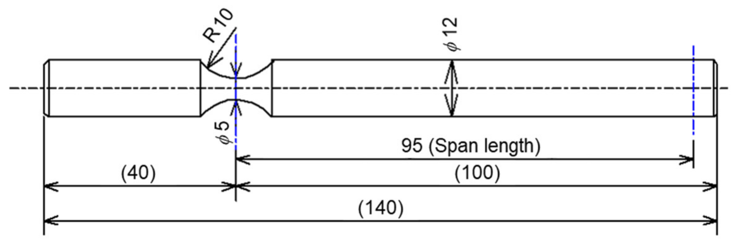
2.1. Sample Preparation

We used A7075-T73 plates with a thickness of 3.175 mm (1/8 inch) to study RSs induced by LPwC. Fatigue samples were prepared by lathing from an A7075BE-T6511 rod with a diameter of 15 mm. The chemical compositions and mechanical properties of both materials are listed in Table 1 and Table 2. The shape and dimensions of the fatigue samples are described in Figure 1. The stress concentration area had a radius of curvature of 10 mm and minimum diameter of 5 mm. The resulting stress concentration factor, Kt, was 1.074.

2.2. LPwC Setup and Conditions

The LPwC setup used to explore RS development in A7075-T73 plates is shown in Figure 2. Laser pulses from a palmtop-sized microchip laser impacted the samples via a plano-convex lens mounted in a coaxial nozzle. Water from the nozzle removed ablation products, thus keeping the laser path clean to prevent absorption or scattering. During laser irradiation, the plate was driven in two dimensions using a linear X–Y stage. We tested two LPwC modes; an underwater mode and a water spray mode (Figure 2, left and right, respectively). The only difference between the modes was the water level. Sakino et al. [33] confirmed that both modes were identical in terms of the ability to create RSs in HT780 high-strength steel. We used both LPwC modes to treat flat A7075-T73 samples and assessed whether the RSs differed.
During LPwC of round rod samples, each sample was placed on a rotating stage and simultaneously driven up or down by a linear stage in the direction of the sample axis; thus, the sample was treated in a spiral manner. A photograph of the setup is shown in Figure 3; we employed the underwater mode to reduce splashing and peening noise.
Table 3 summarizes the laser irradiation conditions. The pulse energy was calculated from the energy at the laser outlet considering energy absorption over the water path of the laser beam. The pulse irradiation density ranged from 100 to 1600 pulse/mm2 for RS evaluation but was fixed at 800 pulse/mm2 for the rod samples. Despite the low pulse energy, the pulse duration was as short as 1.3 ns. Thus, the peak laser power density was quite high, comparable to that of LSP with pulses of a few tens of nanoseconds in duration.
The processing speed can be calculated by dividing the laser pulse repetition rate by the pulse irradiation density. At a pulse repetition rate of 100 Hz and a pulse irradiation density of 800 pulse/mm2, it takes about 13.3 min to process a unit square centimeter.

2.3. Measurement of RSs
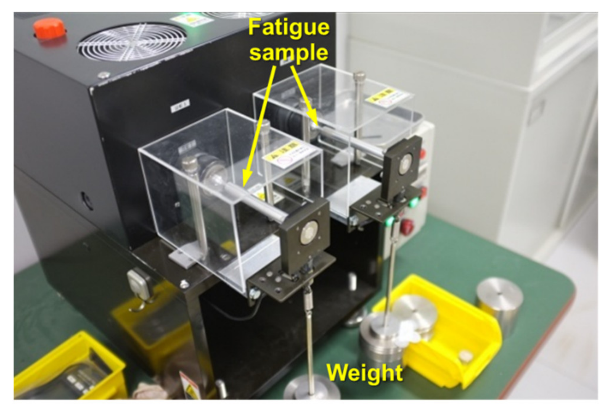
Surface RSs were measured in two directions (X and Y), X is the laser sweep direction and Y is perpendicular to X, using the μ-X360s device (Pulstec Industrial Co. Ltd., Shizuoka, Japan) [34]; this employs the “cosine α” XRD method [35]. The characteristic Cr-kα X-ray was used for irradiation via a collimator of diameter 1.0 mm, and X-rays diffracted by the Al 311 planes were collected by an area detector. The sample was rocked through 10° to obtain a smooth diffraction pattern and reduce the standard deviation of the regression line. The RS depth profiles were estimated via alternating XRD with electrolytic polishing. RS redistribution after removal of a strained area is not large when the removed volume is small. Therefore, the RS values obtained via XRD were not corrected.

2.4. Fatigue

Rotation-bending fatigue was applied to rod samples after LPwC and reference samples without LPwC in ambient conditions; the stress ratio was −1.0, the frequency was 66.7 Hz (4000 rpm), and the run-out was set to 2 × 10⁷ cycles. A cantilever-type fatigue machine was employed (Figure 4).

3. Results and Discussion

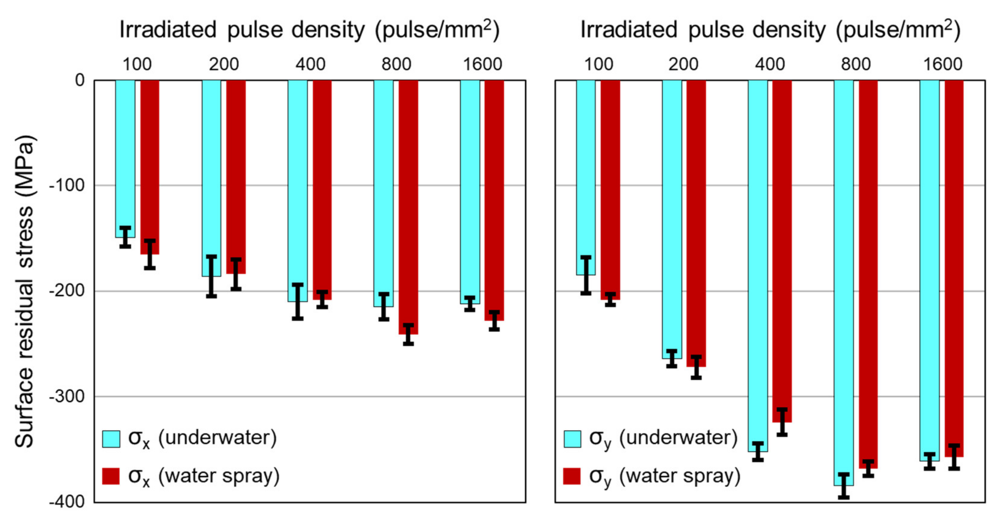
3.1. Surface RSs on A7075-T73

LPwC in both the underwater and water spray modes (Figure 2) was applied to A7075-T73 plates with a thickness of 3.175 mm (1/8 inch). As described in Section 2.2, laser pulses with a wavelength of 1.06 μm, pulse energy of 1.7 mJ, pulse duration of 1.3 ns, and repetition rate of 50 Hz were focused on 0.30-mm-diameter spots. The peak power density (laser fluence) was 1.9 GW/cm2. The irradiated pulse density ranged from 100 to 1600 pulse/mm2.
Figure 5 shows the surface RSs on A7075-T73 plates; σx and σy denote the RS components parallel (X) and perpendicular (Y) to the laser sweep direction, respectively. The standard deviation of the RSs was about ±10 MPa. We confirmed that the absolute value of σy tends to be larger than that of σx, as obtained in our initial study [14]. The RSs afforded by both LPwC modes (underwater and water spray modes) did not differ. The RSs tended to saturate at a pulse density of around 400 pulse/mm2.

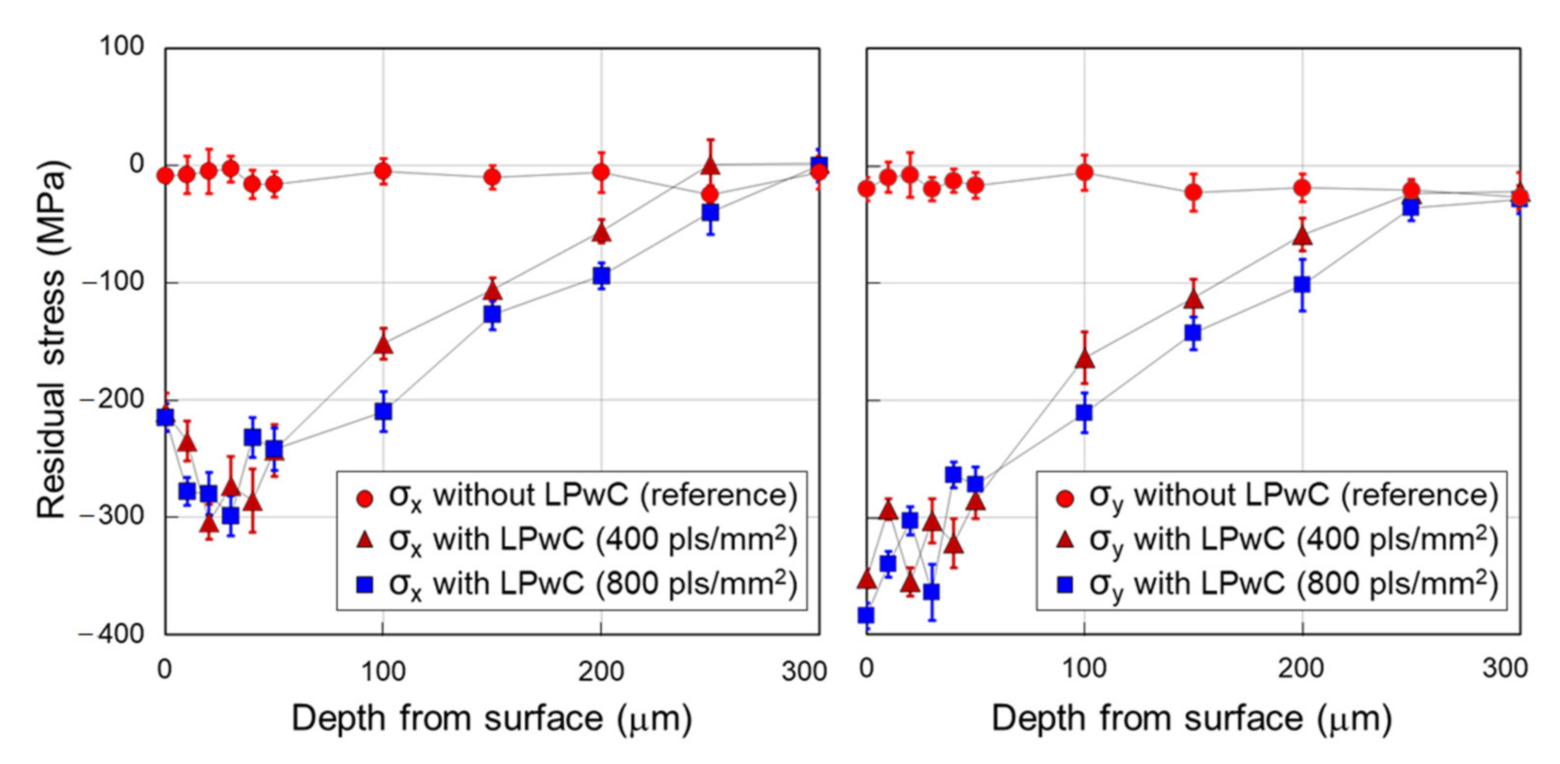
3.2. RS Depth Profiles

The RS depth profiles are depicted in Figure 6 for A7075-T73 subjected and not subjected to LPwC. Compression reached a depth of about 0.25 mm at pulse densities of 400 and 800 pulse/mm2. We expected that the depth would increase as the pulse density increased [6], but this was not the case; probably because the compression induced by LPwC saturated at about 0.25 mm. The maximum compressive RS in the Y-direction was about 400 MPa, which is close to the yield strength (the 0.2% proof stress in Table 2) of the material.
The sample thickness was 3.175 mm, which was much greater than the depth of compression. Therefore, the samples after LPwC have no or only a little distortion. Even if there is some distortion, the RSs will release only slightly and the effects of LPwC would likely be marginally underestimated. Further experiments or simulations might be useful to confirm this.

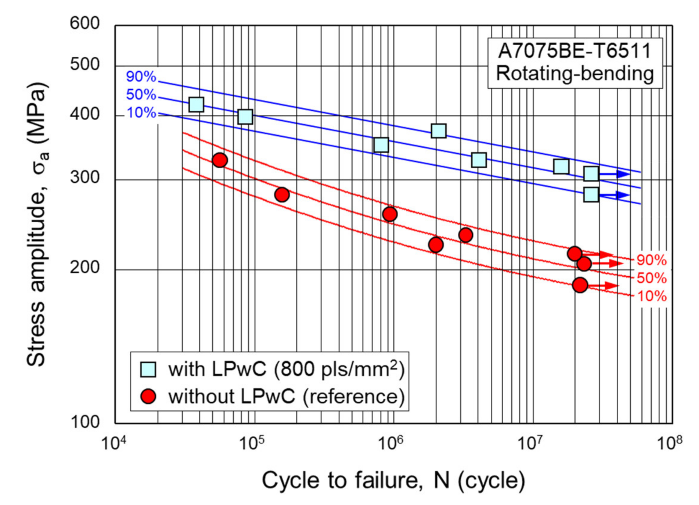
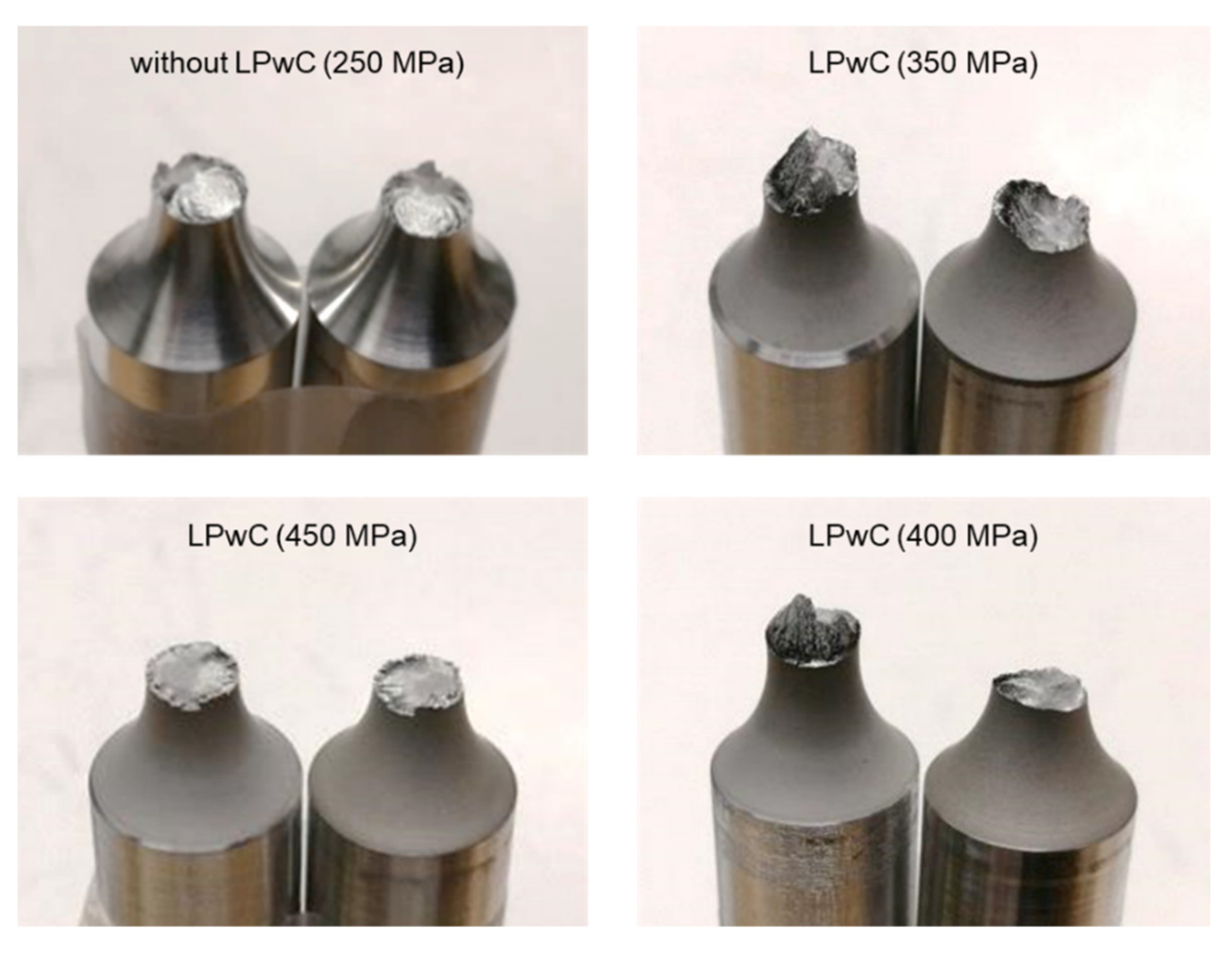
3.3. Fatigue Properties

A7075-T6511 rods were subjected to underwater LPwC (Figure 3). The conditions were the same as for the plate samples, except that the pulse density was fixed at 800 pulse/mm2. Then, rotation-bending fatigue loading was applied to samples that had or had not undergone LPwC using the fatigue machine as shown in Figure 4. The results are summarized in Figure 7 as S–N curves. The data with arrows reached the run-out. The regression curves were obtained using the Strohmeyer’s expression, and the curves for the reference samples and the samples with LPwC are shown in red and blue, respectively. The notation of 10%, 50%, and 90% in the figure are the fracture probabilities predicted by the regression analysis. For the reference samples, the 50% probability of fracture is expressed by
log (σa − 149.2) = −0.1987 log (N) + 3.178
with the sum of squared residuals of 0.00297 and the standard deviation of 0.0273. For the samples with LPwC, it is expressed by
log σa = −0.05113 log (N) + 2.857
with a sum of squared residuals of 0.00285 and a standard deviation of 0.0239.
LPwC at a low pulse energy of 1.7 mJ significantly improved the fatigue characteristics of A7075BE-T6511; the fatigue strength was enhanced about 1.5-fold and the fatigue life about 100-fold. Sakino et al. investigated in detail the effects of LPwC on the fatigue properties of welded joints of 490 MPa grade rolled steel plates and concluded that the main factor in the fatigue properties’ improvement was the compressive RSs introduced into the surface around the weld toe by LPwC [25]. We attempted XRD on A7075BE-T6511 but failed to measure RSs because the material was heavily textured, probably due to fabrication via extrusion. However, the authors expect that LPwC introduced compressive RSs close to the yield strength, as in the case of A7075-T73 (Figure 5 and Figure 6), which resulted in improved fatigue properties.
Figure 8 shows the fracture surfaces of selected samples. The stresses in parentheses are the stress amplitudes applied during the fatigue cycles. In the reference sample without LPwC (250 MPa) and a sample that underwent LPwC (450 MPa), the fracture surfaces are relatively flat and nearly perpendicular to the sample axes. However, LPwC samples at stress amplitudes of 350 and 400 MPa exhibited complicated fracture surfaces with undulations. The original material was extruded and then subjected to tensile pre-straining during stress-relief; the crystal grains would be expected to be strongly oriented and a material textured in this manner may exhibit various fracture surfaces when fatigue loading is combined with the RSs caused by LPwC [36]. When the fatigue loading is sufficiently high, the fatigue crack grows perpendicular to the loading direction, yielding a simple fracture surface. However, if the fatigue loading is smaller than (or competes with) the RSs and effects attributable to the mechanical anisotropy of a textured material, the resulting fracture surface is complicated, reflecting the inherent crystal structure.

4. Conclusions

We subjected A7075-T73 and A7075BE-T6511 aluminum alloys to LPwC at a pulse energy of 1.7 mJ, which is orders of magnitude smaller than the pulse energies of current LSP [1,2,3,4,5] and LPwC [6,14,15,16,17,18] devices. XRD revealed that significant compressive RSs (close to the yield strength) were generated on A7075-T73, and the affected depth was about 0.25 mm from the surface. The rotation-bending fatigue experiments of A7075BE-T6511 showed that LPwC at a pulse energy of 1.7 mJ enhanced the fatigue strength by about 1.5-fold and prolonged the fatigue life by about 100-fold. Thus, even when a palmtop-sized microchip laser was used, LPwC was highly effective, significantly improving the RSs and fatigue properties of A7075 aluminum alloys.
Current LPwC/LSP lasers are bulky and are placed on vibration isolation tables in clean rooms or under ambient temperature control. Their application has therefore been limited to indoor use for production. In contrast, palmtop-sized high-power microchip lasers are portable, extending LPwC applications to various objects not only indoors but also outdoors, such as infrastructure maintenance [6,37,38].

Author Contributions

Conceptualization, Y.S. and K.M.; methodology, K.M. and Y.M.; formal analysis, Y.M. and S.T.; investigation, Y.M. and S.T.; resources, Y.S., T.H. and T.T.; data curation, K.M., Y.M. and S.T.; writing—original draft preparation, Y.S.; writing—review and editing, K.M. and Y.S.; supervision, T.H. and T.T.; project administration, Y.S.; funding acquisition, Y.S., Y.M., T.H. and T.T. All authors have read and agreed to the published version of the manuscript.

Funding

This research was partially supported by the Supporting Industry Program of the Small and Medium Enterprise Agency (grant number: 202041907014), Amada Foundation (grant number: AF-2020239-C2), the Impulsing Paradigm Change through Disruptive Technologies Program (ImPACT) of the Council for Science, Technology and Innovation, and the JST-MIRAI Program (grant number: JPMJMI17A1).

Institutional Review Board Statement

Not applicable.

Informed Consent Statement

Not applicable.

Data Availability Statement

Data presented in this study are available in the article.

Acknowledgments

The authors would like to thank Tomokazu Sano of Osaka University for providing A7075-T73 plates. We also thank Optoquest Co., Ltd. for providing a prototype of a palmtop-sized microchip laser.

Conflicts of Interest

The authors declare no conflict of interest.

References

  1. Clauer, A.H. Laser shock peening, the path to production. Metals 2019, 9, 626. [Google Scholar] [CrossRef] [Green Version]
  2. Ding, K.; Ye, L. Laser Shock Peening; Woodhead Publishing in Materials; Woodhead: Cambridge, UK, 2006. [Google Scholar]
  3. Kruusing, A. Underwater and water-assisted laser processing: Part 1—General features, steam cleaning and shock processing. Opt. Lasers Eng. 2004, 41, 307–327. [Google Scholar] [CrossRef]
  4. Montross, C.S.; Wei, T.; Ye, L.; Clark, G.; Mai, Y.W. Laser shock processing and its effects on microstructure and properties of metal alloys: A review. Int. J. Fatigue 2002, 24, 1021–1036. [Google Scholar] [CrossRef]
  5. Fabbro, R.; Peyre, P.; Berthe, L.; Scherpereel, X. Physics and applications of laser-shock processing. J. Laser Appl. 1998, 10, 265–279. [Google Scholar] [CrossRef]
  6. Sano, Y. Quarter century development of laser peening without coating. Metals 2020, 10, 152. [Google Scholar] [CrossRef] [Green Version]
  7. Altenberger, I.; Nalla, R.K.; Sano, Y.; Wagner, L.; Ritchie, R.O. On the effect of deep-rolling and laser-peening on the stress-controlled low- and high-cycle fatigue behavior of Ti-6Al-4V at elevated temperatures up to 550 °C. Int. J. Fatigue 2012, 44, 292–302. [Google Scholar] [CrossRef]
  8. Spanrad, S.; Tong, J. Characterisation of foreign object damage (FOD) and early fatigue crack growth in laser shock peened Ti-6Al-4V aerofoil specimens. Mater. Sci. Eng. A 2011, 528, 2128–2136. [Google Scholar] [CrossRef]
  9. See, D.W.; Dulaney, J.L.; Clauer, A.H.; Tenaglia, R.D. The air force manufacturing technology laser peening initiative. Surf. Eng. 2002, 18, 32–36. [Google Scholar] [CrossRef]
  10. Curtiss-Wright Surface Technologies. Available online: https://cwst.com/ (accessed on 10 September 2021).
  11. LSP Technologies. Available online: https://www.lsptechnologies.com/ (accessed on 10 September 2021).
  12. Peyre, P.; Berthe, L.; Scherpereel, X.; Fabbro, R. Laser-shock processing of aluminium-coated 55C1 steel in water-confinement regime, characterization and application to high-cycle fatigue behavior. J. Mater. Sci. 1998, 33, 1421–1429. [Google Scholar] [CrossRef]
  13. Peyre, P.; Chaieb, I.; Braham, C. FEM calculation of residual stresses induced by laser shock processing in stainless steels. Model. Simul. Mater. Sci. Eng. 2007, 15, 205–221. [Google Scholar] [CrossRef]
  14. Mukai, N.; Aoki, N.; Obata, M.; Ito, A.; Sano, Y.; Konagai, C. Laser processing for underwater maintenance in nuclear plants. In Proceedings of the 3rd JSME/ASME International Conference on Nuclear Engineering (ICONE-3), Kyoto, Japan, 23–27 April 1995; p. 534. [Google Scholar]
  15. Sano, Y.; Mukai, N.; Okazaki, K.; Obata, M. Residual stress improvement in metal surface by underwater laser irradiation. Nucl. Instrum. Methods Phys. Res. B 1997, 121, 432–436. [Google Scholar] [CrossRef]
  16. Sano, Y.; Kimura, M.; Sato, K.; Obata, M.; Sudo, A.; Hamamoto, Y.; Shima, S.; Ichikawa, Y.; Yamazaki, H.; Naruse, M.; et al. Development and application of laser peening system to prevent stress corrosion cracking of reactor core shroud. In Proceedings of the 8th International Conference on Nuclear Engineering (ICONE-8), Baltimore, MD, USA, 2–6 April 2000. [Google Scholar]
  17. Yoda, M.; Chida, I.; Okada, S.; Ochiai, M.; Sano, Y.; Mukai, N.; Komotori, G.; Saeki, R.; Takagi, T.; Sugihara, M.; et al. Development and application of laser peening system for PWR power plants. In Proceedings of the 14th International Conference on Nuclear Engineering (ICONE-14), Miami, FL, USA, 17–20 July 2006. [Google Scholar]
  18. Sims, W.; Elias, V. Laser peening for long term operation. Nucl. Plant J. 2018, 4, 54–56. [Google Scholar]
  19. Sano, Y.; Akita, K.; Sano, T. A mechanism for inducing compressive residual stresses on a surface by laser peening without coating. Metals 2020, 10, 816. [Google Scholar] [CrossRef]
  20. Sano, Y.; Obata, M.; Kubo, T.; Mukai, N.; Yoda, M.; Masaki, K.; Ochi, Y. Retardation of crack initiation and growth in austenitic stainless steels by laser peening without protective coating. Mater. Sci. Eng. A 2006, 417, 334–340. [Google Scholar] [CrossRef]
  21. Masaki, K.; Ochi, Y.; Matsumura, T.; Ikarashi, T.; Sano, Y. Effects of laser peening treatment on high cycle fatigue and crack propagation behaviors in austenitic stainless steel. J. Power Energy Syst. 2010, 4, 94–104. [Google Scholar] [CrossRef] [Green Version]
  22. Sakino, Y.; Sano, Y.; Kim, Y.-C. Application of laser peening without coating on steel welded joints. Int. J. Struct. Integr. 2011, 2, 332–344. [Google Scholar] [CrossRef]
  23. Sano, Y.; Masaki, K.; Gushi, T.; Sano, T. Improvement in fatigue performance of friction stir welded A6061-T6 aluminum alloy by laser peening without coating. Mater. Des. 2012, 36, 809–814. [Google Scholar] [CrossRef]
  24. Maawad, E.; Sano, Y.; Wagner, L.; Brokmeier, H.-G.; Genzel, C. Investigation of laser shock peening effects on residual stress state and fatigue performance of titanium alloys. Mater. Sci. Eng. A 2012, 536, 82–91. [Google Scholar] [CrossRef]
  25. Sakino, Y.; Sano, Y.; Sumiya, R.; Kim, Y.-C. Major factor causing improvement in fatigue strength of butt welded steel joints after laser peening without coating. Sci. Technol. Weld. Join. 2012, 17, 402–407. [Google Scholar] [CrossRef]
  26. Taira, T. Domain-controlled laser ceramics toward Giant Micro-photonics. Opt. Mater. Express 2011, 1, 1040–1050. [Google Scholar] [CrossRef]
  27. Sato, Y.; Akiyama, J.; Taira, T. Process design of microdomains with quantum mechanics for giant pulse lasers. Sci. Rep. 2017, 7, 10732. [Google Scholar] [CrossRef] [PubMed] [Green Version]
  28. Zheng, L.; Kausas, A.; Taira, T. Drastic thermal effects reduction through distributed face cooling in a high power giant-pulse tiny laser. Opt. Mater. Express 2017, 7, 3214–3221. [Google Scholar] [CrossRef]
  29. Zheng, L.; Kausas, A.; Taira, T. >30 MW peak power from distributed face cooling tiny integrated laser. Opt. Express 2019, 27, 30219–30224. [Google Scholar] [CrossRef] [PubMed]
  30. Unitac Co., Ltd. Available online: https://unitac.net/micro-01/ (accessed on 10 September 2021).
  31. Optoquest Co., Ltd. Available online: https://www.optoquest.co.jp/t-info/?p=280/ (accessed on 10 September 2021).
  32. Optoquest Co., Ltd. Available online: https://www.optoquest.co.jp/t-info/?p=395/ (accessed on 10 September 2021).
  33. Sakino, Y.; Yoshikawa, K.; Sano, Y.; Sumiya, R.; Kim, Y.-C. A basic study for application of laser peening to large-scale steel structure. Q. J. Jpn. Weld. Soc. 2013, 31, 231–237. [Google Scholar] [CrossRef] [Green Version]
  34. Pulstec Industrial Co., Ltd. Available online: https://www.pulstec.co.jp/en/product/x-ray/ (accessed on 10 September 2021).
  35. Tanaka, K. The cos method for X-ray residual stress measurement using two-dimensional detector. Mech. Eng. Rev. 2019, 6, 18-00378. [Google Scholar] [CrossRef] [Green Version]
  36. Sano, Y.; Masaki, K.; Akita, K.; Kajiwara, K.; Sano, T. Effect of laser peening on the mechanical properties of aluminum alloys probed by synchrotron radiation and X-ray free electron laser. Metals 2020, 10, 1490. [Google Scholar] [CrossRef]
  37. Ubiquitous Power Laser for Achieving a Safe, Secure and Longevity Society under ImPACT Program. Available online: https://www.jst.go.jp/impact/sano/index.html/ (accessed on 10 September 2021).
  38. Ubiquitous Power Laser for Achieving a Safe, Secure and Longevity Society under ImPACT Program. Available online: https://www.youtube.com/watch?v=nMsOkkEPK5I/ (accessed on 10 September 2021).
Figure 1. Shape and dimensions of the A7075BE-T6511 fatigue sample.
Metals 11 01716 g001
Figure 2. The LPwC setup for flat samples. Underwater mode (left) and water spray mode (right).
Metals 11 01716 g002
Figure 3. The LPwC setup for rod samples used for rotation-bending fatigue testing.
Metals 11 01716 g003
Figure 4. Rotation-bending fatigue machine.
Metals 11 01716 g004
Figure 5. Surface RSs on A7075-T73 after LPwC (pulse energy 1.7 mJ). Blue and red bars: RSs induced by the underwater and water spray modes, respectively. The RSs in the X- and Y-directions are displayed on the left and right, respectively.
Metals 11 01716 g005
Figure 6. RS depth profiles of A7075-T73 in the X-direction (left) and Y-direction (right).
Metals 11 01716 g006
Figure 7. Fatigue test results of A7075BE-T6511 with and without LPwC.
Metals 11 01716 g007
Figure 8. Fracture surfaces of A7075BE-T6511 samples with and without LPwC.
Metals 11 01716 g008
Table 1. Chemical compositions of the materials used in the experiments (wt%).
MaterialSiFeCuMnMgCrZnTiAl
A7075-T730.070.171.50.022.50.195.70.03Bal.
A7075BE-T65110.080.191.80.042.60.205.80.01Bal.
Table 2. Mechanical properties of the materials used in the experiments.
Material0.2% Proof StressTensile StrengthElongation
A7075-T73425 MPa497 MPa12.0%
A7075BE-T6511627 MPa660 MPa9.2%
Table 3. The LPwC conditions.
ParameterRS SampleFatigue Sample
Laser wavelength (μm)1.061.06
Pulse energy (mJ)1.71.7
Pulse duration (ns)1.31.3
Spot diameter (mm)0.300.30
Peak power density (GW/cm2)1.91.9
Pulse repetition rate (Hz)5050
Pulse density (pulse/mm2)100–1600800
Publisher’s Note: MDPI stays neutral with regard to jurisdictional claims in published maps and institutional affiliations.

