Article

Effect of Laser Shock Peening Parameters on Residual Stresses and Corrosion Fatigue of AA5083

1
HiLASE Centre, Institute of Physics of the Czech Academy of Sciences, 252 41 Dolni Brezany, Czech Republic
2
Faculty of Nuclear Sciences and Physical Engineering, Czech Technical University in Prague, 115 19 Praha, Czech Republic
3
Research Centre Rez, CVR, 301 00 Plzen, Czech Republic
4
Department of Materials Science and Engineering, University of North Texas, Denton, TX 76203, USA
5
Department of Mechanical and Materials Engineering, University of Cincinnati, Cincinnati, OH 45221, USA
*
Author to whom correspondence should be addressed.
Metals 2021, 11(10), 1635; https://doi.org/10.3390/met11101635
Submission received: 17 September 2021 / Revised: 9 October 2021 / Accepted: 9 October 2021 / Published: 14 October 2021
(This article belongs to the Special Issue Laser Peening for Improving Fatigue Properties of Aluminium Alloys)

Abstract

:
Aluminium alloy 5083 was subjected to Laser Shock Peening both with (LSP) and without protective coating (LPwC) at multiple pulse densities. A second LPwC treatment was conducted fully submersed under water, in addition to the standard laminar water flow condition. The results show that compressive residual stresses were generated in all cases, although their character varied depending on the peening strategy and method of confinement. In all cases, higher pulse density lead to an increase in compressive stresses with a saturation point of −325 MPa at 1089 p/cm2 for the LPwC treatments. Corrosion fatigue testing of sensitized samples then showed 59% and 69% improvement in fatigue strength after the LSP and LPwC treatments, respectively.

1. Introduction

Aluminium Alloy 5083 is a strong lightweight material known for its exceptional performance in extreme environments such as seawater, and exposure to industrial chemicals. Due to its excellent corrosion resistance, it is commonly used in the marine industry for the construction of hulls and other ship-related structures [1]. Its characteristic strength is derived from an increased amount of magnesium atoms, which act as obstacles to dislocation movement in the crystal lattice [2]. However, when exposed to elevated temperatures (>50 °C) the alloy undergoes a process known as sensitization [1,3,4] and becomes susceptible to intergranular corrosion (IGC) [5,6,7]. External stresses represented by static or cyclic structural loading during the ship operation can then, in combination with IGC, lead to intergranular stress corrosion cracking (IGSCC) or corrosion fatigue (CF). While significant attention has been paid to investigating IGSCC behaviour [8,9], only a limited number of studies have investigated the effects of CF on AA5083 in aggressive marine environments [10,11,12], where fatigue loading is introduced by wind and wave motion, ship machinery vibrations, thermal expansion, and contraction and operational loading events [13,14].
In this paper, we focus on improving CF resistance of AA5083 through the generation of beneficial compressive residual stresses by means of Laser Shock Peening (LSP). This has already been shown to positively influence corrosion behaviour of other metallic alloys [15,16,17,18]. In the typical LSP setup, a protective overlay or coating, in the form of vinyl or aluminium tape, is used to protect the sample surface from heat effects that occur during laser absorption and can generate tensile stresses. A laminar flow of water across the surface is used as a means of pressure confinement. However, application of the tape underwater is not possible. Therefore, the effects of LSP without the protective coating (LPwC) were also investigated, following the works of Sano et al. [19,20], including fully submersed underwater peening, to facilitate its possible application in real marine environments.

2. Materials and Methods

2.1. Material

For the residual stress (RS) measurements, a 6.35 mm thick plate of AA5083-H116 was sectioned using electric discharge machining into 40 mm × 40 mm square coupons and polished to 600 grit with silicon carbide paper. The chemical composition of the alloys is shown in Table 1. The coupons were peened, in their received condition, without any additional heat treatment.
The corrosion fatigue samples were in the form of 60 mm × 12 mm × 4 mm blocks sectioned from a 25.4 mm thick rolled plate. The samples were polished to 600 grit and then were sensitized at 100 °C for 60 days prior to the LSP treatment and subsequent corrosion fatigue (CF) testing. The sensitized material was determined to be IGC susceptible following the ASTM G67 standard [21] where the degree of sensitization (DoS) was determined to be 5 mg/cm2 and 44.6 mg/cm2 for the as-received material and the sensitized material, respectively.

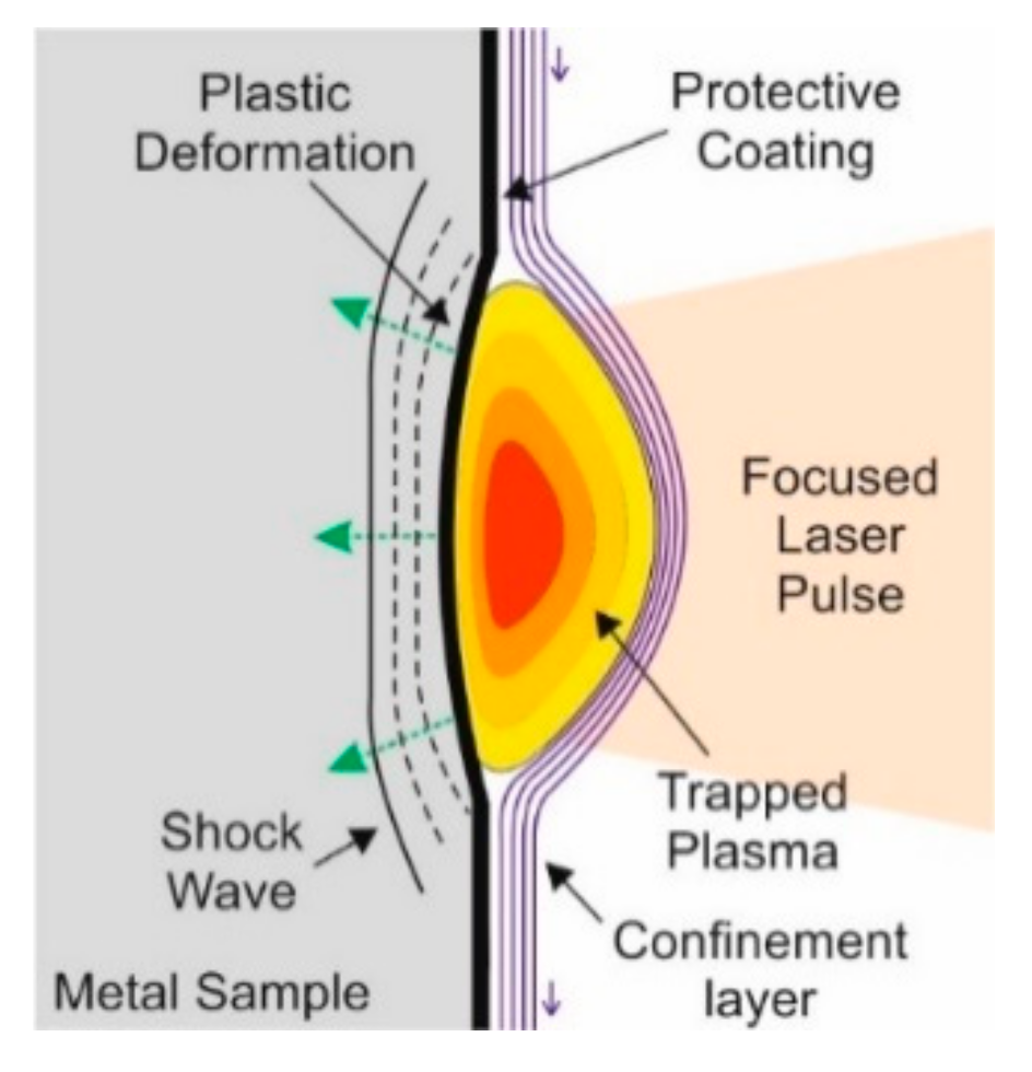
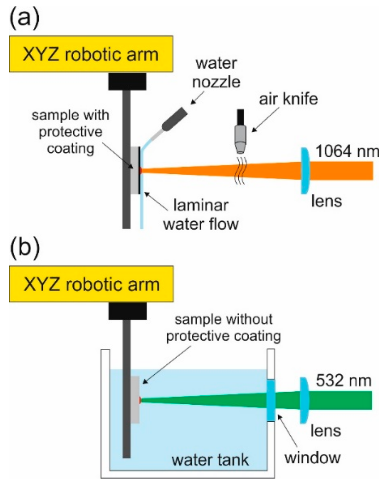
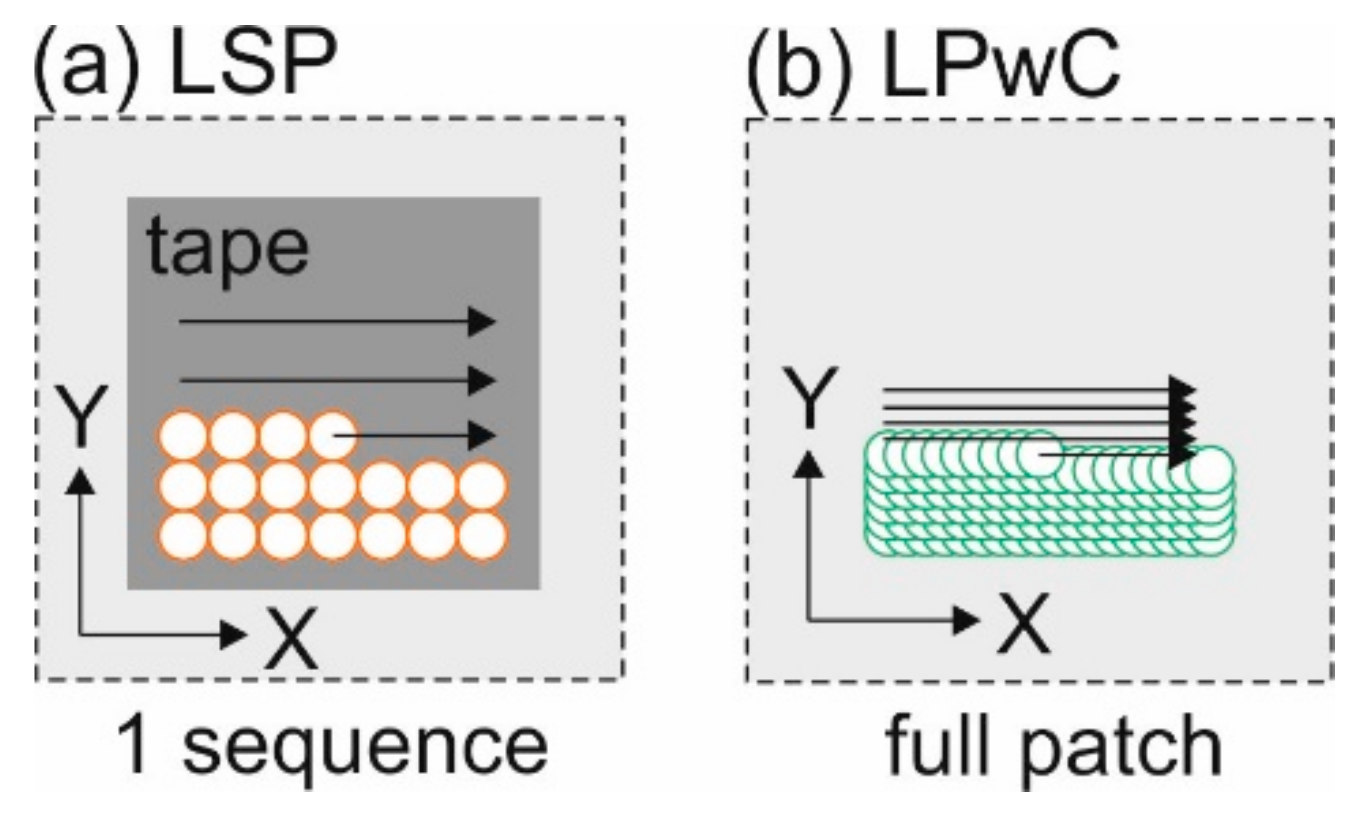
2.2. Laser Shock Peening with and without Coating

The LSP process uses high-energy nanosecond laser pulses to generate deep compressive residual stresses in metallic materials. The sample surface is usually covered with a protective coating in the form of black vinyl tape or paint, which absorbs the focused laser pulses (Figure 1). The subsequent rapidly expanding plasma is confined against the sample surface by a thin water layer (1–2 mm thick), and a strong shock wave with a magnitude of several GPa [22], is formed. If the pressure exceeds the yield strength of the material, the surface is plastically deformed and compressive stresses are generated. With the protective coating applied, LSP can be considered a cold working process since the heat associated with the laser absorption is screened from the sample surface and only plastic deformation takes place. In Laser Peening without Coating (LPwC), the surface is directly affected by heat, which can substantially affect the residual stresses in the near surface layer.
In this study, three basic peening setups were investigated–one with coating (LSP) and two without coating (LPwC). In all three cases, the peening was applied using a Powerlite Plus Nd:YAG laser system (Powerlie DLS Plus, Continuum, Milpitas, CA, USA) operating at 1064 nm with 10 Hz repetition rate with an option to switch to 532 nm using second harmonic generation (SHG). The sliced pulses [23] were 22 ns in duration (FWHM) and had a circular top-hat beam profile. The first setup utilized protective coating in the form of a 100 μm black vinyl tape and a laminar film (~1 mm) of flowing water, while using the 1064 nm infrared (IR) laser wavelength (LSP IR)(Continuum, Milpitas, CA, USA). The setup is depicted in Figure 2a. Pulses of 3 J were focused to a 2.6 mm circular laser spot with a resulting power density of 2.6 GW/cm2. The peening was delivered in the form of layers, each consisting of 4 sequences with the tape replaced between each sequence. The laser spot overlap within one sequence was 0% and the sequences were shifted with respect to the first sequence by half the spot size in X, Y, and XY directions, consecutively, so that a uniform 50% overlap was achieved eventually. The peening strategy for one sequence is show in Figure 3a. Both cases, with 1 layer (LSP IR 1L) and 2 layers applied (LSP IR 2L), were investigated. For the CF samples, only the LSP IR 2L condition was applied. The treated area for all the RS and CF samples was 20 mm × 20 mm and 10 mm × 12 mm, respectively. Furthermore, all CF samples were treated on both sides to prevent bending, and the laser scanning was perpendicular to the long edge of the sample. The LSP IR samples after peening, both RS and CF, are shown in Figure 4a. Plastic deformation in the treated area can be clearly observed while the surface remains heat unaffected.
The second peening setup was the same as in Figure 2a. The IR wavelength was used, but the protective coating was removed (LPwC IR). With the tape absent, the patch was peened in a single pass using overlapping laser pulses (Figure 3b) with varied pulse density, specifically 204, 400, 1089 and 2500 p/cm2. The pulse energy was 1 J with a laser spot size of 1.5 mm. The power density was again 2.6 GW/cm2. The CF samples were peened with 1089 p/cm2. The samples after peening are shown in Figure 4b. The thermally affected area now shows a distinct look after the melting during the laser pulse absorption
The third setup also involved peening without coating, but the samples were treated under water in a water tank (Figure 2b). In this case, the second harmonic of the laser at 532 nm was used (LPwC SHG) (Continuum, Milpitas, CA, USA) due to attenuation of the IR wavelength in water. The pulse energy was once again 1 J with laser spot size of 1.5 mm, power density of 2.6 GW/cm2 and varied pulse density of 204, 400, 1089 and 2500 p/cm2. The CF samples were peened with 1089 p/cm2. The LPwC SHG samples are shown in Figure 4c with the melted area clearly visible.

2.3. Residual Stress and 3-Point Bend Testing

The stress measurements were conducted on an X-ray diffractometer (XRD) (Proto, Taylor, MI, USA) Proto LXRD instrument using the sin2ψ method using Cr Kα (2.2897 nm) radiation at 2ϴ = 139°. The stresses were measured in two perpendicular directions, scanning (σS) and transversal (σT) with respect to the laser peening scanning, and advancing directions, respectively. To measure residual stresses through depth, layers of the material were progressively removed using an electro polisher with 87.5:12.5 vol% CH3OH:H2SO4 electrolytic solution. The thickness of material removed was measured with a precise micrometre. Smaller measurement steps were taken close to the material surface and strain, and depth corrections were applied using the evaluation software.
Corrosion fatigue tests were performed on Electromagnetic pulsator Testronic (Rumul, Neuhausen am Rheinfall, Switzerland) for high cycle fatigue testing. The 3-point bend test was load controlled and took place at room temperature at 45 Hz with R value 0.1. The supports were 20 mm apart and the specimen was submerged in 3.5% NaCl solution. The LSP treated face corresponded to the TS plane of the original plate with the loading being in the long-transverse direction. The terminating condition was either when 107 cycles were reached, or when the frequency dropped by 20 Hz due to lowered toughness, signified by a crack that developed and started to propagate. The testing setup is shown in Figure 5.

3. Results and Discussion

3.1. Residual Stresses

Figure 6 shows in-depth residual stress measurement results in all three peening setups. Multiple pulse densities are investigated for LPwC as well as number of layers in the LSP treatment. Additionally, the data measured is compared to the baseline material, i.e., material where no laser peening was applied. The standard deviation of any of the XRD measurements did not exceed ± 18 MPa. The LSP IR condition is represented on the top row of Figure 6. The left and right columns show stresses measured in the scanning and transversal directions, respectively. In comparison with the baseline, the LSP treatment with protective tape, clearly generates significant compressive residual stresses, around −200 MPa on the surface, and maximum compressive stresses reached at a depth of about 200 µm. More laser pulse impacts represented by the 2L plot cause a constant increase of about 50 MPa in the compressive stresses. The stresses induced in both σS and σT directions are very similar and no significant variations are observed. The compression depth in both directions is about 1.5–1.6 mm, which is higher than in the LPwC cases. This can be explained by the use of a larger spot size as, according to the literature, shock waves generated by laser impacts with larger spot size attenuate slower and thus deeper residual stresses are produced [24,25]. The middle row graphs in Figure 6 represent the LPwC IR condition. Unlike the LSP IR plots, there is a clear distinction between σS and σT. In scanning direction, the residual stresses peak almost immediately at a pulse density as low as 204 p/cm2. The maximum compressive stress reached is −150 MPa and the compression depth is about 1.5 mm regardless of the pulse density. In the transversal direction, the stress curve changes as higher pulse densities are applied. A maximum compression of about −325 MPa was achieved corresponding to pulse density of 1089 p/cm2. The ultimate tensile strength of the material is 317 MPa which means a saturation point was reached. The compression depth reached was in the range of 1.2 mm to 1.4 mm with the highest depth corresponding to 204 p/cm2 and lowest to 2500 p/cm2. The stress plots for the LPwC SHG condition are displayed at the bottom row of Figure 6. The results are similar to the LPwC IR case, showing the same distinction between the σS and σT measurements. The maximum compressive stresses reached in the scanning direction were about −180 MPa with very fast saturation. The compression depth ranged between 1.1 mm and 1.4 mm. The σT measurements show the same trends as their LPwC IR counterpart with saturation reached at −325 MPa at 1089 p/cm2. The plots show, however, that the saturation point is reached faster in the LPwC IR case which is evident from the higher stress values of the 204 p/cm2 and 400 p/cm2 plots. The peaks in the LPwC SHG case are also sharper and the subsequent drop-off is faster. The depths reached are once again between 1.1 mm and 1.4 mm depending on the pulse density. Similar resultant stress anisotropy with LPwC treatment was observed in other studies [26,27,28,29,30,31]. Correa et al. [31] explain the phenomenon in the context of interacting stress fields created by laser pulses overlapping in zigzag scanning patterns. As a result, the residual stresses are higher in the advancing transversal direction as opposed to the scanning direction. Furthermore, the stress anisotropy only occurs when the pulse overlap occurs within one laser pass. This is evidenced here in the top row of Figure 6 where despite the final overlap being 50% in the LSP IR case, the overlap within each separate sequence was 0% and as a result, no residual stress anisotropy was detected. On the contrary, high stress anisotropy was found in both LPwC IR and LPwC SHG where high laser pulse overlap was achieved within a single laser pass.
Special attention is paid to the surface residual stresses where, based on the literature [32], the biggest difference between the treatment with and without tape should be found. With the LSP IR treatment involving protective tape the surface stresses are rather straightforward, about −175 MPa for 1L and −200 MPa for 2L in both directions. Without the tape, the results start to vary based on the environment. The surface stress values for LPwC IR and LPwC SHG are separately plotted against pulse density in Figure 7. The LPwC IR data in Figure 7a shows that despite the heat effects present in the treatment, the stresses moved towards compression both in σS and σT measurements when compared to the baseline. The stresses peak rather fast around 400 p/cm2 and then level off. The difference between σS and σT is about 60–80 MPa and is kept constant over the whole data range. The surface stress measurement in LPwC SHG (Figure 7b) shows a similar trend, but everything is shifted in the tensile direction. The underwater peening at the lowest pulse density causes an abrupt shift of roughly 150 MPa towards tensile stresses in both scanning and transversal direction, creating tensile residual stresses of 105 MPa and 37 MPa as opposed to baseline values of −55 MPa and −109 MPa, respectively. The stresses then start to move toward compression as the pulse density rises. Compared to the LPwC IR data, however, it does not level off and keeps dropping at a low rate within the data range. While the initial baseline value in σT is regained at 2500 p/cm2, the data suggests that the baseline value will not be reached in the σS plot. As the laser energy should be absorbed readily, regardless of wavelength by the plasma layer that forms near instantaneously compared to the nanosecond scale pulse duration, the difference in laser wavelengths is expected to be largely inconsequential, assuming that energy delivered per pulse remains constant. The differences between the LPwC IR and LPwC SHG conditions are therefore more likely to arise from changes in the confinement and resulting interactions between the plasma and the metal surface. Further analysis, however, is required and is currently beyond the scope of this study. Sano and other authors suggest that compressive residual surface stresses can be achieved under water when lower pulse energies (<250 mJ) with very high pulse densities (~10000 p/cm2) are used [15,19,33].

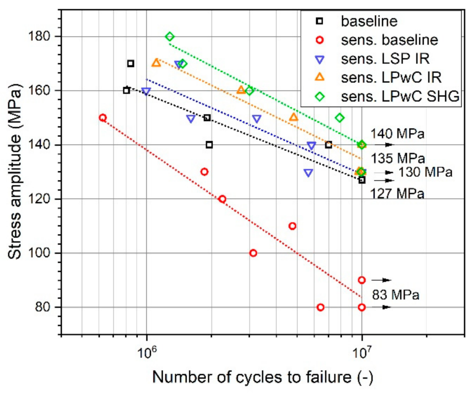
3.2. Corrosion Fatigue

Based on the residual stress measurements, the best performing conditions for each peening setup were selected for the CF testing. These were the LSP IR 2L where higher compression was measured and LPwC IR 1089 p/cm2 and LPwC SHG 1089 p/cm2 where saturation in compressive stresses was reached. The results of the 3-point bend test are shown in Figure 8. Data points with arrows mark samples that did not break during the test and were halted after 107 cycles. The baseline material that was not treated by laser peening, without and with sensitization, is represented by the black and red plots, respectively. The sensitized sample displays the S–N curve shifted down which shows a clear negative effect of IGC on the CF of AA5083. The fatigue strength at 107 cycles of the non-sensitized baseline material was 127 MPa which is 44 MPa higher than the sensitized baseline sample. Both the LSP and LPwC treatments had a positive impact on the fatigue, bringing the S–N curves back up and possibly improving the original non-sensitized fatigue strength. Better improvements were achieved with the LPwC IR and LPwC SHG treatments where the fatigue strength improved by 63% and 69%, respectively. The LSP IR showed the least improvement out of the treatments tested, but still reached a slightly higher fatigue resistance than the non-sensitized sample. Fatigue strength improved by 59% when compared to the control sensitized samples. However, due to relatively low amount of samples tested for each condition, this detailed comparison should be regarded with caution.
SEM images of cracked samples are shown in Figure 9. In all cases, the fatigue crack was initiated in the central part of the loaded section, specifically at one of the sample edges, and the crack propagation was perpendicular to the tensile loading vector. The crack propagation mechanism of transgranular cracking was the same for all tested conditions, which can be observed in the bottom part of Figure 9. The highest corrosion damage was observed on the fracture plane of the sensitized baseline sample (Figure 9b) with pitting as the dominant corrosion mechanism. Laser peened samples showed significantly lower pitting damage.
The CF improvement is attributed to the compressive residual stresses imparted by the LSP and LPwC treatments. Higher fatigue life of the LPwC samples could be explained by the residual stress anisotropy. The LPwC fatigue samples had the transversal axis oriented parallel to the stress loading, which means higher compression was achieved. Other authors also report positive impact of the enhanced oxide layer created during the LPwC process, which improved corrosion resistance of various aluminium alloys [34,35].

4. Conclusions

Laser shock peening with (LSP) and without (LPwC) protective coating was applied to 5083-H116 aluminium alloy to investigate its effect on residual stresses and corrosion fatigue. The following conclusions can be made:
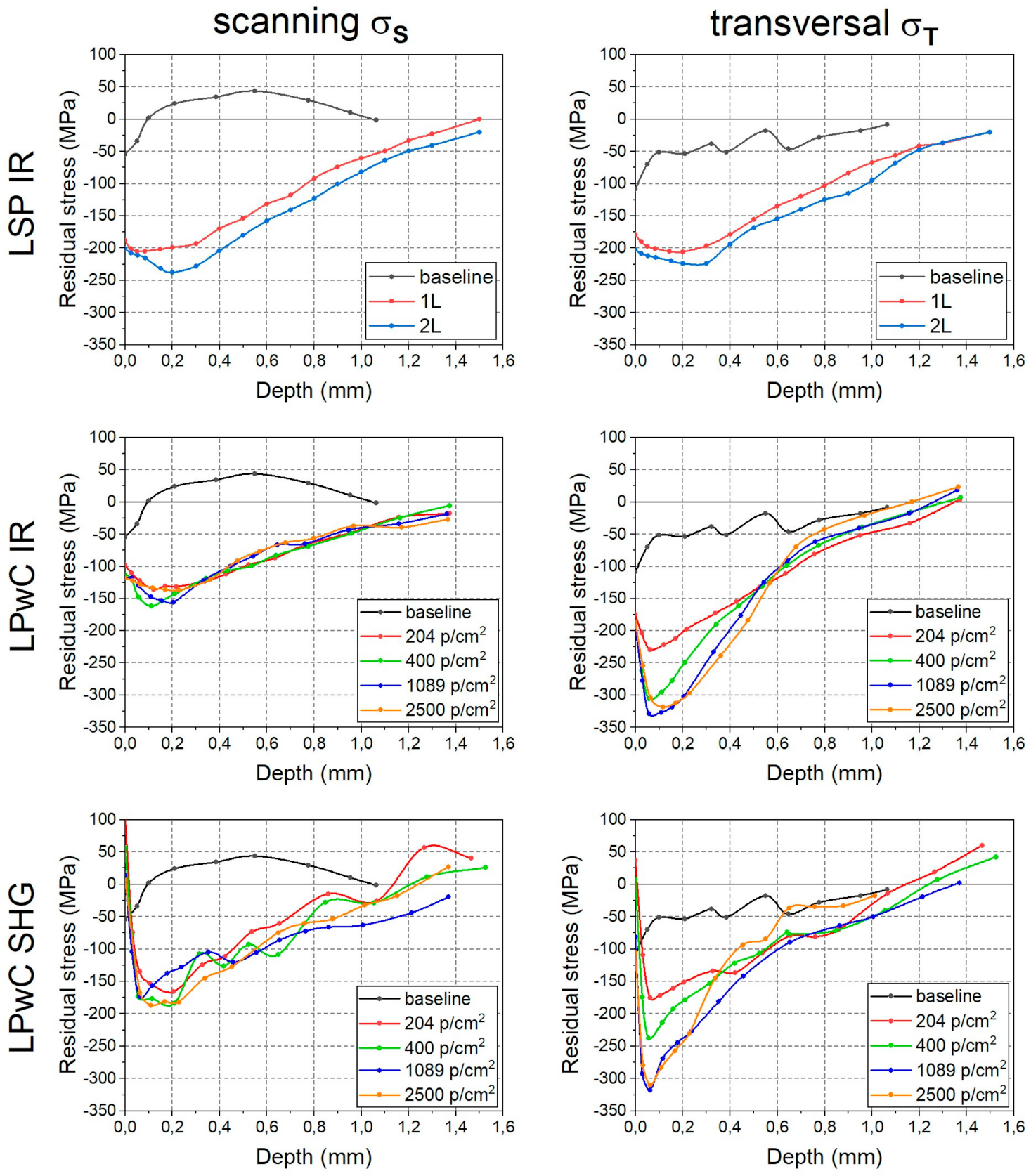
  • Both LSP and LPwC imparts deep compressive residual stresses into the studied material. The magnitude of the stresses rises with the number of laser pulse impacts until a saturation point is reached. Slightly deeper stresses were obtained with LSP treatment where larger spot size was used.
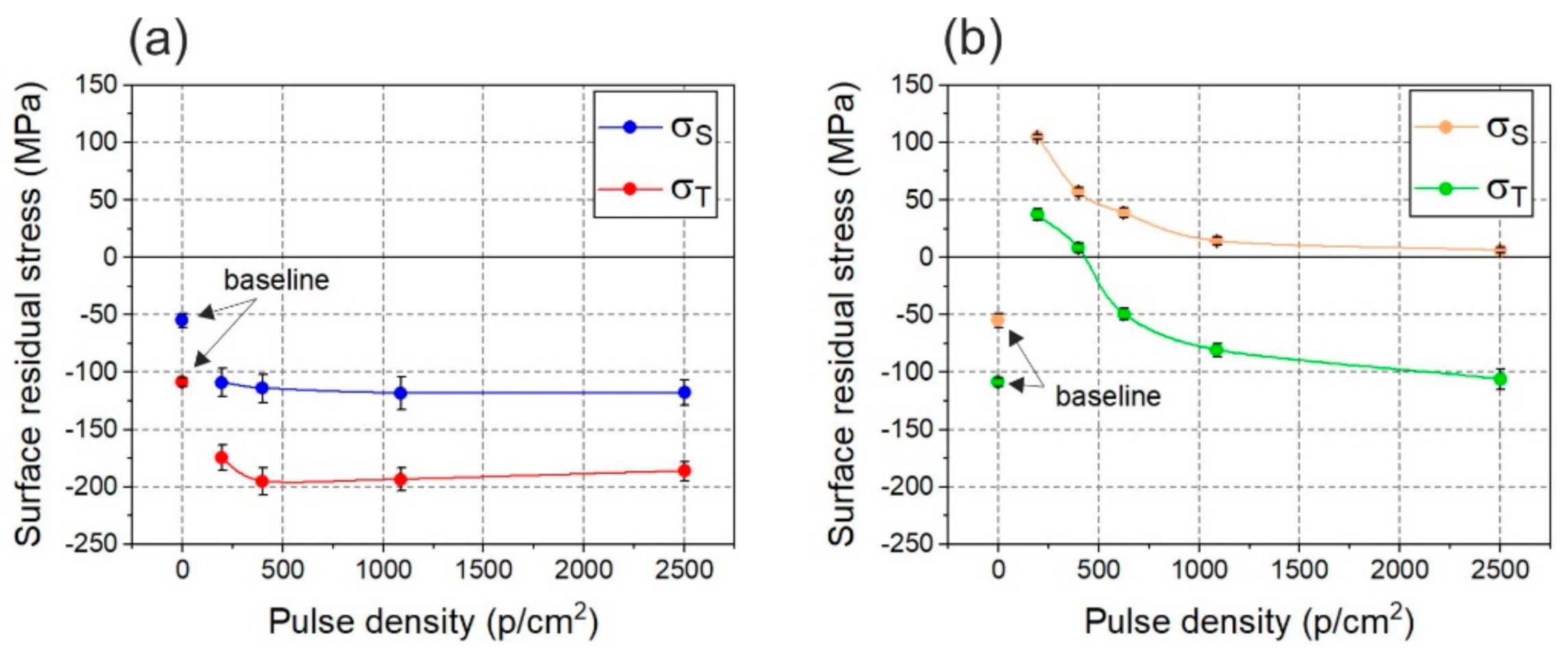
  • Residual stress anisotropy was observed in cases of LPwC treatments, where larger compressive stresses up to a point of material saturation, were measured in the laser advancing direction with respect to the peening pattern. The anisotropy is explained by stress field interaction during pulse overlapping, and is completely absent in the LSP case, where 0% pulse overlap within individual sequences was used.
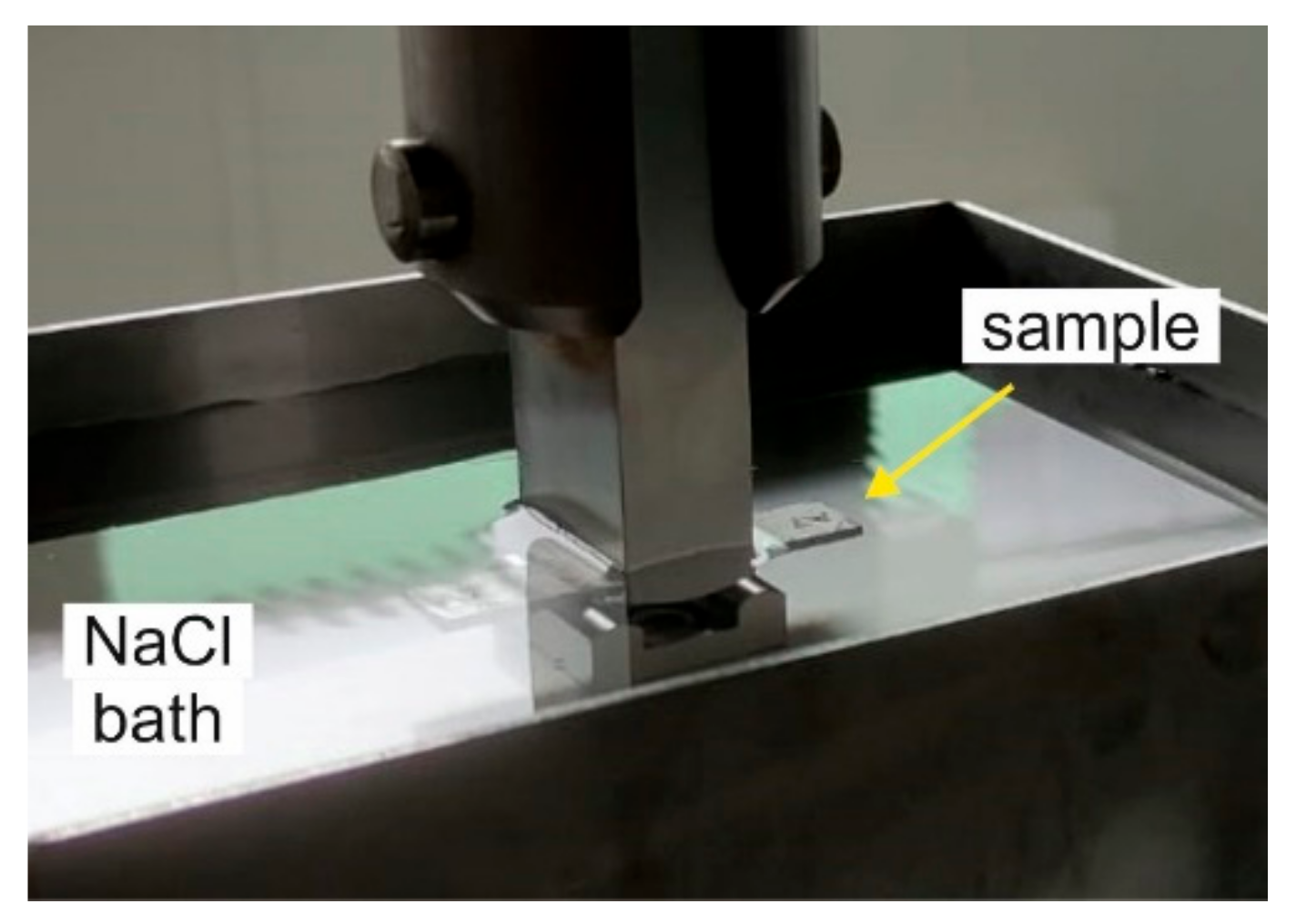
  • Comparable compressive residual stresses were found on surface of both LSP and LPwC conditions with thin water film confinement. In both cases, the surface stress magnitude was mostly independent on the number of laser impacts. In cases where LPwC was performed under water, tensile surface stresses were measured which turned into compressive in the transversal direction for higher pulse densities.
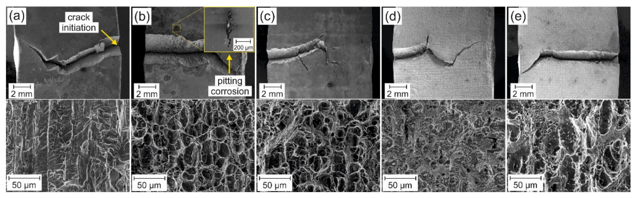
  • Sensitization has a negative impact on corrosion fatigue of the material which manifests as a 35% drop in fatigue strength. LSP and LPwC treatment restored and even possibly improved the original fatigue resistance of the non-sensitized samples. The improvement over the sensitized material appears to be over 60%, especially with the LPwC underwater treatment, although more data points would be required for higher statistical certainty.
This study demonstrates that LSP can reliably generate deep compressive residual stresses in the magnesium enhanced aluminium alloy, both with and without protective coating, which leads to significant improvement in corrosion fatigue.

Author Contributions

Conceptualization, J.K., V.K.V. and M.A.S.; methodology, J.K., Z.Š. and S.R.M.; validation, Z.Š., M.A.S. and V.K.V.; formal analysis, J.K. and Z.Š.; investigation, J.K. and S.R.M.; resources, S.R.M., J.B., T.M.; data curation, J.K.; writing—J.K.; writing—review and editing, V.K.V. and M.A.S.; visualization, J.K.; supervision, S.R.M., J.B. and L.P.; project administration, T.M. and V.K.V.; funding acquisition, S.R.M., V.K.V. and T.M. All authors have read and agreed to the published version of the manuscript.

Funding

This research was funded by European Structural and Investing Funds, Operational Programme Research, Development and Education (Grant number CZ.02.1.01/0.0/0.0/15_006/ 0000674) and from the European Union’s Horizon 2020 research and innovation programme (Grant number 739573. J.K., M.A.S., S.R.M. and V.K.V. would also like to express our gratitude to the Ohio Department of Development and Third Frontier Commission (Grant number TECH 10-014), which provided funding in support of the “Ohio Center for Laser Shock Processing for Advanced Materials and Devices” and the equipment in the center that was used in the initial part of this work. Additional thanks are directed to CVR—Research centre Rez where part of the testing took place.

Institutional Review Board Statement

Not applicable.

Informed Consent Statement

Not applicable.

Data Availability Statement

The data presented in this study are available on request from the corresponding author. The data are not publicly available due to time constraints.

Conflicts of Interest

The authors declare no conflict of interest. The funders had no role in the design of the study; in the collection, analyses, or interpretation of data; in the writing of the manuscript, or in the decision to publish the results.

References

  1. Golumbfskie, W.J.; Tran, K.T.; Noland, J.M.; Park, R.; Stiles, D.J.; Grogan, G.; Wong, C. Survey of detection, mitigation, and repair technologies to address problems caused by sensitization of Al-Mg alloys on navy ships. Corrosion 2016, 72, 314–328. [Google Scholar] [CrossRef]
  2. Huskins, E.L.; Cao, B.; Ramesh, K.T. Strengthening mechanisms in an Al-Mg alloy. Mater. Sci. Eng. A 2010, 527, 1292–1298. [Google Scholar] [CrossRef]
  3. Bovard, F.S. Sensitization and environmental cracking of 5xxx aluminum marine sheet and plate alloys. In Corrosion in Marine and Saltwater Environments II: Proceedings of the International Symposium; The Electrochemical Society: Pennington, NJ, USA, 2005; pp. 232–243. [Google Scholar]
  4. Holtz, R.L.; Goswami, R.; Pao, P.S. Sensitization of Naturally Aged Aluminum 5083 Armor Plate; Naval Research Lab: Washington, DC, USA, 2015. [Google Scholar]
  5. Zhang, R.; Knight, S.P.; Holtz, R.L.; Goswami, R.; Davies, C.H.J.; Birbilis, N. A survey of sensitization in 5xxx series aluminum alloys. Corrosion 2016, 72, 144–159. [Google Scholar] [CrossRef]
  6. Lim, M.L.C.; Kelly, R.G.; Scully, J.R. Overview of intergranular corrosion mechanisms, phenomenological observations, and modeling of AA5083. Corrosion 2016, 72, 198–220. [Google Scholar] [CrossRef]
  7. Sridharan, K.; Allen, T.R.; Yang, Y.K.; Maier, B.R.; Hauch, B.J. Mitigation of Corrosion in 5xxx Series Al-Mg Alloys in Marine Environments: Grain Boundary Engineering and Cold Spray Coating Approaches; Defencee Technical Intionation Center: Fort Belvoir, WV, USA, 2014. [Google Scholar]
  8. Crane, C.B.; Gangloff, R.P. Stress corrosion cracking of Al-Mg alloy 5083 sensitized at low temperature. Corrosion 2016, 72, 221–241. [Google Scholar] [CrossRef]
  9. Searles, J.L.; Gouma, P.I.; Buchheit, R.G. Stress corrosion cracking of sensitized AA5083 (Al-4.5 Mg-1.0 Mn). Metall. Mater. Trans. A 2001, 32, 2859–2867. [Google Scholar] [CrossRef]
  10. Abdulstaar, M.; Mhaede, M.; Wollmann, M.; Wagner, L. Investigating the effects of bulk and surface severe plastic deformation on the fatigue, corrosion behaviour and corrosion fatigue of AA5083. Surf. Coat. Technol. 2014, 254, 244–251. [Google Scholar] [CrossRef]
  11. Holtz, R.L.; Pao, P.S.; Bayles, R.A.; Longazel, T.M.; Goswami, R. Corrosion fatigue of Al 5083-H131 sensitized at 70, 100, and 175 C relation to microstructure and degree of sensitization. In DoD Corrosion Conference; NACE/DoD: Houston, TX, USA, 2011. [Google Scholar]
  12. Benedictus-deVries, S.; Bakker, A.; Janssen, G.C.A.M.; de Wit, H. Fatigue crack initiation behavior of welded AA5083 in a seawater environment. J. Eng. Mater. Technol. 2004, 126, 199–203. [Google Scholar] [CrossRef]
  13. Wirsching, P.H.; Chen, Y.-N. Considerations of probability-based fatigue design for marine structures. Mar. Struct. 1988, 1, 23–45. [Google Scholar] [CrossRef] [Green Version]
  14. Cui, W. A state-of-the-art review on fatigue life prediction methods for metal structures. J. Mar. Sci. Technol. 2002, 7, 43–56. [Google Scholar] [CrossRef]
  15. Sano, Y.; Obata, M.; Kubo, T.; Mukai, N.; Yoda, M.; Masaki, K.; Ochi, Y. Retardation of crack initiation and growth in austenitic stainless steels by laser peening without protective coating. Mater. Sci. Eng. A 2006, 417, 334–340. [Google Scholar] [CrossRef]
  16. Peyre, P.; Berthe, L.; Fabbro, R.; Braham, C.; Lédion, J. Corrosion reactivity of laser-peened steel surfaces. J. Mater. Eng. Perform. 2000, 9, 656–662. [Google Scholar] [CrossRef]
  17. Wang, J.T.; Zhang, Y.K.; Chen, J.F.; Zhou, J.Y.; Ge, M.Z.; Lu, Y.L.; Li, X.L. Effects of laser shock peening on stress corrosion behavior of 7075 aluminum alloy laser welded joints. Mater. Sci. Eng. A 2015, 647, 7–14. [Google Scholar] [CrossRef]
  18. Zhang, Y.; You, J.; Lu, J.; Cui, C.; Jiang, Y.; Ren, X. Effects of laser shock processing on stress corrosion cracking susceptibility of AZ31B magnesium alloy. Surf. Coat. Technol. 2010, 204, 3947–3953. [Google Scholar] [CrossRef]
  19. Sano, Y.; Akita, K.; Masaki, K.; Ochi, Y.; Altenberger, I.; Scholtes, B. Laser peening without coating as a surface enhancement technology. Pulse 2006, 100, 250mJ. [Google Scholar] [CrossRef] [Green Version]
  20. Sano, Y.; Masaki, K.; Gushi, T.; Sano, T. Improvement in fatigue performance of friction stir welded A6061-T6 aluminum alloy by laser peening without coating. Mater. Des. (1980–2015) 2012, 36, 809–814. [Google Scholar] [CrossRef]
  21. American Society for Testing and Materials. Standard Test Method for Determining the Susceptibility to Intergranular Corrosion of 5XXX Series Aluminum Alloys by Mass Loss after Exposure to Nitric Acid (NAMLT Test); ASTM Int: West Conshohocken, PA, USA, 2004. [Google Scholar]
  22. Fabbro, R.; Peyre, P.; Berthe, L.; Scherpereel, X. Physics and applications of laser-shock processing. J. Laser Appl. 1998, 10, 265–279. [Google Scholar] [CrossRef]
  23. Sollier, A.; Berthe, L.; Peyre, P.; Bartnicki, E.; Fabbro, R. Laser-matter interaction in laser shock processing. In First International Symposium on High-Power Laser Macroprocessing; International Society for Optics and Photonics: Bellingham, WA, USA, 2003; Volume 4831, pp. 463–467. [Google Scholar] [CrossRef]
  24. Warren, A.W.; Guo, Y.B.; Chen, S.C. Massive parallel laser shock peening: Simulation, analysis, and validation. Int. J. Fatigue 2008, 30, 188–197. [Google Scholar] [CrossRef]
  25. Kalentics, N.; Boillat, E.; Peyre, P.; Ćirić-Kostić, S.; Bogojević, N.; Logé, R.E. Tailoring residual stress profile of selective laser melted parts by laser shock peening. Addit. Manuf. 2017, 16, 90–97. [Google Scholar] [CrossRef] [Green Version]
  26. Hirano, K.; Sugihashi, A.; Imai, H.; Hamada, N. Mechanism of anisotropic stress generation in laser peening process. Int. Congr. Appl. Lasers Electro-Opt. 2006, 2006, P511. [Google Scholar] [CrossRef]
  27. Hfaiedh, N.; Peyre, P.; Song, H.; Popa, I.; Ji, V.; Vignal, V. Finite element analysis of laser shock peening of 2050-T8 aluminum alloy. Int. J. Fatigue 2015, 70, 480–489. [Google Scholar] [CrossRef] [Green Version]
  28. Peyre, P.; Hfaiedh, N.; Song, H.; Ji, V.; Vignal, V.; Seiler, W.; Branly, S. Laser shock processing with two different laser sources on 2050-T8 aluminum alloy. Int. J. Struct. Integr. 2011. [Google Scholar] [CrossRef]
  29. Dorman, M.; Toparli, M.B.; Smyth, N.; Cini, A.; Fitzpatrick, M.E.; Irving, P.E. Effect of laser shock peening on residual stress and fatigue life of clad 2024 aluminium sheet containing scribe defects. Mater. Sci. Eng. A 2012, 548, 142–151. [Google Scholar] [CrossRef] [Green Version]
  30. Maawad, E.; Sano, Y.; Wagner, L.; Brokmeier, H.G.; Genzel, C. Investigation of laser shock peening effects on residual stress state and fatigue performance of titanium alloys. Mater. Sci. Eng. A 2012, 536, 82–91. [Google Scholar] [CrossRef]
  31. Correa, C.; Peral, D.; Porro, J.A.; Díaz, M.; de Lara, L.R.; García-Beltrán, A.; Ocaña, J.L. Random-type scanning patterns in laser shock peening without absorbing coating in 2024-T351 Al alloy: A solution to reduce residual stress anisotropy. Opt. Laser Technol. 2015, 73, 179–187. [Google Scholar] [CrossRef]
  32. Peyre, P.; Berthe, L.; Scherpereel, X.; Fabbro, R. Laser-shock processing of aluminium-coated 55C1 steel in water-confinement regime, characterization and application to high-cycle fatigue behaviour. J. Mater. Sci. 1998, 33, 1421–1429. [Google Scholar] [CrossRef]
  33. Kalainathan, S.; Sathyajith, S.; Swaroop, S. Effect of laser shot peening without coating on the surface properties and corrosion behavior of 316L steel. Opt. Lasers Eng. 2012, 50, 1740–1745. [Google Scholar] [CrossRef]
  34. Trdan, U.; Grum, J. Evaluation of corrosion resistance of AA6082-T651 aluminium alloy after laser shock peening by means of cyclic polarisation and ElS methods. Corros. Sci. 2012, 59, 324–333. [Google Scholar] [CrossRef]
  35. Trdan, U.; Grum, J. SEM/EDS characterization of laser shock peening effect on localized corrosion of Al alloy in a near natural chloride environment. Corros. Sci. 2014, 82, 328–338. [Google Scholar] [CrossRef]
Figure 1. LSP mechanism.
Metals 11 01635 g001
Figure 2. (a) LSP and (b) LPwC underwater setup.
Metals 11 01635 g002
Figure 3. Peening strategies used: (a) LSP sequencing when protective coating is used and (b) LPwC single pass for the whole patch in the absence of coating.
Metals 11 01635 g003
Figure 4. AA5083 samples for residual stress (left) and corrosion fatigue (right) testing after treatment: (a) LSP IR, (b) LPwC IR, (c) LPwC SHG.
Metals 11 01635 g004
Figure 5. Corrosion fatigue 3-point bend testing setup.
Metals 11 01635 g005
Figure 6. XRD residual stress measurements of selected peening setups (rows) in scanning σ S and transversal σ T direction (columns).
Metals 11 01635 g006
Figure 7. Surface residual stresses in LPwC treatments as a function of laser pulse density: (a) LPwC IR and (b) LPwC SHG.
Metals 11 01635 g007
Figure 8. S–N curves of LSP treated sensitized AA5083 after 3-point bend test in 3.5% NaCl solution. Plots for non-sensitized samples (baseline) is provided for comparison.
Metals 11 01635 g008
Figure 9. SEM images of cracked samples (top) and detail of the fracture surface (bottom) after 3-point bend testing: (a) baseline, (b) sensitized baseline, (c) sensitized LSP IR, (d) sensitized LPwC IR and (e) sensitized LPwC SHG.
Metals 11 01635 g009
Table 1. Chemical composition of AA5083-H116.
Alloy ElementMgSiMnFeOther (Zn, Cr, Ti, Cu)Al
Composition in wt%4.0–4.90.40.4–1.00.40.65balance
Publisher’s Note: MDPI stays neutral with regard to jurisdictional claims in published maps and institutional affiliations.

