Article

Effect of Alternating Magnetic Field on Arc Plasma Characteristics and Droplet Transfer during Narrow Gap Laser-MIG Hybrid Welding

1
School of Materials Science and Engineering, Jiangsu University of Science and Technology, Zhenjiang 212003, China
2
Jiangsu Yangzi-Mitsui Shipbuilding Co., Ltd., Taicang 215400, China
*
Author to whom correspondence should be addressed.
Metals 2021, 11(11), 1712; https://doi.org/10.3390/met11111712
Submission received: 20 August 2021 / Revised: 9 October 2021 / Accepted: 11 October 2021 / Published: 27 October 2021
(This article belongs to the Special Issue Laser Welding Technology)

Abstract

:
In this paper, the morphological characteristics of arc plasma and droplet transfer during the alternating magnetic field-assisted narrow gap groove laser-MIG (metal inert gas) hybrid welding process were investigated. The characteristics of arc plasma and droplet transfer, electron temperature, and density were analyzed using a high-speed camera and spectrum diagnosis. Our results revealed that the arc maintained a relatively stable state and rotated at a high speed to enhance the arc stiffness, and further improved the stability of the arc under the alternating magnetic field. The optimum magnetic field parameters in this experiment were B = 16 mT and f = 20 Hz, the electron temperature was 9893.6 K and the electron density was 0.99 × 1017 cm−3 near the bottom of the groove, which improved the temperature distribution inside the narrow gap groove and eliminated the lack of sidewall fusion defect. Compared to those without a magnetic field, the magnetic field could promote droplet transfer, the droplet diameter decreased by 17.6%, and the transition frequency increased by 23.5% (owing to the centrifugal force during droplet spinning and electromagnetic contraction force). The width of the weld bead was increased by 12.4% and the pores were also significantly reduced due to the stirring of the magnetic field on the molten pool.

1. Introduction

Laser MIG hybrid welding couples a laser beam and an arc into one process. It gives full play to their respective advantages and makes up for the shortcomings of a single heat source, which is a more efficient form of heat source [1,2,3,4]. Compared to conventional laser welding, laser MIG hybrid welding can effectively improve the gap bridging capability, obtain greater weld penetration under the condition of lower laser power, and then realize a stable and high-efficiency welding process. Therefore, it has been widely used in different industries such as the vehicle, aerospace, shipbuilding, and pressure vessel industries [5,6]. Among the many welding methods for thick plates, narrow gap welding has the advantages of low heat input, small deformation, and high welding efficiency. Therefore, to improve the welding quality of thick plates, some researchers have proposed a welding method combining laser arc hybrid welding with a narrow gap [7,8].
To clarify the coupling mechanism of laser and arc in the hybrid welding process, researchers have carried out numerous experiments on the arc characteristics and droplet transfer of laser arc hybrid welding methods by using high-speed photography and spectral diagnosis techniques [9]. Liu et al. [10] investigated the conductive mechanism of arc ignition in laser assisted arc hybrid welding. It was found that the energy transformation between the arc and the molten pool is carried out through the electron channel between the keyhole and the wire tip. Chen et al. [11,12,13] studied the interactions between laser and arc plasma during laser MIG hybrid welding, and the results showed that coupling discharge between the laser keyhole plasma and arc occurs (which strongly enhanced the arc). Gao et al. [14,15,16] indicated that the current, laser power, and distance between the laser and arc were the crucial reasons for the process stability and the efficient synergetic effects between the laser and arc of fiber laser MIG hybrid welding. In addition, some researchers have demonstrated that the flow and composition of the shielding gas would also affect the coupling between the laser and the arc [17,18]. Wang et al. [19] concluded that the side assisting gas greatly suppressed the laser-induced plasma and enhanced the efficiency of laser energy transmission, which in turn results in a sound weld quality with full penetration.
The droplet transfer is a key factor influencing the stability of the hybrid welding process and weld quality. There are three major diverse modes of droplet transfer: short-circuiting, globular, and spray [20,21]. Furthermore, the droplet transfer mode is also affected by the welding parameters. More spatters and process pores are generated in the hybrid welding process if the parameters are not selected properly, compared with the optimized welding parameters [22]. Lei et al. [23] indicated that the droplet transfer cycle time and mode were affected by the interaction between the arc plasma, and the droplet transfer frequency was decreased when the laser and arc plasma do not match.
Many investigations concerning magnetic field assisted laser arc hybrid welding have been carried out. The results showed that the magnetic field plays a significant role in determining the arc plasma, melt flow, and the stability of the keyhole in laser MIG hybrid welding [24,25]. Related research reported that the shape, movement, and electron density of arc plasma could be controlled by changing the parameters of the magnetic field [26]. Lin et al. [27] indicated that the velocity of the backward flow metal was decreased with the electromagnetic force generated by the interaction of the magnetic field and the welding current, which prevented the occurrence of humping bead. Wang et al. [28] concluded that optimized arc oscillation through alternating transverse magnetic field improved the arc shape and droplet transition, and the sidewall penetration was significantly increased. From the above experimental results, the application of magnetic field will improve the welding process.
In this study, the effect of the alternating magnetic field parameters on the droplet transfer behavior and arc plasma characteristics in the laser MIG hybrid welding process was discussed. A high-speed camera system was used to accurately collect the information of the arc plasma behavior and droplet transfer process. And the influence of alternating magnetic field parameters on the physical characteristics (electron temperature, electron density) of arc plasma in the narrow gap groove were compared and analyzed by a spectrograph. Finally, the optimized alternating magnetic field parameters were obtained by observing and analyzing the morphology of the weld cross-section during narrow gap laser MIG hybrid welding.

2. Materials and Methods

2.1. Materials

The base metal (BM) used was 12 mm thick duplex stainless steel (SAF2205) plate with the dimension of 150 mm (width) × 200 mm (length). The filler wire was ER2209 with 1.2 mm diameter. The chemical compositions of the BM and filler wire are listed in Table 1. Before welding, the surface of duplex stainless steel was polished by the abrasive paper and wiped with acetone to eliminate the oxides.

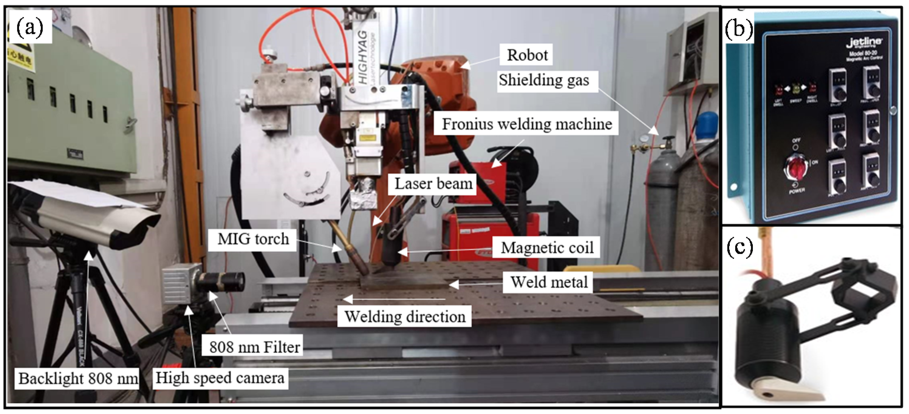
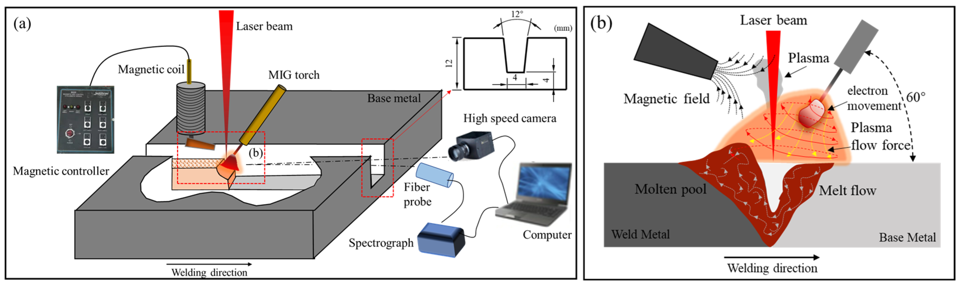
2.2. Experimental Method

Figure 1 shows the experimental setup of laser-MIG hybrid welding assisted by an alternating magnetic field, which mainly consists of a fiber laser (IPG YLS-6000, IPG Photonics, Marlborough, MA, USA) with a maximum power of 6 KW, a digital welding system (FRONIUS TPS4000, Fronius welding Tech., Ltd., Zhuhai, China), and a magnetic arc control system (MA-8020) made by the Jetline Engineering company, Irvine, CA, USA. The laser beam passed through a focusing mirror with the focal length of 350 mm and was finally focused as a spot of 0.3 mm in diameter. The welding system achieving the integration of regulation of current, voltage, and wire feed rate. As shown in Figure 1b,c, the magnetic intensity and frequency can be adjusted by the magnetic controller, and the magnetic intensity at the same position in the center of the weld is measured by a high-precision Gauss meter.
A high-speed camera (CP80-3M540, Ketianjian Optical and Electronic technology, Peking, China) with the acquisition frequency of 4500 frames per second put parallel to the welding direction was used to capture the arc plasma behavior and droplet transfer, as shown in Figure 2a. In this study, the interval time between every two consecutive images was about 0.2 ms. Additionally, the interference filter and the backlight source with an emission wavelength of 808 nm were used to filter out the arc light. To detect the arc plasma in the alternating magnetic field assisted narrow gap laser MIG hybrid welding, the MX2500 emission spectrograph produced by Ocean Insight company (Shanghai, China) was used. The optical emission signals collected by eight fiber probes of different wavelengths are transmitted to the spectrometer, which is converted into electrical signals and drawn into the intensity wavelength curve in the computer software. Exposure time was set to 10 ms by software and the observed spectral domain ranges from 250 to 850 nm in this experiment. Furthermore, three spectral lines of Ar I were selected to estimate the electron temperature and density of the arc plasma. The physical parameters of the spectral lines used in the calculation can be easily obtained in [29]. The Stark broadening is the main factor affecting the spectral line profile [30]. The detailed calculation method of electron density can be found in [31].
As shown in Figure 2b, the welding direction was arc leading laser. The angle of the welding torch and the laser beam to the workpiece surface are 60° and 90°, respectively. Pure Argon with 99.99% concentration is used as a shielding gas. It is also showed that the laser-MIG hybrid welding pool was influenced by the laser beam, arc plasma, and alternating magnetic field. The laser MIG hybrid welding parameters are shown in Table 2. Cross-sectional specimens of the joints were mechanically grounded to 1200 mesh and polished using diamond pastes (0.25 μm), and then etched with Beraha etchant (30 mL HCl + 60 mL H2O + 1 g K2S2O5) for 3–5 s. The morphology of the weld section was observed by optical microscopy.

3. Results and Discussion

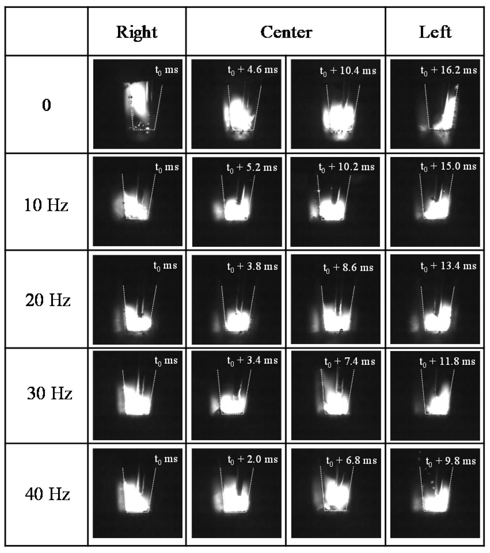
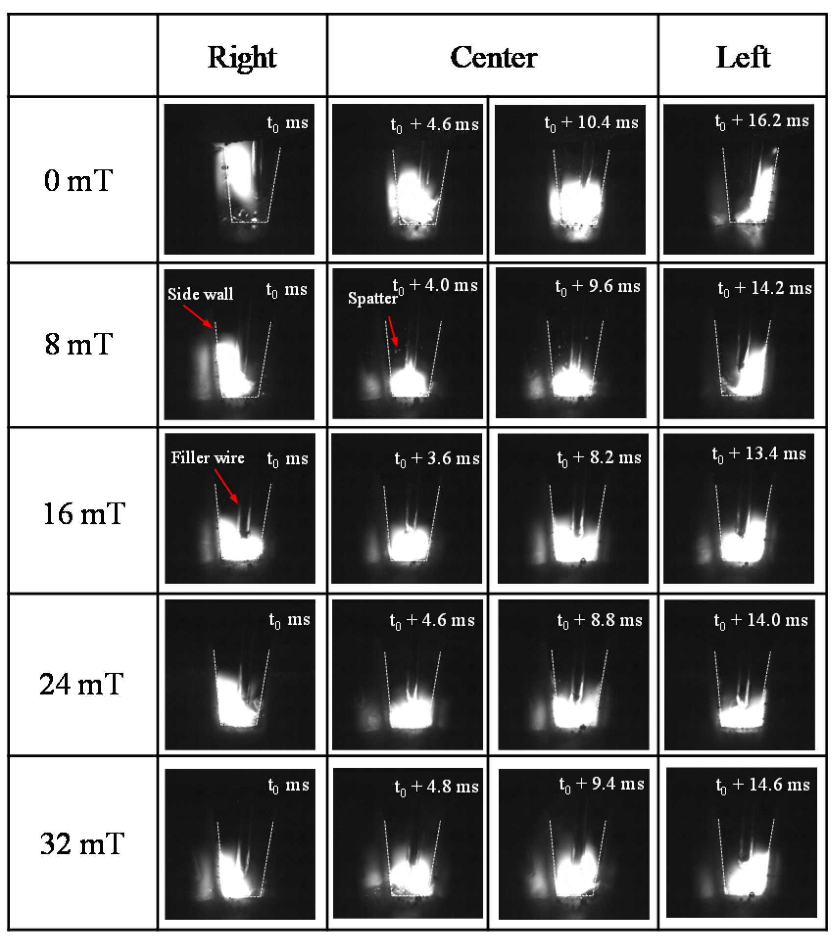
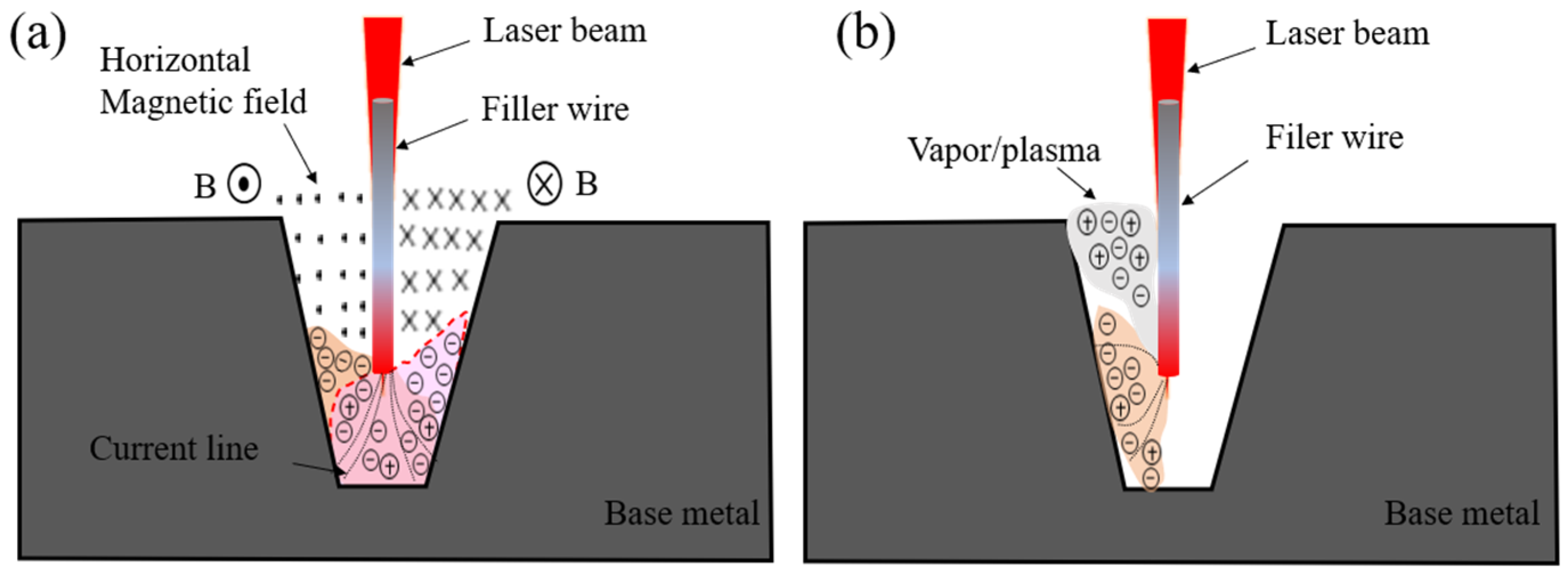
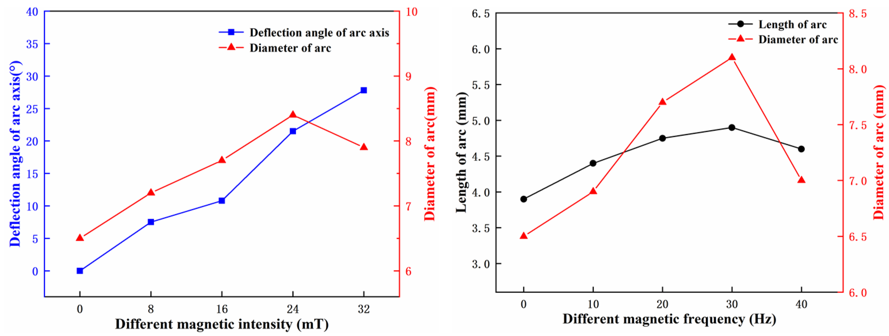
3.1. Behavior of the Arc Plasma

Since the arc is composed of charged particles, the force and direction of movement of the charged particles will be changed by the alternating magnetic field, thus showing the characteristics of complex force and movement, as shown in Figure 2b. The macroscopic appearance is the behavior of the arc plasma. Figure 3 shows the effect of various magnetic intensity on the arc plasma when the magnetic frequency is 20 Hz. It can be clearly seen from the high-speed camera pictures that in the laser MIG welding without magnetic field, the arc had gone through a repeated and unstable process from deflection to the left side of the groove to returning to the center of the groove and then deviating to the right side. In the process of laser-arc hybrid welding of stainless steel, the resistivity of the photoinduced plasma/metal vapor is much smaller than the surrounding atmosphere, which means that the energy required to form a stable arc through the photoinduced plasma/metal vapor is minimal. According to the principle of minimum voltage, the arc has the characteristic of maintaining the minimum energy consumption, so the arc will be deflected by the attraction of the photoinduced plasma/metal vapor. Obviously, the shape of the plasma above the molten pool will continue to change with the oscillation of the molten pool, and the change is random. When the plasma in the groove fluctuates continuously, due to the blocking effect of the side wall, the plasma accumulates on one side wall, which will cause the arc to deflect to the place where the plasma accumulates more, and the arc will be adsorbed on the side wall. The phenomenon is shown in Figure 4.
While applying the alternating magnetic field with intensity ranging from 16 mT to 24 mT, the arc maintained a relatively stable state throughout the entire process, and there was no obvious phenomenon that the arc deviated to a certain side wall. On the one hand, the laser-induced plasma weakens with the increase of the magnetic field intensity. On the other hand, the arc remains in a state of magnetic restraint with the alternating magnetic applied, which effectively solves the problem that the arc is easy to climb along the inner wall in the narrow gap groove. Furthermore, it can be clearly seen from Figure 3 that as B increases to 32 mT, the shape of the arc is unstable. This is due to the fact that the arc rotation speed is too large, resulting in excessive arc oscillation.
Figure 5 shows the effect of various magnetic frequency on the arc plasma when B is 16 mT. The cycle time of the arc swinging back and forth in the narrow gap groove was shortened as the frequency increases, and the arc was unstable and splashes were generated when frequency was over 30 Hz. The swing arc improves the temperature distribution inside the narrow gap groove, so the main defect that is lack of sidewall fusion will be solved.

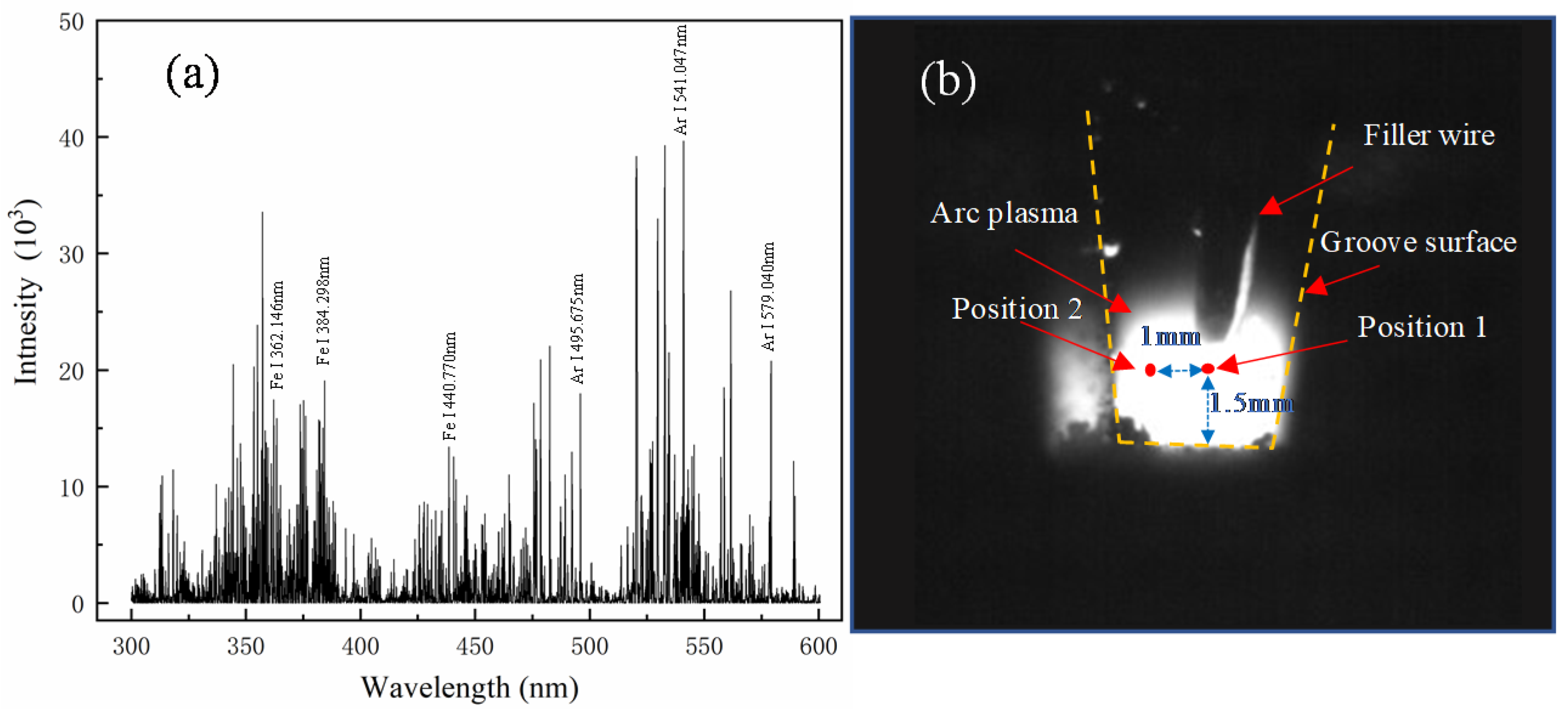
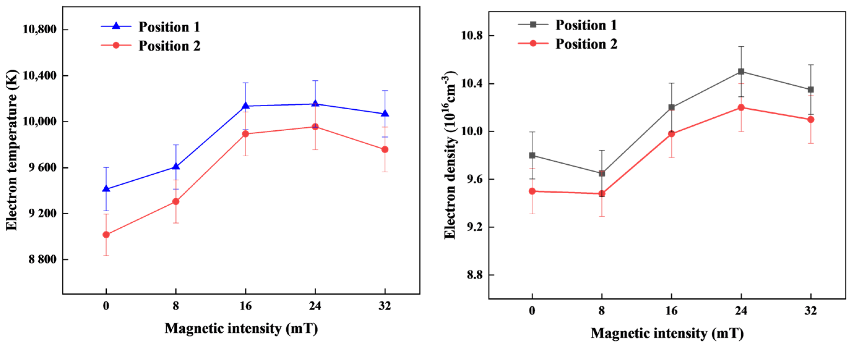
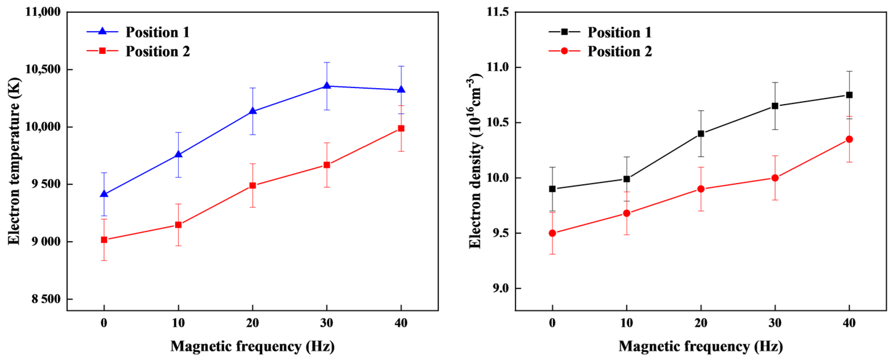
3.2. Electron Temperature and Density of the Arc Plasma

Assuming that the arc plasma is in local thermal equilibrium (LTE), the electron temperature can be estimated to represent the arc plasma temperature by the Boltzmann plot method in spectral diagnose. The following formula is used to calculate the arc plasma temperature [32,33,34]:
I n ( I ki λ ki A ki g ki ) = l n ( nhc Z ) E k KT e
where Iki is the spectral intensity for the transition from k-level to the i-level; λki is the wavelength of emission lines; Aki is the atomic transition probability; gki is k-level statistical weights; n is the population density; Z is the partition function; h is Planck constant; c is the speed of light; Ek is the k-level energy; k is Boltzmann constant; and Te is electron temperature. These parameters are known by the online database of National Institute of Standards and Technology (NIST) after selecting the spectrum line. In this experiment, spectral lines of Ar I 495.675 nm, Ar I 541.047 nm, and Ar I 579.040 nm are selected for the electron temperature and density calculation.
The typical spectrum information collected during the alternating magnetic assisted laser MIG hybrid welding process is shown in Figure 6a. It contains optical signals of different wavelengths, which need to be converted and calculated to obtain the electron density information related to the arc plasma. Stark broadening is the main factor influencing the profile of the spectral lines. In this study, the electron density of the plasma is calculated by the Stark broadening of the characteristic spectral line. The following formula is used [35]:
n e = Δ λ stark 10 16 2 ω
where ne is the electron density; Δλstark is the full width at half maximum of the spectrum measured in the experiment, which can be obtained by Lorentz fitting the selected spectral lines; and ω is the electron collision broadening parameter, which can be acquired in literature [36].
As shown in Figure 6a, the typical spectral lines collected in the arc plasma mainly include Fe I spectral lines and Ar I spectral lines, and the intensity of Ar I spectral lines is significantly greater than that of Fe I spectral lines. It shows that more Ar atoms were ionized in the arc. The Ar atomic spectral lines without obvious self-absorption were selected to calculate the electron temperature and electron density. The acquiring positions of the spectroscopic probe are shown in Figure 6b.
Figure 7 and Figure 8 showed the calculated results of temperature and density of electron, respectively, under different alternating magnetic paraments. It can be seen that the plasma temperature around the center of the arc in the narrow gap is about 8500–10,000 K. For the magnetic assisted hybrid arc plasma, the high-temperature area is located at the front of the filler wire and the maximum value is 10,142.9 K under the magnetic intensity is 16 mT. According to the calculated results shown in Figure 8, the electron temperature raised with the increasing of the magnetic field intensity, which can be used to characterize the movement energy of charged particles. At point 2 near the bottom of the groove, the plasma temperature increased from 9016.4 K to 9893.6 K and the electron density increased from 0.95 × 1017 cm−3 to 0.99 × 1017 cm−3 when the magnetic intensity increased from 0 to 16 mT. A large amount of plasma escapes the arc due to the oscillation and compression of the arc, and the collision of charged particles in the center of the arc is weakened, which reduces the heat loss of the plasma itself. On the other hand, the reduction of the arc surface area also weakens the energy transfer between the plasma and the outside, resulting in the raised of electrons temperature. It is worth noting that the electron temperature and electron density at acquiring position 1 are generally higher than that at position 2. While when the magnetic intensity is 24 mT, the electron temperature difference between the two spectral acquiring points is the smallest, with a gap of only 286.4 K, which indicates that the magnetic intensity can adjust the temperature distribution in the narrow gap groove.
The volume of the arc and the number of electrons is the main factors that affect electron density. As shown in Figure 8, when the alternating magnetic intensity was 8 mT, the arc was elongated and the overall volume of the arc was increased by the interaction between the alternating magnetic field and hybrid arc, but the number of electrons had not increased. Therefore, the electron density, in this case, did not change significantly compared to the absence of a magnetic field. As the intensity of the magnetic field continued to increase, the oscillation of the arc became more greatly. Except for a part of the bursting plasma escaped, the remaining plasma remains in the arc due to the huge rotating force generated by the alternating magnetic field in the arc. The volume is further compressed so that the electron density gradually increased. Moreover, with the increased magnetic frequency, the reason for the increase of electron density is that the arc cathode region expands obviously, and a stable plasma conduct path to connect the arc and laser-induced plasma is formed, which increased the degree of ionization of the arc plasma.

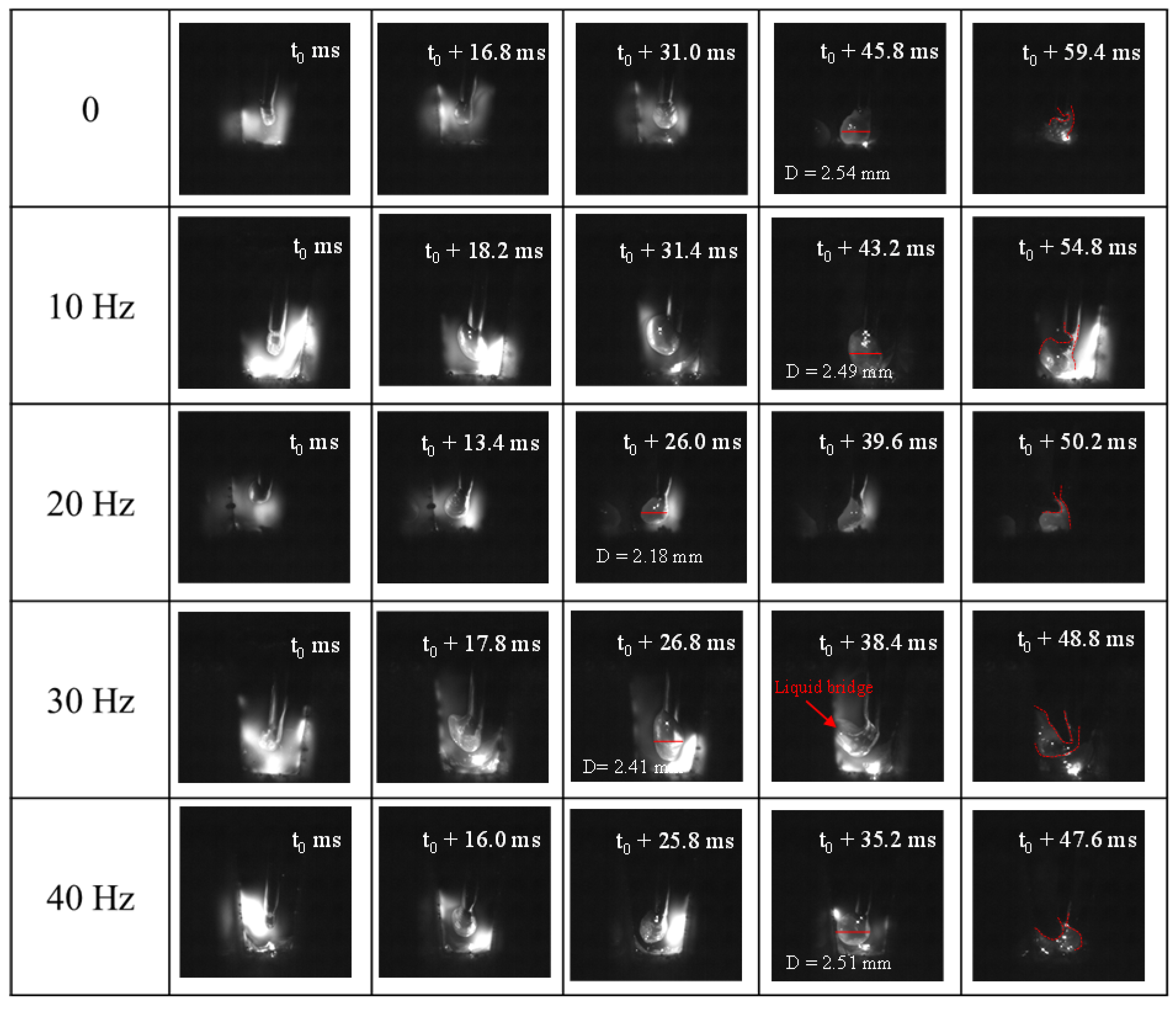
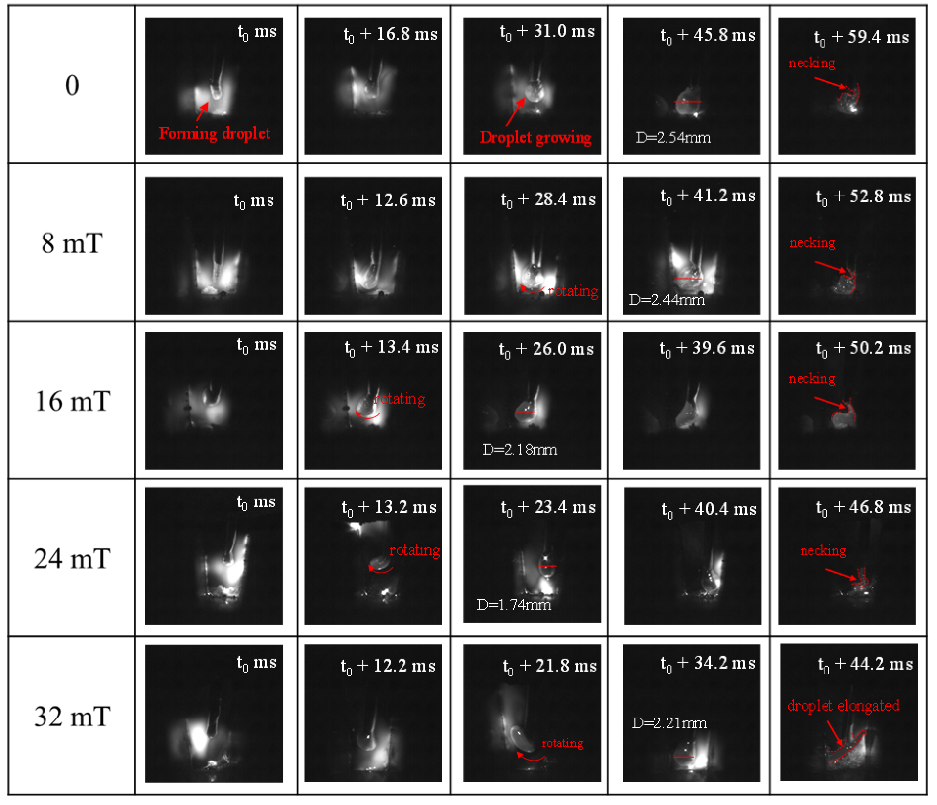
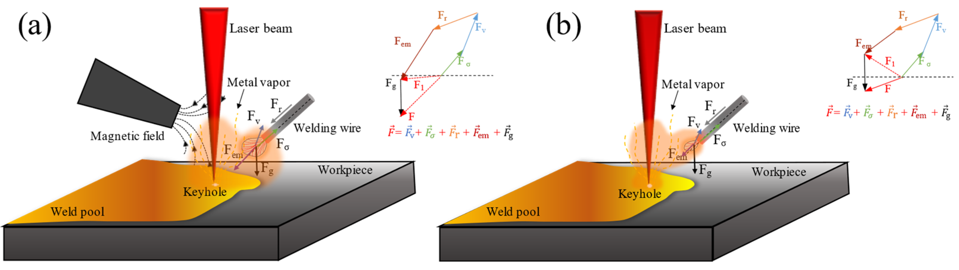
3.3. Droplet Transfer Process of Hybrid Welding Assisted the Alternating Magnetic Field

Figure 9 and Figure 10 presents various conditions of the droplet transfer process under different magnetic paraments. In general, the whole process was divided into three stages: when the droplets are formed; when the droplets grow up to contact the molten pool and form an effective liquid bridge; and when the liquid bridge necks and breaks. Without the external alternating magnetic field, the droplet forms and grow up at the filler wire tip. Finally, the liquid metal is drawn into the molten pool by the electromagnetic pinch force generated by the short-circuit current and the surface tension of the liquid metal. At the same time, the axis of the droplet is easily biased toward the keyhole, causing the droplet transfer channel to be attracted by the laser-induced plasma, whereafter a consequent neck breaks and forms spatters. As shown in Figure 10, the phenomenon that the droplet rotates around its central axis by the electromagnetic force occurred when the magnetic intensity increases to 16 mT. The rotation and oscillation of the droplet cause its shape to be drawn from a spherical shape to an ellipsoid shape, and then under the action of the arc force, the droplet is adsorbed to the sidewall of the groove to form a short-circuit transition, which also reduced the cycle time of the droplet transfer. This appearance was mainly attributed to the centrifugal force during droplet spinning. While applying the alternating magnetic field with a frequency ranging from 10 Hz to 40 Hz, as shown in Figure 10, the droplet-transfer channel was optimized. Furthermore, the droplet diameter is almost invariable.
Furthermore, droplet diameter and transition frequency with variations of magnetic intensity and frequency were measured and plotted in Figure 11. When the magnetic intensity increases from 8 mT to 24 mT, the droplet transition frequency increases from 17 to 21 drops per second on average. However, the droplet diameter decreases from 2.44 mm to 1.74 mm, indicating that the alternating magnetic intensity has a promoting effect on the droplet transition. In other words, the applied alternating magnetic field is beneficial to the droplet transition and the spread of molten metal in the narrow gap groove. Therefore, stable and effective droplet transfer can be obtained and welding defects such as spatters and process pores can be avoided through the optimized magnetic paraments.
Figure 12 shows a schematic diagram of force analysis of droplet transfer during alternating magnetic assisted narrow gap laser hybrid welding process. Generally, the forces acting on the droplets in the hybrid welding process mainly include gravity (Fg), plasma flow force (Fr), electromagnetic contraction force (Fem), surface tension (Fσ), and metal vapor reaction force (Fv). Where the Fg, Fr, and Fem promote droplet transfer, the Fσ and Fv prevent droplet transfer. The electromagnetic contractile force is the macroscopic reflection of the Lorenz force, which plays an important role in the droplet transfer process, as shown in Equation (3) [37]:
F em = μ 0 4 π I 2 [ ln r d sin θ R 1 4 1 1 cos θ + 2 1 ( 1 cos θ ) 2 ln 2 1 + cos θ ]
where I is welding current, rd is droplet radius, R is wire radius, θ is arc hanging angle, and μ0 is the permeability of free space (4π × 10−7 N∙A−2). θ decreases with the increasing of magnetic intensity. As shown in Figure 12, when a magnetic field is applied, the current lines that affect the electromagnetic force are denser than those without a magnetic field, which promotes droplet transfer. The droplet transfer process is mainly determined by gravity and electromagnetic contraction force. In addition, as shown in Figure 12a, with the applied alternating magnetic field, the direction and magnitude of the electromagnetic contraction force had changed, which affects the resultant force. According to related studies, as the intensity of the magnetic field increases, the current lines are more uniform, concentrated and are not affected by laser-induced plasma [38].

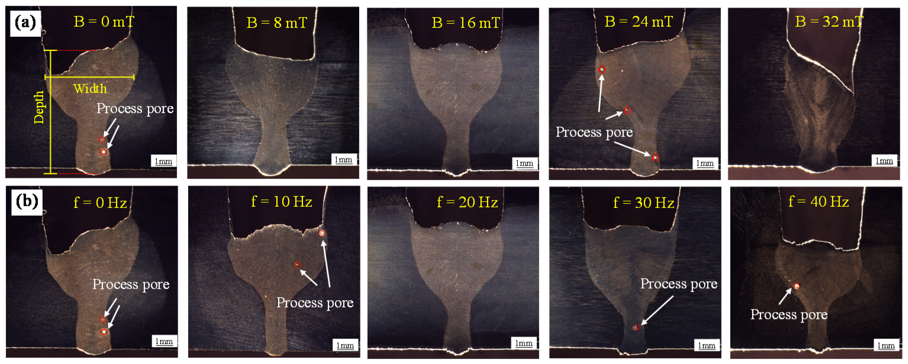
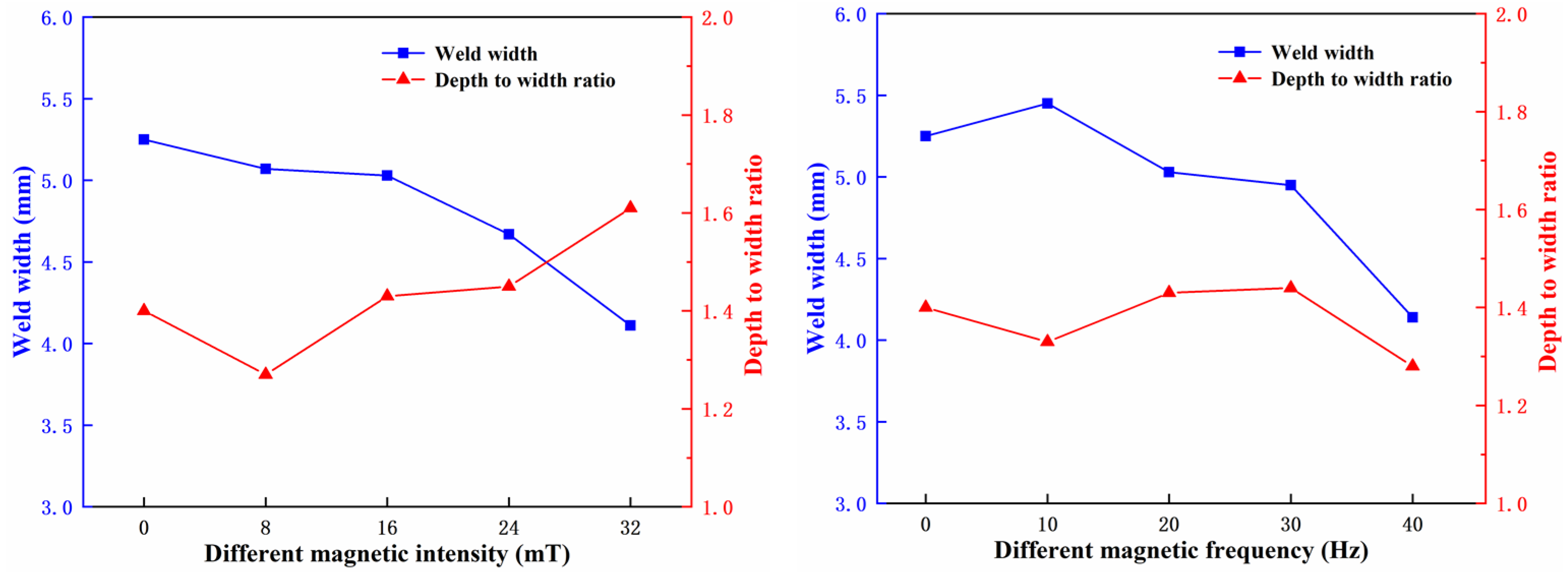
3.4. Effect of Alternating Magnetic on the Appearance of Weld Cross-Section

Figure 13 shows the cross-sectional morphology of the weld under different magnetic field strengths and frequencies. It can be seen that even without applying an alternating magnetic field, the process parameters used in this study could completely penetrate 4 mm thick stainless steel. However, after the alternating magnetic field was applied, the appearance of the cross-section of the weld was changed due to the optimization of the arc shape and the movement state of the molten metal, and the pores in the weld bead were improved. The main reason is that electromagnetic stirring reduces the saturation of the gas in the liquid metal, and the possibility of bubbles generated is reduced. Even after the formation of tiny pores, the flow of liquid metal in the molten pool increases the probability of bubbles gathering and growing, which is beneficial to their floating. The liquid metal in the molten pool is pushed in other directions due to the Lorentz force, which causes the lateral convection to be generated and the flow velocity is increased [39].
Figure 14 presents the weld width and the depth to width ratio under different magnetic intensity and frequency. As the intensity of the magnetic field reaches 24 mT, the width of the weld increases from 4.67 mm to 5.25 mm, and the depth to width ratio of the weld increases from 1.4 to 1.6. This is due to the fact that an alternating magnetic field is applied to the hybrid arc, then the hybrid arc plasma will oscillate and rotate in the direction of the arc axis, which can enhance the arc stiffness, concentrate the welding arc energy, and improve the penetration ability of the arc. When the magnetic frequency is increased from 10 Hz to 30 Hz, the size of the weld cross-section does not change significantly, indicating that the alternating magnetic intensity has a greater influence on the shape of the weld cross-section than the magnetic frequency.

4. Conclusions

In this study, the effect of alternating magnetic field on droplet transition and arc plasma characteristics during narrow gap laser-MIG hybrid welding of 2205 duplex stainless steel was investigated. The main results are summarized as follows:
(1) With the alternating magnetic field was applied, the laser-induced plasma weakened with the increase of magnetic intensity, while the arc maintained a relatively stable state and rotated at a high speed to enhance the arc stiffness and further improved the stability of the arc. Under the conditions of laser MIG hybrid welding (3.5 kW, 200 A, 1.0 m/min), the optimized parameter of magnetic field intensity and frequency was B = 16 mT, f = 20 Hz. Meanwhile, the weld formation was improved by the slight swing of the arc.
(2) The electron temperature and electron density in the narrow gap groove increased with the increasing of magnetic field intensity and frequency. At point 2 near the bottom of the groove, the electron temperature increased from 9016.4 K to 9893.6 K and the electron density increased from 0.95 × 1017 cm−3 to 0.99 × 1017 cm−3, when the magnetic intensity increased from 0 to 16 mT. The electron temperature and density increased by 9.7% and 4.2%, respectively. The results showed that the electron temperature distribution in the narrow gap groove was more uniform within the optimum magnetic field parameters.
(3) The droplet transfer mode was a short-circuit transfer, and the changed current distribution led to a downward and inward electromagnetic force near the bottom of the droplet, which decreased the droplet transition cycle time and promotes droplet transfer. When the magnetic field intensity of 16 mT was applied, the droplet diameter was 2.18 mm that decreased by 17.6%, and the transition frequency increased by 23.5% compared with that without magnetic field.
(4) The well-penetration weld bead was acquired with the alternating magnetic intensity range of 8–24 mT, the weld width and the depth to width ratio were increased by 12.4% and 14.3%, which was attributed that the laser-MIG heat source could be absorbed more adequately. Furthermore, the pores were also significantly reduced due to the stirring of the magnetic field on the molten pool.

Author Contributions

Data curation, B.C., J.F., and Y.Z.; funding acquisition, Y.Q., and S.S.; investigation, F.C.; methodology, J.F., and F.C.; writing—original draft, B.C., J.F., and F.C.; writing—review and editing, Y.Z. All authors have read and agreed to the published version of the manuscript.

Funding

This work was supported by the National Key Research and Development Program of China (No. 2018YFC0310400), Jiangsu Province Production-university-research Cooperation Project (Grant No. BY2020449), The 65th batch of China Postdoctoral Science Foundation (Grant No. 2019M651759) and Postdoctoral Research Foundation of Jiangsu Province (Grant No. 2021K533C).

Institutional Review Board Statement

Not applicable.

Informed Consent Statement

Not applicable.

Data Availability Statement

The data used to support the findings of this study are available from the corresponding author upon request.

Conflicts of Interest

The authors declare no conflict of interest.

References

  1. Li, R.; Wang, T.; Wang, C.; Yan, F.; Shao, X.; Hu, X.; Li, J. A study of narrow gap laser welding for thick plates using the multi-layer and multi-pass method. Opt. Laser Technol. 2014, 64, 172–183. [Google Scholar] [CrossRef]
  2. Oliveira, J.; Shen, J.; Escobar, J.; Salvador, C.; Schell, N.; Zhou, N.; Benafan, O. Laser welding of H-phase strengthened Ni-rich NiTi-20Zr high temperature shape memory alloy. Mater. Des. 2021, 202, 109533. [Google Scholar] [CrossRef]
  3. Oliveira, J.; Crispim, B.; Zeng, Z.; Omori, T.; Fernandes, F.B.; Miranda, R. Microstructure and mechanical properties of gas tungsten arc welded Cu-Al-Mn shape memory alloy rods. J. Mater. Process. Technol. 2019, 271, 93–100. [Google Scholar] [CrossRef]
  4. Oliveira, J.P.; Shen, J.; Zeng, Z.; Park, J.M.; Choi, Y.T.; Schell, N.; Maawad, E.; Zhou, N.; Kim, H.S. Dis-similar laser welding of a CoCrFeMnNi high entropy alloy to 316stainless steel. Scr. Mater. 2022, 206, 114219. [Google Scholar] [CrossRef]
  5. Liu, F.; Tan, C.; Gong, X.; Wu, L.; Chen, B.; Song, X.; Feng, J. A comparative study on microstructure and mechanical properties of HG785D steel joint produced by hybrid laser-MAG welding and laser welding. Opt. Laser Technol. 2020, 128, 106247. [Google Scholar] [CrossRef]
  6. Zhan, X.; Zhao, Y.; Liu, Z.; Gao, Q.; Bu, H. Microstructure and porosity characteristics of 5A06 aluminum alloy joints using laser-MIG hybrid welding. J. Manuf. Process. 2018, 35, 437–445. [Google Scholar] [CrossRef]
  7. Chen, X.; Fu, J.; Zhao, Y.; Jiang, Y.; Yan, K.; Jiang, C.; Chen, J. Melting behavior in ultrasonic-assisted narrow-gap laser welding with filler wire. J. Laser Appl. 2021, 33, 012058. [Google Scholar] [CrossRef]
  8. Elmesalamy, A.S.; Li, L.; Francis, J.A.; Sezer, H.K. Understanding the process parameter interactions in multiple-pass ultra-narrow-gap laser welding of thick-section stainless steels. Int. J. Adv. Manuf. Technol. 2013, 68, 1–17. [Google Scholar] [CrossRef]
  9. Zhao, Y.; Zhu, K.; Ma, Q.; Shang, Q.; Huang, J.; Yang, D. Plasma behavior and control with small diameter assisting gas nozzle during CO2 laser welding. J. Mater. Process. Technol. 2016, 237, 208–215. [Google Scholar] [CrossRef]
  10. Liu, S.; Chen, S.; Wang, Q.; Li, Y.; Zhang, H.; Ding, H. Analysis of plasma characteristics and conductive mechanism of laser assisted pulsed arc welding. Opt. Lasers Eng. 2017, 92, 39–47. [Google Scholar] [CrossRef]
  11. Chen, M.; Xu, J.; Xin, L.; Zhao, Z.; Wu, F. Comparative study on interactions between laser and arc plasma during laser-GTA welding and laser-GMA welding. Opt. Lasers Eng. 2016, 85, 1–8. [Google Scholar] [CrossRef]
  12. Kim, Y.-C.; Hirohata, M.; Murakami, M.; Inose, K. Effects of heat input ratio of laser–arc hybrid welding on welding distortion and residual stress. Weld. Int. 2014, 29, 245–253. [Google Scholar] [CrossRef]
  13. Li, R.; Yue, J.; Sun, R.; Mi, G.; Wang, C.; Shao, X. A study of droplet transfer behavior in ultra-narrow gap laser arc hybrid welding. Int. J. Adv. Manuf. Technol. 2016, 87, 2997–3008. [Google Scholar] [CrossRef]
  14. Ming, G.; Xiaoyan, Z.; Qianwu, H. Effects of gas shielding parameters on weld penetration of CO2 laser-TIG hybrid welding. J. Mater. Process. Technol. 2007, 184, 177–183. [Google Scholar] [CrossRef]
  15. Wang, J.; Wang, C.; Meng, X.; Hu, X.; Yu, Y.; Yu, S. Interaction between laser-induced plasma/vapor and arc plasma during fiber laser-MIG hybrid welding. J. Mech. Sci. Technol. 2011, 25, 1529–1533. [Google Scholar] [CrossRef]
  16. Huang, A.; Zhang, J.; Gao, C.; Hu, R.; Pang, S. Effects of groove constraint space on plasma characteristics during Laser-MIG hybrid welding of Titanium alloy. J. Manuf. Process. 2019, 48, 137–144. [Google Scholar] [CrossRef]
  17. Sun, D.; Cai, Y.; Wang, Y.; Wu, Y.; Wu, Y. Effect of He–Ar ratio of side assisting gas on plasma 3D formation during CO2 laser welding. Opt. Lasers Eng. 2014, 56, 41–49. [Google Scholar] [CrossRef]
  18. Li, G.; Cai, Y.; Wu, Y. Stability information in plasma image of high-power CO2 laser welding. Opt. Lasers Eng. 2009, 47, 990–994. [Google Scholar] [CrossRef]
  19. Wang, C.-M.; Meng, X.-X.; Huang, W.; Hu, X.-Y.; Duan, A.-Q. Role of side assisting gas on plasma and energy transmission during CO2 laser welding. J. Mater. Process. Technol. 2011, 211, 668–674. [Google Scholar] [CrossRef]
  20. Zhao, Y.; Ma, S.; Huang, J.; Wu, Y. Narrow-gap laser welding using filler wire of thick steel plates. Int. J. Adv. Manuf. Technol. 2017, 93, 2955–2962. [Google Scholar] [CrossRef]
  21. Zhao, Y.; Yang, Q.; Huang, J.; Zou, J.; Wu, Y. Droplet transfer and weld geometry in laser welding with filling wire. Int. J. Adv. Manuf. Technol. 2017, 90, 2153–2161. [Google Scholar] [CrossRef]
  22. Campana, G.; Fortunato, A.; Ascari, A.; Tani, G.; Tomesani, L. The influence of arc transfer mode in hybrid laser-mig welding. J. Mater. Process. Technol. 2007, 191, 111–113. [Google Scholar] [CrossRef]
  23. Lei, Z. Characteristics of droplet transfer in CO2 laser-MIG hybrid welding with short-circuiting mode. Chin. J. Mech. Eng. 2006, 19, 172–175. [Google Scholar] [CrossRef]
  24. Li, M.; Xu, J.; Huang, Y.; Rong, Y. Improving Keyhole Stability by External Magnetic Field in Full Penetration Laser Welding. JOM 2018, 70, 1261–1266. [Google Scholar] [CrossRef]
  25. Wang, L.; Chen, J.; Wu, C. Numerical investigation on the effect of process parameters on arc and metal transfer in magnetically controlled gas metal arc welding. J. Vac. 2020, 177, 109391. [Google Scholar] [CrossRef]
  26. Yang, B.; Liu, F.; Tan, C.; Wu, L.; Chen, B.; Song, X.; Zhao, H. Influence of alternating magnetic field on microstructure and mechanical properties of laser-MIG hybrid welded HG785D steel joint. J. Mater. Res. Technol. 2020, 9, 13692–13705. [Google Scholar] [CrossRef]
  27. Wang, L.; Chen, J.; Wu, C.; Gao, J. Backward flowing molten metal in weld pool and its influence on humping bead in high-speed GMAW. J. Mater. Process. Technol. 2016, 237, 342–350. [Google Scholar] [CrossRef]
  28. Wang, J.; Sun, Q.; Feng, J.; Wang, S.; Zhao, H. Characteristics of welding and arc pressure in TIG narrow gap welding using novel magnetic arc oscillation. Int. J. Adv. Manuf. Technol. 2017, 90, 413–420. [Google Scholar] [CrossRef]
  29. National Institute of Standards and Technology Database. 2019. Available online: https://physics.nist.gov/PhysRefData/ASD/lines_form.html (accessed on 25 December 2019).
  30. Griem, H. Spectral Line Broadening by Plasma; New York Academic: New York, NY, USA, 1974. [Google Scholar]
  31. Liu, L.; Chen, M. Interactions between laser and arc plasma during laser–arc hybrid welding of magnesium alloy. Opt. Lasers Eng. 2011, 49, 1224–1231. [Google Scholar] [CrossRef]
  32. Griem, H.R. Principles of Plasma Spectroscopy; Cambridge University Press (CUP): Cambridge, UK, 1997; pp. 187–212. [Google Scholar]
  33. Zhang, Y.; Li, L.; Zhang, G. Spectroscopic measurements of plasma inside the keyhole in deep penetration laser welding. J. Phys. D Appl. Phys. 2005, 38, 703–710. [Google Scholar] [CrossRef]
  34. Lacroix, D.; Jeandel, G.; Boudot, C. Spectroscopic characterization of laser-induced plasma created during welding with a pulsed Nd:YAG laser. J. Appl. Phys. 1997, 81, 6599–6606. [Google Scholar] [CrossRef]
  35. Jiang, M.; Tao, W.; Wang, S.; Li, L.; Chen, Y. Effect of ambient pressure on interaction between laser radiation and plasma plume in fiber laser welding. Vacuum 2017, 138, 70–79. [Google Scholar] [CrossRef]
  36. Griem, H.R.; Barr, W.L. Spectral Line Broadening by Plasmas. IEEE Trans. Plasma Sci. 1975, 3, 227. [Google Scholar] [CrossRef]
  37. Liu, S.; Zhang, F.; Dong, S.; Zhang, H.; Liu, F. Characteristics analysis of droplet transfer in laser-MAG hybrid welding process. Int. J. Heat Mass Transf. 2018, 121, 805–811. [Google Scholar] [CrossRef]
  38. Zhang, X.; Zhao, Z.; Mi, G.; Wang, C.; Li, R.; Hu, X. Effect of external longitudinal magnetic field on arc plasma characteristics and droplet transfer during laser-MIG hybrid welding. Int. J. Adv. Manuf. Technol. 2017, 92, 2185–2195. [Google Scholar] [CrossRef]
  39. Meng, X.; Artinov, A.; Bachmann, M.; Rethmeier, M. Theoretical study of influence of electromagnetic stirring on transport phenomena in wire feed laser beam welding. J. Laser Appl. 2020, 32, 022026. [Google Scholar] [CrossRef]
Figure 1. Laser MIG (metal inert gas) hybrid welding experimental equipment: (a) experimental setup of laser MIG hybrid welding and (b) magnetic arc control unit; (c) magnetic arc probe.
Metals 11 01712 g001
Figure 2. The schematic diagram of the alternating magnetic field assisted laser-MIG hybrid welding: (a) schematic diagram of welding equipment and (b) schematic diagram of welding process.
Metals 11 01712 g002
Figure 3. Arc shape under different magnetic intensity with a fixed frequency of 20 Hz.
Metals 11 01712 g003
Figure 4. Schematic diagram of arc plasma behavior of narrow gap groove: (a) with alternating magnetic field; (b) without magnetic field. (B: magnetic flux density).
Metals 11 01712 g004
Figure 5. Arc shape under different magnetic frequency with a fixed intensity of 16 mT.
Metals 11 01712 g005
Figure 6. Spectrum of arc plasma in laser-MIG hybrid welding with magnetic field: (a) plasma spectrum and (b) spectral acquisition positions.
Metals 11 01712 g006
Figure 7. Effect of magnetic intensity on electron density and temperature at different positions.
Metals 11 01712 g007
Figure 8. Effect of magnetic frequency on electron density and temperature at different positions.
Metals 11 01712 g008
Figure 9. Droplet transfer process at 20 Hz with different magnetic intensity.
Metals 11 01712 g009
Figure 10. Droplet transfer process at 16 mT with different magnetic frequency.
Metals 11 01712 g010
Figure 11. Average droplet diameter and transition frequency under different magnetic intensity and frequency.
Metals 11 01712 g011
Figure 12. Force analysis of droplet transfer: (a) with magnetic field and (b) without magnetic field.
Metals 11 01712 g012
Figure 13. The appearance of weld cross-section under different magnetic intensity and frequency: (a) at 20 Hz with different magnetic intensity and (b) at 16 mT with different magnetic frequency.
Metals 11 01712 g013
Figure 14. Weld width and depth to width ratio under different magnetic intensity and frequency.
Metals 11 01712 g014
Table 1. The chemical compositions of 2205 duplex stainless steel and filler wire (wt %).
MaterialsCCrNiMoMnSiNPS
22050.01622.505.603.201.200.500.170.0210.001
ER22090.0223.009.001.203.300.550.1600.0130.008
Table 2. Welding parameters.
Welding ParametersValue
Laser power P (kW)3.5
Weld current I (A)200
Welding speed v (m/min)1.0
Defocusing distance (mm)0
Distance between laser and arc DLA (mm)2
Shielding gas flow rate (L/min)15
Magnetic intensity (mT)8, 16, 24, 32
Magnetic frequency (Hz)10, 20, 30, 40
Publisher’s Note: MDPI stays neutral with regard to jurisdictional claims in published maps and institutional affiliations.

