Article

Droplet Transfer Induced Keyhole Fluctuation and Its Influence Regulation on Porosity Rate during Hybrid Laser Arc Welding of Aluminum Alloys

College of Materials Science and Technology, Nanjing University of Aeronautics and Astronautics, Nanjing 211106, China
*
Authors to whom correspondence should be addressed.
Metals 2021, 11(10), 1510; https://doi.org/10.3390/met11101510
Submission received: 24 August 2021 / Revised: 17 September 2021 / Accepted: 20 September 2021 / Published: 23 September 2021
(This article belongs to the Special Issue Laser Welding Technology)

Abstract

:
Hybrid laser arc welding (HLAW) features advantages such as higher welding speed and gap tolerance as well as smaller welding deformation and heat-affected zone than arc welding. Porosity in hybrid laser arc weld due to keyhole fluctuation tends to be the initial source of crack propagation, which will significantly diminish the weld performance. A high-speed imaging technique was adopted to record and analyze the droplet transfer and keyhole fluctuation behavior during hybrid laser arc welding of aluminum alloys. A heat transfer and fluid flow model of HLAW was established and validated for a perspective of the evolution process of droplet transfer and keyhole fluctuation. The relationship between keyhole fluctuation and weld porosity was also revealed. During the droplet transfer stage, liquid metal on the top surface of the weld pool flows toward the keyhole originated by globular transfer, and the keyhole fluctuates and decreases significantly, which has a higher tendency to form a bubble in the weld pool. The bubble evolves into porosity once trapped in the mush-zone near the trailing edge of the weld pool. Therefore, globular transfer during HLAW is the principal origin of keyhole fluctuation and weld porosity. Welding current has a significant influence on keyhole fluctuation and weld porosity rate. Droplet transfer frequency, keyhole fluctuation, and porosity rate increase with higher welding current under the globular transfer mode. The porosity rate shows a nearly positive correlation with the standard deviation of keyhole fluctuation.

1. Introduction

Laser beams have recently been reported as the heat source in the joining of several novel materials [1,2]. Arc welding is a promising technique for fabricating defect-free joints despite the lower production rate [3]. Arc welding is integrated into laser welding to reduce porosity and improve gap tolerance during hybrid laser arc welding (HLAW). A schematic diagram and experimental setup of HLAW are shown in Figure 1. Prepositive laser beam and postpositive arc heat sources have a combined heat effect on the weld pool. A keyhole is a vapor-filled depression during hybrid laser arc welding and is associated with the onset of vaporization of the liquid metal at a critical power density [4,5]. The droplet at the bottom of the welding wire grows gradually under the action of arc heating and finally rushes into the weld pool at high speed driven by gravity and electromagnetic force [6]. HLAW has been used to join aluminum alloys, titanium alloys, stainless alloys, and nickel-based alloys [7,8,9,10,11]. HLAW has attracted considerable attention from the transportation industry, such as aerospace, high-speed trains, and automobile manufacturing [12,13,14,15]. Compared with arc welding, HLAW has the following advantages: greater weld penetration [16,17]; higher welding speed [18,19]; smaller welding deformation and residual stress [20,21]; shallower heat-affect zones [22,23].
The fluid flow velocity in the weld pool can reach 1 m/s level under normal circumstances [24]. Once keyhole fluctuation results in a sharp change of keyhole dimension, the liquid metal from another region of the weld pool rapidly seals the top of the keyhole. At this time, the keyhole becomes a giant bubble surrounded by liquid metal. Once the giant bubble is trapped in the mushy zone rather than escaping from the top surface of the weld pool, the bubble becomes porosity and remains permanently in the weld [25,26]. Keyhole fluctuation behavior is strictly related to the number and distribution characteristics of pores in hybrid laser arc welds [27].
A high-speed imaging technique has been adopted to observe the droplet transfer and keyhole fluctuation behavior, but due to the limitation of camera shooting range, only the morphology change of the keyhole top surface can be recorded [28]. Bunaziv et al. [29] carried out HLAW of 5 mm thickness 5083 aluminum alloy with prepositive laser mode and prepositive arc mode, and the porosity characteristics under different process parameters were analyzed. Results indicated that lower welding speed or higher arc power could maintain the stability of the keyhole and effectively reduced the porosity. Zhan et al. [30] carried out comparative experiments between HLAW and arc welding of 6.9 mm thickness 5A06 aluminum alloy, and the effects of different process parameters on porosity distribution and porosity rate were investigated. The weld was divided into three regions in the direction of penetration. It is found that the porosity rate of the upper region of the weld is higher due to the bubble floating. The welding joint with lower porosity and better weld formation can be obtained with a 3 m/min welding speed.
Numerical simulation method has been adopted to reconstruct the droplet transfer and keyhole fluctuation behavior, which could deeply understand the evolution process of the keyhole. Numerical simulation of keyhole behavior has also attracted the attention of scholars worldwide. Zhao et al. [31] established a three-dimensional finite element model by Marc to study the thermal field distribution of the laser-MIG hybrid welding process. Numerical simulations of keyhole evolution and bubble motion were absent due to the limitations of the model. Ke et al. [32] presented a numerical framework of keyhole-induced porosity formation and methods to suppress porosity in laser beam oscillating welding, which pointed out a pathway to reveal the mechanism of porosity formation by means of numerical analysis. Lu et al. [33] proposed a three-dimensional transient coupling model of fluid flow, bubble movement, and solidification to study the formation process of keyhole-induced porosity to understand the relationship between dynamic keyhole behavior and porosity formation under various parameters. The simulation results showed that the number of pores was mainly determined by the frequency of keyhole collapse. Keyholes tended to collapse more frequently with higher laser power and gap size as well as lower welding speed and spot diameter. However, the porosity depended not only on the number of bubbles in the weld pool but also on the evolution efficiency from bubble to pore. Zhang et al. [34] carried out the experiment of HLAW of invar thick alloy plate with prepositive laser mode, and established a numerical model to simulate the fluid flow and temperature field, and analyzed the evolution process of two-dimensional keyhole morphology. The results showed that the locked liquid bridge would cause the keyhole to collapse, which led to the formation of porosity in the hybrid laser arc weld. Keyhole depth is the vertical distance from the deepest keyhole position to the upper surface of the substrate. The increase of keyhole depth could be divided into three stages: rapid linear growth stage, oscillation growth stage, and flattening stage. Xu et al. [35] carried out HLAW of 6 mm 6061 aluminum alloy with 5356 welding wire. The porosity of weld from the longitudinal section was measured by X-ray nondestructive testing, and the formation of the keyhole porosity was simulated by a two-dimensional fluid flow model. The results indicated that under the action of arc force, there were relatively stable counterclockwise vortices in the middle and back of the weld pool, which often prevented the bubble from moving to the low-temperature region at the back of the pool, so it was helpful for the bubble to float upward and reduced the porosity.
In summary, although keyhole fluctuation has a significant influence on the porosity rate and distribution during the HLAW process, the quantitative correlation mechanism between keyhole fluctuation and porosity rate has not been established yet. In this paper, the fluid simulation method is implemented to investigate the multiphase coupling behavior and keyhole fluctuation in HLAW. The experimental results are adopted to validate the fluid flow model, and the simulation results are used to study the formation mechanism of weld porosity. Finally, the relationship between keyhole fluctuation and weld porosity is quantitatively investigated. The numerical simulation of the fluid flow in the HLAW process of aluminum alloy is supportive for an understanding of the dynamic evolution process of the keyhole. The mechanism of keyhole fluctuation on porosity distribution and rate is revealed.

2. Materials and Methods

2.1. Material Fabrication

Previous studies have indicated that aluminum had a higher tendency in chaotic keyholes than stainless steel and titanium alloy [36]. Therefore, a commercial 6061 aluminum alloy plate with dimensions of 150 mm × 30 mm × 6 mm is selected as the substrate. The joint is designed as a butt joint with a 30° groove angle and 1 mm height blunt edge. ER4047 welding wire with a diameter of 1.2 mm is selected to deposit the joint. Table 1 shows the chemical compositions of the 6061 aluminum alloy substrate. 6061 aluminum alloy chiefly contains alloy elements Mg and Si, which can compose the Mg2Si strengthening phase. Among them, the Mg generally plays the role of solid-solution strengthening; Mn and Cr can remove certain harmful Fe, which is beneficial to improve the comprehensive properties of the material; Ti can refine the grain and control the recrystallization structure to a certain extent; a small amount of Cu and Zn can improve the strength of the alloy without reducing the corrosion resistance.
The laser head and welding torch are integrated on the arm of the six-axis robot (KUKA KR 60HA, Shanghai, China). Gas metal arc welding (MIG) was adopted during the hybrid laser arc welding process. Prior to the HLAW experiment, the surface of the workpiece was polished and dried. To observe the weld pool morphology and droplet transfer during HLAW, the high-speed camera system was established. An auxiliary laser and high-speed camera are distributed at the top of the substrate on the same side. The plane of the laser head and welding torch are perpendicular to the workbench. The scope of the high-speed camera is in the middle of the weld. The definition of the reference object in the field of vision is controlled by focusing, and the shooting brightness is controlled by adjusting the aperture size. Trudisk-12003 disk laser (TRUMPF, Suzhou, China) was used in the laser source. The defocusing amount of the laser beam is 0 mm. The shielding gas is 99.99% purity argon with a gas flow rate of 15 L/min. To study the effects of different process parameters on the macro morphology, porosity, and weld pool flow of HLAW joint, the experimental parameters were designed according to the principle of a single variable, including welding speed and arc current. Based on the previous experimental results, the process parameters during hybrid laser arc welding are presented in Table 2. Case 2 has a higher welding current than Case 1. Case 4 has a lower welding speed than Case 3.

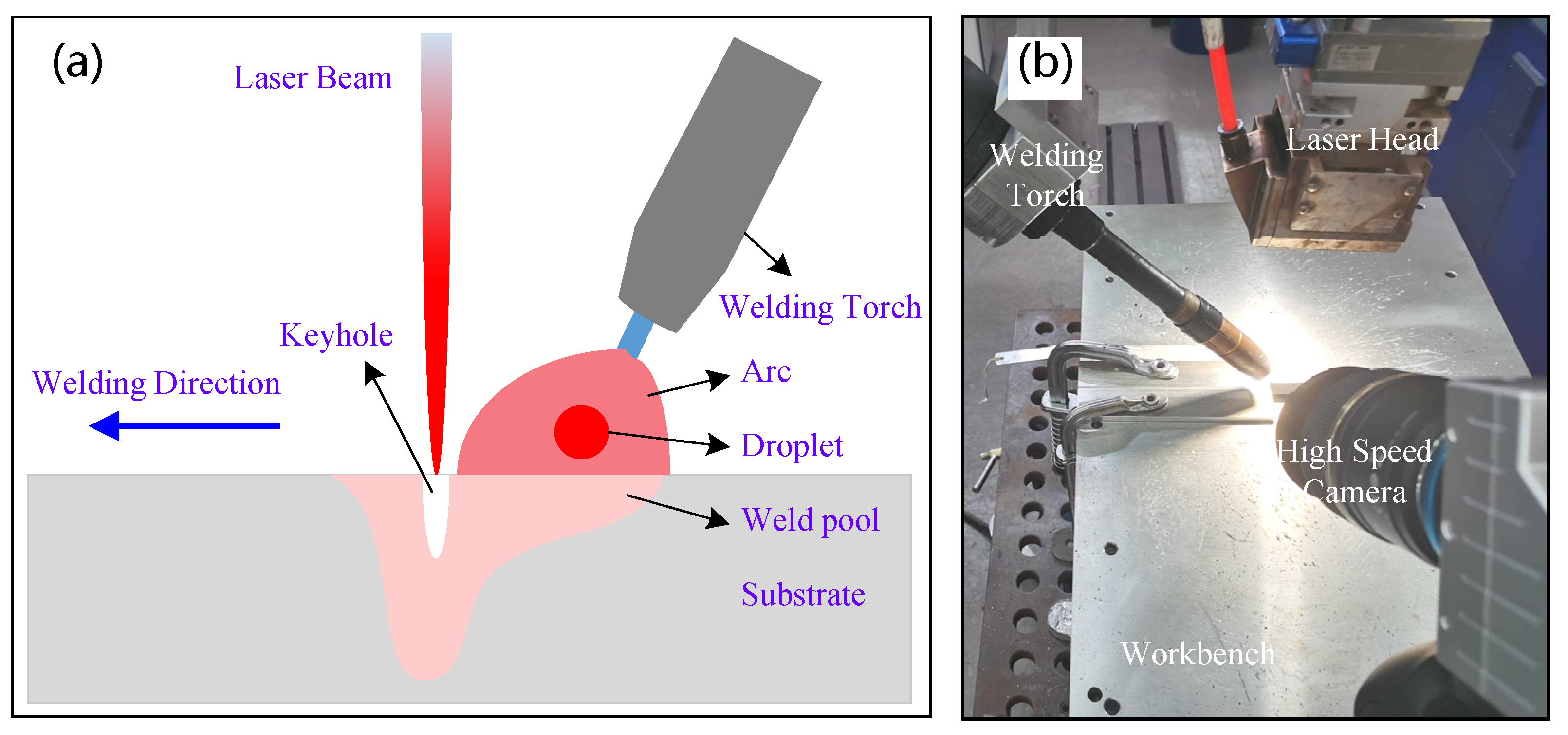
2.2. Characterization of Droplet Transfer and Porosity

The Acuteye high-speed camera system was adopted to observe the weld pool morphology and droplet transfer during the HLAW. The system is mainly composed of an optical lens (Nanjing, China), CoaXPress high-speed camera (Rocketech Technology, Changsha, China), PC storage system, CoaXPress coaxial cable, and laser. Before HLAW, a tripod was used to fix the camera on the top of the substrate, a clear image at the groove of the sample was found by focusing, and an auxiliary laser was used to adjust the aperture size. At the beginning of welding, the all-in-one machine is used for image capture, and then each frame of the image is exported and analyzed. The high-speed camera frequency is set to be 1000 Hz, i.e., every 1 millisecond to capture a picture. The image resolution is 1280 × 1024, and the frame rate is 1051 fps. A 200 kV nondestructive X-ray machine was used to characterize the porosity defects inside the weld.

3. Numerical Modeling

3.1. Model Simplification and Assumptions

The HLAW process involves physical processes such as material fusion, solidification, evaporation, and the interaction among solid, liquid, gas, and plasma [37,38]. Some aspects may lead to non-convergence of the model and can be neglected, and the following assumptions are considered in the model to achieve high computational efficiency:
(1)
The material is isotropic, and its liquid phase is incompressible Newtonian fluid in laminar flow mode;
(2)
The liquid region is assumed to be a porous medium with isotropic permeability;
(3)
The influence of shielding gas on the flow of weld pool and keyhole fluctuation is neglected;
(4)
The shielding effect and absorption effect of plasma on laser beam is neglected;
(5)
The calculation area of the weld pool and the keyhole is the symmetry of the weld;
(6)
The free surface of the weld pool is solved by the volume of fluid (VOF) equation in Equation (1).
F t + · ( u F ) = 0
where u is the fluid velocity, F is the volume fraction. In this model, aluminum alloy is the first phase, and plasma is the second phase. When F = 1, all control units are made of aluminum alloy.

3.2. Governing Equations

The modeling process of heat transfer, fluid flow, droplet transfer, and keyhole dynamic is described thoroughly in previous papers and not repeated here [39]. The thermophysical properties and related variables are displayed in Table 3.

3.2.1. Mass Conservation Equation

The regulation of mass conservation is one of the fundamental laws of nature. In any material system (isolated system) isolated from the surrounding, regardless of the change or process, its total mass remains unchanged. It is also called the continuity equation in the solution of the partial differential equation. Its premise is to adopt the continuous medium model for the fluid, and the velocity and density are continuous and differentiable functions of space coordinates and time. Mass conservation equation is defined as:
ρ t + ( ρ u ) x + ( ρ l ) y + ( ρ w ) z = S m
where ρ is the fluid density, u, l, w is the fluid velocity components in x, y, z directions, respectively. Sm is the source of mass, and the droplet transfer originated from adding filler wire during HLAW will increase the mass source Sm. Especially for incompressible fluids ρ t .

3.2.2. Energy Conservation Equation

The energy conservation equation is shown in Equation (3):
( ρ H ) t + ( ρ u H ) x + ( ρ l H ) y + ( ρ w H ) z = x ( λ T x ) + y ( λ T y ) + z ( λ T z ) + q n e t
where H is mixing enthalpy, T is temperature, λ is thermal conductivity, qnet is an external heat sources item in HLAW. During the HLAW process, there is not only the heat input from laser and arc but also the energy conversion of phase transformation and the heat loss of thermal radiation to the surrounding environment. The heat balance equation is shown in Equation (4):
q n e t = q A + q L + q D q E q R q C
where qA is energy from the arc; qL is energy from the laser; qE is heat loss of evaporation of metal vapor in the weld pool; qR is heat lost by thermal radiation; qC is heat loss due to heat exchange with the environment.

3.2.3. Momentum Conservation Equation

The momentum conservation equation is used to describe the motion equation of viscous incompressible fluid:
t ( ρ u ) + ρ ( u · ) u = p + η [ ( u + u T ) 2 3 u I ] + S m
where u = (u, l, w) represents the velocity component in the x, y, z directions, and Sm is the source term in the momentum conservation equation. The momentum originated from droplet transfer will increase the Sm term.

3.3. Model Validation

To ensure the reliability of the calculation results, HLAW experiments were carried out for verification, and the related process parameters were as follows: laser power is 4 kW; welding speed is 1.2 m/min; wire feeding rate is 5.3 m/min; arc current is 90 A; arc voltage is 18.6 V. The comparisons between the numerical simulations and experimental results are presented in Figure 2. The upper limit of temperature partition is set at 931 K, which is the liquidus temperature of 6061 aluminum alloy. The gray area in Figure 2 is the simulated geometry of the weld pool. Comparing the experimental results with the numerical simulations, the results suggested that the numerical model can guarantee the accuracy of simulation, which can be used for the subsequent simulation of temperature field and fluid flow of HLAW of 6 mm 6061 aluminum alloy.

4. Results and Discussion

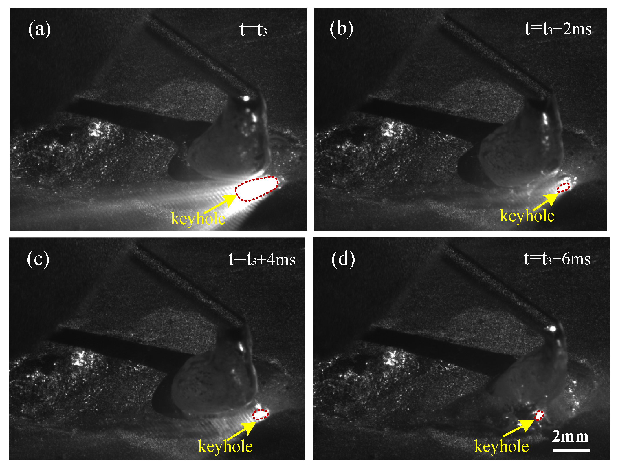
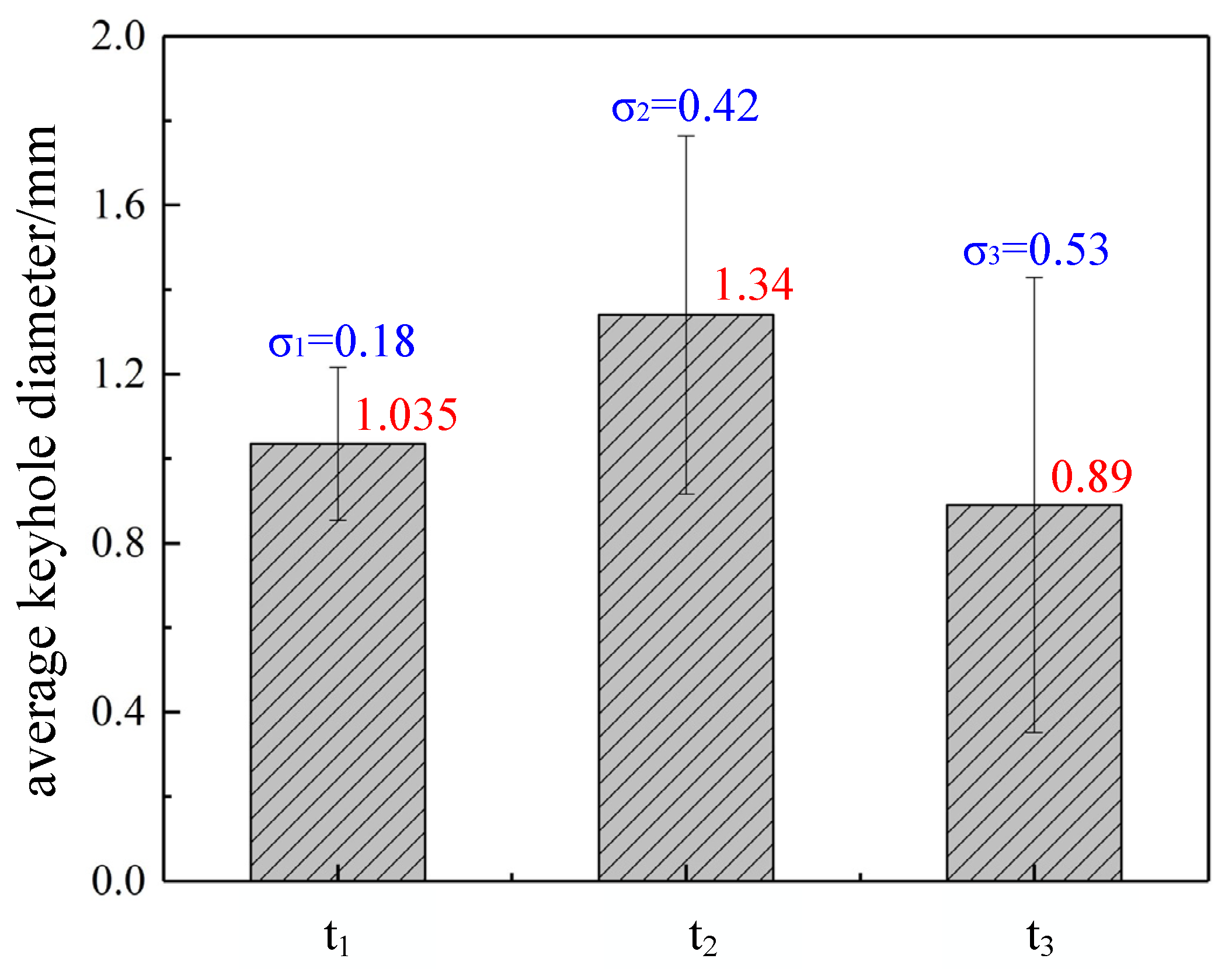
4.1. Experimental Observation of Droplet Transfer and Keyhole Fluctuation Behavior

Droplet transfer, weld pool evolution, and keyhole fluctuation during the HLAW process are displayed with a time interval of 2 milliseconds. The high-speed camera results of HLAW process with parameters of P = 4.0 kW, I = 90 A, v = 1.2 m/min are demonstrated and analyzed. Figure 3 shows experimentally observed keyhole fluctuation during the droplet growth stage. The bright spot with a red dotted line is the keyhole. The droplet gradually grows at the bottom of the welding wire during this stage. Experimental results suggest that keyhole size fluctuates slightly during this stage.
Figure 4 shows experimentally observed keyhole fluctuation before the droplet transfer stage. The diameter of the metal droplet is several times that of the filler wire during this stage. Due to the continuous heat accumulation effect by laser beam, the transverse-sectional area of the keyhole increases significantly compared with the previous stage. The metal droplet shakes driven by the comprehensive force of gravity, surface tension, shielding gas shear force, and plasma recoil pressure. As a result, the metal droplet has a particular shielding effect on the laser beam, which causes the fluctuation of the keyhole to become evident.
Figure 5 shows experimentally observed keyhole fluctuation during the droplet transfer stage. The droplet begins to shrink and separate from the filler wire during this stage. After the droplet contacts the upper surface of the weld pool, the liquid metal flows violently in the tangential direction of the weld pool driven by gravity. This phenomenon changes the fluid flow direction behind the keyhole from reverse keyhole direction to toward keyhole direction. Therefore, the transverse-sectional area of the keyhole decreases significantly compared with the previous stage. More laser energy is absorbed on the top surface of the weld pool instead of inside the weld pool, and keyhole penetration also decreases during this stage. Therefore, the periodic globular transfer has the most significant effect on keyhole fluctuation.
Quantitative analysis is conducted based on the keyhole dimension of the above three different stages, and the fluctuation of keyhole at different stages is compared in Figure 6. To avoid the shielding gas nozzle from the auxiliary laser, the high-speed camera is located above the substrate meaning that the keyhole photograph is elliptical. To diminish the measurement error, each keyhole is calculated by an average value of three times.
During the droplet growth stage, the average diameter of the keyhole is 1.035 mm, and the fluctuation range is slight. Before the droplet transfer stage, the average diameter of the keyhole reaches 1.34 mm, the keyhole fluctuates significantly, and its maximum diameter reaches 2.1 mm, which is conducive to the increase of keyhole depth. During the droplet transfer stage, the average diameter of the keyhole is 0.89 mm, the fluctuation range is the maximum, and the standard deviation of the keyhole transverse-section area is 0.53 mm. The following conclusions can be drawn by comparing the three stages of droplet transfer: the keyhole nearly keeps steady during the droplet growth stage; keyhole increases rapidly due to continuous heat accumulation before the droplet transfer stage; the keyhole fluctuates and decreases significantly due to liquid metal flowing toward the keyhole originated by globular transfer during the droplet transfer stage.

4.2. Numerical Simulation of Droplet Transfer and Keyhole Fluctuation Behavior

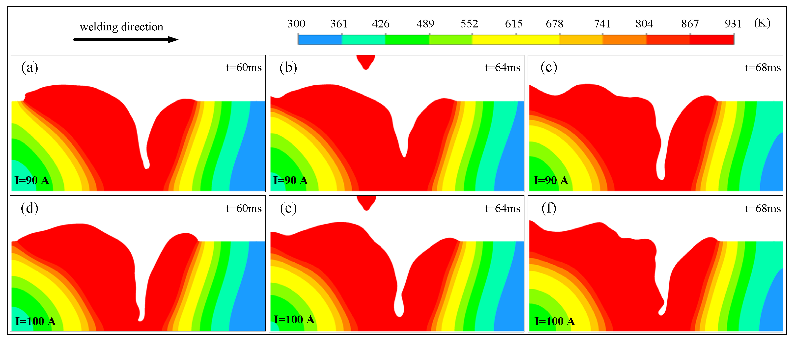
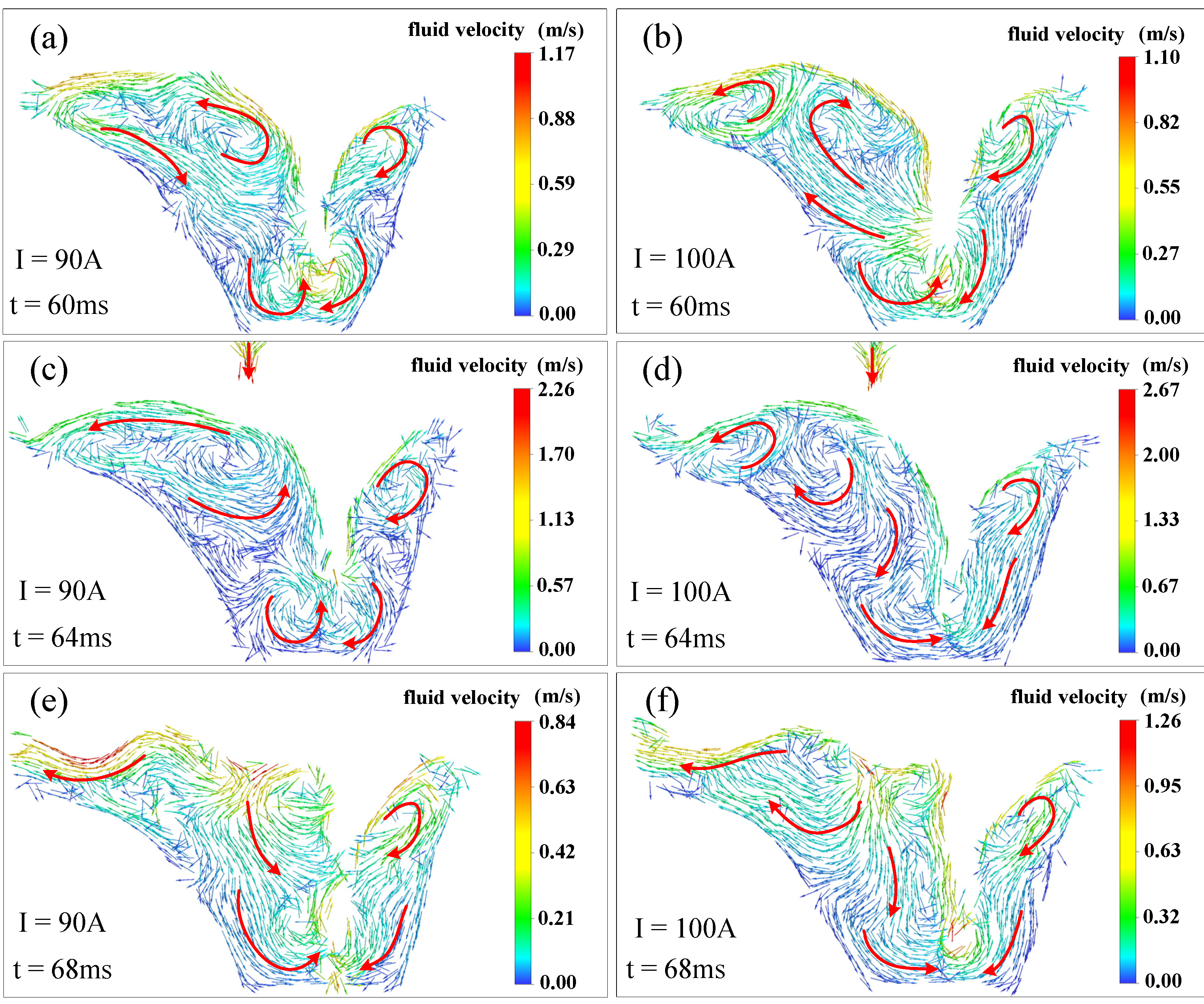
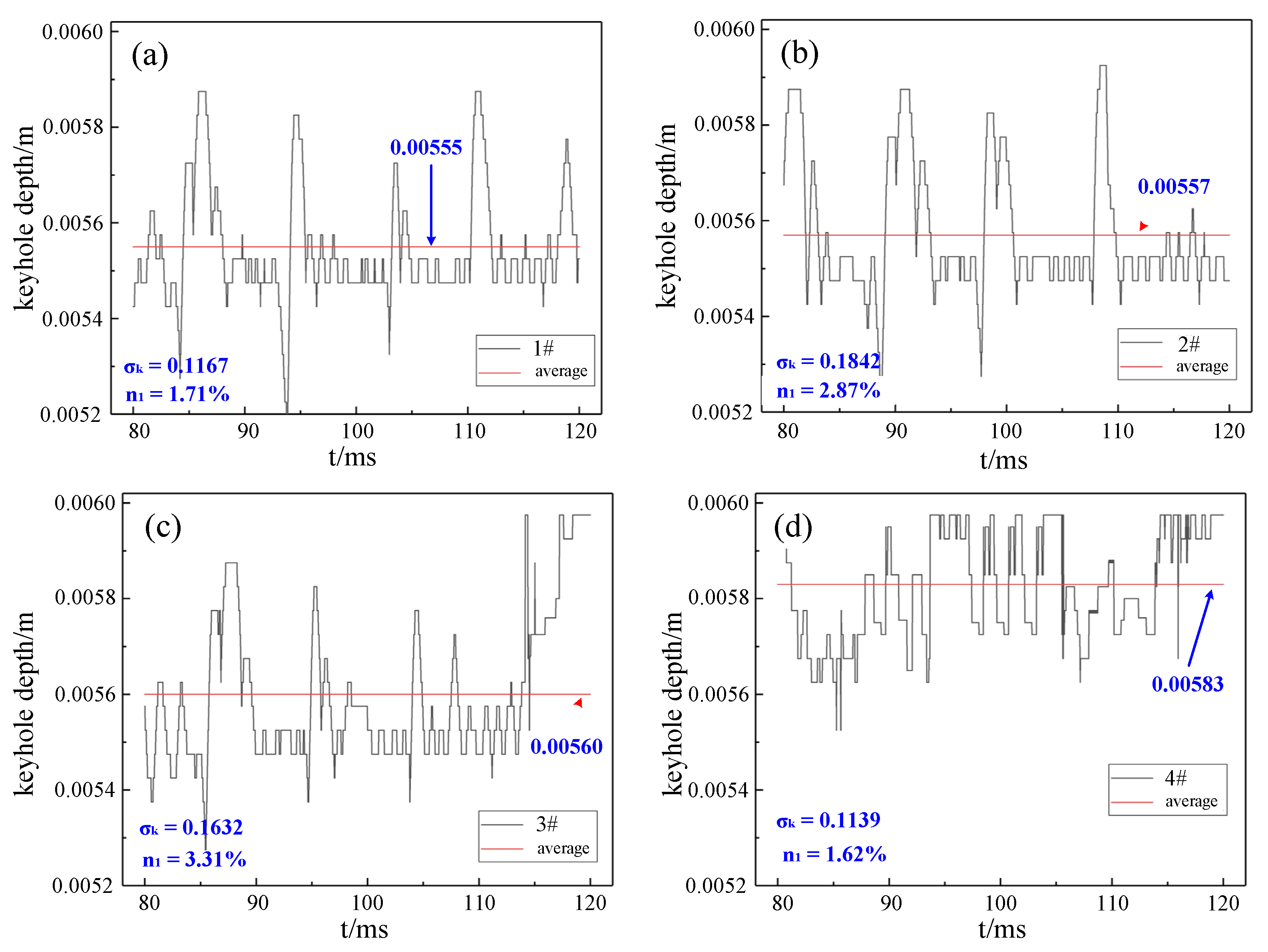
4.2.1. Influence of Welding Current on Keyhole Fluctuation Behavior

Figure 7 shows the temperature field distribution of the weld pool at different times under the process parameters of P = 4.5 kW, I = 90 A, v = 1.2 m/min and P = 4.5 kW, I = 100 A, v = 1.2 m/min. A screenshot of the temperature field simulation result is selected with a time interval of 4 milliseconds to show the temperature field distribution before and after droplet transfer. Both the trailing length and thickness of the weld pool increase with a higher arc current. However, the length of the lower part of the weld pool is nearly the same on the condition that the arc current is different. This is because of the wide and shallow heat effect of the arc heat source, while the laser energy dominates the bottom of the weld pool. For the parameter I = 90 A: when t = 60 milliseconds, the terminal of keyhole front wall and welding direction present an obtuse angle, which is unfavorable for the laser irradiating the bottom of the keyhole; when t = 64 milliseconds, the keyhole depth decreases, and the angle between keyhole front wall and welding direction is adjusted to an acute angle, which is conducive to the absorption of laser energy; when the droplet absolutely falls into the weld pool, the keyhole back wall has an acute angle with the welding direction. For the parameter of I = 100 A, the transverse-section area of the keyhole reaches the maximum at t = 64 millisecond, which is conducive to the input of laser energy to the bottom of the keyhole; when the droplet completely falls into the weld pool, a bulge appears on the back wall of the keyhole due to the impact force of the droplet, the energy input to the bottom of the keyhole decreases, and the keyhole depth decreases.
Figure 8 shows simulation results of fluid flow during the keyhole evolution process under different arc currents. Because of the metal vapor recoil pressure, the fluid flow on the keyhole wall is more intensive, and the fluid flows upward along the keyhole wall. The fluid behind the keyhole flows far away from the keyhole on the top surface of the weld pool driven by surface tension, which results in a long-tail type weld pool [42,43]. When I = 90 A, a counterclockwise vortex appears at the bottom of the keyhole back wall, which is conducive to the upward movement of the fluid along with the keyhole back wall. After the droplet ultimately falls into the weld pool, due to the impact effect of the droplet, the counterclockwise vortex in the middle area of the back of the weld pool disappears, and the fluid flows downward to the right, causing an impact on the back wall of the keyhole, and a bulge appears on the back wall of the keyhole. When t = 64 milliseconds, the maximum value of local fluid velocity in the lower part of the keyhole back wall reaches 2.26 m/s, and the direction is lower right, which accelerates the impact of fluid on the bottom of the keyhole and is conducive to the increase of keyhole depth. When I = 100 A, a clockwise eddy appears at the caudal of the weld pool, the eddy disappears after the droplet ultimately falls into the weld pool, and the fluid at the bottom of the keyhole circulates clockwise, and the local velocity reaches 1.26 m/s. The flow velocity of the weld pool is generally higher with higher arc power, and the surface area of the weld pool is wider with a higher flow velocity. Results suggest that the fluid flow velocity of the weld pool surface can be accelerated with a higher arc current.
The keyhole depth fluctuation curve under different arc currents is shown in Figure 9. Keyhole depth fluctuation can be divided into three stages: the duration of the first stage is almost the same, which is several milliseconds; the duration of the second and third stages are related to the arc current. In the first stage, the growth rate of keyhole depth is almost equal under different arc currents; in the second stage, the growth rate of keyhole oscillation with I = 100A fluctuates more, the growth rate is faster in 20–30 milliseconds, and then the growth rate decreases, and the fluctuation amplitude increases. It can be speculated that when the arc current increases, the amount of plasma above the weld pool increases, and the laser beam injected into the weld pool is absorbed and reflected, which leads to a significant fluctuation of keyhole depth. During the HLAW process, the laser heat source and the arc heat source act on the weld pool simultaneously, and the interaction has an apparent relationship with the arc current, so the arc current has a significant influence on the keyhole depth reaching the stationary stage.

4.2.2. Influence of Welding Speed on Keyhole Fluctuation Behavior

Figure 10 shows the temperature field distribution of weld pool at different times under the process parameters of P = 4.0 kW, I = 90 A, v = 1.5 m/min and P = 4.0 kW, I = 90 A, v = 1.2 m/min. A screenshot of the temperature field simulation result is selected with a time interval of 4 milliseconds to show the temperature field distribution before and after droplet transfer. The welding speed affects the heat input of laser energy and arc energy so that it has an important influence on the distribution of temperature field and fluid flow. The trailing length at the back of the laser focus point increases with lower welding speed, which is mainly due to the decrease of energy input into the weld pool. For the two groups of parameters, when t = 64 milliseconds, a bubble forms at the bottom of the weld pool, mainly because the bottom of the keyhole is blocked by the liquid bridge and becomes a bubble surrounded by liquid metal. When t = 68 milliseconds, the keyhole depth increases, but there is still a small bubble at the bottom of the keyhole with v = 1.5 m/min. Under the influence of droplet transfer, the angle between the keyhole back wall and welding direction changes from obtuse angle to acute angle. For v = 1.2 m/min, when t = 68 milliseconds, the keyhole back wall appears to bulge under the influence of droplet impact, which affects the laser irradiation into the keyhole to a certain extent. The instability of the keyhole is related to the bulge on the keyhole wall, and the thermo-capillary force of the weld pool and welding speed will affect the formation of a bulge on the keyhole wall.
Figure 11 shows the simulation results of fluid flow during the keyhole evolution process under different welding speeds. Because of the metal vapor recoil pressure on the keyhole wall, the fluid flow in the weld pool becomes more intense, and the velocity at the bottom of the keyhole increases. The front liquid metal of the weld pool flows upward along the front wall of the keyhole, the counterclockwise eddy appears at the tail of the weld pool. A clockwise eddy is generated around the bubble at the bottom of the keyhole due to the liquid bridge partition; the weak liquid bridge moves up along the keyhole wall. When t = 68 milliseconds, the liquid bridge disappears, and the bubble and keyhole form a deeper keyhole.
For v = 1.5 m/min, a counterclockwise vortex appears in the middle of the trailing part of the weld pool, which is conducive to the fluid flow to the back of the weld pool and increases the volume of the weld pool. When t = 64 milliseconds and t = 68 milliseconds, the fluid velocity at the bottom of the keyhole front wall is maximum, and there is a downward velocity component, which is conducive to the increase of keyhole depth. For v = 1.2 m/min, when the droplet ultimately falls into the weld pool, the upward velocity of the fluid along with the keyhole back wall increases, and the backward velocity of the weld pool tail increases. When the welding speed is low, it is easy to form a counterclockwise eddy at the back of the weld pool. When the welding speed is high, the flow direction of the fluid at the bottom of the keyhole is from front to back, which is conducive to the increase of the volume at the back of the weld pool.
Comparing the keyhole depth fluctuation of different welding speeds under a small arc current, the keyhole depth fluctuation curve under two groups of parameters is shown in Figure 12. In the first stage, the time length and keyhole growth rate are almost identical, both in a few milliseconds; the second and third stages are related to the welding speed. The keyhole with v = 1.2 m/min reaches a stable condition about 4 milliseconds ahead of time.
Figure 13 shows the internal porosity of hybrid laser arc welds with different welding speeds. Results from X-ray nondestructive testing indicate that weld with v = 1.2 m/min parameters contain more pores. The pore number of welds with v = 1.2 m/min is more uniform and intensive, while the pore number of welds with v = 1.5 m/min was significantly reduced. The maximum diameter and average diameter of the pores in the weld increase significantly with lower welding speed. The experimental results show good agreement with the previous simulation analysis.

4.3. Relationship between Keyhole Fluctuation and Weld Porosity

The above analysis indicates that the existence of the keyhole has an important influence on the bubble escape. The rapid fluid flow of the keyhole wall can quickly bring the bubble out of the weld pool, and the process porosity at the bottom of the keyhole due to liquid bridge partition has an essential relationship with the stability of the keyhole. Based on the simulation results of keyhole depth stability and the porosity measured from the experimental results, the simulation results of keyhole depth variation from 80 milliseconds to 120 milliseconds are selected for analysis. Table 4 shows statistical data of keyhole steady-state fluctuation and porosity rate with different process parameters. The following are the keyhole depth statistics of the first group to the fourth group in the steady-state fluctuation stage, and the average values are 5.55, 5.57, 5.60, and 5.84 mm, respectively. The difference between the maximum and minimum keyhole depth is 0.90, 0.84, 0.91, and 0.40 mm, respectively. According to the above-mentioned X-ray nondestructive testing results, the porosity in the weld is 1.71%, 2.87%, 3.31%, and 1.62%, respectively.
Figure 14 shows the variation of keyhole depth in the steady-state fluctuation stage, and the standard deviation table of keyhole depth variation is σk. The time stage of 80–120 milliseconds is selected to analyze the steady-state fluctuation stage of the keyhole with selected parameters. The average value of keyhole depth is almost the same as the thickness of the plate in the range of 5.55–5.84 mm. When the standard deviation of keyhole steady-state fluctuation is between 0.11–0.12, the range of keyhole depth is small, and the keyhole achieves better stability, the corresponding porosity rate value is about 1.7%. When the standard deviation of keyhole steady-state fluctuation is between 0.16 and 0.18, the keyhole depth range is larger, and the corresponding porosity rate is about 3%. During the keyhole laser welding model, the keyhole tends to become unstable with a higher aspect ratio [36]. In other words, the keyhole depth fluctuation results in fluctuation of aspect ratio, which further leads to worse keyhole stability. Compared with the results of the 3rd and 4th groups as well as the 1st and 2nd groups, results indicated that porosity rate is nearly positively correlated with the keyhole depth variation. Compared with the results of the 2nd and the 3rd group, the increase of arc current in a specific range is unfavorable to maintaining the stability of the keyhole.

5. Conclusions

The droplet transfer, weld pool evolution, and keyhole fluctuation behavior process during HLAW are modeled and simulated. The simulation results of temperature field, fluid flow, and keyhole fluctuation under different welding process parameters are analyzed. The following conclusions can be drawn:
(1)
Droplet transfer has an important influence on keyhole morphology. Droplet transfer changes the temperature field and fluid flow of the weld pool due to its external mass, heat, and momentum. Keyhole fluctuation and keyhole diameter presents different features during different stages of droplet transfer. Keyhole caliber becomes minimum and sometimes collapses when the droplet contacts the weld pool. Keyhole size is small with slight fluctuation during the droplet growth stage; keyhole size is larger with significant fluctuation before the droplet transfer stage; keyhole fluctuation becomes severe during the droplet transfer stage.
(2)
During the droplet transfer stage, liquid metal on the top surface of the weld pool flows toward the keyhole originated by globular transfer, keyhole fluctuates and decreases significantly, which has a higher tendency to form a bubble in the weld pool. The bubble evolves into porosity once trapped in the mush-zone near the trailing edge of the weld pool.
(3)
Welding current has a significant influence on keyhole stability fluctuation and weld porosity. Droplet transfer frequency, keyhole fluctuation, and porosity rate increase with higher welding current under the globular transfer mode. The keyhole depth fluctuation results in fluctuation of aspect ratio, which further leads to worse keyhole stability. The porosity rate shows a nearly positive correlation with the standard deviation of keyhole fluctuation.

Author Contributions

Conceptualization, L.W. and X.Z.; methodology, Y.Z. and Y.L.; software, L.W. and Y.Z.; investigation, L.W.; writing—original draft preparation, L.W. and Y.L.; writing—review and editing, L.W. All authors have read and agreed to the published version of the manuscript.

Funding

This research was funded by the Fundamental Research Funds for the Central Universities, grant number NS2021045.

Data Availability Statement

Not applicable.

Conflicts of Interest

The authors declare no conflict of interest.

References

  1. Oliveira, J.P.; Shen, J.; Zeng, Z.; Park, J.M.; Choi, Y.T.; Schell, N.; Maawad, E.; Zhou, N.; Kim, H.S. Dissimilar laser welding of a CoCrFeMnNi high entropy alloy to 316 stainless steel. Scr. Mater. 2022, 206, 114219. [Google Scholar] [CrossRef]
  2. Oliveira, J.P.; Shen, J.; Escobar, J.D.; Salvador, C.A.F.; Schell, N.; Zhou, N.; Benafan, O. Laser welding of H-phase strengthened Ni-rich NiTi-20Zr high temperature shape memory alloy. Mater. Des. 2021, 202, 109533. [Google Scholar] [CrossRef]
  3. Oliveira, J.P.; Crispim, B.; Zeng, Z.; Omori, T.; Braz Fernandes, F.M.; Miranda, R.M. Microstructure and mechanical properties of gas tungsten arc welded Cu-Al-Mn shape memory alloy rods. J. Mater. Process. Technol. 2019, 271, 93–100. [Google Scholar] [CrossRef]
  4. Cunningham, R.; Zhao, C.; Parab, N.; Kantzos, C.; Pauza, J.; Fezzaa, K.; Sun, T.; Rollett, A.D. Keyhole threshold and morphology in laser melting revealed by ultrahigh-speed x-ray imaging. Science 2019, 363, 849. [Google Scholar] [CrossRef]
  5. Geng, S.; Jiang, P.; Shao, X.; Guo, L.; Gao, X. Heat transfer and fluid flow and their effects on the solidification microstructure in full-penetration laser welding of aluminum sheet. J. Mater. Sci. Technol. 2020, 46, 50–63. [Google Scholar] [CrossRef]
  6. Wang, L.; Xue, J.; Wang, Q. Correlation between arc mode, microstructure, and mechanical properties during wire arc additive manufacturing of 316L stainless steel. Mater. Sci. Eng. A 2019, 751, 183–190. [Google Scholar] [CrossRef]
  7. Chen, X.; Yu, G.; He, X.; Li, S. Investigation of thermal dynamics for different leading configuration in hybrid laser-MIG welding. Opt. Laser Technol. 2021, 134, 106567. [Google Scholar] [CrossRef]
  8. Xu, X.; Song, G.; Zhao, S.; Liu, L. Effect of distance between the heat sources on energy transfer behavior in keyhole during laser-GTA welding titanium alloy. J. Manuf. Process. 2020, 55, 317–325. [Google Scholar] [CrossRef]
  9. Ragavendran, M.; Vasudevan, M. Laser and hybrid laser welding of type 316L(N) austenitic stainless steel plates. Mater. Manuf. Process. 2020, 35, 922–934. [Google Scholar] [CrossRef]
  10. Gao, Z. Numerical modeling to understand liquation cracking propensity during laser and laser hybrid welding (I). Int. J. Adv. Manuf. Technol. 2012, 63, 291–303. [Google Scholar] [CrossRef]
  11. Chen, Y.; Feng, J.; Li, L.; Chang, S.; Ma, G. Microstructure and mechanical properties of a thick-section high-strength steel welded joint by novel double-sided hybrid fibre Laser arc welding. Mater. Sci. Eng. A 2013, 582, 284–293. [Google Scholar] [CrossRef]
  12. Zhang, C.; Gao, M.; Li, G.; Chen, C.; Zeng, X.Y. Strength improving mechanism of laser arc hybrid welding of wrought AA 2219 aluminium alloy using AlMg5 wire. Sci. Technol. Weld. Join. 2013, 18, 703–710. [Google Scholar] [CrossRef]
  13. Tang, G.; Zhao, X.; Li, R.; Liang, Y.; Jiang, Y.; Chen, H. Microstructure and properties of Laser arc hybrid welding thick bainitic steel joints with different arc position. Mater. Res. Express 2019, 6, 076547. [Google Scholar] [CrossRef]
  14. Russo Spena, P.; Angelastro, A.; Casalino, G. Hybrid laser arc welding of dissimilar TWIP and DP high strength steel weld. J. Manuf. Process. 2019, 39, 233–240. [Google Scholar] [CrossRef]
  15. Hammad, A.; Churiaque, C.; Sánchez-Amaya, J.M.; Abdel-Nasser, Y. Experimental and numerical investigation of hybrid laser arc welding process and the influence of welding sequence on the manufacture of stiffened flat panels. J. Manuf. Process. 2021, 61, 527–538. [Google Scholar] [CrossRef]
  16. Subashini, L.; Prabhakar, K.V.P.; Ravi, C.G.; Swati, G.; Padmanabham, G. Single Pass Laser Arc Hybrid Welding of Maraging Steel Thick Sections. Mater. Manuf. Process. 2016, 31, 2186–2198. [Google Scholar] [CrossRef]
  17. Kang, K.; Kawahito, Y.; Gao, M.; Zeng, X. Effects of Laser arc distance on corrosion behavior of single-pass hybrid welded stainless clad steel plate. Mater. Des. 2017, 123, 80–88. [Google Scholar] [CrossRef]
  18. Blecher, J.J.; Palmer, T.A.; DebRoy, T. Mitigation of Root Defect in Laser and Hybrid Laser Arc Welding. Weld. J. 2015, 94, 73S–82S. [Google Scholar]
  19. Mazar Atabaki, M.; Ma, J.; Liu, W.; Kovacevic, R. Pore formation and its mitigation during hybrid laser/arc welding of advanced high strength steel. Mater. Des. 2015, 67, 509–521. [Google Scholar] [CrossRef]
  20. Zhang, L.-J.; Bai, Q.-L.; Ning, J.; Wang, A.; Yang, J.-N.; Yin, X.-Q.; Zhang, J.-X. A comparative study on the microstructure and properties of copper joint between MIG welding and laser-MIG hybrid welding. Mater. Des. 2016, 110, 35–50. [Google Scholar] [CrossRef]
  21. He, C.; Huang, C.; Liu, Y.; Li, J.; Wang, Q. Effects of mechanical heterogeneity on the tensile and fatigue behaviours in a Laser arc hybrid welded aluminium alloy joint. Mater. Des. 2015, 65, 289–296. [Google Scholar] [CrossRef]
  22. Wang, P.; Chen, X.; Pan, Q.; Madigan, B.; Long, J. Laser welding dissimilar materials of aluminum to steel: An overview. Int. J. Adv. Manuf. Technol. 2016, 87, 3081–3090. [Google Scholar] [CrossRef]
  23. You, D.; Gao, X.; Katayama, S. Monitoring of high-power laser welding using high-speed photographing and image processing. Mech. Syst. Signal Proc. 2014, 49, 39–52. [Google Scholar] [CrossRef]
  24. Ribic, B.; Rai, R.; DebRoy, T. Numerical simulation of heat transfer and fluid flow in GTA/Laser hybrid welding. Sci. Technol. Weld. Join. 2008, 13, 683–693. [Google Scholar] [CrossRef]
  25. Ribic, B.; Palmer, T.A.; DebRoy, T. Problems and issues in Laser arc hybrid welding. Int. Mater. Rev. 2009, 54, 223–244. [Google Scholar] [CrossRef]
  26. Blecher, J.J.; Palmer, T.A.; Debroy, T. Porosity in thick section alloy 690 welds–experiments, modeling, mechanism, and remedy. Weld. J. 2016, 95, 17–26. [Google Scholar]
  27. Wang, C.M.; Mi, G.Y.; Zhang, X. Welding stability and fatigue performance of laser welded low alloy high strength steel with 20 mm thickness. Opt. Laser Technol. 2021, 139, 106941. [Google Scholar] [CrossRef]
  28. Cai, W.; Wang, J.Z.; Cao, L.C.; Mi, G.Y.; Shu, L.S.; Zhou, Q.; Jiang, P. Predicting the weld width from high-speed successive images of the weld zone using different machine learning algorithms during laser welding. Math. Biosci. Eng. 2019, 16, 5595–5612. [Google Scholar] [CrossRef] [PubMed]
  29. Bunaziv, I.; Akselsen, O.M.; Salminen, A.; Unt, A. Fiber laser-MIG hybrid welding of 5mm 5083 aluminum alloy. J. Mater. Process. Technol. 2016, 233, 107–114. [Google Scholar] [CrossRef]
  30. Zhan, X.; Zhao, Y.; Liu, Z.; Gao, Q.; Bu, H. Microstructure and porosity characteristics of 5A06 aluminum alloy joints using laser-MIG hybrid welding. J. Manuf. Process. 2018, 35, 437–445. [Google Scholar] [CrossRef]
  31. Zhao, Y.; Zhan, X.; Gao, Q.; Chen, S.; Kang, Y. Research on the Microstructure Characteristic and Tensile Property of Laser-MIG Hybrid Welded Joint for 5A06 Aluminum Alloy. Met. Mater. Int. 2020, 26, 346–359. [Google Scholar] [CrossRef]
  32. Ke, W.; Bu, X.; Oliveira, J.P.; Xu, W.; Wang, Z.; Zeng, Z. Modeling and numerical study of keyhole-induced porosity formation in laser beam oscillating welding of 5A06 aluminum alloy. Opt. Laser Technol. 2021, 133, 106540. [Google Scholar] [CrossRef]
  33. Lu, F.; Li, X.; Li, Z.; Tang, X.; Cui, H. Formation and influence mechanism of keyhole-induced porosity in deep-penetration laser welding based on 3D transient modeling. Int. J. Heat Mass Transf. 2015, 90, 1143–1152. [Google Scholar] [CrossRef]
  34. Zhang, D.; Wei, Y.H.; Zhan, X.H.; Chen, J.; Li, H.; Wang, Y.H. Numerical simulation of keyhole behaviors and droplet transfer in laser-MIG hybrid welding of Invar alloy. Int. J. Numer. Methods Heat Fluid Flow 2018, 28, 1974–1993. [Google Scholar] [CrossRef]
  35. Xu, G.; Li, L.; Wang, H.; Li, P.; Guo, Q.; Hu, Q.; Du, B. Simulation and experimental studies of keyhole induced porosity in laser-MIG hybrid fillet welding of aluminum alloy in the horizontal position. Opt. Laser Technol. 2019, 119, 105667. [Google Scholar] [CrossRef]
  36. Gan, Z.; Kafka, O.L.; Parab, N.; Zhao, C.; Fang, L.; Heinonen, O.; Sun, T.; Liu, W.K. Universal scaling laws of keyhole stability and porosity in 3D printing of metals. Nat. Commun. 2021, 12, 2379. [Google Scholar] [CrossRef] [PubMed]
  37. Chongbunwatana, K. Simulation of vapour keyhole and weld pool dynamics during laser beam welding. Prod. Eng. 2014, 8, 499–511. [Google Scholar] [CrossRef]
  38. Gu, X.; Li, H.; Jiang, X.; Sheng, H.; Wan, X. Effect of laser on droplet transfer and welding process stability in hybrid laser + double arc welding. Int. J. Adv. Manuf. Technol. 2016, 89, 2981–2991. [Google Scholar] [CrossRef]
  39. Li, Y.; Zhao, Y.; Zhou, X.; Zhan, X. Effect of Droplet Transition on the Dynamic Behavior of the Keyhole during 6061 Aluminum Alloy Laser-MIG Hybrid Welding. Int. J. Adv. Manuf. Technol. 2021. [Google Scholar] [CrossRef]
  40. Wang, L.L.; Wei, H.L.; Xue, J.X.; DebRoy, T. A pathway to microstructural refinement through double pulsed gas metal arc welding. Scr. Mater. 2017, 134, 61–65. [Google Scholar] [CrossRef]
  41. Rao, Z.H.; Liu, J.W.; Wang, P.C.; Li, Y.X.; Liao, S.M. Modeling of Cold Metal Transfer Spot Welding of AA6061-T6 Aluminum Alloy and Galvanized Mild Steel. J. Manuf. Sci. Eng. 2014, 136, 051001. [Google Scholar] [CrossRef]
  42. Guoxiang, X.; Wu, C.; Ma, X.; Wang, X. Numerical Analysis of Welding Residual Stress and Distortion in Laser+GMAW Hybrid Welding of Aluminum Alloy T-Joint. Acta Metall. Sin.-Engl. Lett. 2013, 26, 352–360. [Google Scholar]
  43. Wang, L.L.; Wei, H.L.; Xue, J.X.; DebRoy, T. Special features of double pulsed gas metal arc welding. J. Mater. Process. Technol. 2018, 251, 369–375. [Google Scholar] [CrossRef]
Figure 1. (a) Schematic diagram of hybrid laser arc welding; (b) Experimental setup.
Metals 11 01510 g001
Figure 2. Comparisons between the experimental and numerical simulated weld transverse-section geometry.
Metals 11 01510 g002
Figure 3. Experimentally observed keyhole fluctuation during the droplet growth stage. (a) t = t1; (b) t = t1 + 2 ms; (c) t = t1 + 4 ms; (d) t = t1 + 6 ms.
Metals 11 01510 g003
Figure 4. Experimentally observed keyhole fluctuation before the droplet transfer stage. (a) t = t2; (b) t = t2 + 2 ms; (c) t = t2 + 4 ms; (d) t = t2 + 6 ms.
Metals 11 01510 g004
Figure 5. Experimentally observed keyhole fluctuation during the droplet transfer stage. (a) t = t3; (b) t = t3 + 2 ms; (c) t = t3 + 4 ms; (d) t = t3 + 6 ms.
Metals 11 01510 g005
Figure 6. Average keyhole diameter and standard deviation during different stages.
Metals 11 01510 g006
Figure 7. Simulation results of temperature field in keyhole evolution process under different arc currents. (ac) I = 90 A; (df) I = 100 A.
Metals 11 01510 g007
Figure 8. Simulation results of fluid flow during keyhole evolution process under different arc currents. (a,c,e) I = 90 A; (b,d,f) I = 100 A.
Metals 11 01510 g008
Figure 9. Keyhole depth fluctuation under different arc currents. (a) I = 90 A; (b) I = 100 A.
Metals 11 01510 g009
Figure 10. Simulation results of temperature field in keyhole evolution process under different welding current. (ac) v = 1.5 m/min; (df) v = 1.2 m/min.
Metals 11 01510 g010
Figure 11. Simulation results of fluid flow during keyhole evolution process under different welding speed. (a,c,e) v = 1.5 m/min; (b,d,f) v = 1.2 m/min.
Metals 11 01510 g011
Figure 12. Keyhole depth fluctuation under different welding speeds. (a) v = 1.5 m/min; (b) v = 1.2 m/min.
Metals 11 01510 g012
Figure 13. Internal porosity of weld with different welding speeds. (a) P = 4.0 kW, I = 90 A, v =1.5 m/min; (b) P = 4.0 kW, I = 90 A, v = 1.2 m/min.
Metals 11 01510 g013
Figure 14. Variation diagram of keyhole depth in steady-state fluctuation stage. (a) P = 4.0 kW, I = 90 A, v = 1.5 m/min; (b) P = 4.0 kW, I = 90 A, v = 1.2 m/min; (c) P = 4.0 kW, I = 100 A, v = 1.2 m/min; (d) P = 4.0 kW, I = 100 A, v = 1.0 m/min.
Metals 11 01510 g014
Table 1. Chemical compositions of 6061 aluminum alloy (wt.%).
MaterialsSiFeCuMnMgZnTiCrAl
AA60610.4–0.80.70.15–0.40.150.8–1.20.250.150.04–0.35Bal.
ER4047120.80.030.150.10.20.00250.05Bal.
Table 2. Process parameters during hybrid laser arc welding.
CaseLaser Power
(kW)
Welding Speed
(m/min)
Welding Current
(A)
Arc Voltage
(V)
Wire Feeding Rate
(m/min)
14.51.29012.65.3
24.51.210012.95.7
34.01.59012.65.3
44.01.29012.65.3
Table 3. Thermo-physical properties of 6061 aluminum alloy for simulation [40,41].
Physical PropertySymbolValueUnit
Mass densityρ2630Kg/m3
Thermal expansion coefficientβ3.02 × 10−51/K
Heat conductivityλ204W/(m·K)
Solid temperatureTm858.13K
Liquid temperatureTl923.15K
Evaporation temperatureTb2790K
Latent heat of fusionLm5.03 × 105J/kg
Latent heat of evaporationLv1.07 × 107J/kg
Specific heat capacity of solidCp900J/(kg·K)
Specific heat capacity of liquidCl1200J/(kg·K)
Surface tensionσ0.99N/m
Temperature coefficient of surface tension−1.3 × 10⁻⁴N/(m·K)
Dynamic viscosityη0.0045Pa·s
Surface emissivityε0.1N/A
Ambient temperatureTref300K
Magnetic permeabilityμ1.26 × 10⁻⁶H/m
Table 4. Statistical data of keyhole steady-state fluctuation and porosity rate with different process parameters.
CaseLaser Power
(kW)
Welding Current
(A)
Welding Speed
(m/min)
Average Keyhole Depth
(mm)
Standard DeviationPorosity Rate
(%)
Range of Keyhole Depth
(mm)
14.0901.55.460.11671.710.90
24.0901.25.570.18422.870.84
34.01001.25.600.16323.310.91
44.01001.05.830.11391.620.40
Publisher’s Note: MDPI stays neutral with regard to jurisdictional claims in published maps and institutional affiliations.

