
An Approach to Reduce Thermal Damages on Grinding of Bearing Steel by Controlling Cutting Fluid Temperature


Abstract
1. Introduction
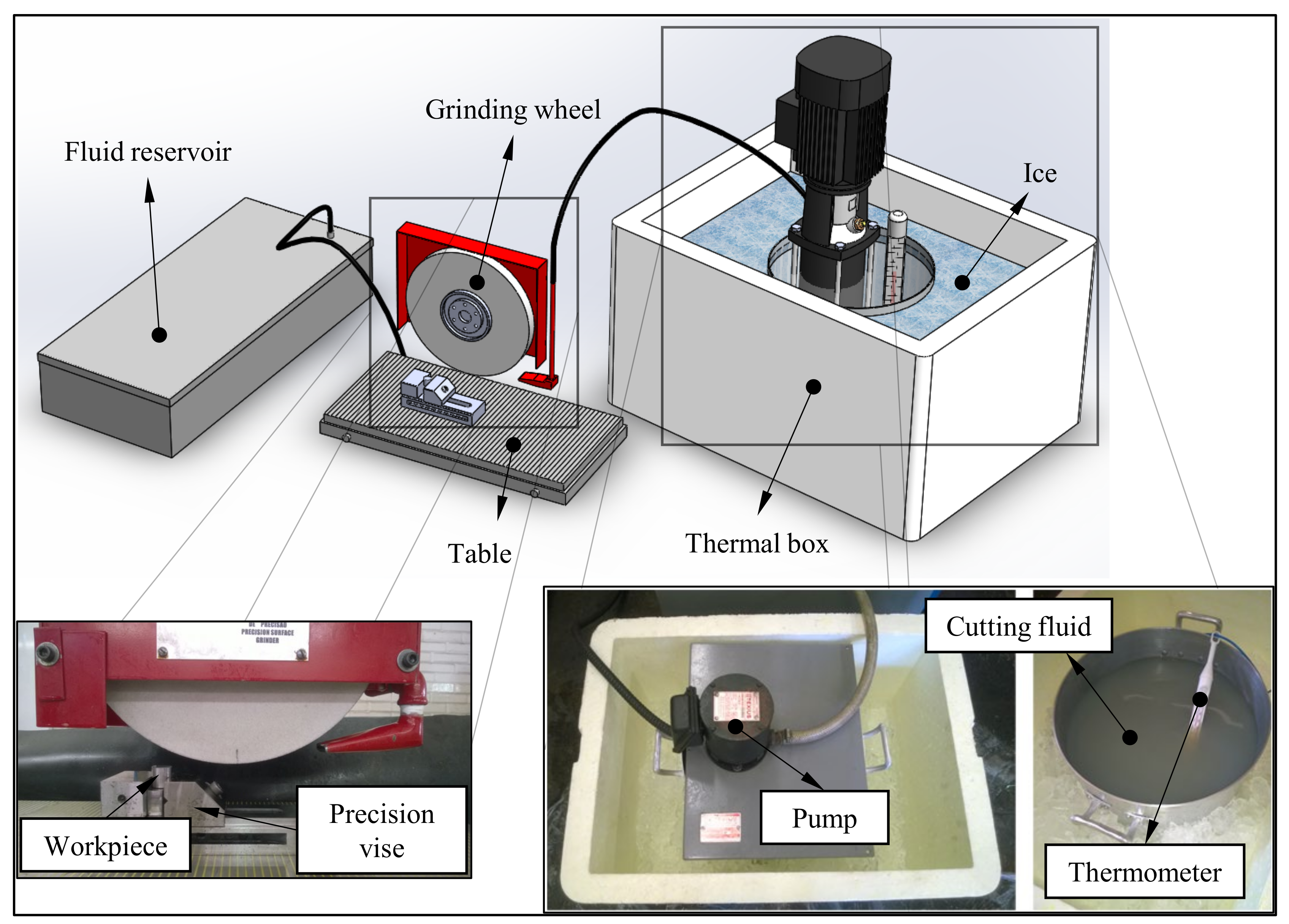
2. Materials and Methods
3. Results and Discussion
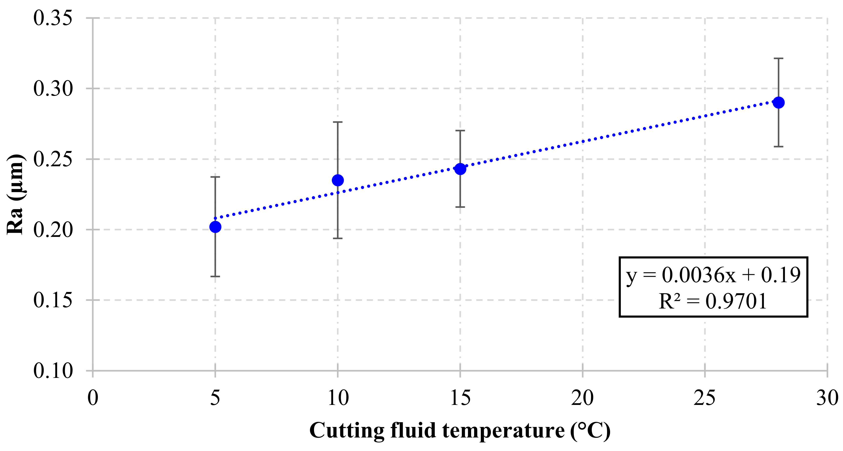
3.1. Surface Roughness
3.2. Images of Machined Surfaces
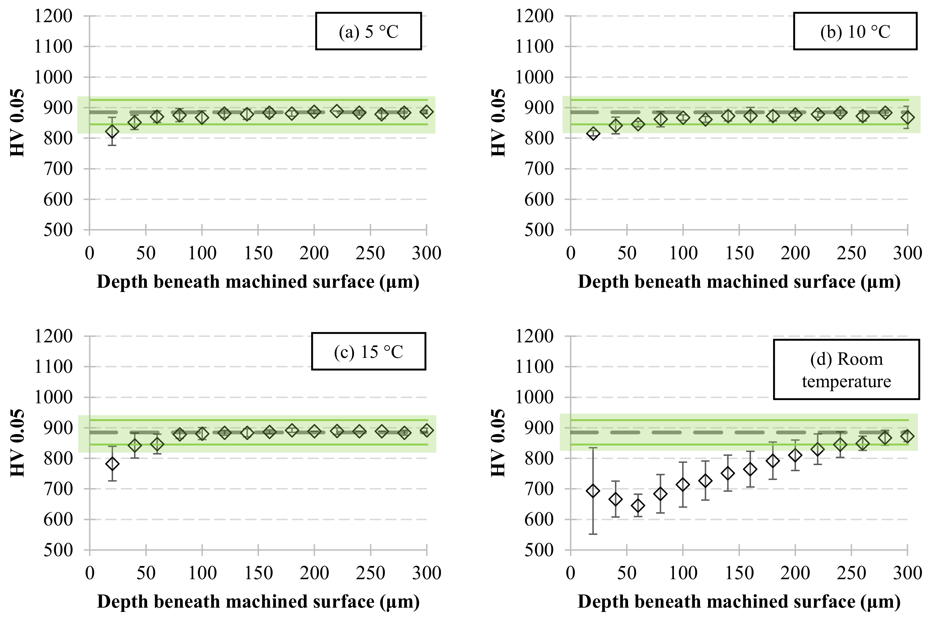
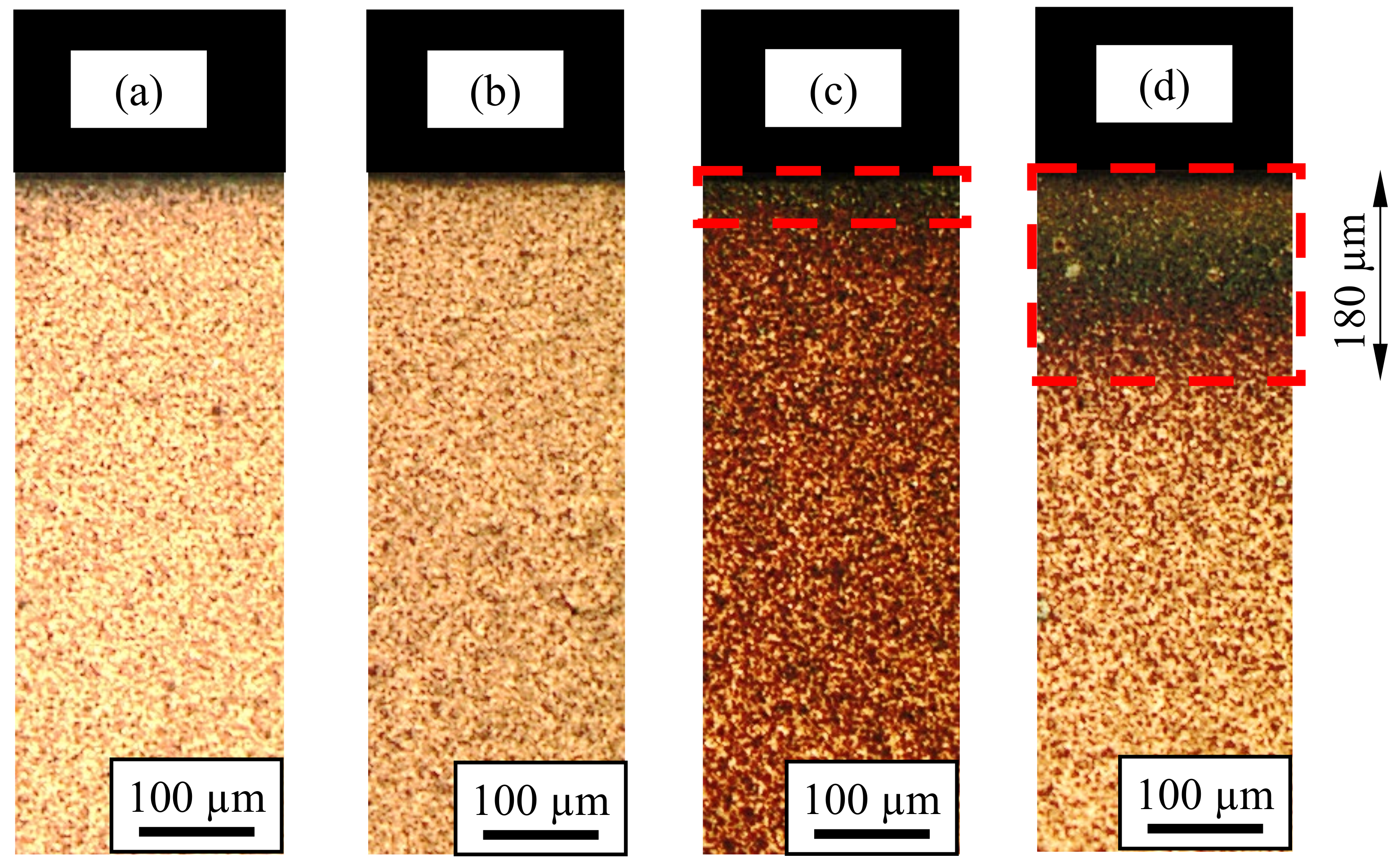
3.3. Microhardness and Microstructure Beneath the Machined Surface
4. Conclusions
- Although usually neglected in research papers concerning conventional cutting fluid applications (flood) in grinding, the temperature of the cutting fluid in the instant of its application strongly affected the workpiece surface integrity. Controlling this parameter at low levels (5–15 °C) contributed to the improved surface quality of the workpiece, especially for the lowest cutting fluid temperature (5 °C), which promoted a 31% reduction in Ra roughness in comparison to the cutting fluid at room temperature (28 ± 1 °C).
- No visible workpiece burn was observed on the ground surface after grinding with cutting fluid at low temperatures (5–15 °C)—only when grinding with the cutting fluid at room temperature.
- Controlling the cutting fluid temperature at low levels (5–15 °C) reduced the extension of hardness reduction beneath the round surface to 92% in comparison to the grinding with cutting fluid at room temperature (28 ± 1 °C). Furthermore, the thickness of the over-tempered region (dark layer) beneath the machined surface was significantly reduced by applying the cutting fluid with temperature at low levels.
- Controlling the temperature of a conventional cutting fluid at low levels (5–15 °C) is a viable alternative to prevent or attenuate possible thermal damage during grinding.
Author Contributions
Funding
Data Availability Statement
Acknowledgments
Conflicts of Interest
References
- Stephenson, D.A.; Agapiou, J.S. Metal Cutting Theory and Practice, 3rd ed.; CRC Press: Boca Raton, FL, USA, 2016; ISBN 9781466587540. [Google Scholar]
- Sinha, M.K.; Madarkar, R.; Ghosh, S.; Rao, P.V. Application of eco-friendly nanofluids during grinding of Inconel 718 through small quantity lubrication. J. Clean. Prod. 2017, 141, 1359–1375. [Google Scholar] [CrossRef]
- Malkin, S.; Guo, C. Grinding Technology—Theory and Applications of Machining with Abrasives, 2nd ed.; Industrial Press: New York, NY, USA, 2008; ISBN 9780831132477. [Google Scholar]
- John, V. Introduction to Engineering Materials; Palgrave Macmillan: London, UK, 1992; Volume 53, ISBN 978-0-333-57715-8. [Google Scholar]
- Ashby, M.F.; Jones, D.R.H. Engineering Materials 2: An Introduction to Microstructures, Processing and Design, 3rd ed.; Butterworth-Heinemann: Oxford, UK, 2005. [Google Scholar]
- Irani, R.A.; Bauer, R.J.; Warkentin, A. A review of cutting fluid application in the grinding process. Int. J. Mach. Tools Manuf. 2005, 45, 1696–1705. [Google Scholar] [CrossRef]
- Balart, M.J.; Bouzina, A.; Edwards, L.; Fitzpatrick, M.E. The onset of tensile residual stresses in grinding of hardened steels. Mater. Sci. Eng. A 2004, 367, 132–142. [Google Scholar] [CrossRef]
- de Moraes, D.L.; Garcia, M.V.; Lopes, J.C.; Ribeiro, F.S.F.; de Angelo Sanchez, L.E.; Foschini, C.R.; de Mello, H.J.; Aguiar, P.R.; Bianchi, E.C. Performance of SAE 52100 steel grinding using MQL technique with pure and diluted oil. Int. J. Adv. Manuf. Technol. 2019, 105, 4211–4223. [Google Scholar] [CrossRef]
- Lima de Paiva, R.; de Souza Ruzzi, R.; Batista da Silva, R. Contribution to the selection of cutting fluid type and its application technique for grinding of bearing steel. Proc. Inst. Mech. Eng. Part B J. Eng. Manuf. 2021, 1–11. [Google Scholar] [CrossRef]
- Marinescu, I.D.; Hitchiner, M.P.; Uhlmann, E.; Rowe, W.B.; Inasaki, I. Handbook of Machining with Grinding Wheels, 2nd ed.; CRC Press/Taylor & Francis: Boca Raton, FL, USA, 2016; ISBN 9781574446715. [Google Scholar]
- Debnath, S.; Reddy, M.M.; Yi, Q.S. Environmental friendly cutting fluids and cooling techniques in machining: A review. J. Clean. Prod. 2014, 83, 33–47. [Google Scholar] [CrossRef]
- Ebbrell, S.; Woolley, N.H.; Tridimas, Y.D.; Allanson, D.R.; Rowe, W.B. Effects of cutting fluid application methods on the grinding process. Int. J. Mach. Tools Manuf. 2000, 40, 209–223. [Google Scholar] [CrossRef]
- Rowe, W.B. High-Speed Grinding. Princ. Mod. Grind. Technol. 2014, 101–112. [Google Scholar] [CrossRef]
- Fritsche, A.; Bleicher, F. Analysis of the thermal impact on gamma titanium aluminide by grinding with internal coolant supply based on experimental investigation and transient thermal simulation. Procedia CIRP 2015, 31, 154–159. [Google Scholar] [CrossRef][Green Version]
- Tawakoli, T.; Westkämper, E.; Rabiey, M.; Rasifard, A. Influence of the type of coolant lubricant in grinding with CBN tools. Int. J. Mach. Tools Manuf. 2007, 47, 734–739. [Google Scholar] [CrossRef]
- Alberdi, R.; Sanchez, J.A.; Pombo, I.; Ortega, N.; Izquierdo, B.; Plaza, S.; Barrenetxea, D. Strategies for optimal use of fluids in grinding. Int. J. Mach. Tools Manuf. 2011, 51, 491–499. [Google Scholar] [CrossRef]
- de Paiva, R.L.; da Silva, R.B.; Jackson, M.J.; Abrão, A.M. The Influence of Cutting Fluid Concentration on Surface Integrity of VP80 Steel and the Influence of Cutting Fluid Flow Rate on Surface Roughness of VPATLAS Steel After Grinding. J. Manuf. Sci. Eng. 2017, 139, 1–7. [Google Scholar] [CrossRef]
- Hadad, M.J.; Tawakoli, T.; Sadeghi, M.H.; Sadeghi, B. Temperature and energy partition in minimum quantity lubrication-MQL grinding process. Int. J. Mach. Tools Manuf. 2012, 54–55, 10–17. [Google Scholar] [CrossRef]
- Damasceno, R.F.; Ruzzi, R.d.S.; França, T.V.; de Mello, H.J.; da Silva, R.B.; de Aguiar, P.R.; Bianchi, E.C. Performance evaluation of various cooling-lubrication techniques in grinding of hardened AISI 4340 steel with vitrified bonded CBN wheel. Int. J. Adv. Manuf. Technol. 2017, 92, 3795–3806. [Google Scholar] [CrossRef]
- Verma, N.; ManojKumar, K.; Ghosh, A. Characteristics of aerosol produced by an internal-mix nozzle and its influence on force, residual stress and surface finish in SQCL grinding. J. Mater. Process. Technol. 2017, 240, 223–232. [Google Scholar] [CrossRef]
- da Silva, L.R.; da Silva, D.A.; dos Santos, F.V.; Duarte, F.J. Study of 3D parameters and residual stress in grinding of AISI 4340 steel hardened using different cutting fluids. Int. J. Adv. Manuf. Technol. 2019, 100, 895–905. [Google Scholar] [CrossRef]
- Awale, A.S.; Vashista, M.; Khan Yusufzai, M.Z. Multi-objective optimization of MQL mist parameters for eco-friendly grinding. J. Manuf. Process. 2020, 56, 75–86. [Google Scholar] [CrossRef]
- Lee, P.H.; Nam, J.S.; Li, C.; Lee, S.W. An experimental study on micro-grinding process with nanofluid minimum quantity lubrication (MQL). Int. J. Precis. Eng. Manuf. 2012, 13, 331–338. [Google Scholar] [CrossRef]
- Li, M.; Yu, T.; Zhang, R.; Yang, L.; Ma, Z.; Li, B.; Wang, X.Z.; Wang, W.; Zhao, J. Experimental evaluation of an eco-friendly grinding process combining minimum quantity lubrication and graphene-enhanced plant-oil-based cutting fluid. J. Clean. Prod. 2020, 244, 118747. [Google Scholar] [CrossRef]
- de Paiva, R.L.; de Souza Ruzzi, R.; de Oliveira, L.R.; Bandarra Filho, E.P.; Gonçalves Neto, L.M.; Gelamo, R.V.; da Silva, R.B. Experimental study of the influence of graphene platelets on the performance of grinding of SAE 52100 steel. Int. J. Adv. Manuf. Technol. 2020, 110. [Google Scholar] [CrossRef]
- Sanchez, J.A.; Pombo, I.; Alberdi, R.; Izquierdo, B.; Ortega, N.; Plaza, S.; Martinez-Toledano, J. Machining evaluation of a hybrid MQL-CO2 grinding technology. J. Clean. Prod. 2010, 18, 1840–1849. [Google Scholar] [CrossRef]
- Manimaran, G.; Pradeep Kumar, M.; Venkatasamy, R. Influence of cryogenic cooling on surface grinding of stainless steel 316. Cryogenics 2014, 59, 76–83. [Google Scholar] [CrossRef]
- Manimaran, G.; Pradeep Kumar, M. Effect of cryogenic cooling and sol-gel alumina wheel on grinding performance of AISI 316 stainless steel. Arch. Civ. Mech. Eng. 2013, 13, 304–312. [Google Scholar] [CrossRef]
- Ben Fredj, N.; Sidhom, H.; Braham, C. Ground surface improvement of the austenitic stainless steel AISI 304 using cryogenic cooling. Surf. Coat. Technol. 2006, 200, 4846–4860. [Google Scholar] [CrossRef]
- Lopes, J.C.; Garcia, M.V.; Valentim, M.; Javaroni, R.L.; Ribeiro, F.S.F.; de Angelo Sanchez, L.E.; de Mello, H.J.; Aguiar, P.R.; Bianchi, E.C. Grinding performance using variants of the MQL technique: MQL with cooled air and MQL simultaneous to the wheel cleaning jet. Int. J. Adv. Manuf. Technol. 2019, 105, 4429–4442. [Google Scholar] [CrossRef]
- Ribeiro, F.S.F.; Lopes, J.C.; Garcia, M.V.; de Moraes, D.L.; da Silva, A.E.; de Angelo Sanchez, L.E.; de Aguiar, P.R.; Bianchi, E.C. New knowledge about grinding using MQL simultaneous to cooled air and MQL combined to wheel cleaning jet technique. Int. J. Adv. Manuf. Technol. 2020, 109, 905–917. [Google Scholar] [CrossRef]
- Saberi, A.; Rahimi, A.R.; Parsa, H.; Ashrafijou, M.; Rabiei, F. Improvement of surface grinding process performance of CK45 soft steel by minimum quantity lubrication (MQL) technique using compressed cold air jet from vortex tube. J. Clean. Prod. 2016, 131, 728–738. [Google Scholar] [CrossRef]
- Choi, H.Z.; Lee, S.W.; Jeong, H. Do The cooling effects of compressed cold air in cylindrical grinding with alumina and CBN wheels. J. Mater. Process. Technol. 2002, 127, 155–158. [Google Scholar] [CrossRef]
- Khanna, N.; Agrawal, C.; Pimenov, D.Y.; Singla, A.K.; Machado, A.R.; da Silva, L.R.D.S.R.; Gupta, M.K.; Sarikaya, M.; Krolczyk, G.M. Review on design and development of cryogenic machining setups for heat resistant alloys and composites. J. Manuf. Process. 2021, 68, 398–422. [Google Scholar] [CrossRef]
- Gupta, M.K.; Khan, A.M.; Song, Q.; Liu, Z.; Khalid, Q.S.; Jamil, M.; Kuntoğlu, M.; Usca, Ü.A.; Sarıkaya, M.; Pimenov, D.Y. A review on conventional and advanced minimum quantity lubrication approaches on performance measures of grinding process. Int. J. Adv. Manuf. Technol. 2021. [Google Scholar] [CrossRef]
- Gao, Y.; Tse, S.; Mak, H. An active coolant cooling system for applications in surface grinding. Appl. Therm. Eng. 2003, 23, 523–537. [Google Scholar] [CrossRef]
- Abrão, B.S.; Pereira, M.F.; da Silva, L.R.D.S.R.; Machado, Á.R.; Gelamo, R.V.; de Freitas, F.M.C.; Mia, M.; da Silva, R.B. Improvements of the mql cooling-lubrication condition by the addition of multilayer graphene platelets in peripheral grinding of sae 52100 steel. Lubricants 2021, 9, 79. [Google Scholar] [CrossRef]
- Kalpakjian, S.; Schmid, S.R. Manufactura, ingeniería y Tecnología, 5th ed.; Pearson Prentice Hall: Coyoacan, Mexico, 2008; p. 1295. ISBN 9789702610267. [Google Scholar]
- Hutchings, I.; Shipway, P. Tribology: Friction and Wear of Engineering Materials, 2nd ed.; Butterworth-Heinemann: Oxford, UK, 2017; ISBN 9780081009109. [Google Scholar]
- Da Silva, E.J.; Bianchi, E.C.; De Oliveira, J.F.G.; De Aguiar, P.R. Evaluation of grinding fluids in the grinding of a martensitic valve steel with CBN and alumina abrasives. Proc. Inst. Mech. Eng. Part B J. Eng. Manuf. 2003, 217, 1047–1055. [Google Scholar] [CrossRef]
- Awale, A.; Srivastava, A.; Vashista, M.; Yusufzai, M.Z.K. Surface integrity characterization of ground hardened H13 hot die steel using different lubrication environments. Mater. Res. Express 2018, 6, 026508. [Google Scholar] [CrossRef]
- He, B.; Wei, C.; Ding, S.; Shi, Z. A survey of methods for detecting metallic grinding burn. Meas. J. Int. Meas. Confed. 2019, 134, 426–439. [Google Scholar] [CrossRef]
- Tawakoli, T.; Hadad, M.; Sadeghi, M.H.; Daneshi, A.; Sadeghi, B. Minimum quantity lubrication in grinding: Effects of abrasive and coolant–lubricant types. J. Clean. Prod. 2011, 19, 2088–2099. [Google Scholar] [CrossRef]
- de Souza Ruzzi, R.; de Andrade, R.B.; da Silva, R.B.; de Paiva, R.L.; Abrão, A.M.; de Aguiar, P.R.; Bianchi, E.C. Effects of grinding-wheel cleaning system in application of minimum quantity lubrication technique. J. Manuf. Process. 2020, 58, 116–128. [Google Scholar] [CrossRef]
- Seidel, M.W.; Zösch, A.; Härtel, K. Grinding burn inspection: Tools for supervising and objectifying of the testing process. Forsch. Ing./Eng. Res. 2018, 82, 253–259. [Google Scholar] [CrossRef]
- Paul, S.; Chattopadhyay, A.B. Environmentally conscious machining and grinding with cryogenic cooling. Mach. Sci. Technol. 2006, 10, 87–131. [Google Scholar] [CrossRef]


| C | Mn | Cr | Si | S | Fe | |
|---|---|---|---|---|---|---|
| (wt %) | 1.03 | 0.120 | 1.526 | 0.207 | 0.042 | 97.074 |
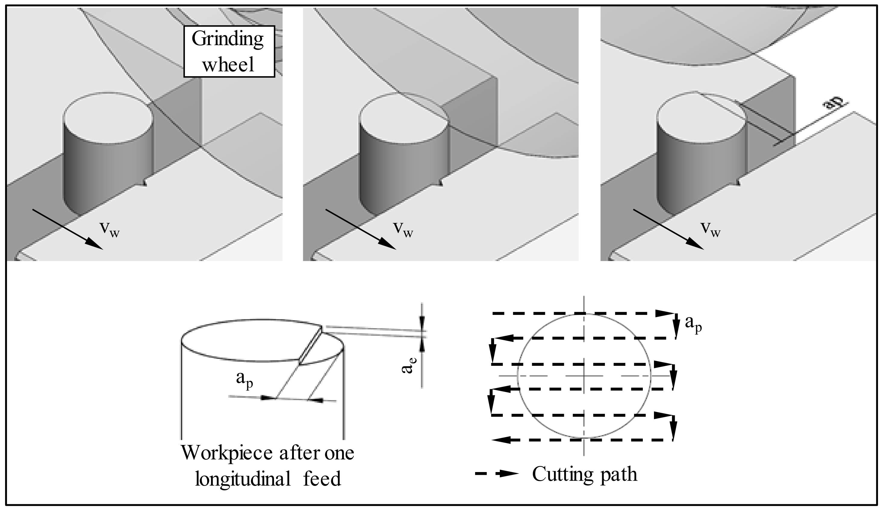
| Grinding Operation | Surface Grinding |
|---|---|
| Grinding wheel | Al2O3–38A46K6V–Ø 297 mm |
| Workpiece | 18 mm × 19 mm (diameter × height) SAE 52100 hardened steel–60 ± 2 HRC |
| Grinding wheel speed (vs) | 37 m/s |
| Workspeed (vw) | 3 m/min |
| Depth of cut per longitudinal pass (ap) | 0.9 mm |
| Radial depth of cut (ae) | 30 μm |
| Cutting environments | Cutting fluid at different temperatures: 5 °C, 10 °C, 15 °C and 28 ± 1 °C (room temperature–RT) |
| Cutting fluid | Semisynthetic vegetable-based oil Concentration–1:20 (5%), flow rate–9 L/min |
| Dressing conditions | aed = 15 μm vd = 140 mm/min Ud = 3 |
| Output parameters | Surface roughness (Ra parameter) Images of machined surfaces Microhardness and microstructure beneath machined surface |
Publisher’s Note: MDPI stays neutral with regard to jurisdictional claims in published maps and institutional affiliations. |
© 2021 by the authors. Licensee MDPI, Basel, Switzerland. This article is an open access article distributed under the terms and conditions of the Creative Commons Attribution (CC BY) license (https://creativecommons.org/licenses/by/4.0/).
Share and Cite
de Paiva, R.L.; de Souza Ruzzi, R.; da Silva, R.B. An Approach to Reduce Thermal Damages on Grinding of Bearing Steel by Controlling Cutting Fluid Temperature. Metals 2021, 11, 1660. https://doi.org/10.3390/met11101660
de Paiva RL, de Souza Ruzzi R, da Silva RB. An Approach to Reduce Thermal Damages on Grinding of Bearing Steel by Controlling Cutting Fluid Temperature. Metals. 2021; 11(10):1660. https://doi.org/10.3390/met11101660
Chicago/Turabian Stylede Paiva, Raphael Lima, Rodrigo de Souza Ruzzi, and Rosemar Batista da Silva. 2021. "An Approach to Reduce Thermal Damages on Grinding of Bearing Steel by Controlling Cutting Fluid Temperature" Metals 11, no. 10: 1660. https://doi.org/10.3390/met11101660
APA Stylede Paiva, R. L., de Souza Ruzzi, R., & da Silva, R. B. (2021). An Approach to Reduce Thermal Damages on Grinding of Bearing Steel by Controlling Cutting Fluid Temperature. Metals, 11(10), 1660. https://doi.org/10.3390/met11101660