Review

Influence of Honing Parameters on the Quality of the Machined Parts and Innovations in Honing Processes

1
Department of Mechanical Engineering, Barcelona School of Industrial Engineering (ETSEIB), Universitat Politècnica de Catalunya (UPC), 08028 Barcelona, Spain
2
Faculty of Mechanical Engineering and Shipbuilding, Gdansk University of Technology, 80-233 Gdansk, Poland
*
Author to whom correspondence should be addressed.
Metals 2023, 13(1), 140; https://doi.org/10.3390/met13010140
Submission received: 31 October 2022 / Revised: 21 December 2022 / Accepted: 29 December 2022 / Published: 10 January 2023
(This article belongs to the Special Issue Modelling and Simulation in Metal Cutting and Machining Process)

Abstract

:
The article presents a literature review dealing with the effect of the honing parameters on the quality of the machined parts, as well as with the recent innovations in honing processes. First, an overview about the honing and the plateau-honing processes is presented, considering the main parameters that can be varied during machining. Then, the influence of the honing parameters on surface finish, shape deviation and material removal rate is presented. Finally, some special and innovative applications of the honing process are described. For example, honing with variable kinematics allows obtaining oil grooves that are not rectilinear but curvilinear, in order to reduce the temperature of the part during machining and thus achieving better surface finish and lower shape deviation. Automation of the honing machines is useful to improve both the production and the verification process. Another innovation consists of using 3D printed tools in honing processes, which will help to obtain abrasive tools with complex shapes, for example by means of powder bed fusion processes.

1. Introduction

Honing is an abrasive machining process most often used for rough, semi-finishing, and finishing machining of cylindrical holes [1,2,3,4,5,6,7,8,9,10]. It is based on material removal by friction of an abrasive tool on a part’s surface [11], and it can be used for the final machining of the internal surfaces of round bars [12], valves [13], and gears [14] or for the manufacturing of hydraulic cylinders [13]. Honing may also be used for the final machining of gun barrels [15], turbochargers, and steering knuckles [16].
One of the key issues to be achieved after the honing processes is to obtain a good surface finish of the honed holes [17], specifically to create a characteristic texture on the surface of the machined hole consisting of a grid of oil scratches, i.e., straight lines intersecting at a specific angle, forming a cross-hatch pattern [18,19,20]. This helps to reduce emissions in the automotive industry [21,22]. Detailed information on the obtained surface properties after the honing process can be found in industry standards [23,24,25]. Dimkovski et al. [26] applied the segmentation algorithms to honed workpieces, to the surfaces taken from the top, middle, and bottom region of the investigated cylinder liner, and found that the axial scratches were most densely distributed in the top region as well as in the middle region, while in the bottom region there were only a few. They also stated that the plateau honing grooves were substantially preserved in the bottom and middle region of cylinder liners, largely removed in the top region, and were about the same size as the axial scratches in all the regions. On the other hand, Fiat Chrysler America reported that the cross-hatch angle on a honed surface should be about 36° [27], which means that some car manufacturers have established special technical data regarding the honing angle obtained on a machined surface after the honing process.
In addition, honing improves many useful functional parameters of the machined workpieces, such as roundness, cylindricity, straightness, etc. [28,29,30].
Many kinds of abrasives are used to conduct the grinding and honing processes of workpieces made from different materials. The abrasives may have different grain sizes, as well as different grain densities in the volume of the abrasive tool, and can have different binding materials for the grains. For instance, Sabri and El Mansori [31] compared vitrified bonded diamond abrasive stones (VBD) with the vitrified bonded Silicon Carbide (VBSC) ones and found that, for different speed values of the abrasive stone, the VBSC tools contributed to obtain lower values of the profile parameters of roughness, such as a reduced peak height (Rpk), core roughness (Rk), and reduced valley depth (Rvk). In addition, VBSC tools wore faster than VBD tools.
There are many kinds of honing processes, such as traditional honing and non-traditional honing [32,33,34]. Much of the literature deals with the honing process and with methods for checking and improving the performance of this abrasive machining process. Singh et al. [35] compared several finishing methods used for the final machining of cylindrical holes: abrasive flow machining (AFM), magnetic abrasive finishing (MAF), magnetic float polishing (MFP), magneto-rheological finishing (MRF), elastic emission machining (EEM), ultrasonic machining (USM), and ion beam machining (IBM) with the conventional honing process and stated that the honing process was the most suitable one for finishing internal cylindrical surfaces in most applications. Another example of an alternative process was described by Paswan et al. [36], who discussed the issue and advantages of magnetorheological honing. Honing is a final machining process, but workpieces can be further processed. Arantes et al. [37] have verified that the use of honing brushes to machine previously honed workpieces improved the roughness profile parameters obtained on machined surfaces. Specifically, the Rk and Rpk parameters significantly decreased after the use of flexible brushes, and a certain decrease was also observed for the Rvk parameter [5].
Honing machines can be conventional or numerically controlled (CNC honing machine tools) [38,39,40,41,42,43], either with vertical or horizontal configuration [44], and can have one or more spindles in order to increase productivity, for example six machining spindles. The honing process can also be conducted on drilling machines, on lathes, or on milling machines [45,46,47]. Modern machine tools controlled by servo and with specific software are also used for honing, which enables the production of a textured surface with the use of highly dynamic infeed of a piezo actuator [48]. In addition to modifying the design of honing tools, the literature also includes information about auxiliary elements of the machines, for example, adding the possibility of automatic measurement of the hole’s diameter during honing, which would allow the optimization of the course of the honing process. On the other hand, Deshpande et al. [9] proposed replacing the machining carried out in several machine tools with machining in only one multi-spindle honing machine with a roughing tool prepared for rough machining, a finishing tool and a flexible brush to be used after finishing the honing. On the other hand, Komet Group proposed a honing tool that can be implemented in CNC milling machines [49], while Honingtec manufactured a tool that can be adapted to both conventional or CNC machines [13].
According to Schmitt et al. [50], the honing process is characterized by three overlapping movements of the honing tool: rotation around the tool axis, oscillation along the tool axis, and the feed movement of the honing stone in the radial direction (this is explained in further detail in Section 2). During honing, the position of the honing head and the value of the honing force can be controlled to improve the conduction of the honing process. An axial movement is transmitted into a radial movement of the honing stone. This movement can be either feed-controlled or force-controlled. With feed-controlled honing, the honing stone is fed outwards in certain steps, at certain time intervals. With force-controlled honing, the height of the feeding steps is dependent on the difference between the wanted and measured process forces and this leads to different process forces during the honing process [50].
Honing is used to produce components with a finely finished machined surface, with a good geometric quality [51]. Plateau honing is used, above all, to reduce the costly running-in period, as was specified by Mezghani et al. [52].
Honed holes can have diameters between 1 mm and about 2 m and can have lengths from fractions of a mm to a few meters. It is possible to obtain holes with diameters from 0.015–0.03 mm to 1.5 mm using a method called Microcut Bore Sizing, which was described by Pawlus et al. [53].
The main advantages and disadvantages of the honing processes are presented in Table 1.
Honing is performed on tubes and cylinders used in lifting, engine components, and robotic industries. Saint-Gobain Abrasivi [56] reported that honing was used in hydraulic arms for cranes and hoists, plastic extrusion cylinders, hydraulic jacks and lifting platforms with hydraulic or oil pistons, and on spherical valves, controlling the flow of gas, oil, or water with a simple opening and closing system in pipelines.
Schmid et al. [57] showed that another field of activity for production development was the fine machining of fractionality-favorable materials, e.g., coatings (for example Plasma coating). The main advantage of a porous sprayed layer is that the surface topography remains practically constant over the entire service life of the engine, regardless of wear. In car-race applications, plasma coatings are influential in the sense that engines with plasma coatings have practically no run-in phase.
Karpuschewski et al. [58] remind that honing is used to reduce fuel consumption and the amount of pollutants (CO2, NOx) generated during the use of an internal combustion engine. Around 30% of world energy consumption is used to overcome the friction in tribo-pairs of mechanical elements. Grzesik [59] noted that a very important engineering problem was an issue of the reduction of friction between cooperating elements. Friction reduction of a piston group by 5% is equivalent to approximately 1% less engine friction [60,61,62]. Depending on the finishing method, a different coefficient of friction for the friction pair is obtained and it is also important that the finishing machining is carried out with low process forces. Honing is used to reduce oil consumption during the operation of an engine, as reported by Johansson et al. [63]. Honing provides a lower coefficient of friction than the surface ground in the abrasive pair. Kim et al. [64] compared the coefficients of friction for samples honed with an angle of 40 degrees and for samples honed with an oil groove intersection angle of 140 degrees. Depending on the lubrication conditions, samples honed with an intersection angle of oil channels of 40 degrees provided a lower friction coefficient compared with samples having an intersection angle of 140 degrees. Kim et al. [65] reported that samples with a honing angle of 140 degrees provided a lower coefficient of friction.
Korczewski et al. [66] describe the procedure for verifying the condition and repairing the worn surface of the cylinder liners of a marine internal combustion engine using honing. Hu et al. [67], Iliuc et al. [68], and Jocsak et al. [69] report that it is particularly advantageous to hone the surface of the cylinder bore of an internal combustion engine in order to reduce the friction coefficient in the friction pair cylinder-rings, especially in the top dead center (TDC).
Ogorodov [70] described the problem of the honing fixture that enabled the fixturing of thin-walled cylinders, and stated that by using appropriate combinations of the spring configuration it was possible to obtain the required axial geometry of the honed holes, and that the specified deformation of the thin-walled cylinder might also be used to intensify the correction of the initial hole distortion in the honing process. Uhlmann et al. [71] described the possible scenarios for clamping the honing head and the machined workpiece and summed up the advantages of the various machining methods. Rigid clamping of the honing head and the honed workpiece enabled the cylindrical straightness and the proper positioning of the honed hole. In case the honing head is rigidly guided in the honed hole, but the workpiece is not rigidly mounted, or when the workpiece is rigidly mounted but the honing head is not guided, this will allow cylindricity and straightness to be corrected, but it will not improve the position of the hole.
The course of the honing process is influenced by the value of the parameters used in the manufacturing process. Allard [72] discusses individual parameters that significantly affect the obtained machining result. Examples of these parameters are: the value of the pressure of the whetstone on the surface to be machined, the number of honing cycles, the honing angle, and the machining speed. Schmitt et al. [73] reported that a honing process conducted with a constant honing force could improve the quality of the honed holes.
Although conventional honing processes are well known, new requirements in productivity, surface finish, or friction reduction between piston and cylinder liner open new fields of research. In the present work, first the influence of honing parameters on the roughness, shape deviation, and material removal rate is discussed. Then, three main types of innovations are presented: use of variable kinematics, automation of the honing machines, and use of additive manufacturing technologies to improve the performance of the honing tools.
The following sections are considered. Section 2 describes the main parameters of the honing process, Section 3 deals with effect of the honing parameters on surface finish, Section 4 deals with effect of the honing parameters on shape deviations of honed holes, considering the influence of the workpiece temperature, Section 5 deals with the effect of the honing parameters on material removal rate, Section 6 is about the recent innovations in the honing process, and Section 7 and Section 8 are the discussion and the conclusion sections of the paper, respectively.

2. Parameters of the Honing Process

Figure 1 presents the system of speeds occurring in honing processes [74]. The honing head is usually provided with rotation movement and linear reciprocating movement. The radial displacement of the abrasive stones can be achieved by means of different mechanisms, for example using a mandrel with conical elements (Figure 1, position 3).
The basic formulas defining the honing kinematics are (1)–(4):
Cutting speed Vc [m/min]
V c = V a x 2 + V a z 2
where: V a x —axial linear velocity of the honing head in reciprocating motion [ m min ]
V a x = 2 L n a x [ m min ]
  • L—stroke length of the honing head in reciprocating motion [m]
  • n a x —stroke frequency of the honing head in reciprocating motion [ 1 min ]
  • V a z —peripheral speed of the honing head [ m min ]
V a z = π d n 1000 [ m min ]
  • n—rotational speed of the honing head [ obr min ]
  • d—diameter of the honing hole [mm]
  • α —honing angle [°]
t g = V a x V a z
The parameters influencing the honing process were characterized, among others, by Wooldrige [75]: process:
pressure of the abrasive whetstone to the honed surface;
material of the abrasive tool;
cutting speed;
honing angle;
width of the abrasive tool;
type of cutting fluid;
size of the abrasive grain.
Pastor [11] listed the principal variables of honing process:
specific pressure value of abrasive whetstone to the honed surface;
cutting speed, formed by two components: rotation and axial speed
coolant fluid;
temperature of the coolant;
composition of material to be honed and their production variations;
kind of abrasive grain;
grit size;
kind of abrasive bind;
surface status of the workpiece before honing (superficial hardness, roughness, protective impregnations, electroplate depositions, etc.);
temperature of the workpiece during honing process;
expansion speed of abrasive whetstones;
kind of material to be removed.
With regard to the properties of honed workpiece, exemplary parameters influencing on conducting of honing process are detailed by Uhlmann et al. [71]:
material of the workpiece;
dimensions of honed hole;
deviations of the initial shape of honed hole and assumed after machining;
the quality of the machined surface;
the number of abrasive stones for the tool;
tool dimensions;
grain material;
binder material;
grain size and its concentration;
condition of the abrasive tool surface.
One of the key parameters of the honing treatment is to provide the characteristic surface texture along with the required roughness profile parameter values.

3. Effect of Honing Parameters on Surface Roughness

As for the effect of the number of strokes of the honing head on material removal rate and roughness, Mezghani et al. [52] observed that a greater material removal rate value is observed for a higher number of strokes (one stroke is one up-and-down movement of a honing head). Additionally, as the honing process continues, with each subsequent stroke of the honing head, roughness of the honed surface decreases.
The obtained honing efficiency results from the machining parameters, from the value of axial, tangential, and normal speed as well as the size of the abrasive grain [76]. Vrac et al. [77] also reported that, by using a finer grain of abrasive, it was possible to obtain the same value of an Ra parameter as it was for coarser-grained tools, with different cutting conditions.
Another important issue is ultrasonic honing with oilstone’s axial ultrasonic vibration. Wang verified that ultrasonic vibration honing had an influence on the significant reduction in the surface roughness profile parameter Ra, and it reduced its value by about 50% [78].
Cabanettes et al. [79] found that only a few roughness parameters (of a machined surface) out of 65 were significantly correlated to honing tool wear. For example, the functional parameter Spk (areal reduced peak height) and Ssc (arithmetic mean summit curvature) were strongly correlated. Both parameters describe the upper part of a surface. This observation is in line with the fact that honing is a super-finishing process acting on the asperities of cylinder liners.
Buj-Corral et al. [80] reported that the grain size had a high influence on all studied roughness parameters, and that the larger the grain size was, the rougher the surface. When the same grain size was used, higher pressure caused higher roughness, because abrasive grains dug into the workpiece surface and made deeper marks on it. Tangential speed had a slight effect on roughness. The same authors [81] found that, from a density of 30 onward, the higher the density, the lower the roughness, and that material removal rate (MRR) increased with density of up to 45, which showed relatively low roughness and tool wear. For a density of 60, clogging was so significant that the honing stone lost its ability to remove material, with the lowest MRR value. They reported that tool wear was inversely proportional to abrasive density. When a density of 60 was used, since clogging occurred, the abrasive grains did not work properly and, for this reason, the abrasive did not wear significantly. To create the oil channels, as was described by Wang [82], it is very important to choose a proper grain size in each honing step. The shape and the roughness of cylinder holes are closely related to the honing stones used, and the obtained quality of a honed surface has a profound effect on tribological performance, because the cross-hatch pattern on the workpiece surface can be used to retain oil or grease and ensure proper lubrication and to minimize wear of cooperating components, for example, in the cylinder liners of combustion engines. Depending on the abrasive material used and the value of the pressure of the whetstone to the honed surface, different values of the surface roughness profile parameters are obtained [83]. Cutting pressure defines the penetration depth of the cutting grains into the honed material of the workpiece. Additionally, it should be noted that the quality of the honed surface is also influenced by the material of the abrasive tool used in the honing process. For example, in order to increase machining efficiency, diamond grain can be used, which increases machining efficiency but, due to the strength of diamond grains, causes an increased amount of machined material remaining in the oil channels [84]. Szabo [85] confirmed that the super hard grain material and largest grain tools provided significant productivity and accuracy compared to traditional grain material tools and that the abrasive tools had a high stability and life. As previously stated, the main parameter influencing the roughness parameters, e.g., Ra, on the honed surface is the grain size and the value of the pressure of the whetstone against the honed surface [86,87,88]. There is a certain range of machining parameters that allow obtaining a smoother honed surface. Tripathi noted that pressure of abrasive stones on the machined workpiece surface, honing speed, and the honing time influenced the surface roughness parameters [89]. As the working pressure of the abrasive whetstone on the machined surface increased to a certain value, the obtained value of the Ra parameter decreased, and then, with the next increase in the working pressure, it only increased constantly. Similarly, as the machining speed increased to a certain value, the obtained value of the Ra parameter decreased, and then remained at a similar level. With the increase in honing time, the value of the honed surface roughness decreased. To sum up, the obtained value of the parameters of the roughness profile for the machined surface depends, among others, on the grain size: the smaller the grain, the smaller the value of the Ra parameter, as described by Entezami et al. [90]. According to Kadyrov et al. [91], the values of the roughness profile parameters for the honed surface are influenced by the pressure of the abrasive stone on the machined surface, the amount of material removed, and the honing time. The number of honing steps also determines the parameters of the roughness profile of the machined surface. Kurzyna et al. [92] compared two-stage honing, three-stage honing, and honing with the additional use of a honing brush in the third stage of treatment. The obtained results show that three-stage honing with a honing angle of 30–60° ensured the lowest value of the Ra and Rz parameters. They also reported that there might be more than 3 stages, e.g., the 4th stage might be stream honing of liquid with a pressure of 12 MPa, which removes particles very weakly bound to the base material of the honed surface. In order to improve the parameters of the roughness profile for the honed surface, Ozdemir et al. [87] suggested that in the final stage of machining, honing brushes (mounted in the same way as abrasive stones) should be used. Rosén and Garnier [93] stated that the possibilities for surface geometry characterization using 3D metrology ranged from robust statistical parameters like the arithmetic surface mean height (Sa) and root mean square height (Sq) to more specialized summit shape and texture direction descriptors. Günay and Korkmaz [94] noted that, depending on the size of the abrasive grain used, a reduction in the roughness profile parameter value could be achieved along with the reduction in the abrasive grain size. The verification of the conducted process and of the obtained texture in the honing process is very important [95,96].
As described by Sabri et al. [97], some engine parts, such as cylinder liners, have a value for their honed surfaces like an Rpk parameter around 0.3–0.5 μm, an Rk around 1 μm, and an Rvk around 1–1.5 μm. They reported that some manufactures in the automotive industry, such as Renault or PSA Citroen, introduced other parameters describing the functionality parameters, such as Cr (Running-in criterion), Cf (operating criterion), and Cl (lubricating criterion). The increase in the pressure of the whetstone during rough honing increases the depth of the oil channels, which means an increase in the value of the Rvk parameter [98]. Lawrence [7] noted that the main influence on Rk, Rvk, and Rz parameters was the rotational speed of a honing head; on the Rpk parameter it was the oscillatory speed; on the Mr1 parameter it was the honing time, and on the Mr2 parameter, the pressure of a honing whetstone. As Michalski and Wos [99] stated, the smaller depth of the oil channels, i.e., the smaller value of the roughness profile parameter Rvk, the lower the wear of cylinder elements and piston rings. Depending on the density of the oil channel arrangement and on the depth of the oil channels, different oil pressure profiles are obtained between the mating surfaces in the friction pair in the cylinder of an internal combustion engine.
Bouassida [100] has discussed the effect of the cross-hatch angle obtained in different places on the honed hole’s surface, as well as of the depth and width of the lubricating grooves. The deepest grooves reached a depth of 2.7 µm and 2.2 µm with an average value of 0.93 µm and 0.66 µm. The average value of the honing angle was 22°, the width of the grooves was about 30 µm, and grooves with a greater width, about 80 µm, were also found.
Schmitt et al. [101] described the implementation of an acoustic signal analysis to the examination of the honing process. In the same field, Buj-Corral et al. [81] defined a new S-parameter that determines the relationship between energy in low and high frequencies contained within the emitted sound. The selected density of 30 corresponds to S values between 0.1 and 1. Correct cutting operations in honing processes are dependent on the density of the abrasive tool used in the honing process.
Raza [102] described the hydrodynamic effect of a single idealized dimple, created on a honed surface, and the creation of additional hydrodynamic force due to a different hydrodynamic pressure distribution over diverging and converging parts of the dimple. He showed that the pressure decreased as the oil flow approached the bottom center of the dimple but on the symmetrical side, the pressure increased. He also stated that the tribological behavior of textured surfaces depended on the properties of the oil used in the friction pair. Raza reported that:
-
For higher viscosity oil (ISO VG 320), textured specimens did not show any beneficial effect in reducing friction;
-
For medium viscosity oil (ISO VG 150), all the textured specimens showed a lower coefficient of friction than smooth specimens for higher sliding speeds (1.0 and 1.27 m/s);
-
For lower viscosity oil (ISO VG 46) the beneficial effect of micro-grooves becomes larger with a decrease in groove density as well as for higher sliding speeds (0.5, 1.0 and 1.27 m/s).
Raza also observed that the beneficial effect of surface texturing occurred at the mixed lubrication regime.
Reizer et al. [103] described the parameter changes observed during wear and stated that the statistical height parameters Sq and Sv decreased. However, the core depth Sk increased. Lawrence [7] reported that different sizes of abrasive grains could be used in the honing process, that is, from 7 μm to 250 μm, and the larger the grain used in the honing process, the higher values of the roughness profile parameters obtained on the machined surface, e.g., Rpk, Rk, and Rvk. Sabri et al. [104] reported that the roughness amplitude was proportional to the expansion speed of an abrasive whetstone. For rough honing, El Mansori et al. [105] used a honing head equipped with 8 diamond stones with a grain size of 120 μm, for finishing honing used 6 silicon carbide stones with a grain size of 80 μm, and for plateau honing used a honing head equipped with 4 silicon carbide stones with a grain size of 40 μm. The number of strokes has a great impact on the honing process. Mezghani et al. [52] described the effect of the stone spreading speed on the friction coefficient and on the value of the parameter of the honed roughness profile Rk. It can be noted that the lowest value for the spread of the abrasive stone affects the receipt of the lowest value for the Rk parameter. With the increase in the speed of spreading the whetstone, the obtained value of the Rk parameter also increases. Mezghani et al. [52] described the effect of the stone spreading speed on the value of the parameters Rpk and Rvk. It could be noted that the lowest value of the speed lead to the lowest value for the Rpk and Rvk parameters. With the increase in the speed of setting the stone, the obtained value of the Rpk and Rvk parameters also increased.
A special texture can be obtained in cylinders when the plateau honing processes is applied. Figure 2 shows the surface roughness profile of the plateau surface during the subsequent processing steps. Figure 2A schematically shows the roughness profile after rough honing, Figure 2B shows the finishing stage, characterized by the removal of the peaks of the roughness profile with fine abrasive grains, and Figure 2C shows the surface of the plateau after the finishing step of a honing process, characterized by oil reservoirs for distributing the oil with a reduced height of the peaks of the roughness profile of the machined surface.
The Abbot Curve is used to present the characteristics of the honed surface on which, among others, the roughness profile parameters from the Rk group are defined, such as Rpk, Rk, and Rvk (Figure 3). Masip et al. [106] described how to obtain a plateau surface after the honing process. In the first step of the honing process rough honing tool should be used with a large size of abrasive grain, and in, for example, the second step, a finishing tool with a small size of abrasive grain.
Masip et al. [106] also described the change in the Abbot curve diagram (Figure 3) depending on the number of strokes of the honing head. The greater the amount of honing head oscillation, the greater the flattening of the Abbot curve.
Reizer and Pawlus [107] found that plateau honing time was the most important parameter affecting Sq, S10z (ten-point height), Sdq (root meam square gradient), Spq, Svq, and Smq surface topography parameters. They also stated that the effect of coarse honing pressure on plateau honed surface topography parameters was negligible. They assumed that surface topography parameters were strongly correlated when the absolute value of the linear correlation coefficient ρ was greater than 0.7. Amplitude parameters were strongly interrelated, especially Sa and Sq. These statistical parameters are highly correlated with Sp, Ssk (skewness of the surface), Sp/Sz, SHtp (surface section height difference corresponding to 20–80% of material ratio), Sdq, Sdr (developed interfacial area ratio), Spc (arithmetic mean peak curvature), Spd (density of peaks), Svi (valley fluid retention index), Sk, Svk (areal reduced valley depth), and Smr1 (material ratio of summits) parameters. However, they were not statistically connected with parameters describing maximum surface height. Skewness was inversely proportional to kurtosis. Hybrid parameters Sdq, Spc, and Sdr were also highly correlated. Among the spatial parameters, Str and Sal were independent of other parameters but mutually interrelated. The Std parameter was independent. The parameters Spq, Svq, and Smq were mutually independent and also not correlated with the other parameters. Parameters from the Sk family (Spk, Sk, Svk, Smr1, and Smr2 (material ratio of valleys)) were mutually independent.
Obara et al. [84] observed the histograms of the plateau-honed topographies and noticed that the three steps of the honing process resulted in a stratified surface with two different distributions: one associated with peaks and core and another with the valleys. Due to the partial removal of peaks, plateau-honed surfaces provide good tribological behavior and the skewness is negative, resulting in a surface with an asymmetric probability density function. Mezghani et al. [52] concluded that smooth surfaces led to better friction performances despite the increases in the ratio between plateau and valley height (non-plateaued surface).
Plateau honing is characterized by the following roughness profile parameters [46].
-
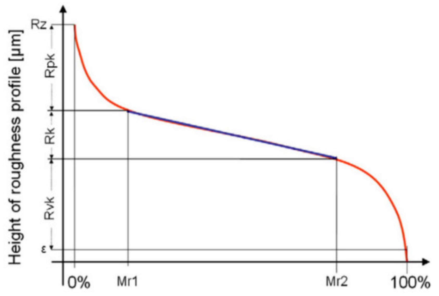
Rpk 0.1–0.3 μm (average value 0.2 μm);
-
Rk 0.8–1.2 μm (average value 1 μm);
-
Rvk 1.2–2 μm (average value 1.6 μm);
-
Mr1 2–10% (average value 6%);
-
Mr2 70–85% (average value 77.5%);
-
Rz (DIN) 3–4 μm (average value 3.5 μm);
-
Honing angle 40–55° (average value 48°).
Graboń and Pawlus [108] found that the wear of two-process surfaces was lower than that of one-process surfaces characterized by the same Sq parameter. Linear wear of specimens was proportional to the initial values of the parameters Sk and Sq, and wear intensity decreased constantly for sliding distances larger than 1.6 km. They also determined optimal values for the Sq parameter (0.4–0.7 μm), for which the coefficient of friction reached a minimum value. The values of the coefficient of friction usually decreased during the wear process. Graboń and Pawlus also stated that, during the “zero-wear” process, a two-process structure was created. The characteristic feature of the wear process was a decrease in skewness of the surface Ssk, as well as an increase in kurtosis of the surface Sku and in the spatial parameter Sal. Amplitude parameters characterizing the peak surface of machined part Sp and Spk decreased. They also reported that the greatest changes took place in parameters Ssc and Sbi (surface bearing index). The largest parameter (especially describing the peak surface part) changes were noticed after 0.5–1 h of operation.
On the other hand, texturing of the workpiece surface (area density between 20–26%) using a burnishing technique resulted in a significant improvement in wear resistance in comparison to a system with untextured samples. The area ratio of 26% minimized the linear wear of the tested assembly by 27% in comparison to a system with a turned workpiece. Before burnishing, liners were plateau-honed [109,110]. However, the oil pocket area ratio should not be very big, because it could cause an increase in unitary pressures and then an increase in wear intensity. The smallest wear was obtained for the biggest dimple depth. The microscopic observations revealed that the oil pockets were filled in by wear debris. Napadłek [111,112] discusses the process of honing a cylinder liner made of heat-treated 41CrAlMo7 alloy steel subjected to a gas nitriding process, which is used in internal combustion engines. The first stage of machining is boring, i.e., rough machining the hole (the drilling process is not considered), then the hole was roughly honed. The next operation was gas nitriding followed by laser texturing, consisting of creating oil reservoirs in the upper part of the cylinder. One of the methods for reducing the friction coefficient of the rings in the cylinder is the use of additional coatings, e.g., SUMEBore [113], which improve the tribological properties of the piston rings-cylinder surface in the friction pair. Vladescu et al. [114] showed that dense oil pockets ensured the lowest friction value in the mating friction pair under mixed and boundary regimes, whereas sparser patterns showed lowest friction at the transition between mixed and full film lubrication regimes and that the deep pockets were beneficial in the boundary lubrication and at the transition between boundary and mixed lubrication regimes. They confirmed that rectangular surface pockets were effective at reducing friction when they were oriented with their long axis transverse to the sliding direction, for example, in cylinder liners of combustion engines, and that shallower pockets were beneficial at the transition between boundary between the mixed regime and full oil film regime. Wos et al. [115] described the issue of texturing of honed surface using additional oil pockets and stated that the best tribological performance was obtained for both surfaces textured with the smallest pit-area ratio of created oil pockets of 2.25%.
Kurzyna et al. [92] compared traditional honing performed with the honing angle of 30–60° of grooves with spiral honing, characterized by a honing angle of 135°, and stated that lower oil consumption could be observed for spiral honing. Muratov and Gashev [116] presented examples of curvilinear paths that could be produced on the honed surface during honing carried out with variable kinematic parameters. Yousfi et al. [117,118,119,120,121,122,123,124] dealt in detail with the issue of texturing honed surfaces, focusing on the development of new shapes for abrasive grain trajectories. They discussed the possibility of generating various shapes for curvilinear oil channels, as well as rectilinear paths intersecting at different angles. Another important issue regarding micro-grooves created on a honed surface is the shape, density of distribution, and depth, but also, for micro-grooves in rectangularly shaped oil containers, the direction of distribution in relation to the direction of cooperation of mutually frictional elements. Yuan et al. [125] concluded that the grooves with a depth around 7 µm and perpendicular to the sliding direction had a better effect on friction reduction than those of a parallel orientation. Compared to the untextured surface, these grooves could reduce friction in a tribo-pair up to 38.2%. Galloway Engines [20] stated that the ideal finish of an engine was made up of a pattern of oil grooves along the surface of the hole. Under magnification, these scratches make up a series of peaks and valleys [126]. The piston rings run up and down along the peaks and the valleys act as oil reservoirs for the lubrication of the cylinder. Galda et al. [127] reported that at loads equal to 0.8 MPa and sliding velocities in the range of 0.02–0.2 m/s, the cavities in the sliding surface improved the tribological characteristics with poor lubrication. With a low degree of coverage of the surface with the recesses equal to about 3% and the quotient h/d (h—depth, d—diameter of oil pockets) of the recesses close to 0.1, the coefficient of friction was lower by more than 60% in comparison with the µ (coefficient of friction) of the ground surfaces. At higher pressures of about 3.2 MPa, the presence of cavities in the surface in most of the tested cases did not have such a beneficial effect in terms of reducing the coefficient of friction. One of the tested variants (Sp = 3%, h/d = 0.11 and the oil capacity of oil pocket Vi = 130,000 µm3) was characterized by a coefficient of friction lower by 40% to more than 50% compared to the sliding joint with ground surfaces. They also found that the presence of cavities with a specific geometry and a defined degree of surface coverage improved the operation of sliding in conditions of poor lubrication at low sliding speeds. Due to the accumulation of a lubricant in the recesses, which under certain conditions can take part in the load transmission, it is possible to reduce the micro-areas of contact of the mating surfaces in the sliding joints.
Gropper et al. [128] reported that surface texturing remained a feasible method for contact performance enhancement in terms of load carrying capacity, minimum film thickness, friction, and wear. They also stated that robust numerical models allowed the evaluation of texture designs prior to being manufactured and could avoid time consuming experimental trial and error approaches. Guo et al. [129] confirmed that the lubrication performance of the cylinder liner and piston ring pair varied with different surface texture structures. The regular concaves, created on a machined surface, improved the operation condition of the cylinder liner and piston ring pair. They also stated that on the same surface texture, the regular concave with a depth-diameter ratio of 0.1 was more favorable for improving the lubrication of the cylinder liner and piston ring pairs than that with the 0.3 ratio.
Hoffmeister et al. [130] found that the parameters of the honing process had a significant influence on the honed surface topology. Where a high infeed pressure at the honing of conventional materials like gray cast iron could lead to formation of so called “blechmantel” (cold worked material), it resulted in the formation of a lid burr extending into the pore cavities at the honing of thermally sprayed layers. This new kind of burr could be detected on the SEM images of the machined surfaces and was expected to negatively affect the tribological properties of the cylinder running surfaces. Hoffmeister reported that, for the SUNA6-3 layers, limits regarding the maximum infeed pressure at the finish honing have been shown by the clogging of the honing stone. The influence of the other process parameters like infeed step width and cutting speed on the material removal rate and surface roughness were comparable to honing conventional materials. Due to the high initial roughness of the thermally sprayed layer, Hoffmeister reported, that the first honing step subjects the honing stone to high abrasive wear.
Howell-Smith et al. [131] concluded that the regime of lubrication changed throughout the working piston cycle. As a result, during the engine cycle, boundary interactions as well as viscous shear of the lubricant film contributed to the parasitic frictional losses. The contribution of boundary friction was dominant in piston reversals at the TDC (top dead center) and the BDC (bottom dead center), and particularly in transition from the compression to the power stroke, as predicted and measured by many research workers. They also stated that the adherence of lubricant to the bounding surfaces is a function of the lubricant molecular species, as well as the surface energy and topography. At the TDC and the BDC, the presence of hard coatings resists wear. Howell-Smith confirmed that hard coatings were generally oleophobic to a certain degree. Thus, surface modification was beneficial at the TDC to create reservoirs of lubricant, which also encouraged lubricant entrainment into the contact at low sliding speeds (the microwedge effect).
Whitehouse [95] and Malburg et al. [132] stated that the honing process could reduce the run-in period and the oil consumption by modifying the local geometry. Mezghani et al. [133] discussed the issue of the influence of the oil channel width on the obtained coefficient of friction and confirmed that the greater width of the oil channel caused a reduction in the value of the friction coefficient and the greatest decrease in the value, because by 300%, it could be observed with the increase in the width of the channel from 6 μm to 18 μm. With a further increase in the width of the oil channel, the decrease in the friction coefficient was still observable, but not so significant. They also discussed the problem of the influence of the density of oil channel distribution on the textured surface and noted that with the increase in the number of channels from 16 to 20 channels/mm2, the value of the coefficient of friction decreased. For 20 channels/mm2, the lowest value of the friction coefficient was obtained. On the other hand, with further densification of the number of oil channels, an increase in the coefficient of friction was observed, although it should be noted that with a greater number of oil channels (e.g., for 44 channels/mm2) the obtained coefficient value was lower than, e.g., for 16 channels/mm2.
Dimkovski et al. [134] reported that the calculated parameters from the roughness surfaces and their visual inspections showed that the processed material lying in the oil channels from the honed holes top region was largely removed (the surface was almost polished) while the blechmantel from the other regions was much less well removed, leaving open a possibility of causing wear. They found that this polished area was quite small (2–3%) compared to the whole running surface, which suggests that more blechmantel could be removed before serious damage might or might not occur. In the engine tests, the diamond honed liners showed good performance and the registered quantities of blechmantel and axial scratches were within tolerance limits for the present state [134].
Dimkovski et al. [135] concluded that a lower base honing pressure and relatively longer plateau honing time were needed to slide-hone to receive a well-honed cylinder liner surface finish. They also stated that the roughness parameters that quantify surface features like valley component, deep honing grooves interrupt and blechmantel, plateau roughness (Sk and Sdq), summit denMsity (Sds), size/volume, and curvature (Ssc) were important for characterizing a good functioning liner surface. The study suggests that liner surfaces that have smaller valleys and smoother plateaus with more and flatter summits would reduce friction and oil consumption.
Finally, to end this section, as an example of finishing honing processes, Figure 4 shows profiles obtained with grain size of 30 and 15 respectively, using cBN stones on St-52 steel.
An irregular profile was reported in both cases, corresponding to abrasive machining processes. When a high grain size of 30 was used, higher peaks of 3 µm and lower peaks of −3 µm were obtained. On the contrary, a low grain size of 15 led to high peaks of 0.5 µm, with some valleys of −0.9 µm, which could be attributed to the previous surface finish of the cylinders obtained by means of lamination processes.

4. Effect of Honing Parameters on Shape Deviations in the Honed Holes

The honing process can make a hole with desired properties, round with a straight shape with a fine degree of precision, with a high process capability and accuracy measured in tenths of a micron [16].
Xi et al. [136] showed that the stroke length was the main factor, followed by honing pressure, that affected the cylindricity of inner-hole honing. Zhang et al. [137] stated that the cylindricity of an engine cylinder hole was primarily determined by five groups of factors, such as machine tool and fixture stiffness, honing head structure, the arrangement of honing stones, the property of material of engine cylinder block, the honing process parameters and the previously generated initial cylindricity of the honed hole in the previously conducted machining.
Sabri and El Mansori [31] reported that some of manufactured parts, for example cylinder liners, had to be machined with a roundness deviation of less than 5 µm, cylindricity of 10 µm, and finish requirements of less than 2 µm of the Rk surface roughness parameter. They described the effect of the VBD and VBSC stone spreading speed (“VBD” means a vitrified bonded diamond abrasive stones, and “VBSC” the vitrified bonded silicon carbide) on the cylindricity of the honed hole. For the spreading speed of 1.5 µm/s they obtained the lower cylindricity deviation for the VBD stone. For higher stone spreading speeds of 2.0 µm/s and 8 µm/s, they obtained the lowest value of cylindricity deviation for the VBSC stone.
One of the main goals of the honing process is to reduce the shape deviation of honed holes. Holes intended for honing may have different shape deviations (cylindricity, conicity, deviation of the shape of the axis of the hole) and depending on the type of deviation, a different value of the whetstone run-out should be used. This issue has been discussed in detail in the literature, for example by Bujukli and Kolesnik [138]. The shape of the cooperating components affects the thickness of the oil layer in the piston-cylinder friction pair. Johansson et al. [139] reported that a reduction in the thickness of the oil between the cooperating surfaces has a good effect on the friction in the tribo-pair of piston-cylinder for reducing the wear of mating elements.
Voronov [140] and Voronov et al. [141] concluded that the main parameters impacting on the dynamics of the manufacturing system and formation of the machined surface were the radial stiffness of the compression bars, the pressure of the initial compression during the honing process, and the speed of rotation of the honing head.
Akkurt [142] presented information describing the influence of the type of hole treatment of cylindrical holes on the obtained surface parameters. He presented information about the size of the roughness profile parameters that could be obtained during grinding, reaming, drilling, turning, honing, and burnishing. He pointed out what amount of hole shape deviation could be obtained for particular types of machining, and it turned out that the honing process significantly improved the cylindricity of the machined hole compared to other manufacturing methods. Burnishing was also one of the lead manufacturing methods enabling to obtain similar parameters for a machined surface.
Kapoor [143] described the effect of changes in reciprocating speed and rotational speed on an improvement in out of roundness (∆OOR) and observed that for a constant overrun equal to 16 mm, there was an increase in the percentage of improvement in out of roundness with an increase in the value of the reciprocating speed. The maximum ∆OOR was observed at a higher reciprocating speed and at a relatively lower rotational speed. At higher a rotational speed of the honing head, ∆OOR declined for all values of reciprocating speed. This might be due to the fact that, at higher values of rotational speeds, there is the possibility of deformation of the honed workpiece due to overheating, so there was less improvement in ∆OOR. The helix angle for maximum improvement in out of roundness was observed to be 20°.
El Mansori et al. [105] confirmed the influence of the axial acceleration of the honing head movement on the cylindrical deviation. For an acceleration with a value of ≤1 g and for an acceleration with a value of ≥2 g, greater deviations in the cylindricity of the honed hole were obtained than for the machining carried out with the acceleration value of 1.5 g (g—gravitational acceleration value). The greater the value of the honing head travel velocity in the axial direction, the greater the angle of intersection of oil grooves. Mezghani et al. [144] proved that helical honing reduces the friction coefficient in the piston-cylinder assembly compared with the plateau honing process.
The value of the pressure of the abrasive whetstone against the honed surface plays a significant role on the deviation of the cylindrical shape of the honed hole. Muratov and Muratov [145] proposed a machine tool for honing of cylindrical holes with a mechanism that allows changing the value of the pressure of the abrasive stone against the machined surface, which allows for obtaining holes with a minimum deviation in the size and shape tolerance. A honing machine equipped with system of changing the value of the pressure of the whetstone on the honed surface allows obtaining the accuracy of the dimension within the tolerance from 0.003 mm to 0.005 mm with the cylindrical deviation value in the range of 0.01 mm to 0.012 mm [145].
A particularly important issue for the honing treatment performed is the temperature increase of the honed workpieces. Increased temperature affects the formation of stresses and thermal deformations, and also makes it difficult to measure the obtained diameter of the workpiece. The increase in temperature during processing may reach several tens of degrees Celsius [47,146,147,148,149], which affects the thermal expansion of machined workpieces. The greater material removal rate, the higher the temperature of the honed workpiece and its hole deformation [74]. In order to reduce the workpiece temperature, it is very important to optimize the honing process parameters [150]. Some of the ways to lower the workpiece temperature are to intensify cooling, to add an oil cooler, and to implement variable honing kinematics [1,41,47,74,151].
Spencer et al. confirmed the influence of the honing angle on the minimum oil film thickness and reported that the variation in film thickness for different honing angle values was minimal, but with an increase in honing angle the thickness of oil film decreased [152]. Very important to the honing process are the influence of kinematics and the shape of created oil grooves on the generated temperature of machined workpieces [47].
The temperature of the honing process is more responsible for residual stresses than the depth of cut in the abrasive machining process. For example, tangential stresses show a maximum stress value at a depth around 80 μm [2].
Guo et al. found that honing produced a more uniform hardness in a near-surface than grinding due to the less abusive nature of the honing process than of the grinding process [153].
Pawlus et al. [154] confirmed that the angle between oil grooves on a honed surface was a very important parameter because it affected their functional properties, and the specifications of leading engine builders included the value of this parameter and its tolerance. They reported that the distribution of these valleys in both directions could have an influence on the proper or bad behavior of the rotation of piston rings. Zhang et al. [155] reported on three possibilities of using additional oscillation of abrasive tools used in honing process: longitudinal vibration, radial vibration, and torsional vibration of abrasive whetstones.
An important issue is the development of tools, machine tools, and honing methods which, for example, would allow the creation of oil paths in the shape of curves of various kinds [156,157,158]. It is also very important to control the value of temperature created in final step of the honing process. The greater material removal rate, the greater the temperature of a honed workpiece and its hole deformation [47]. It is also clearly visible how important an issue it is to control the temperature of the honed workpieces, which affects the functional properties of the machined workpiece.
Finally, as an example, in a finishing honing process with grain sizes of 30 and 15, using cBN stones on St-52 steel, following roundness profiles were obtained (Figure 5).
In another example, in honing operations the temperature was measured with a thermal imaging camera (Figure 6).
In this example, the highest temperature of 29.7 °C is achieved on the internal surface of the cylinders (white area).
In a previous work, it was observed that temperature depended greatly on the rotational speed of the honing head [47].

5. Effect of Honing Parameters on Material Removal Rate

Different parameters influence Material Removal Rate (MRR) in honing operations. Uhlmann et al. [71] confirmed that greater pressure and tool density means a greater MRR value. Vrac et al. [77] observed a stronger influence of honing speed for a coarser-grained than a finer-grained pre-honing tool on the roughness and material removal rate. This means a finer surface texture for the same material removal rate is obtained with a finer abrasive grain tool. They stated that, for the same roughness parameters (average and maximum roughness), a higher productivity and specific volume material removal rate could be obtained. This increase in material removal rate was between 15–20%. Stroke number and working pressure have a big impact on the material removal (MRR) rate in the honing process. A greater amount of pressure or stroke numbers yields a greater material removal rate value, according to Mezghani et al. [52]. Abrasive grain stress may influence the falling out of abrasive grains from the honing stone. These grains have unpredictable trajectories over the workpiece surface, making irregular creases. As these creases are more pronounced, their impact on inconsistent lubricant flow is higher [77].
Buj-Corral et al. [81] reported that, for grain size 64 and pressure 700 N/cm2, an abrasive density of 15 was insufficient, because the material removal rate was low and tool wear was high. A density of 60 was also ruled out since, although roughness and tool wear were low, the material removal rate decreased with respect to a density of 45, suggesting the clogging of the honing stones. Buj-Corral et al. [4] also confirmed that main variables affecting material removal rate were the grain size of the abrasive and the pressure of honing stones on the workpiece’s surface. Gao et al. [159] found that material removal rate depended on grain size and pressure, followed by tangential speed. Further, increasing the honing speed could significantly improve the material removal rate. Moos [83] concluded that, in honing processes, chip removal and material removal rate depended on the cutting pressure between the honing stone and the workpiece.
Drossel et al. [160] reported that MRR of 4 mm3/mm2/min could be increased 5 times if cutting speed and contact pressure were increased. When using an electromechanical actuator, the feed is constant, which results in a constant material removal rate. It is an open loop-controlled system, given user-defined feeding steps. With the hydraulic servo actuator, on the other hand, the stone is fed with a constant pressure resulting in a variation in the material removal rate. Unlike the electromechanical system, a hydraulic actuator is a closed loop control system where the feed will be controlled to stay within a user-defined interval. This makes it possible for the machine to automatically compensate for operation variations, such as tool wear. They also found that, in the beginning of the honing process, the surface roughness was relatively high from earlier operations. This would result in a low amount of force needed to press the stone against the surface with a constant feed. As surface roughness decreases, the amount of material to be machined will increase. When using constant feed this will, in turn, lead to an increase in force needed to press the stones outward. The result will be an increase in force throughout the process. By controlling the material removal with constant force, the machining system is more stable and less variation in surface roughness can be detected compared to processes with a constant material removal rate.
Grosse et al. [161] concluded that it was currently not possible to omit cutting fluid in honing processes due to the relatively low cutting speeds and the planar contact between the workpiece and the honing stone and, therefore, the flushing capability for chip removal was needed. Resource efficiency can be maximized during the honing process by replacing mineral oil-based honing oil with an alternative fluid. In their study, grey cast iron was honed under the application of honing oil and mineral oil free cutting fluid, hence forth referred to as polymer dilution. Their results also showed that the polymer dilution led to higher achievable specific material removal rates with concurrently lower surface roughness compared to the application of mineral-based honing oil.
Günay and Korkmaz [94] reported that they acquired the highest material removal rate at a cross-hatch angle between 40° and 60°.
Guo et al. [129] observed that the overall trend of the particle numbers of wear of cooperating elements in tribo-pair confirmed in the 200 min−1 and 400 min−1 tests was from small to large, and then from large to small, until it became stable. After a few days of machining the particle size the number was relatively uniform. It was noticed that the number of wear particles generated in the first day of machining at 800 min−1 was greater than the others (i.e., at 200 and 400 min−1), indicating the material removal rate at the high speed (800 min−1) was initially higher. As surface irregularities left by the honing process were removed, the surface became smoother and thus much fewer wear particles were produced in the following days until the wear condition. In comparison, the number of wear particles generated by the regular concave was generally small in the stable operation; thus, presumably, the regular concave texture optimized the lubricating effect in the first set of the cylinder liners.
Mezghani et al. [144] revealed a change of activated abrasion mechanisms versus the stroke number. The material removal rate was indeed reduced when the number of strokes increased (wear of abrasive grits). At the same time, the rate of specific energy remained constant. When the number of strokes increased, the plateau-honing process became less efficient due to the activation of a plastic deformation mechanism in detriment to the cutting one. Similar results were observed for the two different initial cylinder surfaces’ roughness. At the beginning of the plateau-honing process, the material removal was due to the surface peaks removal. A second regime took place, which was characterized by a lower material removal rate and considerable smoothing of the honed cylinder liner’s surface. Larger contact between the workpiece surface and the tool occurred, leading simultaneously to plastic deformation of the surface asperities and surface cutting.
Uhlmann et al. [71] reported that the temperature regulation of the cooling lubricant in the honing process was imperative because larger quantities of heat were set free during the honing of ceramics, particularly during the realization of high material removal rates. In this way, the viscosity of the cooling lubricant could be kept constant and the work result of the honing process could be reached independently of the machining time. During the cutting of ceramics, constant cutting conditions were often impossible to achieve. The honing process was characterized by a honing-in behavior of the honing stones. The initially sharp cutting grains blunted with increasing machining time, which consequently led to a decreasing material removal rate. Depending on the machined material and the implemented honing stone specification, constant cutting conditions appeared after a certain time of machining. The honing stones operated in the self-sharpening range, or they lost their cutting ability until no further removal could be reached and the stones had to be sharpened. Although close-grained honing stones D3 and D7 showed a constant performance after a short honing-in time, the specific material removal rate at grain size D15 went back to zero in the first 500 s. They also found that only a relatively low specific material removal rate could be reached with close-grained honing stones, which was not sufficient for economic machining. The specific material removal rate related to the surface depends on the size of the diamond grain and on the stone pressure during the machining of Al2O3 and ZrO2. While diamond grain size D3 does not allow efficient material removal during the machining of the Al2O3-material, all diamond grain sizes above D3 can be implemented. The application of diamond grain sizes exceeding D10 led to a significant heating of the tool and of the machined workpiece. In order to avoid damages to the tool and workpiece, the stone pressure was not increased above 2 N/mm2. They concluded that the specific material removal rate increased with increasing stone pressure because the normal force that pressed the single diamond grain onto the material increased. At diamond grain sizes below D64, the specific material removal rate increased according to the size of the grain. Especially during the transition from diamond grain size D10 to D35, a considerable increase occurred in the material volume removed per time unit. The transition from diamond grain size D64 to grain size D126 led to a reversion of this tendency and thus to a decrease in the material removal rate. They also stated that this decrease could be explained by a decrease in the number of active diamond grains, while the size of the diamond grains increased. The reduction in the number of grains was connected to an increase in the normal force at each diamond grain. If the increase in the normal force at each grain led to an under proportional increase in the material volume removed from each grain, a decrease in the material removal rate resulted. The removed material volume increased according to the size of the diamond grain. However, the increase in the specific material removal rate was low at the transition from diamond grain size D64 to D125. Szabo [85] reported higher material removal rate for cBN stones than for diamond ones.
Vrac et al. [76] found that, by using a finer grain tool, a lower roughness and similar material removal rate was obtained. An inconsistent relationship between average and maximum roughness in relation to the material removal rate and specific volume material removal rate were described by the abrasive grain stress in the honing tools. In addition, the abrasive grain stress influenced the fall-out of abrasive grains from the tool surface and their uncontrolled movement over the sample–tool system. This resulted in a stochastic workpiece material removal, which was more severe if the abrasive grains were larger in the corresponding tool. By applying D181 tool, both the material removal rate and specific volume material removal rate might be increased, but at the expense of increased roughness. However, by using the D151 tool, the trend line was almost horizontal, which means that an increased material removal rate and specific volume material removal rate could be obtained without a significant impact on average and maximum roughness. The volume of material removal rate of the surface machined by a finer grain tool (D151) may have equal roughness parameters as with a coarser grained tool (D181) but providing 15–20% higher material removal rate and specific volume material removal rate.
In accordance with an experimental analysis of GJL250 grey cast iron, Vrac et al. [77] showed that a coarser-grained pre-honing tool had a stronger honing speed influence on the roughness-material removal rate than a finer-grained pre-honing tool. This means a finer surface texture at the same material removal rate could be obtained with a finer abrasive grain tool.
In each field of machining, it is extremely important to introduce innovations about the development of the machining method, the machining devices themselves, and the tools used to carry out the process.

6. Honing Process Innovations

In the present section, three main types of innovations of the honing process are presented: variable kinematics, and the automation of machine tools and use of 3D printing processes.

6.1. Variable Kinematics

The honing process can be performed either in the traditional way, i.e., with a constant speed value or with variable kinematic parameters [150,151]. It has also been confirmed in the literature [47] that the change in the value of the honing process parameters—that means the honing performed with variable kinematics parameters—affects the value of the obtained roughness profile parameters.
In traditional honing a grid of rectilinear scratches (oil grooves) intersecting at a specific angle is obtained (except for the ends of the cylinders where speed is not constant). The value of the obtained honing angle depends on the value of the rotational speed parameters and the linear speed of the honing head.
Honing can be divided into short-stroke and long-stroke processes, although sometimes additional oscillations of the honing head can take place [116]. This additional motion allows the obtainment of non-traditional shapes for abrasive grain paths, for example, curvilinear paths with different radii [47]. Zhang reported on the possibilities of using an additional oscillation of abrasive tools used in honing process: longitudinal vibration, radial vibration, and torsional vibration of abrasive whetstones [155]. Thus, the honed surface can have different textures, which can be rectilinear, curvilinear, or even composed of oil pockets [162]. Sherbina showed some examples of honed grooves prepared in the axis direction of the honed hole [163] and Podgaetski and Sherbina with a curvilinear shape for the machined grooves prepared in non-conventional honing processes [164]. Another development in honing with the use of curvilinear paths of abrasive grain was described by Khanov et al. [32,33], who presented examples of oil channels with trajectories of different curvilinear shapes.
To improve the conduction of a honing process and to lower a friction coefficient in cooperating elements it is important to modify the kinematics of a honing process. The use of variable kinematics in the honing process has a positive impact on many aspects of the performance, efficiency, and accuracy of the honing process. Variable kinematics allows obtaining better surface quality, lower temperature of the honing workpieces, and thus less deviation in the shape of the cylinders. The variable feed of the honing head affects the minimization of the cylindricity deviation in holes of a machined workpiece by about 12.77% (compared to traditional honing) [47]. The smallest increase in the temperature of a machined workpiece with a diameter of d = 100 mm occurs with the variable rotation speed of the honing head in the range of 20–80 min−1. The machined-workpiece temperature-increase in the honing conducted with a variable kinematics condition is around 35.2% compared to the traditional honing process. A variable rotation speed of the honing head in the range of lower speeds, below 100 min−1, affects the reduction in the temperature generated during honing. The change in rotation speed of the honing head in the range between 100 and 200 min−1 results in an increase in the temperature of the machined surface by nearly 23 °C/min. A higher value of honing speed produced a higher temperature of the machined workpiece and faster wear of the abrasive whetstone (the total whetstone usage may occur in about 1 min). The increase in the machined volume (increase in production efficiency) is most affected by the honing pressure. A higher honing pressure leads to a greater deviation in the cylindricity of honed holes. In a four-stage honing process of cylinder liners with different workpiece wall thicknesses, the machining efficiency of the material during the honing process differs depending on the thickness of each machined item [47].
A lower value of the sum of the radii of curvature of the abrasive grain trajectory, for honing performed with variable kinematics, reduces the temperature, reduces the cylindrical shape deviation, and improves the parameters of the roughness profile of the honed workpiece. Detailed knowledge of the impact of the curvature of the abrasive grain trajectories on the machining process can bring many benefits, especially in the case of thin-walled workpieces with different cross-section thicknesses for honed holes [47].
An example of the abrasive grain path trajectory during honing with varying values of machining parameters are shown in Figure 7. Both traditional rectilinear paths as well as paths with varying inclination angles are observed.
Honing with variable kinematic parameters can be an element influencing the further development of CNC machine tools used for honing [165]. One of the possibilities of implementation in the industry is to add the option of generating a grain path according to a specific mathematical formula to the traditional control of CNC machine tools, the form of which would be the result of the analysis of the machining system, wall thickness, method of mounting the honed workpieces, etc.

6.2. Automation of the Machine Tools

In recent years, honing machines have been improved by means of automation. For example, Borse et al. [156] stated that it was easy to modify and to implement PLCs in new honing machines, and thanks to this idea it will be possible to reduce human effort and to improve the performance of the honing process. An important issue is also the implementation of modern systems for monitoring the honing process conducted in CNC honing machines [165].
Another kind of automation is related to the measurement of parts. For instance, Chris-Marine [166] designed a method for measuring the degree of wear of the cylinder bearing surface. They reported that, using this method, there was no need to disassemble the engine head to check and measure the cylinder liner’s wear, thus saving significant financial resources and a significant amount of time for inspection.
Droeder et al. [167] concluded that a piezo-hydraulic transmission was very well suitable to improve form honing due to high travel dynamics. Disturbances could be effectively compensated by a closed loop control for force-dependent form honing. Additionally, the influence of the support bar friction on the workpiece was significantly reduced by using a new cutting fluid, due to which the achievable shape accuracy was improved, and the shape amplitude increased. They reported that the defined target shape of the treated workpiece was nearly reached even without an iterative running-in process, and that the force transmission was supposed to be improved in further studies by optimization of the corrugated cylinder geometry and the material for reducing the system compressibility.
Drossel et al. [168] found that adaptronic form honing offered a high potential to optimize the tribological system of piston, piston rings, and liner bore. An improvement in the cylinder shape in operation could be achieved by using corresponding and producible macro shapes. The resulting higher adaptability of the piston rings and the possibility of adjusting the piston ring tension led to a significant increase in the efficiency of internal combustion engines.
The form honing process characteristics also provide new opportunities in component design, as stated by Drossel et al. [168], with respect to structural and material properties. This can be helpful for design in lightweight construction. There is an ongoing industrial demand for the utilization of controlled form honing. Thus, the adaptronic form honing process has to be further improved for series production. Using various adaptronic systems will be possible for providing higher performance in the honing processes. The use of fast tool servo (FTS) systems for adaptronic form honing and adaptive spindle control during the investigations showed an improvement in shape accuracy, surface roughness, and productivity. They reported that, with the option to machine out-of-round bores with adaptronic controlled honing and boring tools, the requirement for optimization of the tribological system of piston, piston rings, and cylinder liner in combustion engines could be met. Depending on the processing task, it is possible to apply both boring and honing for the final finishing step and to combine the technologies in one process chain. The fact is, there is an ongoing industrial demand for the utilization of these FTS-systems for various machining operations. The benefit of the VAM-system (Ultrasonic Vibration Assisted Machining) for deep hole drilling is the improvement of chip formation, reduction in machining forces and increase in the obtained value of metal removal rates. The widespread application of adaptronic, or sometimes defined as hybrid, processes in production, illustrates the efficiency of this machining process. The adaptronic systems and the associated machining processes allow for both extending the limits of conventional machining processes and improving the final product performance.
As explained in Section 4, during the honing process, the temperature of machined workpiece increases. It can reach, for example, nearly one hundred degrees Celsius. This is especially important in thin-walled workpieces, because the increase in workpiece temperature means a thermal distortion of the machined workpieces. Thermal distortions mean difficulties in measuring the diameter of the machined workpieces [47,169]. The Auto Sizing System [45] could be helpful in improving the measurement of the machined parts.
Kadia [170] built a honing machine with many various automation solutions, such as measuring stations with up to 16 air gauge levels and with an air scanning function, which means that development of the honing machines is currently in progress. Some researchers have confirmed new honing methods. For example, Paswan et al. [36,171] described a microscopic study with scanning electron morphology and stated that a significant improvement in the surface quality was due to abrasion wear on the internal ferromagnetic cylindrical surface and could be observed when the finishing process was performed by the newly developed magnetorheological fluid-based honing process.
Schmitt et al. [172] presented a new approach for a machine integrated inspection of honed surfaces. The optical sensors used provided the potential for a fast inline assessment of the honed texture. The sensors could be used to control the cooling lubricant.
Yadav et al. [173] designed a honing tool for drilling machines to make it possible to hone not only on honing machines, but also on lathes, milling machines, and drilling machines.
Gao et al. [159] stated that the model and simulation method could be used to predict the evolution of bore diameters during finish honing. Furthermore, it could also be applied to the optimization of honing parameters to control the honed diameter precisely. In future works, surface states of oilstones should be modeled in detail to further improve the accuracy of the predicted results. Goeldel et al. [174] described a macroscopic model of a honed surface and stated that the macroscopic model was useful for the generation of honed surface maps. They also reported that the kinematics module could easily calculate the stone passage number map and determine local contacts between the abrasive and the workpiece at each instant in the honing cycle. The force module coupled with the cutting model allows for determining the stock removal and the map of the thickness of remaining material stock. They also stated that the definition of stock removal in the cylinder bore allows for determining the stroke number and the cycle time needed to achieve the requested form quality and roughness. Combining the number of stone passages, cutting orientation, and thickness of the latest stone passage, enables the creation of the surface aspect mapping. This mapping helps manufacturers to set up optimized stroke parameters, such as acceleration and stroke amplitudes. This macroscopic simulation can forecast macro- and micro-geometry criteria by considering cylinder and tool geometry and the initial roughness and grit size. The use of a 3D mesh of the whole carter allows the calculation of the geometrical deformation. By coupling the 2D honing simulation with a 3D FEM of the engine block, the simulation will be able to calculate the instantaneous deformation during the honing process. Goeldel et al. [175] described the honing simulation software to predict the surface quality according to a validated thought-experiment. It faithfully represents the shape defects and roughness and gives accurate information about the texture. The impact of the kinematics on roughness and texture has also been studied. They highlighted the fact that weak acceleration strongly deteriorates surface quality both during the simulation and in the experiment. Knowledge about how surfaces are formed through abrasion is the first step in their tribological characterization.
Graboń et al. [176] compared four procedures of oil capacity estimation, based on a material ratio curve analysis, with a reference method based on the summation of volumes of holes. They stated that oil retention volume, for example, could be calculated using the Svk and Sr2 parameters from the Sk parameters group. The second and third procedures were developed on the basis of the axis rotation of the material ratio curve. The fourth method was based on determination of the point of maximum curvature of the normalized material ratio curve. They found that the standard method based on Sk parameters group was the easiest, but substantial discrepancies were caused by a high or small slope in the material ratio curve in its middle part, and errors of oil capacity overestimation could be up to 80%. Deviations due to the application of new measuring proposals were smaller, errors of oil retention volume estimation were usually not higher than 10%, and the average differences were about 5%. A method based on the determination of the minimum radius of curvature of the normalized material ratio curve had the soundest theoretical basis and the widest application, therefore it was the recommended one. A procedure based on the rotation of the material ratio curve was easier but had limited application. An approach based on the rotation of the probabilistic plot of the material ratio curve was the most difficult, and it could be used only for two-process random-deterministic textures. That method could be applied for the analysis of cross-hatched cylinder surface topography.
Grigoryev et al. [177] reported that their algorithms could optimize the honing cycle could be included in industrial production for the automation of the manufacturing systems. Yurdakul et al. [15] stated that, even with only a few experiments, significant improvements in the conducted process could be obtained. The regression function is useful for developing optimization models of a honing process [178].
New ideas for providing honing process were described by Khanov et al. [179], who found that the macro and micro grooves depend on kinematics and were determined by the working trajectory of the cutting grains. This method of honing is called raster honing and differs from the traditional honing process because of the shape of the oil grooves obtained.
Gashev and Muratov [180] stated that a raster trajectory (a curvilinear shape of oil grooves) might effectively be used as the working motion in honing, since it was characterized by a continuous change in magnitude and direction of speed and acceleration, and it was also complex and non-reproducible.
Gouskov et al. [181] concluded that the increase in the initial pressure and the radial tool stiffness might cause the shaft to become unstable with transverse vibrations at critical values and it was important to select the proper tool and honing parameters to avoid the loss of system stability. Regarding the construction of a honing head, they reported that in the case of a non-symmetric tool stone arrangement, the system’s dynamic instability appeared due to a parametric resonance mechanism.
Guo and Zhu [182] described the effect of ultrasound on generating and controlling the cavitation bubble of the grinding fluid during ultrasonic vibration honing process and stated that, without ultrasonic vibration, the grinding fluid on the surface of the honing stone could form several groups of droplets. Under ultrasound, the droplets began to break down and form many cavities, eventually forming several groups of next bubbles. The bubble under the ultrasound vibration honing process exhibited the dynamic behaviors of growth, expansion, rapid implosion, collapse, and rebound.
Jocsak [69] reported that the difference in pressure flow factor and shear flow factor as a function of honing cross-hatch angle suggested that flow blockage increased as the honing cross-hatch angle was decreased. This phenomenon could be understood by considering the relative density and length of the deep honing grooves within the ring wetted area for surfaces with different honing cross-hatch angles. He also found that, when the cross-hatch angle decreased, the length of the honing groove required to penetrate the radial width of the ring wetted area increased and the density of honing grooves decreased. Additionally, they stated that, since the deep honing grooves provided a pathway for oil flow, particularly at a small oil film thickness, both increasing the length of a honing groove and decreasing the density of grooves would effectively block both the pressure-driven flow and reduce the shear-driven flow carried by the ring. The main effect of decreasing the honing cross-hatch angle was an increase in the hydrodynamic pressure generated between the ring and the honed cylinder liner. Stout [183] and Kaczmarek [184] described the key role of honing grooves.
Khanov et al. [32,33,179] described the raster working trajectory in the honing of cylindrical surfaces and stated that this was the combination of four tool motions: azimuthal and axial vibrations with different amplitudes and frequencies, and axial and azimuthal supply at low speeds. They also defined that any trajectory consisted of a set of successive frames. The frequency of frame replacement determined the difference in the azimuthal and axial vibration frequencies (ω1 and ω2). They also established that it was particularly important for practical purposes that a moving point (cutting grain) twice reversed its direction of rotation over the cylindrical surface within the frame period.
KS Motor Service International GmbH [185] stated that the honing stone length should cover 50–60% of the cylinder bore length and that the most suitable top overstroke is typically 25–30% of the honed stone length.
Singh et al. [35] described a logical method used for the selection of a suitable finishing process from available alternative processes for finishing the internal surface and stated that the most suitable finishing process for finishing the internal cylindrical surfaces was the honing process [186].
Kishore et al. [187] described the choice of a surface finishing operation such as honing and lapping and stated that it is based on functional requirements of an assembly. As these processes are expensive, the design engineer should be cautious in assigning the quantified surface roughness value. The process is capable of correcting the inner surface geometry while maintaining a surface finish band between 0.25–1 μm. They also reported that stroke length must cover the entire workpiece’s length of the cylinders of internal combustion engines, air bearing spindles, gears, and hydraulic cylinders finished by honing. The advantages of the honing are the re-texturing the ground edge, removal of burr, second bevel, and high-quality surface finish. After brushing, the surface of the cylinder is perfectly clean and free of burrs. Brushing has an advantage in that it reduces oil consumption and provides for an easier run-in of pistons, piston rings, and cylinders.
Marinescu et al. [188] reported that, in honing, the abrasive particles or grains are fixed in a bonded tool as in grinding. The honing process is mainly used to achieve a finished surface in the bore of a cylinder. The honing stones are pressurized radially outwards against the bore. Honing is different from grinding in two ways. First, in honing, the abrasive tool moves at a low speed relative to the workpiece. Typically, the surface speed is 0.2 m/s to 2 m/s. The combined rotation and oscillation movements of the tool are designed to average out the removal of material over the surface of the workpiece and produce a characteristic cross-hatch pattern favored for oil retention in engine cylinder bores. Another difference between honing and grinding is that a honing tool is flexibly aligned to the surface of the workpiece. This means that the eccentricity of the bore relative to an outside diameter cannot be corrected.
Qin et al. [189] reported that the honing process could be used for remanufacturing hydraulic cylinders. Zhang et al. [190] described the methodology to improve the cylindricity of cylinder bore by simulating the honing motion trajectory, improving the honing head structure, coordinating honing with its previous boring operation, and optimizing the honing process parameters, and also stated that the cylindricity of the honed workpiece could be successfully predicted by superimposing trajectory points. They proposed a new honing head structure by removing some of the length of the honing stones on the top and bottom sides of the honing stone. This new honing head structure could improve the uniformity of the cylindricity of honed cylinder bore.
Schmitt [191] defines that internal honing is a manufacturing process with a geometrically undefined cutting edge used for the machining of bores. Honing serves to generate high form, dimension, and surface accuracy in pre-machined workpieces and constitutes, generally, the last step in the machining process chain. He reports that possibilities for the optimized process control of the honing process can be improved by modeling the machining forces. He also states that force-controlled honing reaches a constant force during the entire honing process time and ensures a higher precision and repeatability of the conducted honing process.
Wang et al. [192] concluded that the relationship between the abrasion loss and time was linear, and the abrasion loss was the highest when using a 600# honing stone under a pressure of 0.50 MPa. There is no direct relationship between honing force and stone wear.
Graboń et al. [193] stated that the coefficients of friction of sliding pairs with two-process surfaces were higher compared to assemblies with one-process textures. Graboń also reported that an increase in the honing angle of the cylinder liner led to higher frictional resistance [193]. They also found that the final coefficients of friction were lower when honing angles of liners were smaller than 55° (0.15–0.157) compared to higher angles (0.161–0.166). The coefficients of friction of assemblies with one-process surfaces after initial increases obtained maximum values and then decreased at comparatively high rates. The performances of sliding assemblies with two-process surfaces were similar, however maximum coefficients of friction were achieved later and rates of their decreasing were lower. The final coefficients of the friction of sliding pairs contained liner samples of the honing angle of 55° with two process textures higher (0.164–0.179) compared to those with one-process surfaces (0.144–0.15). The increase in test duration from 30 min to 120 min caused large decreases in the coefficients of friction of assemblies with two-process textures, as well as stabilizations and small increases in the friction forces of sliding pairs with one-process topographies. As a result, two-process textures led to marginally smaller coefficients of friction than one-process surfaces. An increase in test duration to 24 h did not cause changes in the coefficient of friction.
According to Welzel [194], the importance and possibilities of an effective conditioning of tribological loaded contacts is to minimize friction and wear or to increase the performance of these tribological highly stressed components. Using slight modifications of the finishing process, positive effects result in an increase in technical lifetime or a decrease in power usage. Furthermore, various methods for the generation of defined structures for lubrication storage and, thus, to increase the hydrodynamic bearing capacity in combination with increased scuff resistance were confirmed. A special aspect is considered in the evaluation of mechanical and chemical modifications of near-surface or boundary layers, which are used in addition to topography as a representative indicator for the description of the functionalities of manufactured surfaces.
Grzesik et al. [195] observed the superior bearing properties corresponding to Ssk = −1.03 and found that superior bearing properties were obtained when sharp irregularities produced by hard turning were removed by an abrasive stone during superfinishing. It can be noted that the ADF curve is similar to a typical bell (Gaussian) curve because the kurtosis value is close to 3 (Sku = 2.60). On the other hand, the ADF curves are sharper when the initial turned surface is modified by belt grinding or even more by superfinishing (kurtosis increases to 5.31 and 6.13, respectively).
Iskra et al. [196] stated that, as the minimum thickness of the oil film increased, the loss of friction, expressed as the power requirement to overcome internal friction forces in the oil film, increased. Too much barrel shape and conicity in the cylinder in the piston-engine cylinder combination affected the noise emitted by the engine and contributed to the excessive wear of the ring grooves.
From the analysis of the literature, it can be seen that the obtained functional properties of the processed elements are varied and that there is a wide spectrum of ways to optimize the course of the honing process and the processing methods, tools, etc. [165].
Examples of tools used for honing of cylindrical holes can be seen, for example, in manufacturers’ catalogs, including Honingtec [13], Barnes [14], Animex [24], Brush Research Manufacturing [197] Chris Marine [198], Delapena [199], Engis [200], Gehring [201,202,203,204,205], Kadia [171], Nagel [206], and Rottler [207].

6.3. Use of 3D Printed Tools

In recent years, the manufacture of additively manufactured tools has bloomed. For example, the powder bed fusion technology has allowed the manufacturing of steel stamping tools [208]. Other materials that can be processed with powder bed fusion technologies are CoCr alloys, Ni alloys, Ti alloys, Al alloys, and ceramics [209]. In another example, an injector was additively manufactured, and the honing process was used to reduce the surface roughness of the part [210].
Researchers have also begun to address the issue of 3D printed cutting tools. Deja et al. [211], in a review, highlighted the growing importance and great potential of 3D printed abrasive tools. They concluded that metal powder technologies could be used as potential methods to produce high-performance grinding wheels. The opportunity to produce internal pores and channels has a positive effect, for example, on the cutting fluid flow. Specifically, metal-bonded diamond tools for grinding were manufactured by means of the selective laser melting process (SLM) [212].
Another possibility is to manufacture resin-bonded abrasive tools. For instance, alumina ceramic cutting inserts can be obtained with the VAT photopolymerization technique [213], and specifically advanced abrasive machining tools can be used. Moreover, grinding wheels with a regular arrangement of abrasives by means of stereolithography (SLA) technology [214]. (Figure 8). These wheels proved to be more effective that the conventional ones with random distribution of abrasives. Similar tools could be used to manufacture abrasive stones for honing processes.
Extrusion techniques such as fused filament fabrication (FFF) have been proven to be useful for printing metallic parts from metal-filled [215] or ceramic-filled filaments [216]. In both cases, a post-processing sintering process is often required. In the future, these additive manufacturing processes could also be applied to the manufacture of machining tools.

7. Discussion

Surface roughness is known to depend greatly on the grain size of the honing stones [3,4]. The density of the abrasive also affects roughness, especially in rough machining, in the sense that, if a too-high density is employed, there are few voids for the chips, and the clogging phenomenon is more likely to appear, in which the honing stone does not properly cut the material. Thus, the surface roughness decreases, but the material removal rate also decreases [81]. Pressure influences surface roughness because an increase in honing pressure leads to deeper valleys in the roughness profile. The usual values for average roughness (Ra) range between 0.025 and 1.6 µm [217].
The stroke length and honing pressure have the greatest influence on shape deviation in honing processes [136]. An increase in the temperature of the internal surface of the cylinder leads to deformations of the part, which increase its shape deviation.
As a general trend, the material removal rate increases with the grain size [3,4]. According to Uhlmann et al. [71], greater pressure and greater abrasive density lead to a higher material removal rate.
As for the recent innovations in honing processes, the use of variable kinematics can help to improve surface finish and reduce shape deviation in honing processes because, as a general trend, the temperature of the part will be reduced [47]. The automation of the honing processes will increase the productivity of the process, as well as the quality of the parts. In the manufacture of honing stones, in which ceramic grains need to be evenly distributed within the stone matrix [218], the use of 3D printed tools opens a wide range of possibilities. For example, by means of stereolithography, it is possible to manufacture tools with predefined geometries, in which the abrasive grains can be regularly placed within the matrix, thus helping to improve both the surface finish and material removal rate [212]. The usual bonds for cBN abrasive tools are metal, resin, or vitrified bonds [219].

8. Conclusions

The main conclusions of the paper are as follows:
  • Different parameters affect the surface finish of the parts obtained in honing processes: the grain size of the abrasive, density, honing time, linear speed, axial speed, etc. In general, the larger the grain size, the greater the surface roughness. The density of the abrasive and pressure also influence roughness.
  • The stroke length, followed by the pressure, greatly influences shape deviation. In addition, high temperatures on the workpiece’s surface can lead to high shape deviations.
  • Grain size, stroke number, and working pressure have a big impact on the material removal rate in the honing process. If a too-high density of abrasive is used, especially in rough honing processes, clogging may occur, which will reduce the material removal rate.
  • As for the innovations in honing processes, variable kinematics has a positive impact on many aspects of the honing operation, providing an efficient and accurate process. It allows obtaining both good surface quality and a lower temperature on the workpiece’s surface, with less shape deviation in the cylinders.
  • The automation of the honing process helps to optimize the tribology of the piston-liner system.
  • Abrasive whetstones produced by a 3D printing method can be a factor in increasing the availability of honing tools. For example, metal powder technologies such as selective laser melting (SLM) can be used as potential methods to produce high-performance novel grinding wheels or honing stones. Alternatively, metal-bonded tools can be obtained by means of stereolithography with regular patterns for abrasives.
  • In the future, an increase in the automation of the honing tools is expected, with the gradual introduction of CNC machines. The use of 3D printed tools opens a new window in which many different technologies can be employed. For example, extrusion, VAT polymerization, binder jetting, or powder bed fusion can be used, among others, to obtain the ceramic and/or metallic tools.

Author Contributions

Writing—original draft preparation, P.S.; writing—review and editing, I.B.-C.; visualization, P.S.; supervision, I.B.-C. All authors have read and agreed to the published version of the manuscript.

Funding

This research received no external funding.

Data Availability Statement

Data will be available under request.

Conflicts of Interest

The authors declare no conflict of interest.

References

  1. Barylski, A.; Sender, P. Studies of the increase in diameter and temperature of workpieces during honing long holes in production conditions. Mechanik 2014, 9, 34–43.002. [Google Scholar]
  2. Davim, J.P. Machining: Fundamentals and Recent Advances; Springer: London, UK, 2008. [Google Scholar]
  3. Buj-Corral, I.; Vivancos-Calvet, J.; Coba-Salcedo, M. Modelling of surface finish and material removal rate in rough honing. Precis. Eng. 2014, 38, 100–108. [Google Scholar] [CrossRef]
  4. Buj-Corral, I.; Vivancos-Calvet, J.; Rodero-De-Lamo, L.; Marco-Almagro, L. Comparison between Mathematical Models for Roughness Obtained in Test Machine and in Industrial Machine in Semifinish Honing Processes. Procedia Eng. 2015, 132, 545–552. [Google Scholar] [CrossRef] [Green Version]
  5. Buj-Corral, I.; Vivancos-Calvet, J.; Salcedo, M.C. Use of roughness probability parameters to quantify the material removed in plateau-honing. Int. J. Mach. Tools Manuf. 2010, 50, 621–629. [Google Scholar] [CrossRef]
  6. Chavan, P.S.; Harne, M.S. Effect of Honing Process Parameters on Surface Quality of Engine Cylinder Liners. Int. J. Eng. Res. Technol. 2013, 2, 4. [Google Scholar]
  7. Lawrence, K.D.; Ramamoorthy, B. Multi-surface topography targeted plateau honing for the processing of cylinder liner surfaces of automotive engines. Appl. Surf. Sci. 2016, 365, 19–30. [Google Scholar] [CrossRef]
  8. Demirci, I.; Mezghani, S.; Yousfi, M.; El Mansori, M. Impact of superficial surface texture anisotropy in helical slide and plateau honing on ring-pack performance. Proc. Inst. Mech. Eng. Part J J. Eng. Tribol. 2015, 230, 1030–1037. [Google Scholar] [CrossRef] [Green Version]
  9. Deshpande, A.K.; Bhole, H.A.; Choudhari, L.A. Analysis of Super-Finishing Honing Operation with Old and New Plateau Honing Machine Concept. Int. J. Eng. Res. Gen. Sci. 2015, 3, 812–818. [Google Scholar]
  10. Szulc, S.; Stefko, A. Surface treatment of machine parts. In Physical Basis and Influence on Functional Properties, 1st ed.; WNT: Warsaw, Poland, 1976. [Google Scholar]
  11. Martínez-Pastor, R.; Almató-Soldevila, R. Description of modifications of the test bench. In New Design and Manufacturing Process for High Pressure Fluid Power Products; PROHIPP 05-012 Version.002. Report of the Research Project; Contract Number NMP 2-CT-2004-505466; Centelles: Barcelona, Spain, 2006. [Google Scholar]
  12. WNT Warsaw. Engineer’s Handbook. Machining; WNT: Warsaw, Poland, 1991; Volume 1. [Google Scholar]
  13. AZ SPA Machine Tools. VV80–Valve Seat Refacing Machine (Catalogue). Vicenza, Italy, 4p. Available online: https://www.azspa.it/media/attachments/2017/06/23/vv80-en-20140801.pdf (accessed on 30 October 2022).
  14. Barnes: Precision Honing & Bore Finishing. Available online: http://www.barneshoning.com/assets/files/BarnesBrochure.pdf (accessed on 18 March 2018).
  15. Yurdakul, M.; Tansel Ic, Y.; Güneş, S. An optimization study for the surface quality of the honing process. In Proceedings of the 24th International Conference on Production Research (ICPR 2017), Poznań, Poland, 30 July–3 August 2017. [Google Scholar] [CrossRef] [Green Version]
  16. Modern Machine Shop. Sing le-Pass vs. Multi-Stroke: The Ins and Outs of Honing. 2012. Available online: https://www.mmsonline.com/articles/single-pass-vs-multi-stroke-the-ins-and-outs-of-honing (accessed on 18 March 2018).
  17. Cabanettes, F.; Fahlgren, L.; Hoering, T.; Rosén, B.-G. Global and local mapping of motor blocks liners roughness for the analysis of honing performance. J. Phys. Conf. Ser. 2014, 483, 012009. [Google Scholar] [CrossRef] [Green Version]
  18. Zhang, Y.; Yang, Y.; Niu, J.; Gong, J. Study on the Impact of Honing Machine Reciprocating Reversing Acceleration upon Reticulate Pattern Trajectory. In Proceedings of the 1st International Conference on Mechanical Engineering and Material Science (MEMS 2012), Shanghai, China, 28–30 December 2012. [Google Scholar]
  19. Edberg, S.; Landqvist, E. The Impact of Honing Process Parameters on the Surface Quality of Cylinder Liners. Master’s Thesis, KTH Royal Institute of Technology, Stockholm, Sweden, 2015. [Google Scholar]
  20. Galloway Engines. Plateau Honing. Available online: http://www.gallowayengines.com.au/plateau-honing (accessed on 18 March 2018).
  21. Gruszka, J.; Suchecki, A. Nowe metody kształtowania powierzchni cylindrów silników spalinowych. Siln. Spalinowe 2007, 46, 27–35. (In Polish) [Google Scholar]
  22. ISO 13565-2:1996; Geometrical Product Specifications (GPS)—Surface Texture: Profile Method. Surfaces Having Stratified Functional Properties—Part 2: Height Characterization Using the Linear Material Ratio Curve; International Organization for Standardization: Geneva, Switzerland, 1996.
  23. ISO 13565-3:1998; Geometrical Product Specifications (GPS)—Surface Texture: Profile Method. Surfaces Having Stratified Functional Properties—Part 3: Height Characterization Using the Material Probability Curve; International Organization for Standardization: Geneva, Switzerland, 1998.
  24. ISO 13565-1:1996; Geometrical Product Specifications (GPS)—Surface Texture: Profile Method. Surfaces Having Stratified Functional Properties—Part 1: Filtering and General Measurement Conditions; International Organization for Standardization: Geneva, Switzerland, 1996.
  25. WEMA. Abrasive Materials and Tools of the “Korund” Factory; WEMA Warsaw Machine Industry Publisher: Warsaw, Poland, 1986. [Google Scholar]
  26. Dimkovski, Z.; Anderberg, C.; Ohlsson, R.; Rosén, B.-G. Characterisation of worn cylinder liner surfaces by segmentation of honing and wear scratches. Wear 2011, 271, 548–552. [Google Scholar] [CrossRef]
  27. Fiat Chrysler America. Chrysler IIIH Engine Assembly Manual Draft; Betz, J., Ed.; Fiat Chrysler America: Auburn Hills, MI, USA, 2016. [Google Scholar]
  28. Grzesik, W. Basics of Machining of Constructional Materials, 2nd ed.; WNT Publishing House: Warsaw, Poland, 2010. [Google Scholar]
  29. Harasymowicz, J.; Wantuch, E. Finishing. A Script for Students of Higher Technical Schools; Graphic Department of the Krakow University of Technology: Krakow, Poland, 1994. [Google Scholar]
  30. Pawlus, P.; Cieslak, T.; Mathia, T. The study of cylinder liner plateau honing process. J. Mater. Process. Technol. 2009, 209, 6078–6086. [Google Scholar] [CrossRef]
  31. Sabri, L.; El Mansori, M. Process variability in honing of cylinder liner with vitrified bonded diamond tools. Surf. Coatings Technol. 2009, 204, 1046–1050. [Google Scholar] [CrossRef]
  32. Khanov, A.M.; Muratov, K.R.; Gashev, E.A.; Muratov, R.A. Kinematic potential of honing machines. Russ. Eng. Res. 2011, 31, 607–609. [Google Scholar] [CrossRef]
  33. Khanov, A.M.; Muratov, K.R.; Gashev, E.A.; Pepelyshev, A.V. Kinematics of honing methods. Russ. Acad. Sci. 2011, 13, 4. [Google Scholar]
  34. Feld, M. Fundamentals of Designing the Technological Technique of Typical Machine Parts; WNT Publishing House: Warsaw, Poland, 2003. [Google Scholar]
  35. Singh, V.; Agawal, V.P.; Deb, P. A decision making method for selection of finish process for a cylindrical surface. In Proceedings of the 2010 IEEE International Conference on Industrial Engineering and Engineering Management, Macao, China, 7–10 December 2010; pp. 38–42. [Google Scholar] [CrossRef]
  36. Paswan, S.K.; Bedi, T.S.; Singh, A.K. Modeling and simulation of surface roughness in magnetorheological fluid based honing process. Wear 2017, 376–377, 1207–1221. [Google Scholar] [CrossRef]
  37. Arantes, L.J.; Fernandes, K.A.; Schramm, C.R.; Silveira Leal, J.E.; Piratelli-Filho, A.; Franco, S.D.; Arencibia, R.V. The roughness characterization in cylinders obtained by conventional and flexible honing processes. Int. J. Adv. Manuf. Technol. 2017, 93, 635–649. [Google Scholar] [CrossRef]
  38. Goeldel, B.; Voisin, J.; Dumur, D.; El Mansori, M.; Frabolot, M. Flexible right sized honing technology for fast engine finishing. CIRP Ann. 2013, 62, 327–330. [Google Scholar] [CrossRef] [Green Version]
  39. Urville, C.; Souvignet, T.; Dimkovski, Z.; Cabanettes, F. Honing process parameters influence on surface topographies. Procedia CIRP 2022, 108, 448–453. [Google Scholar] [CrossRef]
  40. Wang, D.; Wang, L.; Wu, J. Physics-based mechatronics modeling and application of an industrial-grade parallel tool head. Mech. Syst. Signal Process. 2020, 148, 107158. [Google Scholar] [CrossRef]
  41. Sender, P. Variable Kinematics of Honing Process—Influence on Machined Workpiece. Proceedings of the 21th International Research/Expert Conference (TMT 2018), Karlovy Vary, Czech Republic, 18–22 September 2018; Available online: https://www.tmt.unze.ba/proceedings2018.php (accessed on 29 May 2021).
  42. Sunnen. Cylinder Liner. Precision Bore Machining Systems & Solutions. p. 5. Available online: https://www.sunnen.com/userfiles/resources/brochures/3275ecdd3b4a.pdf (accessed on 30 October 2022).
  43. Animex: Manual Honing Tools RM404D. 1p. Available online: www.animextechnology.ch/documents/en/RM404D.pdf (accessed on 30 October 2022).
  44. Dahlmann, D.; Denkena, B. Hybrid tool for high performance structuring and honing of cylinder liners. CIRP Ann. 2017, 66, 113–116. [Google Scholar] [CrossRef]
  45. Jatti, P.; Mench, R.G. Developing an auto sizing system for vertical honing machine. Int. J. Recent Res. Civ. Mech. Eng. 2015, 1, 6–15. [Google Scholar]
  46. Pawlus, P.; Reizer, R. Functional importance of honed cylinder liner surface texture: A review. Tribol. Int. 2021, 167, 107409. [Google Scholar] [CrossRef]
  47. Sender, P. Analysis of Honing of Cylindrical Holes with Variable Kinematics Conditions. Ph.D. Thesis, Gdańsk University of Technology, Gdańsk, Poland, 2021. [Google Scholar]
  48. Muratov, K.R.; Gashev, E.A. Hole shaping in raster honing. Russ. Eng. Res. 2015, 35, 957–959. [Google Scholar] [CrossRef]
  49. KOMET of America: KomTronic Honing AKS x264. Available online: https://www.youtube.com/watch?v=6quv-mf5I0w (accessed on 30 October 2022).
  50. Schmitt, C.; Bähre, D. An Approach to the Calculation of Process Forces During the Precision Honing of Small Bores. Procedia CIRP 2013, 7, 282–287. [Google Scholar] [CrossRef] [Green Version]
  51. Buj-Corral, I.; Rodero-de-Lamo, L.; Marco-Almagro, L. Optimization and Sensitivity Analysis of the Cutting Conditions in Rough, Semi-Finish and Finish Honing. Materials 2022, 15, 75. [Google Scholar] [CrossRef]
  52. Mezghani, S.; Demirci, I.; Yousfi, M.; El Mansori, M. Running-in wear modeling of honed surface for combustion engine cylinderliners. Wear 2013, 302, 1360–1369. [Google Scholar] [CrossRef] [Green Version]
  53. Pawlus, P.; Michalski, J.; Reizer, R. Progress in Cylinder Honing. Part I: Honing of Blind Holes; Institute of Advanced Manufacturing Technologies: Kraków, Poland, 2012. [Google Scholar]
  54. Zavos, A.; Nikolakopoulos, P.G. On the Cylinder Honing and Wavecut Effects against Piston Ring Artificial Texturing on the Friction in Marine Engines. In Proceedings of the 2nd International MARINELIVE Conference on “All Electric Ship”, Athens, Greece, 12–13 February 2014. [Google Scholar]
  55. Zavos, A.; Nikolakopoulos, P.G. Simulation and modeling of friction for honed and wave-cut cylinder bores of marine engines. Simul. Model. Pract. Theory 2014, 49, 228–244. [Google Scholar] [CrossRef]
  56. Saint-Gobain Abrasivi, S.p.A. Microabrasives for Honing & Superfinishing. Available online: https://www.nortonabrasives.com/sites/sga.na.com/files/document/Norton_Microabrasives_for_Honing_Superfinishing_5.pdf (accessed on 18 March 2018).
  57. Schmid, J. Friction optimization of cylinder surfaces. from the perspective of production technology. MTZ Worldw. 2010, 71, 18–23. [Google Scholar] [CrossRef]
  58. Karpuschewski, B.; Welzel, F.; Risse, K.; Schorgel, M.; Kreter, S. Potentials for Improving Efficiency of Combustion Engines Due to Cylinder Liner Surface Engineering. Procedia CIRP 2016, 46, 258–265. [Google Scholar] [CrossRef] [Green Version]
  59. Grzesik, W. Influence of surface textures produced by finishing operations on their functional properties. J. Mach. Eng. 2016, 16, 15–23. [Google Scholar]
  60. Karpuschewski, B.; Welzel, F.; Risse, K.; Schorgel, M. Reduction of Friction in the Cylinder Running Surface of Internal Combustion Engines by the Finishing Process. Procedia CIRP 2016, 45, 87–90. [Google Scholar] [CrossRef] [Green Version]
  61. Javeed, A.; John, B.; Mana, A.P. Tribological performance of engine oil with graphene oxide nano additives on cylinder liner honing surface at high contact pressure. Mater. Today Proc. 2021, 45, 4008–4011. [Google Scholar] [CrossRef]
  62. Knoll, G.; Rienacker, A. Tribology in Automotive Engine Applications; Institute for Machine Elements and Design, University of Kassel: Kassel, Germany, 2011. [Google Scholar]
  63. Johansson, S.; Nilsson, P.H.; Ohlsson, R.; Anderberg, C.; Rosén, B.-G. New cylinder liner surfaces for low oil consumption. Tribol. Int. 2008, 41, 854–859. [Google Scholar] [CrossRef]
  64. Kim, E.-S.; Kim, S.-M.; Lee, Y.-Z. The effect of plateau honing on the friction and wear of cylinder liners. Wear 2018, 400–401, 207–212. [Google Scholar] [CrossRef]
  65. Kim, J.-K.; Xavier, F.-A.; Kim, D.-E. Tribological properties of twin wire arc spray coated aluminum cylinder liner. Mater. Des. 2015, 84, 231–237. [Google Scholar] [CrossRef]
  66. Korczewski, Z. Identification of Damage to Cylinder Liners of a Marine Piston Internal Combustion Engine in Operation; Research Papers 2; Naval Academy: Gdynia, Poland, 2007. [Google Scholar]
  67. Hu, Y.; Meng, X.; Xie, Y. A new efficient flow continuity lubrication model for the piston ring-pack with consideration of oil storage of the cross-hatched texture. Tribol. Int. 2018, 119, 443–463. [Google Scholar] [CrossRef]
  68. Iliuc, I. Improvement of Mixed Lubrication Regime for Friction and CO2 Emission Reduction in Internal Combustion Engine. In Proceedings of the Institute of Solid Mechanics, Romanian Academy, SISOM 2018 and Sessio of the Comission of Acoustics, Bucharest, Romania, 29–30 May 2008. [Google Scholar]
  69. Jocsak, J. The Effects of Surface Finish on Piston Ring-Pack Performance in Advanced Reciprocating Engine Systems. Ph.D. Thesis, Massachusetts Institute of Technology, Cambridge, MA, USA, 2005. [Google Scholar]
  70. Ogorodov, V.A. Hole shaping in the honing of thin-walled cylinders. Russ. Eng. Res. 2017, 37, 549–553. [Google Scholar] [CrossRef]
  71. Uhlmann, E.; Spur, G.; Kleinschnitker, M. Chapter 5. Honing and Superfinishing. In Handbook of Ceramics Grinding and Polishing, 2nd ed.; Marinescu, I.D., Doi, T.K., Uhlmann, E., Eds.; William Andrew: Norwich, NY, USA, 2015; pp. 234–262. [Google Scholar] [CrossRef]
  72. Allard, N. Consequences of Machining on Roughness and Functions of Cylinder Liners Surfaces. Master’s Thesis, Halmstad University, Halmstad, Sweden, 2007. [Google Scholar]
  73. Schmitt, C.; Bähre, D. Analysis of the Process Dynamics for the Precision Honing of Bores. Procedia CIRP 2014, 17, 692–697. [Google Scholar] [CrossRef] [Green Version]
  74. Barylski, A.; Sender, P. The Proposition of an Automated Honing Cell with Advanced Monitoring. Machines 2020, 8, 70. [Google Scholar] [CrossRef]
  75. Wooldridge, D. An experimental investigation into the honing process. Prod. Eng. 1963, 42, 691–718. [Google Scholar] [CrossRef]
  76. Vrac, D.; Leposava, P.; Sidjanin, P.; Kovac, P.; Balos, S. The influence of honing process parameters on surface quality, produc-tivity, cutting angle and coefficients of friction. Ind Lubr. Tribol. 2012, 64, 77–83. [Google Scholar] [CrossRef]
  77. Vrac, D.; Sidjanin, L.; Balos, S. The Effect of Honing Speed and Grain Size on Surface Roughness and Material Removal Rate during Honing. Acta Polytech. Hung. 2014, 11, 1–13. [Google Scholar]
  78. Wang, J.; Shao, Y.; Zhu, X. Kinematics analysis and experimental study on ultrasonic vibration honing. In Proceedings of the International Technology and Innovation Conference 2009 (ITIC 2009), Xi’an, China, 12–14 October 2009. [Google Scholar] [CrossRef]
  79. Cabanettes, F.; Dimkovski, Z.; Rosén, B.-G. Roughness variations in cylinder liners induced by honing tools’ wear. Precis. Eng. 2015, 41, 40–46. [Google Scholar] [CrossRef]
  80. Buj-Corral, I.; Vivancos-Calvet, J. Roughness variability in the honing process of steel cylinders with CBN metal bonded tools. Precis. Eng. 2011, 35, 289–293. [Google Scholar] [CrossRef]
  81. Buj-Corral, I.; Álvarez-Flórez, J.; Domínguez-Fernández, A. Acoustic emission analysis for the detection of appropriate cutting operations in honing processes. Mech. Syst. Signal Process. 2018, 99, 873–885. [Google Scholar] [CrossRef]
  82. Wang, L. Image Analysis and Evaluation of Cylinder Bore Surfaces in Micrographs. Master’s Thesis, Karlsruher Institut für Technologie (KIT), Hannover, Germany, 2013. Available online: http://edok01.tib.uni-hannover.de/edoks/e01fn15/800068599.pdf (accessed on 29 May 2021).
  83. Moos, U.; Bähre, D. Analysis of Process Forces for the Precision Honing of Small Bores. Procedia CIRP 2015, 31, 387–392. [Google Scholar] [CrossRef] [Green Version]
  84. Obara, R.B.; Souza, R.M.; Tomanik, E. Quantification of folded metal in cylinder bores through surface relocation. Wear 2017, 384–385, 142–150. [Google Scholar] [CrossRef]
  85. Szabo, O. Examination of material removal process in honing. Acta Tech. Corviniensis Bull. Eng. 2014, 7, 35. [Google Scholar]
  86. Sabeur, M.; Ibrahim, D.; Mohamed, E.M.; Hassan, Z. Energy efficiency optimization of engine by frictional reduction of functional surfaces of cylinder ring–pack system. Tribol. Int. 2013, 59, 240–247. [Google Scholar] [CrossRef] [Green Version]
  87. Ozdemir, M.; Korkmaz, M.E.; Gunay, M.B. Optimization of surface roughness in honing of engine cylinder liners witch SiC honing stones. In Proceedings of the 1st International Conference on Engineering Technology and Applied Sciences, Afyonkarahisar, Turkey, 21–22 April 2016. [Google Scholar]
  88. Sivatte-Adroer, M.; Llanas-Parra, X.; Buj-Corral, I.; Vivancos-Calvet, J. Indirect model for roughness in rough honing processes based on artificial neural networks. Precis. Eng. 2016, 43, 505–513. [Google Scholar] [CrossRef] [Green Version]
  89. Tripathi, B.N.; Singh, N.K.; Vates, U.K. Surface Roughness Influencing Process Parameters & Modeling Techniques for Four Stroke Motor Bike Cylinder Liners during Honing: Review. Int. J. Mech. Mechatron. Eng. 2015, 15, 106. [Google Scholar]
  90. Entezami, S.S.; Farahnakian, M.; Akbari, A. Experimental Study of Effective Parameters on Honing Process of Cast Iron Cylinder. J. Mod. Process. Manuf. Prod. 2015, 4, 5–12. [Google Scholar]
  91. Kadyrov, R.R.; Charikov, P.N.; Pryanichnikova, V.V. Honing process optimization algorithms. IOP Conf. Ser. Mater. Sci. Eng. 2018, 327, 022052. [Google Scholar] [CrossRef] [Green Version]
  92. Kurzyna, Z.; Lejda, K.; Woś, P. Review of the Methods of Shaping the Surface Topography of the Internal Combustion Engine Cylinder Cores. Rzeszów University of Technology. Poland. (In Polish). Available online: http://publ.prz.edu.pl/pl/czasopisma/2012-9 (accessed on 3 January 2022).
  93. Rosén, B.-G.; Garnier, J. Uncertainties and optimized sampling in surface roughness characterization. Wear 2011, 271, 610–615. [Google Scholar] [CrossRef]
  94. Günay, M.; Korkmaz, M.E. Optimization of honing parameters for renewal of cylinder liners. J. Sci. 2017, 30, 111–119. [Google Scholar]
  95. Whitehouse, D.J. Some theoretical aspects of a practical measurement problem in plateau honing. Int. J. Prod. Res. 1983, 21, 215–221. [Google Scholar] [CrossRef]
  96. Zahouani, H.; Mansori, E.M. Multi-scale and multi-fractal analysis of abrasive wear signature of honing process. Wear 2017, 376–377, 178–187. [Google Scholar] [CrossRef]
  97. Sabri, L.; Mezghani, S.; Mansori, E.M.; Le Lan, J.-V.; Dal Negro, T. 3D Multi-Scale Topography Analysis in Specifying Quality of Honed Surfaces. In Proceedings of the ASME 2008 9th Biennial Conference on Engineering Systems Design and Analysis, Haifa, Israel, 7–9 July 2008. [Google Scholar] [CrossRef]
  98. Anderberg, C.; Pawlus, P.; Rosén, B.-G.; Thomas, T.R. Alternative descriptions of roughness for cylinder liner production. J. Mater. Process. Technol. 2009, 209, 1936–1942. [Google Scholar] [CrossRef]
  99. Michalski, J.; Woś, P. The effect of cylinder liner surface topography on abrasive wear of piston–cylinder assembly in combustion engine. Wear 2011, 271, 582–589. [Google Scholar] [CrossRef]
  100. Bouassida, H. Lubricated Piston Ring Cylinder Liner Contact: Influence of the Liner Microgeometry. Ph.D. Thesis, Institut National des Sciences Appliquées de Lyon, Lyon, France, 2014. Available online: http://theses.insa-lyon.fr/publication/2014ISAL0088/these.pdf (accessed on 29 May 2021).
  101. Schmitt, C.; Klein, S.; Bähre, D. An Introduction to the Vibration Analysis for the Precision Honing of Bores. Procedia Manuf. 2015, 1, 637–643. [Google Scholar] [CrossRef] [Green Version]
  102. Raza, K.K. Effect of Grooved Surface Texturing on the Behavior of Lubricated Contacts. Ph.D. Thesis, University of Coimbra, Coimbra, Portugal, 2016. [Google Scholar]
  103. Reizer, R.; Pawlus, P.; Galda, L.; Grabon, W.; Dzierwa, A. Modeling of worn surface topography formed in a low wear process. Wear 2012, 278–279, 94–100. [Google Scholar] [CrossRef]
  104. Sabri, L.; Mezghani, S.; El Mansori, M.; Zahouani, H. Multiscale study of finish-honing process in mass production of cylinder liner. Wear 2011, 271, 509–513. [Google Scholar] [CrossRef]
  105. El Mansori, M.; Goeldel, B.; Sabri, L. Performance impact of honing dynamics on surface finish of precoated cylinder bores. Surf. Coatings Technol. 2013, 215, 334–339. [Google Scholar] [CrossRef] [Green Version]
  106. Masip, R.F.; Coba-Salcedo, M.; Vivancos Calvet, J. Plateau-honing semi-empirical model. In Proceedings of the 10th International Research/Expert Conference, Barcelona, Spain, 11–15 September 2006. [Google Scholar]
  107. Reizer, R.; Pawlus, P. 3D surface topography of cylinder liner forecasting during plateau honing process. J. Phys. Conf. Ser. 2011, 311, 12021. [Google Scholar] [CrossRef] [Green Version]
  108. Grabon, W.; Pawlus, P.; Sep, J. Tribological characteristics of one-process and two-process cylinder liner honed surfaces under reciprocating sliding conditions. Tribol. Int. 2010, 43, 1882–1892. [Google Scholar] [CrossRef]
  109. Koszela, W.; Pawlus, P.; Galda, L. The effect of oil pockets size and distribution on wear in lubricated sliding. Wear 2007, 263, 1585–1592. [Google Scholar] [CrossRef]
  110. Koszela, W.; Pawlus, P.; Rejwer, E.; Ochwat, S. Possibilities of oil pockets creation by the burnishing technique. Arch. Civ. Mech. Eng. 2013, 13, 465–471. [Google Scholar] [CrossRef]
  111. Napadłek, W. Laser micromachining of the cylinder liner surface layer in the tribological aspect. Probl. Eksploat. 2011, 4, 27–34. [Google Scholar]
  112. Napadłek, W. Analysis of Tribological Processes in Components of Massive Roller Bearings. Solid State Phenom. 2015, 220–221, 319–323. [Google Scholar] [CrossRef]
  113. Oerlikon Metco, A.G. SUMEBore Technology. 2016. Available online: https://www.oerlikon.com/metco/en/products-services/sumebore/ (accessed on 18 March 2018).
  114. Vlădescu, S.-C.; Ciniero, A.; Tufail, K.; Gangopadhyay, A.; Reddyhoff, T. Optimization of Pocket Geometry for Friction Reduction in Piston–Liner Contacts. Tribol. Trans. 2017, 61, 522–531. [Google Scholar] [CrossRef]
  115. Wos, S.; Koszela, W.; Pawlus, P. The effect of both surfaces textured on improvement of tribological properties of sliding elements. Tribol. Int. 2017, 113, 182–188. [Google Scholar] [CrossRef]
  116. Muratov, K.R.; Gashev, E.A. Methods of Precision Hole Honing; Modern Problems of Science and Education; Perm National Research Polytechnic University: Perm, Russia, 2014. [Google Scholar]
  117. Yousfi, M. Tribofunctional Study of Low-Friction Engine Liner Textures Generated by Honing Process. Ph.D. Thesis, Paris Institute of Technology, Paris, France, 2014. Available online: https://pastel.archives-ouvertes.fr/tel-01148194 (accessed on 29 May 2021).
  118. Yousfi, M.; Mezghani, S.; Demirci, I.; El Mansori, M. Texturation mécanique antifriction par rodage du tribo-système segment-cylindre. Présentation du projet d’acquisition d’un tribo-simulateur du fonctionnement moteur. In Proceedings of the 28th Journees Internationales Francophones de Tribologie, Saint-Étienne, France, 27–29 April 2016. (In French). [Google Scholar]
  119. Yousfi, M.; Mezghani, S.; Demirci, I.; El Mansori, M. Mutual Effect of Groove Size and Anisotropy of Cylinder Liner Honed Textures on Engine Performances. Adv. Mater. Res. 2014, 966–967, 175–183. [Google Scholar] [CrossRef] [Green Version]
  120. Yousfi, M.; Mezghani, S.; Demirci, I.; El Mansori, M. Generation of circular and elliptic low-friction texture patterns by honing process. In Proceedings of the 42nd Leeds-Lyon Symposium on Tribology, Lyon, France, 7–9 September 2015. [Google Scholar]
  121. Yousfi, M.; Mezghani, S.; Demirci, I.; El Mansori, M. Smoothness and plateauness contributions to the running-in friction and wear of stratified helical slide and plateau honed cylinder liners. Wear 2015, 332–333, 1238–1247. [Google Scholar] [CrossRef]
  122. Yousfi, M.; Talu, S. The impact of helical slide honing on surface microtexture compared to plateau honing process through relevant characterization methods. Microsc. Res. Techniq. 2022, 85, 2397–2408. [Google Scholar] [CrossRef]
  123. Yousfi, M.; Mezghani, S.; Demirci, I.; El Mansori, M. Comparative study between 2D and 3D characterization methods for cylinder liner plateau honed surfaces. Proc. NAMRI/SME 2014, 42. [Google Scholar]
  124. Yousfi, M.; Mezghani, S.; Demirci, I.; El Mansori, M. Tribological performances of elliptic and circular texture patterns produced by innovative honing process. Tribol. Int. 2016, 100, 255–262. [Google Scholar] [CrossRef] [Green Version]
  125. Yuan, S.; Huang, W.; Wang, X. Orientation effects of micro-grooves on sliding surfaces. Tribol. Int. 2011, 44, 1047–1054. [Google Scholar] [CrossRef]
  126. Lawrence, K.D.; Ramamoorthy, B. An accurate and robust method for the honing angle evaluation of cylinder liner surface using machine vision. Int. J. Adv. Manuf. Technol. 2011, 55, 611–621. [Google Scholar] [CrossRef]
  127. Gałda, L.; Sęp, J.; Tomczewski, L. Influence of the geometry of microcavities in the surface on tribological properties of sliding elements. Tribology 2014, 5. [Google Scholar]
  128. Gropper, D.; Wang, L.; Harvey, T.J. Hydrodynamic lubrication of textured surfaces: A review of modeling techniques and key findings. Tribol. Int. 2016, 94, 509–529. [Google Scholar] [CrossRef] [Green Version]
  129. Guo, Z.; Yuan, C.; Liu, P.; Peng, Z.; Yan, X. Study on Influence of Cylinder Liner Surface Texture on Lubrication Performance for Cylinder Liner–Piston Ring Components. Tribol. Lett. 2013, 51, 9–23. [Google Scholar] [CrossRef]
  130. Hoffmeister, H.-W.; Grosse, T.; Gerdes, A. Investigation of the Influence of Different Process Setting Parameters on the Surface Formation at Honing of Thermally Sprayed Layers. Procedia CIRP 2012, 1, 371–376. [Google Scholar] [CrossRef] [Green Version]
  131. Howell-Smith, S.; Rahnejat, H.; King, P.D.; Dowson, D. Reducing in-cylinder parasitic losses through surface modification and coating. Proc. Inst. Mech. Eng. Part D J. Automob. Eng. 2014, 228, 391–402. [Google Scholar] [CrossRef] [Green Version]
  132. Mark, C.; Malburg, M.C.; Raja, J.; Whitehouse, D.J. Characterization of Surface Texture Generated by Plateau Honing Process. CIRP Annals 1993, 42, 637–639. [Google Scholar] [CrossRef]
  133. Mezghani, S.; Demirci, I.; Zahouani, H.; El Mansori, M. The effect of groove texture patterns on piston-ring pack friction. Precis. Eng. 2012, 36, 210–217. [Google Scholar] [CrossRef] [Green Version]
  134. Dimkovski, Z.; Anderberg, C.; Rosén, B.G.; Ohlsson, R.; Thomas, T.R. Quantification of the cold worked material inside the deep honing grooves on cylinder liner surfaces and its effect on wear. Wear 2009, 267, 2235–2242. [Google Scholar] [CrossRef]
  135. Dimkovski, Z.; Cabanettes, F.; Löfgren, H.; Anderberg, C.; Ohlsson, R.; Rosén, B.G. Optimization of cylinder liner surface finish by slide honing. Proc. Inst. Mech. Eng. Part B J. Eng. Manuf. 2012, 226, 575–584. [Google Scholar] [CrossRef]
  136. Xi, C.; Hu, X.; Zhang, Z. Research for cylindricity prediction model of inner-hole honing. In Proceedings of the 2011 Second International Conference on Mechanic Automation and Control Engineering, Hohot, China, 15–17 July 2011; pp. 1506–1509. [Google Scholar] [CrossRef]
  137. Zhang, X.; Zhu, X.; Cheng, L.; Gong, H.; Yan, B.; Lee, J.H. The Influence Study of Ultrasonic honing parameters to workpiece surface temperature. MATEC Web Conf. 2016, 45, 04008. [Google Scholar] [CrossRef]
  138. Buyukli, I.M.; Kolesnik, V.M. Improving accuracy of holes honing. Odes’kyi Politech. Universytet. Pr. 2015, 1, 34–43. [Google Scholar] [CrossRef] [Green Version]
  139. Johansson, S.; Nilsson, P.H.; Ohlsson, R.; Anderberg, C.; Rosen, B.G. Optimization of the cylinder liner surface for reduction of oil consumption. In Proceedings of WTC2005 World Tribology Congress III, Proceedings of the World Tribology Congress III, Washington, DC, USA, 12–16 September 2005; The American Society of Mechanical Engineers: New York, NY, USA, 2008. [Google Scholar] [CrossRef] [Green Version]
  140. Voronov, S.A. Development of Mathematical Methods for the Analysis of Dynamics of Hole-Smoothing Processes; Moscow State Technical University: Moscow, Russia, 2008. [Google Scholar]
  141. Voronov, S.A.; Gouskov, A.M.; Bobrenkov, O.A. Modelling of bore honing. Int. J. Mechatron. Manuf. Syst. 2009, 2, 566. [Google Scholar] [CrossRef]
  142. Akkurt, A. Comparison of Roller Burnishing Method with Other Hole Surface Finishing Processes Applied on AISI 304 Austenitic Stainless Steel. J. Mater. Eng. Perform. 2010, 20, 960–968. [Google Scholar] [CrossRef]
  143. Kapoor, J. Parametric Investigations into Bore Honing through Response Surface Methodology. Mater. Sci. Forum 2014, 808, 11–18. [Google Scholar] [CrossRef]
  144. Mezghani, S.; Demirci, I.; Yousfi, M.; El Mansori, M. Mutual influence of crosshatch angle and superficial roughness of honed surfaces on friction in ring-pack tribo-system. Tribol. Int. 2013, 66, 54–59. [Google Scholar] [CrossRef] [Green Version]
  145. Muratov, R.A.; Muratov, K.R. Honing bar expansion mechanism with variable pressure along the workpiece. Russ. Eng. Res. 2007, 27, 288–290. [Google Scholar] [CrossRef]
  146. González-Rojas, H.A.; Vivancos-Calvet, J.; Coba-Salcedo, M. Thermal Analysis of Honing Process. Mater. Sci. Forum 2006, 526, 235–240. [Google Scholar] [CrossRef]
  147. Yokoyama, K.; Ichimiya, R. Analysis of thermal deformation of workpiece in honing process (3rd report). Numerical analyses of cylindrical and non-cylindrical workpieces. Bull. Jpn. Soc. Precis. Eng. 1982, 48, 919–924. [Google Scholar] [CrossRef] [Green Version]
  148. Yokoyama, K.; Ichimiya, R.; Iwata, K.; Moriwaki, T. Analysis of Thermal Deformation on Workpiece on Honing Process (5th Report). Thermal Effects Due to Heat Capacity of Workpiece and Kind of Honing Stone. Bull. Jpn. Soc. Precis. Eng. 1985, 561, 2302–2307. [Google Scholar] [CrossRef]
  149. Lin, Z.; Pan, L.; Yan, C. The Adherence Mechanism of Superalloy Honing Oilstone. Key Eng. Mater. 2014, 589–590, 464–469. [Google Scholar] [CrossRef]
  150. Babiczew, A.P.; Poljanchikov, J.I.; Slavin, A.V. Gladzenie. In Volgograd State Architect.-Builds; Babiczew, A.P., Ed.; Ministry of Education and Science of the Russian Federation: Moscow, Russia; Don State Technical University: Volgograd, Russia, 2013; ISBN 978-5-98276-6. [Google Scholar]
  151. Ćalkin, I.A. Improving the Quality of Internal Cylindrical Surfaces in the Finishing of Parts of NGK Technological Machines; Oil and Gas Institute: Krasnoyarsk, Russia, 2016. [Google Scholar]
  152. Spencer, A.; Almqvist, A.; Larsson, R. A numerical model to investigate the effect of honing angle on the hydrodynamic lubrication between a combustion engine piston ring and cylinder liner. Proc. Inst. Mech. Eng. Part J J. Eng. Tribol. 2011, 225, 683–689. [Google Scholar] [CrossRef] [Green Version]
  153. Guo, Y.B.; Warren, A.W. Microscale Mechanical Behavior of the Subsurface by Finishing Processes. J. Manuf. Sci. Eng. 2005, 127, 333–338. [Google Scholar] [CrossRef]
  154. Pawlus, P.; Reizer, R.; Wieczorowski, M. The analysis of directionality of honed cylinder liners surfaces. Scanning 2014, 36, 95–104. [Google Scholar] [CrossRef] [PubMed]
  155. Zhang, X.Q.; Zhu, X.J.; Cheng, L.L. Stability Study of Single-abrasive Coupled Flutter in Ultrasonic Vibration Honing. In Proceedings of the 5th International Conference on Information Engineering for Mechanics and Materials, Huhhot, China, 25–26 July 2015. [Google Scholar]
  156. Borse, S.; Chaudhari, A.; Deshmukh, S.; Bhandarkar, M.S. Honing machine stone feeding system. Int. J. Innov. Res. Electr. Electron. Instrum. Control. Eng. 2016, 4, 3. [Google Scholar] [CrossRef]
  157. Flemming, J.; Hornes, A. Lissajous-like figures with triangular and square waves. Rev. Bras. Ensino Fís. 2013, 35, 1–4. [Google Scholar] [CrossRef]
  158. Gold, J.; Benham, C.E.; Keer, R. Harmonic Vibrations and Vibration Figures; Newton and Co., Scientific Instrument Makers: London, UK, 1909; p. 215. [Google Scholar]
  159. Gao, S.; Yang, C.; Xu, J.; Su, H.; Fu, Y. Modelling and simulation of bore diameter evolution in finish honing. Procedia Manuf. 2018, 26, 462–468. [Google Scholar] [CrossRef]
  160. Drossel, W.-G.; Hochmuth, C.; Schneider, R. An adaptronic system to control shape and surface of liner bores during the honing process. CIRP Ann. 2013, 62, 331–334. [Google Scholar] [CrossRef]
  161. Grosse, T.; Winter, M.; Baron, S.; Hoffmeister, H.W.; Baron, S.; Hoffmeister, H.W.; Herrmann, C.; Dröder, K. Honing with polymer based cutting fluids. CIRP J. Manuf. Sci. Technol. 2015, 11, 89–98. [Google Scholar] [CrossRef]
  162. Pawlus, P.; Michalski, J.; Reizer, R. Progress in Cylinder Honing. Part II: Honing of Cylinder Liners; Institute of Advanced Manufacturing Technologies: Kraków, Poland, 2012. [Google Scholar]
  163. Sczerbina, K.; Hrechka, A.; Mazhara, V. Kinematics of cutting process while honing holes with a hone with variable geometry of sticks. In Design, Production and Exploitation of Agricultural Machines; National Interagency Scientific and Technical Collection of Works; Central Ukrainian National Technical University: Kropyvnytskyi, Ukraine, 2020; (In Ukrainian). Available online: http://zbirniksgm.kntu.kr.ua/pdf/50/21.pdf (accessed on 30 October 2022). [CrossRef]
  164. Podgaetski, M.M.; Sczerbina, K.K. Formation of a Complex Grain Movement Trajectory During Hone Honing; Kirovohrad National Technical University: Kirovohrad, Ukraine, 2012. (In Ukrainian) [Google Scholar]
  165. Sender, P. Influence of abrasive grain trajectory on machining of thin-walled cylinder liners of internal combustion engines for honing with variable kinematics. AUTOBUSY–Tech. Eksploat. Syst. Transportowe. 2018, 19, 634–641. [Google Scholar] [CrossRef] [Green Version]
  166. Chris-Marine: Liner Condition Camera. 2019. p. 2. Available online: https://chris-marine.com/wp-content/uploads/2019/04/LCC-H063-2125.pdf (accessed on 30 October 2022).
  167. Droeder, K.; Hoffmeister, H.-W.; Grosse, T. Force-controlled form honing using a piezo-hydraulic form honing system. CIRP Ann. 2017, 66, 317–320. [Google Scholar] [CrossRef]
  168. Drossel, W.-G.; Bucht, A.; Hochmuth, C.; Schubert, A.; Stoll, A.; Schneider, J.; Schneider, R. High Performance of Machining Processes by Applying Adaptronic Systems. Procedia CIRP 2014, 14, 500–505. [Google Scholar] [CrossRef]
  169. Jain, N.K.; Ramlal Naik, L.; Dubey, A.K.; Shan, H.S. State-of-art-review of electrochemical honing of internal cylinders and gears. Proc. Inst. Mech. Eng. Part B J. Eng. Manuf. 2009, 223, 665–681. [Google Scholar] [CrossRef]
  170. KADIA Produktion GmbH + Co. T Line Precision Honing Machine. p. 3. Available online: https://kadia.com/fileadmin/user_upload/02-honen/02-honmaschinen/KADIA-Lline-en.pdf (accessed on 30 October 2022).
  171. Paswan, K.; Singh, A.K. Analysis of surface finishing mechanism in a newly developed rotational magnetorheological honing process for its productivity improvement. Wear 2019, 426–427, 68–82. [Google Scholar] [CrossRef]
  172. Schmitt, R.; König, N.; Zheng, H. Machine integrated optical measurement of honed surfaces in presence of cooling lubricant. J. Phys. Conf. Ser. 2011, 311, 012007. [Google Scholar] [CrossRef] [Green Version]
  173. Yadav, A.K.; Singh, S.; Gupta, G. Design and Manufacturing of Honing Tool for Drilling Machine. Int. J. Adv. Res. Innov. 2014, 2, 433–435. [Google Scholar]
  174. Goeldel, B.; El Mansori, M.; Dumur, D. Macroscopic simulation of the liner honing process. CIRP Ann. 2012, 61, 319–322. [Google Scholar] [CrossRef] [Green Version]
  175. Goeldel, B.; El Mansori, M.; Dumur, D. Simulation of Roughness and Surface Texture Evolution at Macroscopic Scale During Cylinder Honing Process. Procedia CIRP 2013, 8, 27–32. [Google Scholar] [CrossRef] [Green Version]
  176. Grabon, W.; Pawlus, P.; Koszela, W.; Reizer, R. Proposals of methods of oil capacity calculation. Tribol. Int. 2014, 75, 117–122. [Google Scholar] [CrossRef]
  177. Grigoryev, E.S.; Kadyrov, R.R.; Charikov, P.N.; Pryanichnikova, V.V. Simulation of Honing of a Processed Workpiece on CNC Machine. Key Eng. Mater. 2017, 743, 236–240. [Google Scholar] [CrossRef]
  178. Buj-Corral, I.; Sivatte-Adroer, M. Multi-Objective Optimization of Material Removal Rate and Tool Wear in Rough Honing Processes. Machines 2022, 10, 83. [Google Scholar] [CrossRef]
  179. Khanov, A.M.; Gashev, E.A.; Muratov, K.R. Formation of raster trajectories in the honing of cylindrical surfaces. Russ. Eng. Res. 2013, 33, 423–426. [Google Scholar] [CrossRef]
  180. Gashev, E.A.; Muratov, K.R. Tool motion in the honing of cylindrical surfaces. Russ. Eng. Res. 2014, 34, 268–271. [Google Scholar] [CrossRef]
  181. Gouskov, A.M.; Voronov, S.A.; Butcher, E.A.; Sinha, S.C. Non-conservative oscillations of a tool for deep hole honing. Commun. Nonlinear Sci. Numer. Simul. 2006, 11, 685–708. [Google Scholar] [CrossRef]
  182. Guo, C.; Zhu, X. Effect of ultrasound on dynamics characteristic of the cavitation bubble in grinding fluids during honing process. Ultrasonics 2018, 84, 13–24. [Google Scholar] [CrossRef] [PubMed]
  183. Stout, K.J.; Davis, E.J.; Sullivan, P.J. Honed Surfaces. In Atlas of Machined Surfaces; Springer: Dordrecht, The Netherlands, 1990. [Google Scholar] [CrossRef]
  184. Kaczmarek, J. Fundamentals of Machining, Abrasive and Erosive Machining; WNT Publishing House: Warsaw, Poland, 1970. [Google Scholar]
  185. KS Motor Service International GmbH: Honing of Gray Cast Iron Cylinder Blocks. p. 12. Available online: https://documents.pub/document/honing-of-gray-cast-iron-cylinder-blocks-12-adjustment-of-the-hone-the-honing.html?page=1 (accessed on 30 October 2022).
  186. Raju, H.P.; Narayanasamy, K.; Srinivasa, Y.G.; Krishnamurthy, R. Characteristics of extrude honed SG iron internal primitives. J. Mater. Process. Technol. 2005, 166, 455–464. [Google Scholar] [CrossRef]
  187. Kishore, K.; Krishna, P.G.; Kumar, G.K.; Srihari, T. Design and performance evaluation of a horizontal hydraulic honing attachment to lathe. Int. J. Eng. Sci. Technol. 2014, 6, 106–111. [Google Scholar] [CrossRef] [Green Version]
  188. Marinescu, L.D.; Rowe, W.B.; Dimitrov, B.; Inasaki, I. Tribology of Abrasive Machining Processes; William Andrew: Norwich, NY, USA, 2004; ISBN 0815514905. [Google Scholar]
  189. Qin, P.P.; Yang, C.I.; Huang, W.; Xu, G.W.; Liu, C.J. Honing process of hydraulic cylinder bore for remanufacturing. In Proceedings of the 4th International Conference on Sensors, Measurement and Intelligent Materials (ICSMIM 2015), Shenzhen, China, 27–28 December 2015. [Google Scholar] [CrossRef] [Green Version]
  190. Zhang, X.; Wang, X.; Wang, D.; Yao, Z.; Xi, L.; Wang, X. Methodology to Improve the Cylindricity of Engine Cylinder Bore by Honing. J. Manuf. Sci. Eng. 2017, 139, 031008. [Google Scholar] [CrossRef]
  191. Schmitt, C. Analyse und Modellbildung von Kräften beim Präzisionshonen von Bohrungen. Ph.D. Thesis, Saarland University, Saarbrücken, Germany, 2015. (In German). [Google Scholar]
  192. Wang, Q.; Feng, Q.; Li, Q.; Zu Ren, C. The Experimental Investigation of Stone Wear in Honing. Key Eng. Mater. 2011, 487, 462–467. [Google Scholar] [CrossRef]
  193. Grabon, W.; Pawlus, P.; Woś, S.; Koszela, W.; Wieczorowski, M. Effects of honed cylinder liner surface texture on tribological properties of piston ring-liner assembly in short time tests. Tribol. Int. 2017, 113, 137–148. [Google Scholar] [CrossRef]
  194. Welzel, F. Tribologische Optimierung von Zylinderlaufflächen in Verbrennungsmotoren aus Fertigungstechnischer Sicht. Doctoral Dissertation, Otto von Guericke University Magdeburg, Magdeburg, Germany, 2014. (In German). [Google Scholar]
  195. Grzesik, W.; Rech, J.; Žák, K. Characterization of surface textures generated on hardened steel parts in high-precision machining operations. Int. J. Adv. Manuf. Technol. 2015, 78, 2049–2056. [Google Scholar] [CrossRef] [Green Version]
  196. Iskra, A.; Kałużny, J. Influence of the actual shape of the piston side surface on the parameters of the oil film. J. KONES Intern. Combust. Engines 2000, 7, 1–2. [Google Scholar]
  197. Brush Research Manufacturing Co. Inc. A Study of a Cylinder Wall Micro-Structure. Available online: http://info.brushresearch.com/study-of-cylinder-wall-micro-structure (accessed on 18 March 2018).
  198. Chris-Marine: Automatic Honing Machine Hon A. p. 2. Available online: https://chris-marine.com/wp-content/uploads/2019/03/Hon-A-H044-2141.pdf (accessed on 30 October 2022).
  199. Delapena Honing Equipment Ltd. Mandrels & Accessories for Honing Diameters 1.14 to 79.37 mm (0.045–3.125″). Available online: http://www.delapena.co.uk/pdf/tooling/mandrels_accessories_brochure_1.pdf (accessed on 18 March 2018).
  200. Engis: Microsoft Word-Engis SH1000 Honing Machine.docx. Available online: http://www.engis.com/pdf/Engis-SH1000-Honing-Machine.pdf (accessed on 18 March 2018).
  201. Gehring Technologies GmbH: Form Honing. Available online: https://www.gehring.de/sites/default/files/text/formhonen_en_web-en-ww.pdf (accessed on 18 March 2018).
  202. Gehring Technologies GmbH: Laser Honing. Available online: https://www.gehring.de/sites/default/files/text/laserstrukturieren_en_web-en-ww.pdf (accessed on 18 March 2018).
  203. Gehring Technologies GmbH: Position honing. Available online: https://www.gehring.de/sites/default/files/text/positionhoning_en-en-ww.pdf (accessed on 18 March 2018).
  204. Flores, G.; Wiens, A.; Gehring Technologies GmbH. Optimization of Power Train Friction. In Proceedings of the Engine Expo 2013, Stuttgart, Germany, 4–6 June 2013; p. 16. [Google Scholar]
  205. Flores, G.; Baumgartner, E.; Waiblinger, M.; Wagner, A. Method and Device for Producing Non-Cylindrical Bores with at Least One Recess by Honing. U.S. Patent 0129070 A1, 11 May 2017. [Google Scholar]
  206. Nagel GmbH: Honing Tools N-Series. Available online: https://www.nagel.com/en/news-press (accessed on 3 January 2019).
  207. Rottler: HP7A Smart Hone. Available online: https://www.rottlermfg.com/diamond-honing-machine.php (accessed on 18 March 2018).
  208. Asnafi, N.; Rajalampi, J.; Aspenberg, D. Design and Validation of 3D-Printed Tools for Stamping of DP600. IOP Conf. Ser. Mater. Sci. Eng. 2019, 651, 012010. [Google Scholar] [CrossRef]
  209. Popov, V.V.; Grilli, M.L.; Koptyug, A.; Jaworska, L.; Katz-Demyanetz, A.; Klobčar, D.; Balos, S.; Postolnyi, B.O.; Goel, S. Powder Bed Fusion Additive Manufacturing Using Critical Raw Materials: A Review. Materials 2021, 14, 909. [Google Scholar] [CrossRef]
  210. Nair, A.P.; Keller, A.R.; Morrow, D.S.; Lima, A.B.; Spearrin, R.M.; Pineda, D.I. Hypergolic Continuous Detonation with Space-Storable Propellants and Additively Manufactured Injector Design. J. Spacecr. Rocket. 2022, 59, 1332–1341. [Google Scholar] [CrossRef]
  211. Deja, M.; Zieliński, D.; Kadir, A.; Humaira, S. Applications of Additively Manufactured Tools in Abrasive Machining—A Literature Review. Materials 2021, 14, 1318. [Google Scholar] [CrossRef]
  212. Tian, C.; Li, X.; Chen, Z.; Guo, G.; Wang, L.; Rong, Y. Study on formability, mechanical property and finite element modeling of 3D-printed composite for metal-bonded diamond grinding wheel application. J. Manuf. Process. 2020, 54, 38–47. [Google Scholar] [CrossRef]
  213. Wu, H.; Liu, W.; Lin, L.; Chen, Y.; Xu, Y.; Wu, S.; Sun, Z.; An, D.; Wei, S.; Xie, Z. Realization of complex-shaped and high-performance alumina ceramic cutting tools via Vat photopolymerization based 3D printing: A novel surface modification strategy through coupling agents aluminic acid ester and silane coupling agent. J. Eur. Ceram. Soc. 2023, 43, 1051–1063. [Google Scholar] [CrossRef]
  214. Qiu, Y.; Huang, H. Research on the fabrication and grinding performance of 3-dimensional controllable abrasive arrangement wheels. Int. J. Adv. Manuf. Technol. 2019, 104, 1839–1853. [Google Scholar] [CrossRef]
  215. Buj-Corral, I.; Sanz-Fraile, H.; Ulldemolins, A.; Tejo-Otero, A.; Domínguez-Fernández, A.; Almendros, I.; Otero, J. Characterization of 3D Printed Metal-PLA Composite Scaffolds for Biomedical Applications. Polymers 2022, 14, 2754. [Google Scholar] [CrossRef]
  216. Clemens, F.; Sarraf, F.; Borzì, A.; Neels, A.; Hadian, A. Material extrusion additive manufacturing of advanced ceramics: Towards the production of large components. J. Eur. Ceram. Soc. 2022. [Google Scholar] [CrossRef]
  217. Davim, J.P. Surface Integrity in Machining; Springer: London, UK, 2010. [Google Scholar]
  218. Buj-Corral, I.; Vivancos-Calvet, J. Improvement of the manufacturing process of abrasive stones for honing. Int. J. Adv. Manuf. Technol. 2013, 68, 2517–2523. [Google Scholar] [CrossRef]
  219. Davim, J.P. Modern Machining Technology: A Practical Guide; Elsevier: Amsterdam, The Netherlands, 2011. [Google Scholar]
Figure 1. Structural diagram of honing of cylindrical holes: Vax—axial linear velocity of the honing head in reciprocating motion. Vaz—peripheral speed of the honing head, Vexp, expansion speed of the stones, 1—machined workpiece, 2—honing head, 3—expanding pin, 4–6—abrasive whetstone, [74]. Creative Commons (CC BY) license.
Metals 13 00140 g001
Figure 2. Profiles of a plateau honed surface: (A) after first rough honing step, (B) peaks to be removed in the final honing step (in green), (C) after final plateau step.
Metals 13 00140 g002
Figure 3. Bearing area ratio—ISO 13565-2.
Metals 13 00140 g003
Figure 4. Roughness profiles obtained with: (a) grain size 30, (b) grain size 15.
Metals 13 00140 g004
Figure 5. Roundness profiles obtained with: (a) grain size 30, (b) grain size 15.
Metals 13 00140 g005
Figure 6. Image of a cylinder obtained with a thermal imaging camera.
Metals 13 00140 g006
Figure 7. Example of a pattern that is obtained when variable kinematics is employed.
Metals 13 00140 g007
Figure 8. Schematics of circular (a), rectangular (b) and spiral (c) patterns of abrasive grain arrangement in an X-Y plane of grinding wheels [212]. Creative Commons (CC BY) license.
Metals 13 00140 g008
Table 1. Main advantages and disadvantages of the honing process [3,22,54,55].
AdvantagesDisadvantages
The honing geometry decreases the fluid velocity in the ring surface interfaced with fluid film compared to the wave-cut geometry.Slow process compared to other abrasive machining processes, in which several stags are required
The honing geometry increases the pressure distribution in the ring surface interfaced with fluid film compared to the wave-cut geometry.Expensive tools if diamond and cubic boron nitride are used
Friction reduction in friction pair is larger having honing cylinder geometry both for smooth and textured ring.Linear speed value is limited
Honed cylinder liner in friction pair achieves a reduction of friction compared with the relevant wave-cut cylinder liner.
The cross-hatch pattern favors oil flow
Disclaimer/Publisher’s Note: The statements, opinions and data contained in all publications are solely those of the individual author(s) and contributor(s) and not of MDPI and/or the editor(s). MDPI and/or the editor(s) disclaim responsibility for any injury to people or property resulting from any ideas, methods, instructions or products referred to in the content.

