Article

Influence of Anodization on the Fatigue and Corrosion-Fatigue Behaviors of the AZ31B Magnesium Alloy

by
Leandro Antonio de Oliveira
1,
Silvano Leal dos Santos
2,
Vinicius Antonio de Oliveira
3 and
Renato Altobelli Antunes
1,*
1
Centro de Engenharia, Modelagem e Ciências Sociais Aplicadas (CECS), Federal University of ABC (UFABC), Santo André 09210-580, SP, Brazil
2
Laboratório de Processamento e Caracterização de Materiais, Faculdade de Tecnologia de São Paulo (FATEC-SP), São Paulo 01124-060, SP, Brazil
3
Departamento de Engenharia de Materiais (DEMa), Universidade Federal de São Carlos (UFSCar), São Carlos 13565-905, SP, Brazil
*
Author to whom correspondence should be addressed.
Metals 2021, 11(10), 1573; https://doi.org/10.3390/met11101573
Submission received: 3 September 2021 / Revised: 24 September 2021 / Accepted: 27 September 2021 / Published: 1 October 2021
(This article belongs to the Special Issue Advances in Corrosion and Protection of Materials)

Abstract

:
The aim of the present work was to investigate the effect of anodization on the fatigue and corrosion-fatigue behavior of the AZ31B magnesium alloy. Samples were anodized in constant current density mode at 20 mA cm−2 for 5 min at room temperature, in an environmentally friendly electrolyte consisting of a mixture of sodium hydroxide and sodium silicate. Fatigue tests were conducted in air and in phosphate buffer solution (PBS) at room temperature in the tension-tension mode, at a frequency of 5 Hz and stress ratio of 0.1. S-N curves were obtained for polished and anodized samples. Fracture surface morphology was examined by optical stereo-microscopy and scanning electron microscopy. Results indicated that the fatigue limit was reduced approximately 60% at 106 cycles for the anodized specimens, either for the fatigue tests conducted in air or PBS solution. Anodization had a remarkable effect on the fatigue behavior of the AZ31B alloy. The effect of the corrosive environment, in turn, was not significant.

1. Introduction

The interest in magnesium alloys for applications demanding high strength-to-weight ratio is growing rapidly, mainly driven by the inherent low density of these materials. Additional attributes, such as high damping capacity, good castability, and machinability, are also attractive for industrial purposes [1,2]. One further, but no less important, aspect of magnesium alloys is their well-known low corrosion resistance in aqueous environments [3]. The naturally formed magnesium hydroxide layer is non-protective in chloride-containing electrolytes, making the material susceptible to pitting corrosion [4]. Corrosion control is, therefore, a serious concern for magnesium alloys, as its high chemical reactivity limits a widespread use in several applications [5].
In fact, the low corrosion resistance of magnesium alloys is undesirable for most commercial applications. Nevertheless, it may be advantageous if one considers biodegradable implant materials. Due to its intrinsic biocompatibility, magnesium can be employed in temporary implants for fracture fixation [6,7]. Research on magnesium alloys as temporary orthopedic devices has gained huge interest in the past few years. Recently, Sezer et al. [8] reviewed the main aspects of biodegradable Mg-based implants. The most important feature of temporary fixation devices is to withstand the mechanical loads to which the implant is subject during its use while the fracture heals. In order to meet this goal, the inherent high chemical reactivity of magnesium alloys must be controlled to avoid premature failure of the fixation device [9].
Several methods for improving the corrosion resistance of magnesium have been reported in the literature, such as alloying and surface treatments. In the case of alloying, microstructural control is pursued to promote the formation of precipitates and/or grain refining, thus improving the corrosion properties of the alloy by reducing the propensity to the formation of local microgalvanic cells [10]. Surface modification methods for the corrosion control of magnesium alloys include, but are not limited to, chemical conversion coatings, ion implantation, microarc oxidation, physical vapor deposition, plasma spraying, and anodization [11].
Anodization is a traditional way of improving the corrosion resistance of magnesium alloys. Many studies are devoted to investigating the effect of electrical parameters on the corrosion protection ability of the anodic film or the electrolyte type and concentration of chemical species in the formation of a compact and protective anodized layer [12,13,14,15]. The most recent trends in this research field are focused on anodizing treatments based on environmentally friendly electrolytes. Silicate-containing alkaline baths play a prominent role in this scenario. Salami et al. [16] have shown that dense and uniform anodic films could be produced on the AZ31B alloy by controlling the concentration of sodium silicate in the electrolyte, favoring the formation of Mg2SiO4 in the coating layer. Due to its non-toxic character, silicate-based electrolytes are also envisaged as good options for the surface treatment of magnesium implants [17].
Fatigue resistance plays a central role in the service life of biomedical alloys. Corrosion fatigue is recognized as a serious problem for different metallic biomaterials, being associated with a great part of the mechanical failures of implantable devices [18]. Raman et al. [19] highlighted the critical aspects of corrosion fatigue of magnesium implants, emphasizing that it is not frequently addressed in the current literature. Nonetheless, despite the scarcity of studies in this area, some reports can be found. Liu et al. [20] studied the corrosion fatigue behavior of a biocompatible Mg-Zn-Y-Nd alloy in simulated body fluid (SBF). The fatigue resistance decreased in SBF in comparison with the fatigue tests conducted in air. Another interesting aspect was related to the source of fatigue cracks. In SBF, multiple cracks were generated, while only one crack source was found in the absence of the corrosion medium. Gu et al. [21] have also reported a deleterious effect of the corrosive physiological environment in the fatigue resistance of the AZ91D alloy. Corrosion pits were associated with the preferential sites for fatigue crack nucleation. Bian et al. [22] studied the corrosion fatigue of Mg-Ca and Mg-Zn-Ca alloys in SBF. A significant decrease of the fatigue properties was reported when compared to the tests conducted in air.
In spite of the relevant findings accumulated so far on the corrosion fatigue behavior of magnesium-based biomaterials, the concomitant effect of the presence of an anodized layer and a corrosive environment on the fatigue response is not currently found in the literature. In one hand, anodization can be an interesting method for the corrosion control of temporary fixation devices, as it allows one to tailor the morphology and composition of the oxide layer to produce a dense, uniform, and biocompatible anodic film. On the other hand, the presence of the anodic film may affect the fatigue properties of the anodized alloy. According to Eifert et al. [23], anodization influences both the crack initiation and propagation processes during cyclic loading of magnesium alloys. Khan et al. [24] reported that the fatigue resistance of anodized AM60 alloy (Mg-Zn-Mn) decreased due to the porous nature of the anodic film. Hence, the morphology of the anodized layer influences the fatigue behavior of the material. Nemcova et al. [25] reported a reduction of 56% for the fatigue limit of a microarc oxidized AZ61 alloy in NaCl solution due to the presence of the oxide layer. Although these reports provide relevant information on the interplay between anodization and corrosion fatigue of structural magnesium alloys, similar information is not found if one envisages their application as temporary fixation devices for biomedical purposes.
In light of this scenario, the present work aims to fill this gap by investigating the effect of anodization on the corrosion fatigue of the AZ31B alloy in phosphate buffered solution. Anodization was carried out in an environmentally friendly sodium silicate-based electrolyte. The fatigue and corrosion fatigue tests were conducted in the tension-tension mode.

2. Materials and Methods

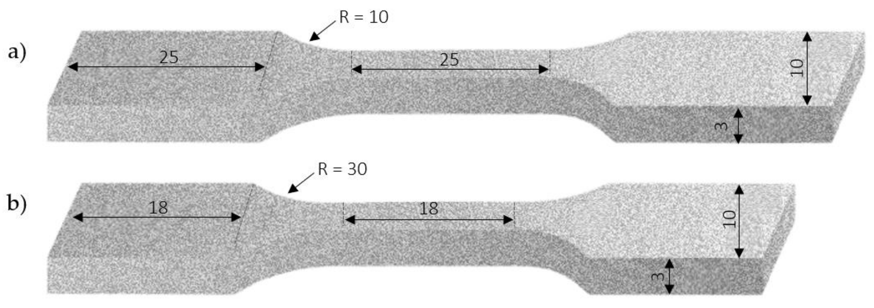
2.1. Material and Specimen Preparation

The material was a hot rolled AZ31B magnesium alloy sheet (composition in wt.% Al 2.54%, Zn 1.08%, Mn 0.38% and Mg balance), supplied by Xi’an Yuechen Metal Products Co. Ltd. (Xi’an, China). The tensile and fatigue samples were machined by laser-cutting along the rolling direction following ASTM E8M-16a [26] and ASTM E466-15 [27], respectively. Figure 1 shows the shape and size of the specimens employed for tensile and fatigue tests. The dog-bone shaped specimens were sequentially ground using waterproof silicon carbide paper (from #220 to #4000), and polished using diamond paste slurry (diameter 3 µm and 1 µm). Right after, they were cleaned using deionized water and ethanol, being dried in a warm air stream provided by a conventional heat gun.
For the corrosion test, the AZ31B magnesium alloy was cut using a cut-off saw in a square section with area of 100 mm2 and thickness of 3.5 mm. The AZ31B alloy pieces were connected to a copper wire at the rear side using a conductive colloidal silver paste, being subsequently embedded in epoxy resin. Next, the surfaces were ground using waterproof silicon carbide paper (from #220 to #2400 grit size), polished using diamond paste (diameter 1 µm), washed using deionized water, and dried in a warm air stream provided by a conventional heat gun.

2.2. Anodizing Treatment

Anodization was performed in an aqueous solution consisting of a mixture of 1.0 M NaOH and 0.5 M Na2SiO3 at a constant current density of 20 mA cm−2 for 5 min at room temperature. Details about the anodizing experiments can be found in our previous work [28].

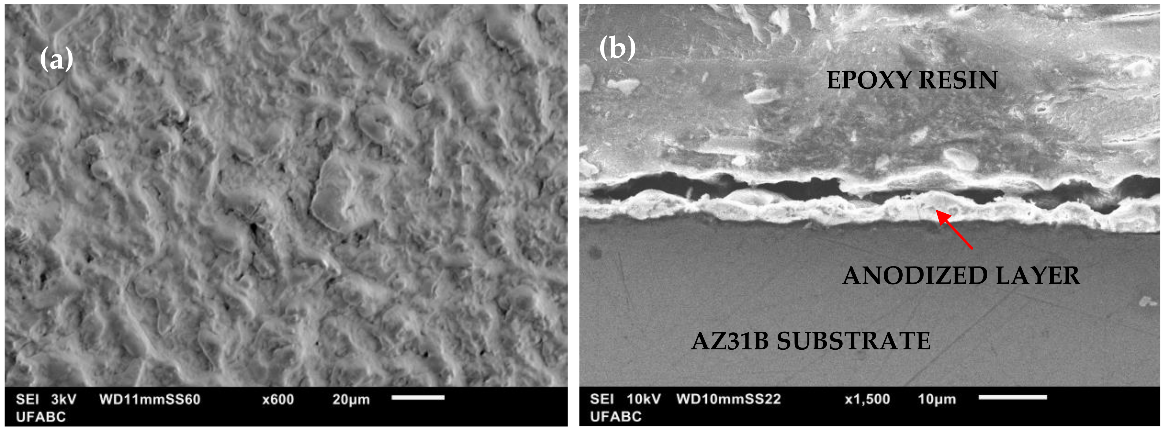
2.3. Coating Morphology and Corrosion Test

The surface and cross-section morphologies of the anodized sample were acquired using scanning electron microscopy (SEM, JSM-6010LA, JEOL, Tokyo, Japan).
The corrosion behavior was assessed in a phosphate-buffered saline (PBS) solution consisting of 0.355 g L−1 NaH2PO4·H2O, 8.2 g L−1 NaCl, and 0.105 g L−1 Na2HPO4 (anhydrous). The electrolyte was prepared with deionized water (18.2 MΩ cm) and analytical grade reagents. The measurements were carried out using a potentiostat/galvanostat (M101, Metrohm Autolab B.V., Utrecht, The Netherlands) in a conventional three-electrode cell configuration. The test cell consisted of a platinum wire as the counter-electrode, Ag/AgCl (3 M, KCl) as the reference and the investigated AZ31B alloy as the working electrode. Firstly, the open potential circuit (OCP) was monitored for 1 h. Next, potentiodynamic polarization tests were conducted in a potential range from −0.50 vs. OCP to 0 V vs. Ag/AgCl/(3 M, KCl), at a scanning rate of 1 mV s−1. The experiments were performed at room temperature and in triplicate.
The porosity of the anodized layer was calculated using an electrochemical relationship based on the assessment of polarization resistance (Rp) values obtained from the potentiodynamic curves. This relationship is based on the variation of the corrosion potential (∆Ecorr = Ecorr, substrateEcorr, substrate + coating) incited by the presence of the coating and from individual measurements of the polarization resistance (Rp) of the polished and anodized AZ31B, according to Equation (1) [28,29].
P = R p , s R p × 10 Δ E c o r r b a
where Rp,s indicates the polarization resistance of the polished AZ31B alloy and Rp is related to the polarization resistance of the anodized AZ31B alloy, ba is the anodic Tafel slope of the bare material. Rp,s and ba are determined from separate analysis of the polished substrate.

2.4. Tensile Test

The tensile tests were carried out following the ASTM E8M-16a [26] at a displacement rate of 12.7 mm/min at room temperature on a universal material testing machine (MTS Exceed E45, Eden Prairie, MN, USA). Five measurements were taken for the AZ31B alloy in the polished and anodized conditions.

2.5. Fatigue and Corrosion Fatigue Tests

Axial fatigue tests were conducted using a computer-controlled servo-hydraulic testing machine (MTS Landmark 370, Eden Prairie, MN, USA) with a sinusoidal loading control. The stress ratio was 0.1 (tension-tension mode) and the test frequency was 5 Hz. The fatigue test was continued until fracture or until the specimen did not fail up to 106 cycles. The procedure was defined according to ASTM F1801-97 [30], which is specific for temporary metal-based implants. Thus, the maximum stress at which the sample has not failed at 106 cycles is defined as a fatigue limit in this work. At every test load condition at least three specimens were evaluated.
The electrolyte employed in the corrosion fatigue tests was phosphate-buffered saline (PBS) solution, which contains: 0.355 g L−1 NaH2PO4·H2O, 8.2 g L−1 NaCl, 0.105 g L−1 Na2HPO4 (anhydrous). The solution was prepared with deionized water and analytical grade reagents. An acrylic chamber was designed and mounted on MTS Landmark 370 servo-hydraulic machine, in order to safeguard the gage length of the specimen was immersed in the PBS during the fatigue test. The electrolyte was subject to room temperature, open to air, and static during the testing procedure. A new fresh solution was employed for each test.

2.6. Fracture Surface Analysis

The fatigue fractured specimens were immersed in 10 g L−1 CrO3 for 5 min in order to remove corrosion products, in agreement to ASTM G1-90 [31]. Next, they were rinsed in deionized water, and dried in warm air stream provided by a conventional heat gun prior to fractographic analysis.
The fractured specimen surface was examined using scanning electron microscopy (SEM, JEOL JSM-6010LA, Tokyo, Japan) and stereomicroscopy (Olympus SZ61, Tokyo, Japan).

3. Results and Discussion

3.1. Anodized Layer Morphology and Corrosion Test

SEM micrographs of the top surface and cross-section of the AZ31B magnesium alloy in the anodized condition are shown in Figure 2. As seen in Figure 2a, the artificial oxide layer produced by the anodization treatment covered the whole substrate. Several cracks and carved regions are unevenly distributed over the surface. The cross section of the anodized specimen is showed in Figure 2b. The interface anodized layer/substrate displays an irregular thickness. A roughened interface greatly affects the design of the implantable devices, once it plays an important role behaving as a stress concentrator [32], thus limiting the fatigue resistance of the component.
Potentiodynamic polarization curves of the polished and anodized samples tested in PBS solution at room temperature are presented in Figure 3. The values of corrosion potential (Ecorr) and corrosion current densities (jcorr) were determined from the curves using the Tafel extrapolation method. The results are shown in Table 1. The jcorr values were significantly affected by the presence of the anodic film. The dissolution rate of the anodized sample was reduced by one order of magnitude. The anodized layer acted as a barrier layer against electrolyte penetration. However, as seen in Table 1, the produced oxide layer presents an inherent porosity, which could be related to the cracks and cavities observed from the SEM micrographs (Figure 2).
In the cathodic branches, the value of the cathodic Tafel slope (bc) was increased after anodization, as shown in Table 1. According to Rahman et al. [33], this effect could be due to the formation of Mg(OH)2 inside the pores and cracks of the anodized layer, as shown in Equations (2) and (3).
2H2O + 2e → H2 + 2OH
Mg2+ + 2OH → Mg(OH)2
When film breakdown occurs in the anodic part of the polarization curve, the possible sequence of reactions is depicted in Equations (4) and (5). These processes (anodic and cathodic reactions) are accompanied by the formation of a corrosion product layer, following the same reaction shown in Equation (3). Furthermore, due to the presence of chloride ions in the PBS solution, Mg(OH)2 could further react according to Equation (6).
Mg → Mg2+ + 2e (anodic dissolution)
2H2O + 2e → H2 + 2OH (cathodic reaction)
Mg(OH)2 + 2Cl → MgCl2 + 2OH

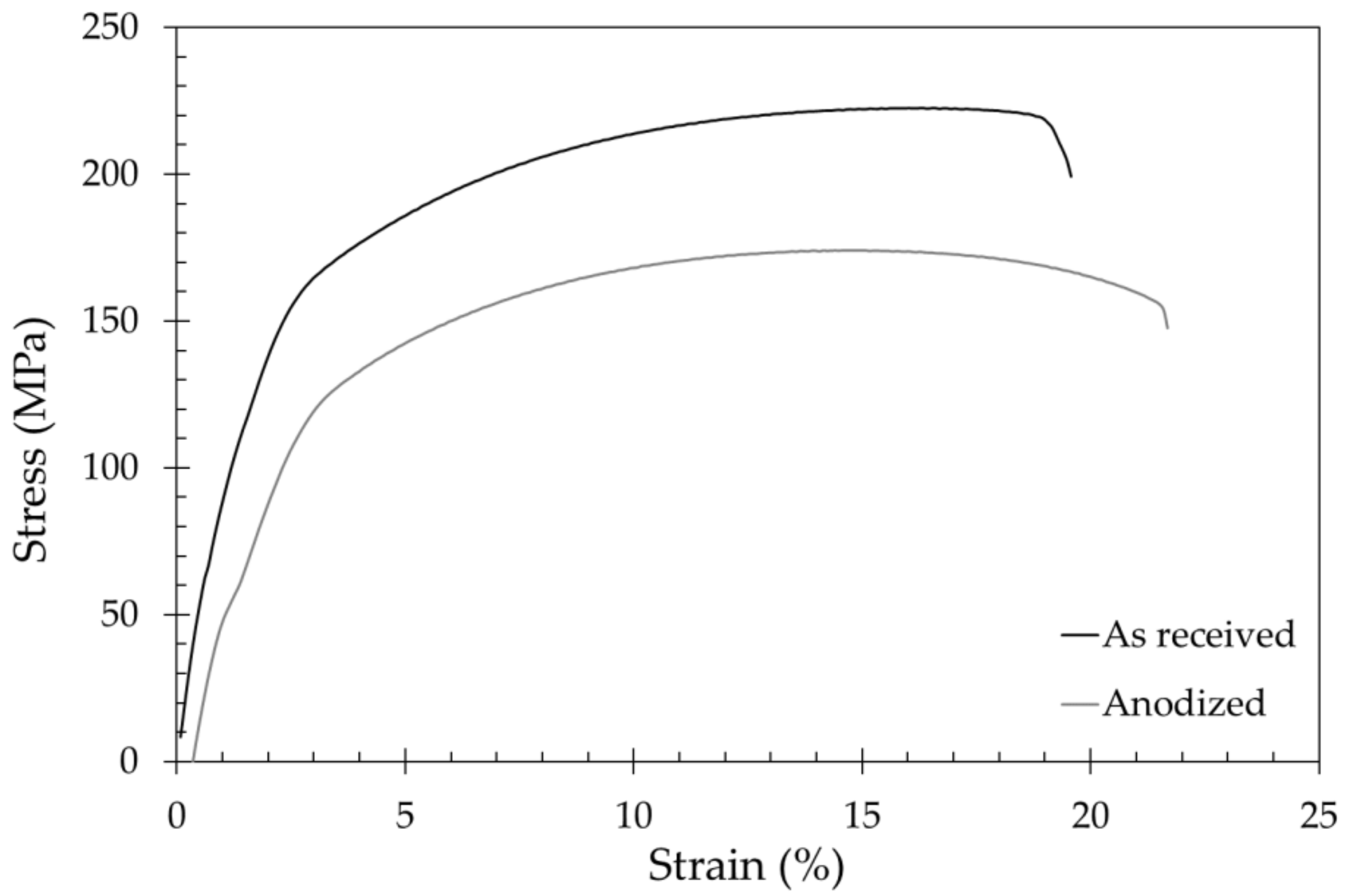
3.2. Tensile Properties

Figure 4 shows the stress–strain curves of the AZ31B magnesium alloy in the as received and anodized conditions. The average values of yield strength, ultimate strength, and elongation at break of the alloy in the as received and anodized conditions are displayed in Table 2. It is clear that the ultimate tensile strength and yield strength decreased after anodization. According to the literature [34], this effect is due to the presence of pores and defects in the oxide layer that act as crack nucleation sites, reducing the mechanical strength of the anodized substrate.

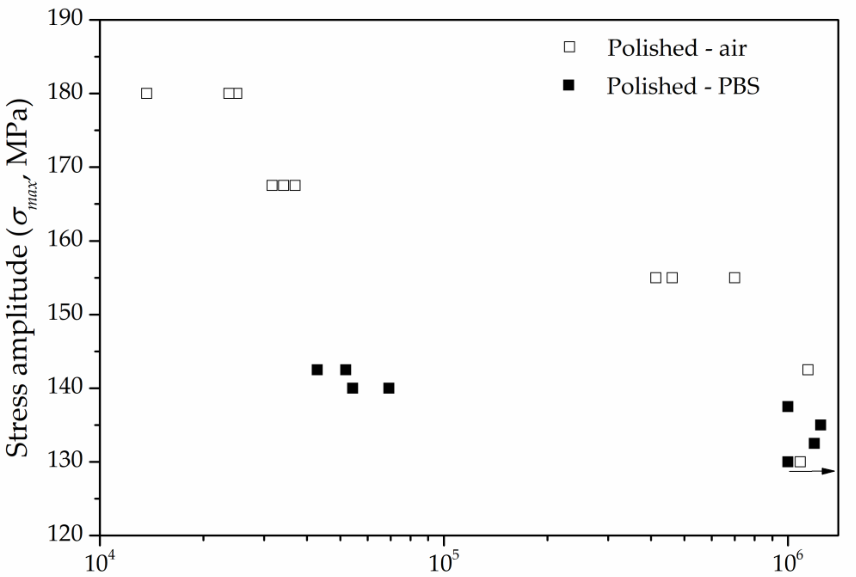
3.3. Fatigue and Corrosion Fatigue Behavior

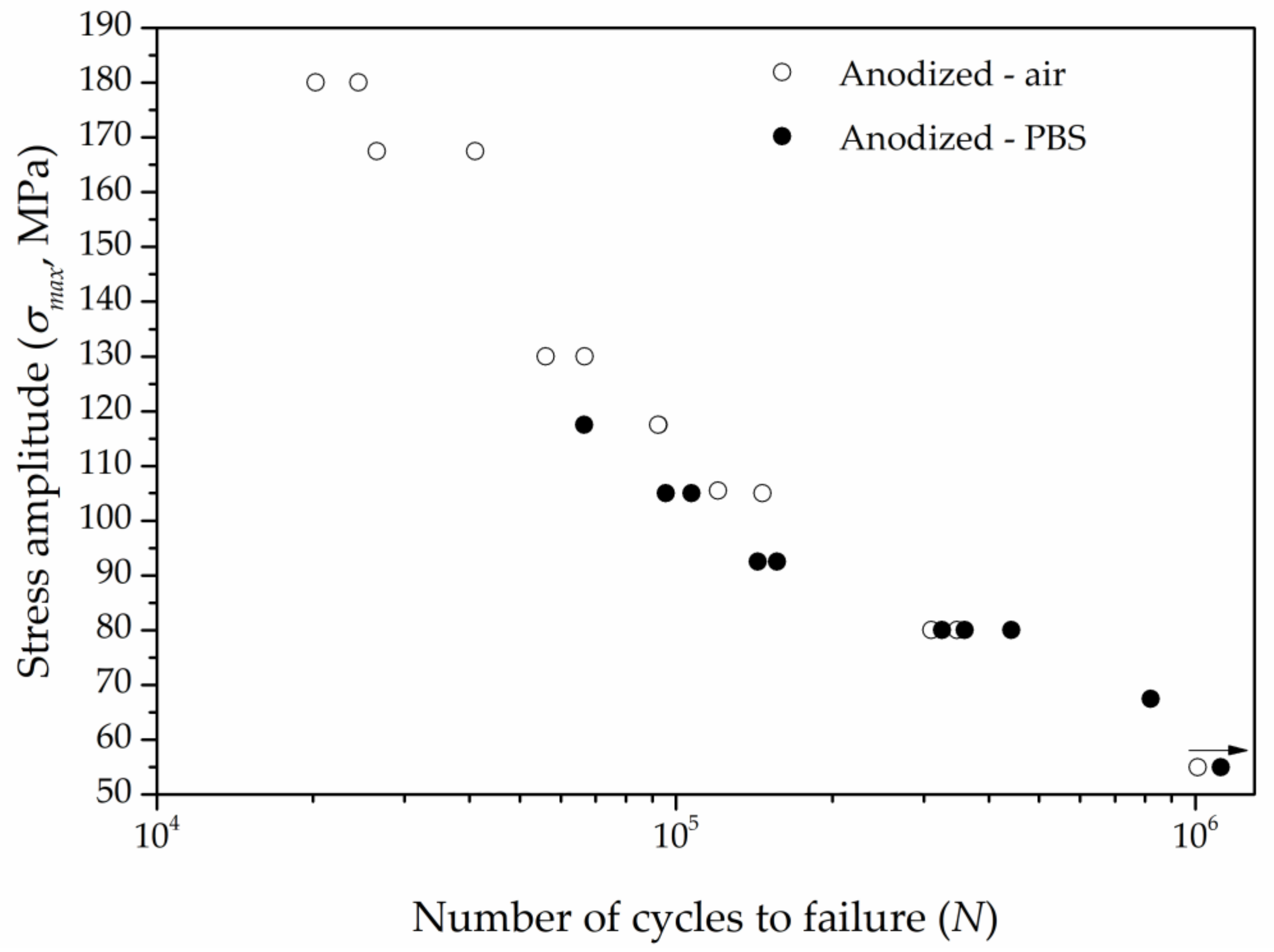
3.3.1. Influence of the Corrosive Environment

Figure 5 presents the S-N curves for the polished AZ31B alloy exposed to the air and to the PBS solution. Comparatively, a decrease on the maximum applied stress is noticed when the tests were performed in the PBS solution. Considering 106 cycles to failure, according to ASTM F1801, the fatigue limit was reduced from 142.5 MPa when the tests were conducted in the air, to 137.5 MPa when the tests were conducted in PBS. However, at an intermediate number of cycles to failure, the influence of the testing environment is even more evident. It can be seen that an applied stress of 140 MPa led to the fatigue life of approximately 69,000 cycles, while the fatigue life was extended to 106 cycles at a compatible applied stress when the tests were conducted in the air. These results indicate that there is an abrupt change in the fatigue life for a relatively low variation of the applied stress in the corrosion-fatigue condition. A similar trend was observed by Nan et al. during fatigue tests of the AZ31 alloy [35]. A slight loading variation was sufficient to drastically reduce the fatigue life of this material. In another work, Nan et al. have also investigated the influence of the 3.5 wt.% NaCl on the corrosion fatigue behavior of the AZ31 alloy [36]. A remarkable decrease in fatigue resistance was noticed when the tests were performed in the chloride solution. Authors have pointed out the combination of cyclic stress and pit growth as responsible for this behavior [37,38].
The S-N curves for the anodized specimens exposed to air and PBS solution are shown in Figure 6. Corrosion was less detrimental for the surface treated samples than the polished ones. As displayed in Figure 5, the fatigue life was little affected by the corrosive environment for stress levels lower than 130 MPa.
In order to give a more quantitative interpretation on the influence of corrosion on the fatigue resistance of the AZ31B alloy, we employed Equations (7) and (8) to calculate the reduction rate (RσN) of the maximum fatigue strength at 106 cycles, as proposed by He et al. [35]. Based on this procedure, fitting equations shown in Table 3 were obtained by a logarithmic transformation of the experimental data points shown in Figure 4 and Figure 5.
y = k + bx
R σ N = σ a i r σ P B S σ a i r × 100
In Equation (2), y and x are log (σmax) and log N, respectively. The maximum applied stress is represented by σmax, while N is the number of cycles to failure at a certain stress level. The parameters k and b are coefficients. In Equation (3), N indicates the reduction rate of the maximum applied stress at specific fatigue cycles in air and in PBS solution. The maximum applied stress that specimens can resist at specific fatigue cycles are denoted by σair and σPBS. Table 4 displays the values of these parameters, along with the corresponding N at 106 cycles.
As seen in Table 4, the reduction rate of the polished AZ31B alloy was 5.6% when immersed in the PBS solution, while the anodized condition, in turn, showed an increment. Therefore, the effect of the PBS solution was less harmful to the fatigue strength of the anodized samples. This behavior is probably associated with the protection ability promoted by the anodization treatment. Generally, the main mechanism related to the corrosion fatigue failure of magnesium and its alloys is pit nucleation and growth [19,32,39]. In this case, the presence of the oxide layer possibly provided a higher local dissolution resistance for the AZ31B alloy.

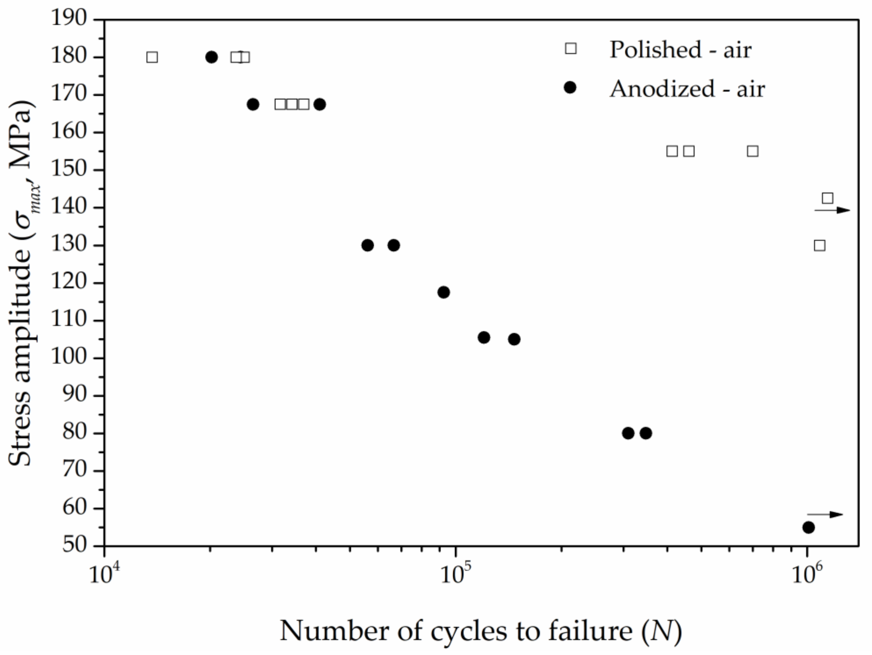
3.3.2. Influence of Anodization

Figure 7 and Figure 8 show the S-N curves for the polished and anodized samples exposed to air and PBS solution, respectively. As seen in these figures, there was a remarkable reduction of the fatigue resistance for the anodized specimens compared to the polished condition regardless of the environment. In both scenarios, the reduction of the fatigue limit at 106 cycles was approximately 60% for the anodized samples.
The reduction of the fatigue strength for the anodized specimens was much more intense at low stress levels, independently of the testing environment. This behavior has been associated to a significant influence of the crack nucleation than the crack propagation, which causes the premature failure of the material [40]. In other words, the anodic layer facilitates fatigue crack nucleation. Khan et al. [41] observed a distinguished effect of the crack nucleation of anodized magnesium alloy when subjected to fatigue tests. The authors concluded that the crack nucleation step, which is defined by the material surface conditions in a crucial manner, exerts more influence than the crack growth and propagation stages. As the anodized layer greatly affects the surface characteristics, this means that fatigue failure would easily happen when a certain number of cycles are able to nucleate the crack. Besides that, other adverse effects concerned with the fatigue behavior of anodized magnesium alloys have been reported in the current literature. Yerochin et al. [42] mentioned that the plasma micro-discharges which occur during the oxidation process led to strain distortions of the metal subsurface layers. Some other works have pointed out the presence of a microcrack network [39] and disordered porous structure [24,32] of the coating layer. Furthermore, the compactness and uniformity of the oxide layer, its adhesion to the substrate, and relevant aspects of roughness on the interface of coating and the material may also affect the fatigue properties of anodized alloys [43,44].
The results obtained in the present work highlighted that the presence of the oxide layer caused a hostile effect to the AZ31B magnesium alloy regardless of the environment conditions.

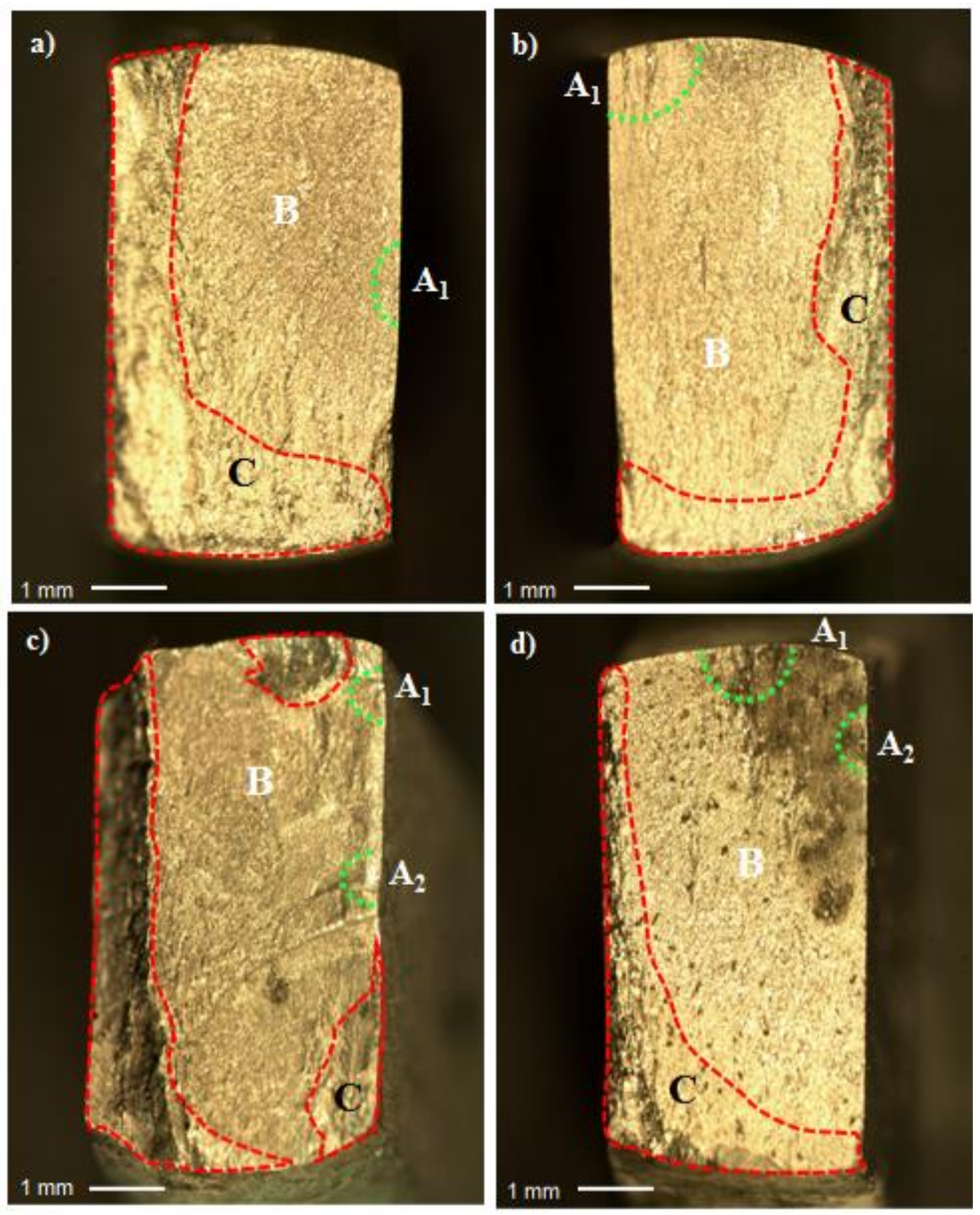
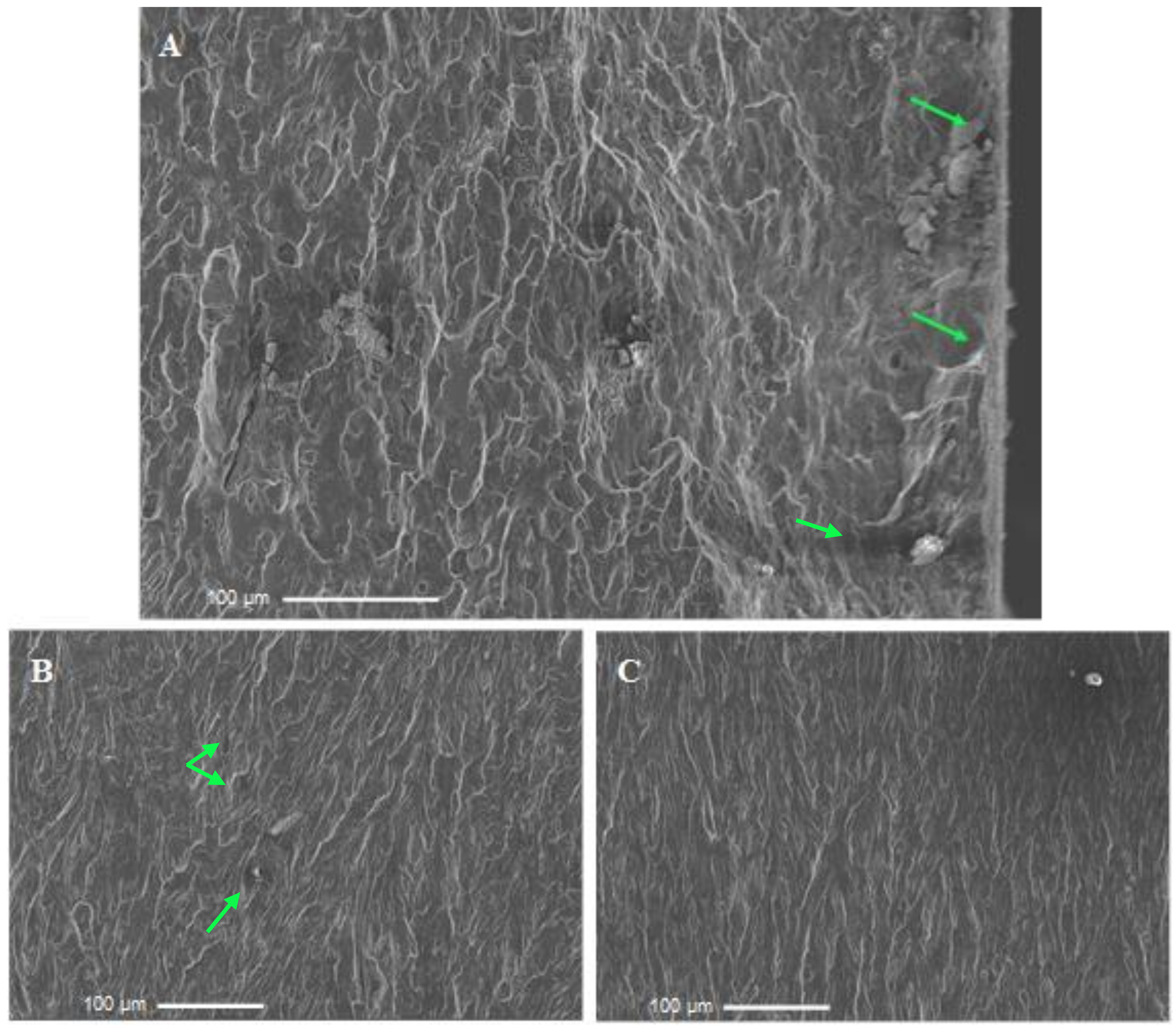
3.4. Fractographic Analysis

Optical stereo-micrographs of the fracture surfaces of polished and anodized AZ31B specimens after fatigue tests in air and PBS solution are shown in Figure 9. The specimens for optical stereoscopic analysis were chosen based on the number of cycles to failure. The aim was to identify the microfractographic features in the initial hours of the test, as it would lead to the most relevant information regarding the nucleation of fatigue cracks. Hence, specimens that failed in the first hours of test, at different applied stresses but with similar fatigue lives were chosen in order to investigate the effect of the PBS solution on the fractographic aspects of the AZ31B alloy. Table 5 displays the applied stress and corresponding number of cycles to failure of the polished and anodized specimens selected for fractographic analysis.
The fatigue fracture surface may display distinguishable regions, denoting three different steps of fatigue failure: (i) crack nucleation; (ii) crack growth and propagation; (iii) catastrophic failure (final fracture) [45,46]. These regions are indicated in Figure 9 for the AZ31B specimens in the polished and anodized conditions. Fatigue fracture is often initiated in the surface or subsurface region [47]. However, identifying the exact point of crack nucleation is not an easy task [48]. These sites are indicated as A1 and A2 in Figure 9. Growth region generally expands radially for the surface of the specimen (region B in Figure 9). The transition from region B to final fracture (region C) is accompanied by a change of the fractographic features to a darker, uneven region. Details regarding each one of these regions were obtained by SEM analysis.
Figure 10 shows the SEM micrographs corresponding to regions A (Figure 10A), B (Figure 10B) and C (Figure 10C) of Figure 9a. Green arrows point to possible crack nucleation sites in Figure 10A, denoted by discontinuities and small particles at the bottom right of the micrographs. However, the nucleation site was not clearly distinguished. A different aspect is seen in the crack growth region (Figure 10B). Faceted regions and shallow dimples are encountered over this region, suggesting an unstable crack growth mechanism was predominant. Conversely, a typical ductile dimpled fracture surface is seen in Figure 10C, suggesting that plastic deformation occurred in this region, before final fracture. Similar features of fractographic aspects of fatigue fracture surfaces of magnesium alloys were reported by other authors [48,49,50,51].
Regions A–C of the fracture surface of the air-tested anodized specimen shown in Figure 9b were further explored by SEM analysis. The corresponding micrographs are displayed in Figure 11. The nucleation region (A1 in Figure 9b) is shown in Figure 11A. Green arrows point to the interface between the anodized layer and the bulk AZ31B alloy, revealing different roughness at these sites. Moreover, subsurface particles are also observed and may have contributed to crack nucleation, as observed by other authors [24,45]. Yet, a gradual transition in the surface appearance from a smooth to a rough aspect is seen at the middle of the micrograph, indicating that crack propagation may have started at this site [52]. In Figure 11B, the crack growth region is further detailed. Its aspect resembles that shown in Figure 9b for the polished sample tested in air, being characterized by faceted regions and shallow dimples, typical of unstable crack growth. In the final fracture region (Figure 11C), the fracture surface is dominated by an intense dimpled structure, indicating plastic deformation at these sites, as also observed in Figure 10C for the polished sample. It is clear, therefore, that anodization did not alter the microfractographic features of the AZ31B alloy subject to fatigue testing in air.
SEM micrographs of regions A1, B, and C (Figure 9c) for the polished sample tested in PBS solution are displayed in Figure 12. The most probable crack nucleation sites (region A1, Figure 9c) are shown in Figure 11A where potential stress risers are pointed by the green arrows, such as discontinuities in the MgO/Mg(OH)2 layer spontaneously formed in the electrolyte and subsurface inclusions that may have facilitated fatigue crack nucleation. The transition between the smooth and rough aspects of the fracture surface is remarkable, as seen in the left part of the micrograph, in contrast with that of the polished samples tested in air (Figure 10A). According to the literature [23,53], this suggests a faster transition from the nucleation step to crack growth. Cracks would appear simultaneously at different sites, triggered by surface porosity or subsurface cracks. Hence, material plasticity is reduced, increasing the crack propagation rate, and leading to rough aspect of the fracture surface. It is likely that the concomitant action of corrosive environment and cyclic loading is responsible for such an enhanced propagation rate. In spite of the surface cleaning step before fractographic analysis, some oxide inclusions still remained in the fracture surface, as indicated by the arrows in Figure 12B,C. The final fracture region (Figure 12C) is similar to those of the specimens tested in air (Figure 10C and Figure 11C), showing a dimpled structure.
SEM micrographs of the fracture surface of the anodized specimen tested in PBS solution are shown in Figure 13. In Figure 13A (region A1 in Figure 9d), green arrows indicate pores, subsurface defects between the substrate and the anodized layer, and inclusions that may be related to crack nucleation by acting as stress risers during fatigue loading. In the crack propagation region (Figure 13B), the fracture surface is quite flat and some micropores are indicated by green arrows. The aspect of the final fracture region (Figure 13C) is quite different from that of the polished sample fractured in PBS (Figure 12C). Instead of a dimpled structure, the surface is flat, indicating that plastic deformation was not as marked as observed for the polished sample. In this respect, it is evident that the presence of the anodized layer reduced plasticity at the final fracture step.
The main observations with respect to the microfractographic features of the fracture surfaces for the AZ31B alloy specimens described in Table 5 are synthesized in Table 6, along with possible causes of the final failure.

4. Conclusions

Anodization displayed a profound effect on the fatigue strength of the AZ31B alloy. S-N curves obtained in the tension-tension mode, in air and PBS solution, indicated that the fatigue limit was reduced by the corrosive electrolyte when the magnesium alloy was tested in the polished condition. Conversely, it increased for the anodized alloy tested in PBS in comparison to the tests conducted in air. However, a reduction of approximately 60% of the fatigue strength was observed for the anodized samples with respect to the polished ones, either in air or PBS solution. The presence of the anodized layer entails remarkable surface changes that affect the fatigue behavior of the AZ31 alloy, mostly related to surface porosity and roughness heterogeneities at the anodized layer/substrate interface. The fracture surface displayed a more brittle character for the anodized alloy fractured in PBS solution when compared to air. Oxide particles are likely to act as stress risers, increasing the crack propagation rate in PBS solution.

Author Contributions

Conceptualization, R.A.A. and L.A.d.O.; Methodlogy, R.A.A. and L.A.d.O.; investigation, L.A.d.O., S.L.d.S. and V.A.d.O.; Writing—original draft preparation, L.A.d.O. and R.A.A.; Supervision, R.A.A.; funding acquisition, R.A.A. All authors have read and agreed to the published version of the manuscript.

Funding

This research was funded by the São Paulo Research Foundation (FAPESP), process number 2015/22921-6 and CAPES (Finance Code 001).

Data Availability Statement

The data obtained in this study are available from the corresponding author on reasonable request.

Acknowledgments

FATEC-SP, DEMa-UFSCar and the Multiuser Experimental Facilities (CEM-UFABC) are acknowledged for the experimental support.

Conflicts of Interest

The authors declare no conflict of interest.

References

  1. Esmaily, M.; Svensson, J.E.; Fajardo, S.; Birbilis, N.; Frankel, G.S.; Virtanen, S.; Arrabal, R.; Thomas, S.; Johansson, L.G. Fundamentals and advances in magnesium alloy corrosion. Prog. Mater. Sci. 2017, 89, 92–193. [Google Scholar] [CrossRef]
  2. Si, Y.; Xiong, Z.; Zheng, X.; Li, M.; Yang, Q. Improving the anti-corrosion ability of anodization film of AZ31B magnesium alloy by addition of NH4VO3 in the electrolyte. Int. J. Electrochem. Sci. 2016, 11, 3261–3268. [Google Scholar] [CrossRef]
  3. Song, G.L.; Shi, Z. Corrosion mechanism and evaluation of anodized magnesium alloys. Corros. Sci. 2014, 85, 126–140. [Google Scholar] [CrossRef] [Green Version]
  4. Cui, L.; Liu, Z.; Hu, P.; Shao, J.; Li, X.; Du, C.; Jiang, B. The corrosion behavior of AZ91D magnesium alloy in simulated haze aqueous solution. Materials 2018, 11, 970. [Google Scholar] [CrossRef] [PubMed] [Green Version]
  5. Mousa, H.M.; Hussein, K.H.; Woo, H.M.; Park, C.H.; Kim, C.S. One-step anodization deposition of anticorrosive bioceramic compounds on AZ31B magnesium alloy for biomedical application. Ceram. Int. 2015, 41, 10861–10870. [Google Scholar] [CrossRef]
  6. Wang, B.J.; Wang, S.D.; Xu, D.K.; Han, E.H. Recent progress in fatigue behavior of Mg alloys in air and aqueous media: A review. J. Mater. Sci. Technol. 2017, 33, 1075–1086. [Google Scholar] [CrossRef]
  7. Yang, Y.; He, C.; Dianyu, E.; Yang, W.; Qi, F.; Xie, D.; Shen, L.; Peng, S.; Shuai, C. Mg bone implant: Features, developments and perspectives. Mater. Des. 2020, 185, 108259. [Google Scholar] [CrossRef]
  8. Sezer, N.; Evis, Z.; Kayhan, S.M.; Tahmasebifar, A.; Koç, M. Review of magnesium-based biomaterials and their applications. J. Magnes. Alloy. 2018, 6, 23–43. [Google Scholar] [CrossRef]
  9. Radha, R.; Sreekanth, D. Insight of magnesium alloys and composites for orthopedic implant applications—A review. J. Magnes. Alloy. 2017, 5, 286–312. [Google Scholar] [CrossRef]
  10. Nassif, N.; Ghayad, I. Corrosion protection and surface treatment of magnesium alloys used for orthopedic applications. Adv. Mater. Sci. Eng. 2013, 2013, 532896. [Google Scholar] [CrossRef] [Green Version]
  11. Uddin, M.S.; Hall, C.; Murphy, P. Surface treatments for controlling corrosion rate of biodegradable Mg and Mg-based alloy implants. Sci. Technol. Adv. Mater. 2015, 16, 53501. [Google Scholar] [CrossRef] [Green Version]
  12. Cheng, I.C.; Fu, E.G.; Liu, L.D.; Lee, C.Y.; Lin, C.S. Effect of Fluorine Anions on Anodizing Behavior of AZ91 Magnesium Alloy in Alkaline Solutions. J. Electrochem. Soc. 2008, 155, C219–C225. [Google Scholar] [CrossRef]
  13. Chai, L.; Yu, X.; Yang, Z.; Wang, Y.; Okido, M. Anodizing of magnesium alloy AZ31 in alkaline solutions with silicate under continuous sparking. Corros. Sci. 2008, 50, 3274–3279. [Google Scholar] [CrossRef]
  14. Li, L.L.; Cheng, Y.L.; Wang, H.M.; Zhang, Z. Anodization of AZ91 magnesium alloy in alkaline solution containing silicate and corrosion properties of anodized films. Trans. Nonferrous Met. Soc. China 2008, 18, 722–727. [Google Scholar] [CrossRef]
  15. Girón, L.; Aperador, W.; Tirado, L.; Franco, F.; Caicedo, J.C. Electrochemical Performance Estimation of Anodized AZ31B Magnesium Alloy as Function of Change in the Current Density. J. Mater. Eng. Perform. 2017, 26, 3710–3718. [Google Scholar] [CrossRef]
  16. Salami, B.; Afshar, A.; Mazaheri, A. The effect of sodium silicate concentration on microstructure and corrosion properties of MAO-coated magnesium alloy AZ31 in simulated body fluid. J. Magnes. Alloy. 2014, 2, 72–77. [Google Scholar] [CrossRef] [Green Version]
  17. De Oliveira, L.A.; Silva, R.M.P.; Antunes, R.A. Scanning Electrochemical Microscopy (SECM) Study of the Electrochemical Behavior of Anodized AZ31B Magnesium Alloy in Simulated Body Fluid. Mater. Res. 2019, 22, 1–8. [Google Scholar] [CrossRef]
  18. Niinomi, M. Fatigue characteristics of metallic biomaterials. Int. J. Fatigue 2007, 29, 992–1000. [Google Scholar] [CrossRef]
  19. Jafari, S.; Singh Raman, R.K.; Davies, C.H.J. Corrosion fatigue of a magnesium alloy in modified simulated body fluid. Eng. Fract. Mech. 2015, 137, 2–11. [Google Scholar] [CrossRef]
  20. Liu, M.; Wang, J.; Zhu, S.; Zhang, Y.; Sun, Y.; Wang, L.; Guan, S. Corrosion fatigue of the extruded Mg–Zn–Y–Nd alloy in simulated body fluid. J. Magnes. Alloy. 2020, 8, 231–240. [Google Scholar] [CrossRef]
  21. Gu, X.N.; Zhou, W.R.; Zheng, Y.F.; Cheng, Y.; Wei, S.C.; Zhong, S.P.; Xi, T.F.; Chen, L.J. Corrosion fatigue behaviors of two biomedical Mg alloys—AZ91D and WE43—In simulated body fluid. Acta Biomater. 2010, 6, 4605–4613. [Google Scholar] [CrossRef]
  22. Bian, D.; Zhou, W.; Liu, Y.; Li, N.; Zheng, Y.; Sun, Z. Fatigue behaviors of HP-Mg, Mg–Ca and Mg–Zn–Ca biodegradable metals in air and simulated body fluid. Acta Biomater. 2016, 41, 351–360. [Google Scholar] [CrossRef]
  23. Eifert, A.J.; Thomas, J.P.; Rateick, R.G. Influence of anodization on the fatigue life of WE43A-T6 magnesium. Scr. Mater. 1999, 40, 929–935. [Google Scholar] [CrossRef]
  24. Khan, S.A.; Miyashita, Y.; Mutoh, Y. Corrosion fatigue behavior of AM60 magnesium alloy with anodizing layer and chemical-conversion-coating layer. Mater. Corros. 2015, 66, 940–948. [Google Scholar] [CrossRef]
  25. Němcová, A.; Skeldon, P.; Thompson, G.E.; Morse, S.; Čížek, J.; Pacal, B. Influence of plasma electrolytic oxidation on fatigue performance of AZ61 magnesium alloy. Corros. Sci. 2014, 82, 58–66. [Google Scholar] [CrossRef]
  26. ASTM E8M-16a. Standard test methods for tension testing of metallic materials 1. ASTM Stand. 2010, 4, 1–27. [Google Scholar] [CrossRef]
  27. ASTM E466-15. Standard Practice for Conducting Force Controlled Constant Amplitude Axial Fatigue Tests of Metallic Materials. ASTM Stand. 2002, 3, 4–8. [Google Scholar] [CrossRef]
  28. De Oliveira, L.A.; Silva, R.M.P.; Rodas, A.C.D.; Souto, R.M.; Antunes, R.A. Surface chemistry, film morphology, local electrochemical behavior and cytotoxic response of anodized AZ31B magnesium alloy. J. Mater. Res. Technol. 2020, 9, 14754–14770. [Google Scholar] [CrossRef]
  29. De Oliveira, M.C.L.; Pereira, V.S.M.; Correa, O.V.; Antunes, R.A. Corrosion performance of anodized AZ91D magnesium alloy: Effect of the anodizing potential on the film structure and corrosion behavior. J. Mater. Eng. Perform. 2014, 23, 593–603. [Google Scholar] [CrossRef]
  30. ASTM F1801-97. Standard Practice for Corrosion Fatigue Testing of Metallic Implant Materials 1. ASTM Stand. 2014, 3, 5–10. [Google Scholar] [CrossRef]
  31. ASTM G1-90. Standard Practice for Preparing, Cleaning, and Evaluation Corrosion Test Specimens. ASTM Stand. 2003, 8, 1–9. [Google Scholar] [CrossRef]
  32. Khan, S.A.; Miyashita, Y.; Mutoh, Y.; Koike, T. Effect of anodized layer thickness on fatigue behavior of magnesium alloy. Mater. Sci. Eng. A 2008, 474, 261–269. [Google Scholar] [CrossRef]
  33. Rahman, Z.U.; Deen, K.M.; Haider, W. Controlling corrosiion kinetics of magnesium alloys by electrochemical anodization and investigation of film mechanical properties. Appl. Surf. Sci. 2019, 484, 906–916. [Google Scholar] [CrossRef]
  34. Barjaktarevic, D.; Medjo, B.; Gubeljak, N.; Cvijovic-Alagic, I.; Stefane, P.; Djokic, V.; Rakin, M. Experimental and numerical analysis of tensile properties of Ti-13Nb-13Zr alloy and determination of influence of anodization process. Proc. Struct. Integr. 2020, 28, 2187–2194. [Google Scholar]
  35. Nan, Z.Y.; Ishihara, S.; McEvily, A.J.; Shibata, H.; Komano, K. On the sharp bend of the S-N curve and the crack propagation behavior of extruded magnesium alloy. Scr. Mater. 2007, 56, 649–652. [Google Scholar] [CrossRef]
  36. Nan, Z.Y.; Ishihara, S.; Goshima, T. Corrosion fatigue behavior of extruded magnesium alloy AZ31 in sodium chloride solution. Int. J. Fatigue 2008, 30, 1181–1188. [Google Scholar] [CrossRef]
  37. He, X.L.; Wei, Y.H.; Hou, L.F.; Yan, Z.F.; Guo, C.L. High-frequency corrosion fatigue behavior of AZ31 magnesium alloy in different environments. Proc. Inst. Mech. Eng. Part C J. Mech. Eng. Sci. 2013, 228, 1645–1657. [Google Scholar] [CrossRef]
  38. Bhuiyan, M.S.; Mutoh, Y.; Murai, T.; Iwakami, S. Corrosion fatigue behavior of extruded magnesium alloy AZ61 under three different corrosive environments. Int. J. Fatigue 2008, 30, 1756–1765. [Google Scholar] [CrossRef]
  39. Raman, S.R.K.; Jafari, S.; Harandi, S.E. Corrosion fatigue fracture of magnesium alloys in bioimplant applications: A review. Eng. Fract. Mech. 2015, 137, 97–108. [Google Scholar] [CrossRef]
  40. Hilpert, M.; Wagner, L. Corrosion fatigue behavior of the high-strength magnesium alloy AZ 80. J. Mater. Eng. Perform. 2000, 9, 402–407. [Google Scholar] [CrossRef]
  41. Khan, S.A.; Miyashita, Y.; Mutoh, Y.; Koike, T. Fatigue behavior of anodized AM60 magnesium alloy under humid environment. Mater. Sci. Eng. A 2008, 498, 377–383. [Google Scholar] [CrossRef]
  42. Yerokhin, A.L.; Shatrov, A.; Samsonov, V.; Shashkov, P.; Leyland, A.; Matthews, A. Fatigue properties of Keronite® coatings on a magnesium alloy. Surf. Coat. Technol. 2004, 182, 78–84. [Google Scholar] [CrossRef]
  43. Ceschini, L.; Morri, A.; Angelini, V.; Messieri, S. Fatigue behavior of the rare earth rich EV31A Mg alloy: Influence of plasma electrolytic oxidation. Metals 2017, 7, 212. [Google Scholar] [CrossRef]
  44. Lonyuk, B.; Apachitei, I.; Duszczyk, J. The effect of oxide coatings on fatigue properties of 7475-T6 aluminium alloy. Surf. Coat. Technol. 2007, 201, 8688–8694. [Google Scholar] [CrossRef]
  45. Wang, B.J.; Xu, D.K.; Wang, S.D.; Sheng, L.Y.; Zeng, R.C.; Han, E. hou Influence of solution treatment on the corrosion fatigue behavior of an as-forged Mg-Zn-Y-Zr alloy. Int. J. Fatigue 2019, 120, 46–55. [Google Scholar] [CrossRef]
  46. Wang, S.D.; Xu, D.K.; Wang, B.J.; Han, E.H.; Dong, C. Effect of corrosion attack on the fatigue behavior of an as-cast Mg-7%Gd-5%Y-1%Nd-0.5%Zr alloy. Mater. Des. 2015, 84, 185–193. [Google Scholar] [CrossRef]
  47. Xu, D.K.; Liu, L.; Xu, Y.B.; Han, E.H. The crack initiation mechanism of the forged Mg-Zn-Y-Zr alloy in the super-long fatigue life regime. Scr. Mater. 2007, 56, 1–4. [Google Scholar] [CrossRef]
  48. Yang, Y.; Liu, Y.B. High cycle fatigue characterization of two die-cast magnesium alloys. Mater. Charact. 2008, 59, 567–570. [Google Scholar] [CrossRef]
  49. Lv, F.; Yang, F.; Duan, Q.Q.; Yang, Y.S.; Wu, S.D.; Li, S.X.; Zhang, Z.F. Fatigue properties of rolled magnesium alloy (AZ31) sheet: Influence of specimen orientation. Int. J. Fatigue 2011, 33, 672–682. [Google Scholar] [CrossRef]
  50. Ochi, Y.; Masaki, K.; Hirasawa, T.; Wu, X.; Matsumura, T.; Takigawa, Y.; Higashi, K. High cycle fatigue property and micro crack propagation behavior in extruded AZ31 magnesium alloys. Mater. Trans. 2006, 47, 989–994. [Google Scholar] [CrossRef] [Green Version]
  51. Tokaji, K.; Kamakura, M.; Ishiizumi, Y.; Hasegawa, N. Fatigue behaviour and fracture mechanism of a rolled AZ31 magnesium alloy. Int. J. Fatigue 2004, 26, 1217–1224. [Google Scholar] [CrossRef]
  52. Rivers, G. Cyclic Fatigue Behaviour of Wrought AZ80 Magnesium Alloy from Forged Automotive Wheel. Ph.D. Thesis, McMaster University, Hamilton, ON, Canada, 2011. [Google Scholar]
  53. Fouad, Y. Fatigue behavior of a rolled AZ31 magnesium alloy after surface treatment by EP and BB conditions. Alex. Eng. J. 2011, 50, 23–27. [Google Scholar] [CrossRef] [Green Version]
Figure 1. Shape and dimensions (in mm) of (a) tensile and (b) fatigue specimens.
Metals 11 01573 g001
Figure 2. SEM images of the anodized layer (a) top surface and (b) cross-section.
Metals 11 01573 g002
Figure 3. Potentiodynamic polarization curves obtained for the as polished and anodized samples immersed in PBS solution at room temperature.
Metals 11 01573 g003
Figure 4. Stress-strain curves in uniaxial tensile tests at room temperature.
Metals 11 01573 g004
Figure 5. S-N curves for the polished AZ31B alloy specimens in air and in PBS solution at room temperature.
Metals 11 01573 g005
Figure 6. S-N curves for the anodized AZ31B alloy specimens in air and in PBS solution at room temperature.
Metals 11 01573 g006
Figure 7. S-N curves for the polished and anodized AZ31B alloy specimens in air.
Metals 11 01573 g007
Figure 8. S-N curves for the polished and anodized AZ31B alloy specimens in the PBS solution at room temperature.
Metals 11 01573 g008
Figure 9. Optical stereo-micrographs of the AZ31B alloy: (a) polished (air; 167.5 MPa); (b) anodized (air—105 MPa); (c) polished (PBS solution—140 MPa); and (d) anodized (PBS solution—92.5 MPa). Marks on the micrographs represent the following fracture regions: (A1 and A2) crack initiation; (B) crack propagation; (C) catastrophic failure.
Metals 11 01573 g009
Figure 10. Fatigue fracture morphologies of the polished specimen tested in air at 167.5 MPa. The micrographs (AC) correspond to the three different regions pointed out in Figure 9a.
Metals 11 01573 g010
Figure 11. Fatigue fracture morphologies of the anodized specimen tested in air at 105 MPa. The micrographs (AC) correspond to the three different regions pointed out in Figure 9b.
Metals 11 01573 g011
Figure 12. Fatigue fracture morphologies of the polished specimen tested in PBS solution at 140 MPa. The micrographs (AC) correspond to the three different regions pointed out in the Figure 9c.
Metals 11 01573 g012
Figure 13. Fatigue fracture morphologies of the anodized specimen tested in the PBS solution at 92.5 MPa at room temperature. The images (AC) correspond to the three different regions pointed out in the Figure 9d.
Metals 11 01573 g013
Table 1. Electrochemical parameters obtained from the potentiodynamic polarization curves displayed in Figure 2. The last column indicates the porosity percentage of the anodized sample.
ConditionEcorrjcorrRpbaAZ31B|bc|P
(V vs. Ag/AgCl/(3 M) KCl)(μA cm−2)(kΩ cm2)(mV dec−1)(mV dec−1)(%)
As polished−1.407 ± 0.00430.4 ± 8.50.71100130-
Anodized−1.470 ± 0.0412.0 ± 0.751.2-1600.84
Table 2. Stress-strain curves in uniaxial tension tests at room temperature for anodized and as received specimens.
SpecimensUltimate Tensile Strength (MPa)Yield Strength (MPa)Elongation (%)
As received223 ± 5165 ± 520 ± 3
Anodized175 ± 5120 ± 520 ± 3
Table 3. Fitting equations for each experimental condition.
Specimen Conditions and EnvironmentEquations
Polished–airlog(σmax) = −7894lnN + 254.61
Polished – PBS solutionlog(σmax) = −1336lnN + 155.86
Anodized–airlog(σmax) = −32,96lnN + 501.26
Anodized–PBS solutionlog(σmax) = −20,39lnN + 340.47
Table 4. Reduction rate of the maximum applied stress for the AZ31B alloy in the polished and anodized conditions.
Conditionsσair (MPa)σPBS (MPa)N (%)
Polished144.6137.45.6
Anodized45.958.8−28.0
Table 5. Specimens chosen for fracture analysis after the corrosion fatigue tests.
Corrosion Fatigue ResultsPolishedAnodized
AirPBS SolutionAirPBS Solution
Applied stress (MPa)167.514010592.5
Number of cycles to failure34,20054,355146,754143,681
Table 6. Summary of characteristics of the fractured specimens submitted to the corrosion fatigue tests.
ConditionsCrack StatusPossible CausesFracture Appearance
Polished—Air
Figure 8
Single crack nucleationSurface and subsurface discontinuitiesBrittle with radial pattern
Anodized—Air
Figure 8
Single crack nucleationRough or uneven anodized layerBrittle with radial pattern
Polished—PBS solution
Figure 8
Multiple crack nucleationSurface and subsurface discontinuities combined with local corrosionBrittle and hackly types
Anodized—PBS solution
Figure 8
Multiple crack nucleationRough or uneven anodized layerBrittle and quasi-cleavage types
Publisher’s Note: MDPI stays neutral with regard to jurisdictional claims in published maps and institutional affiliations.

