
Tribological Behavior of Boronized Fe40Mn20Cr20Ni20 High-Entropy Alloys


Abstract
:1. Introduction
2. Materials and Methods
2.1. Materials Preparation
2.2. Friction and Wear Test
2.3. Mechanical Characterization
3. Results and Discussion
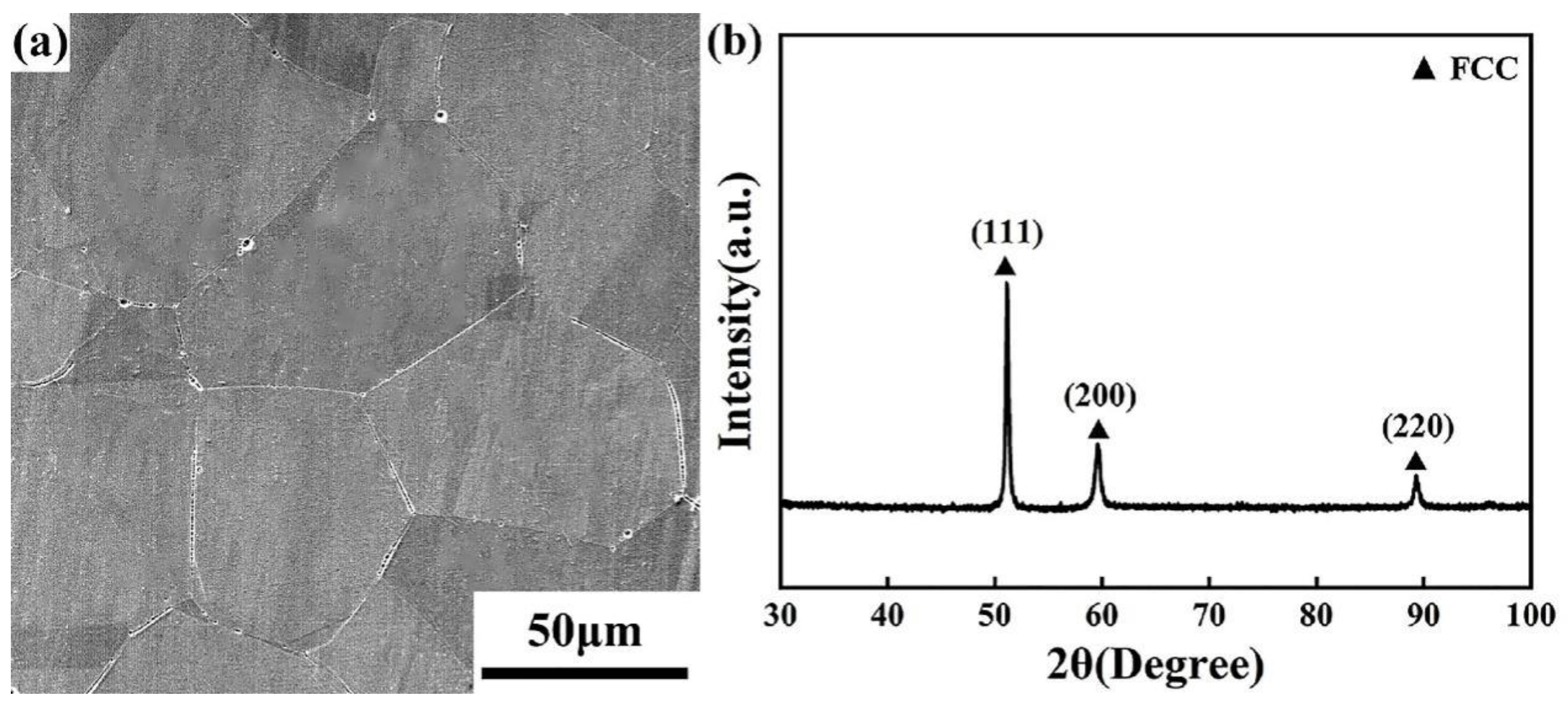
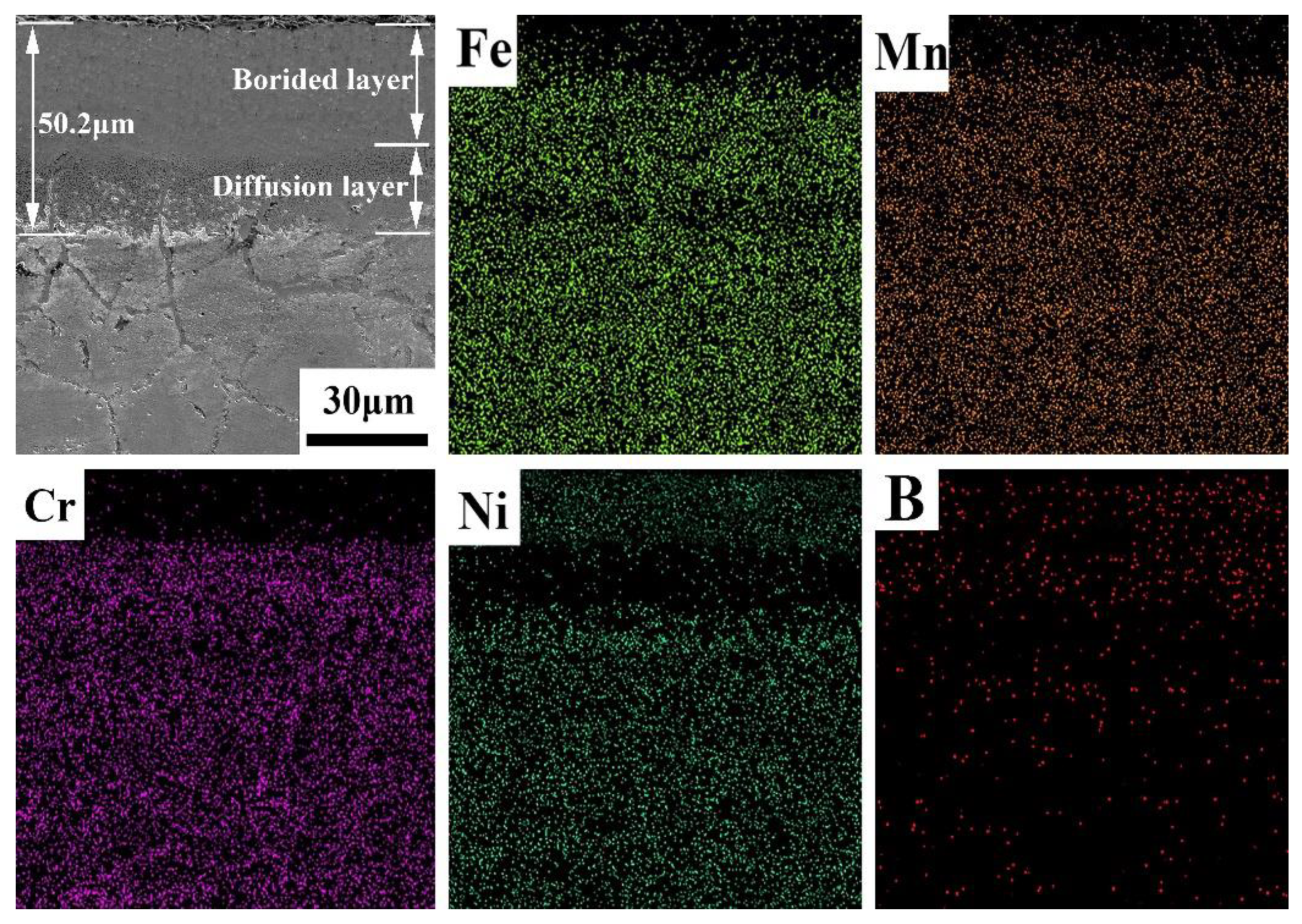
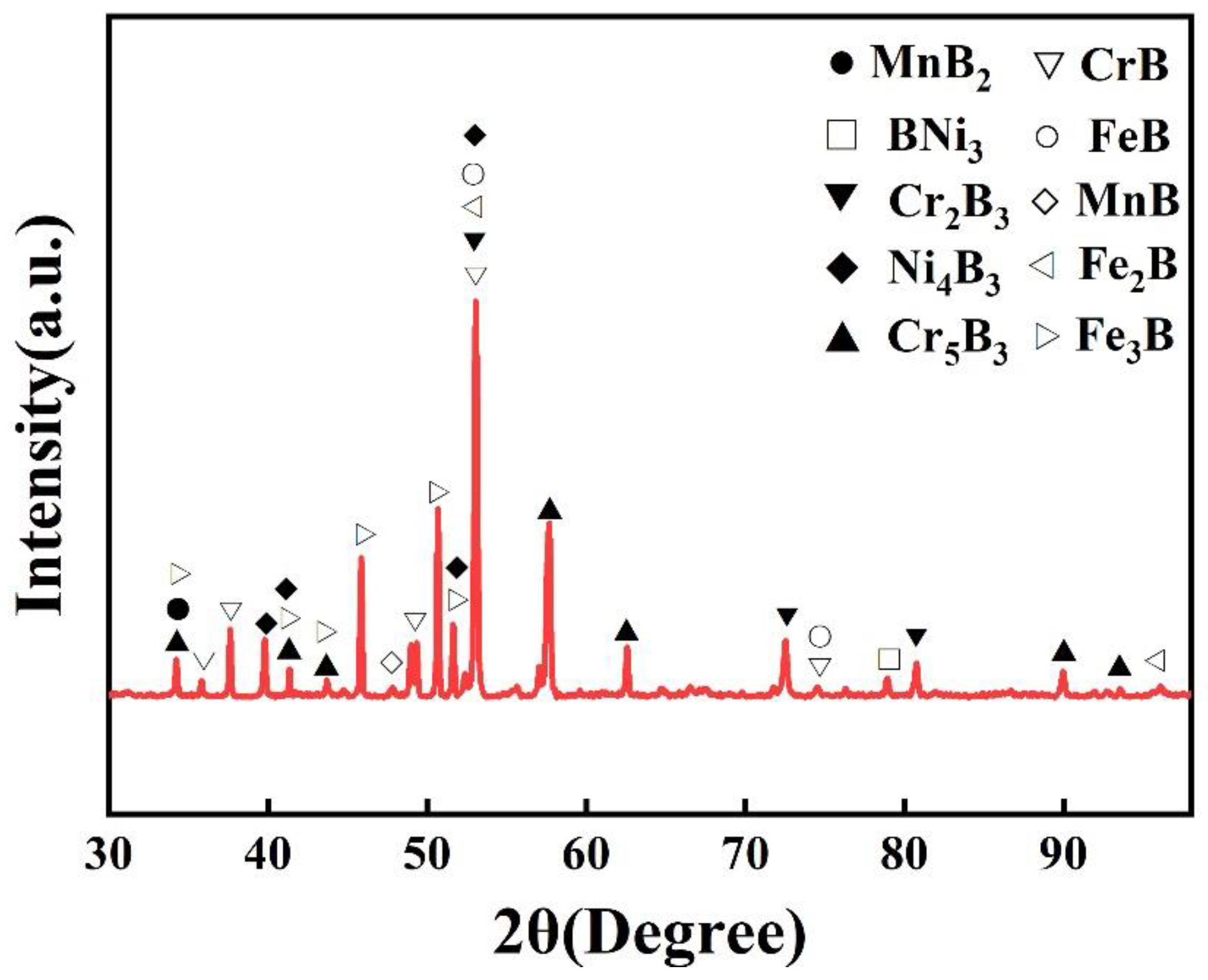
3.1. Microstructures
3.2. Microhardness
3.3. Wear Behavior
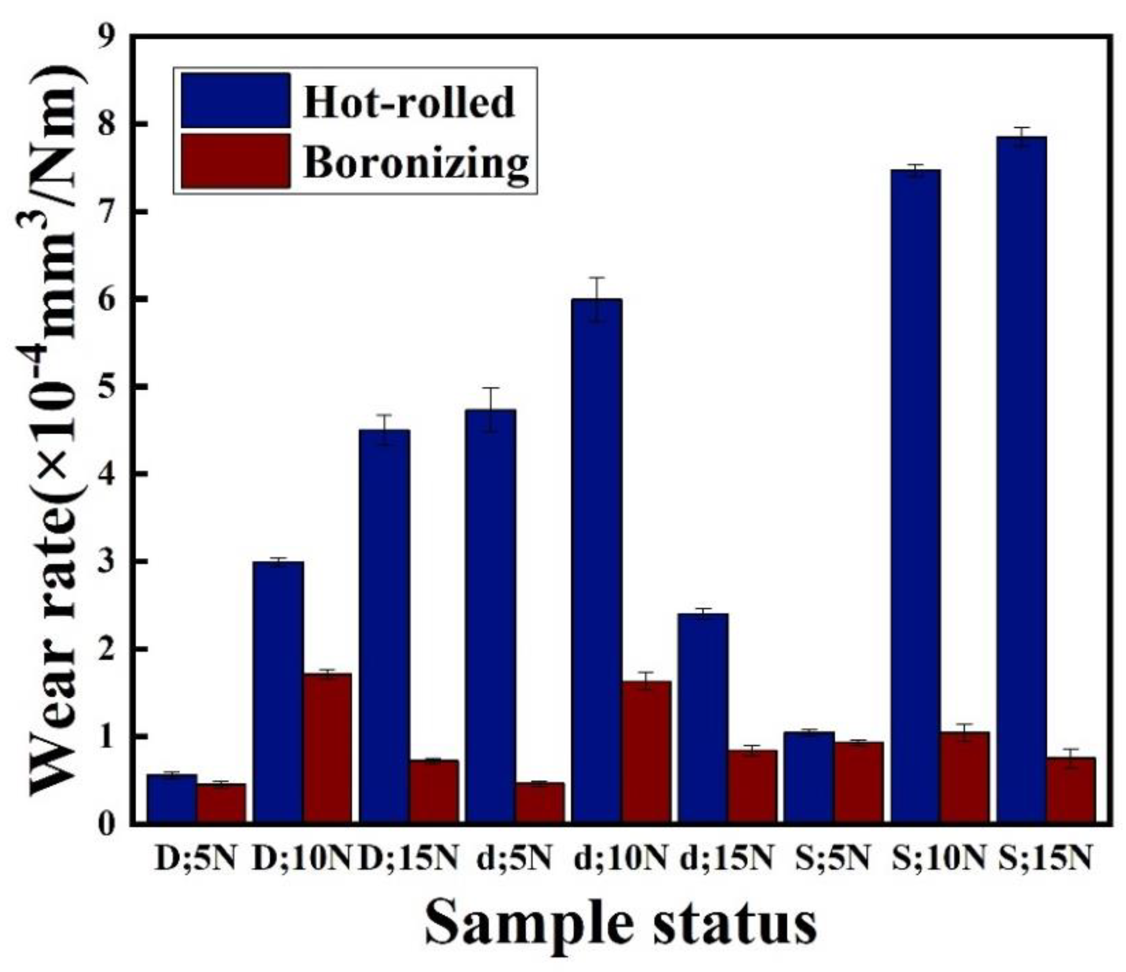
3.3.1. Wear Rate
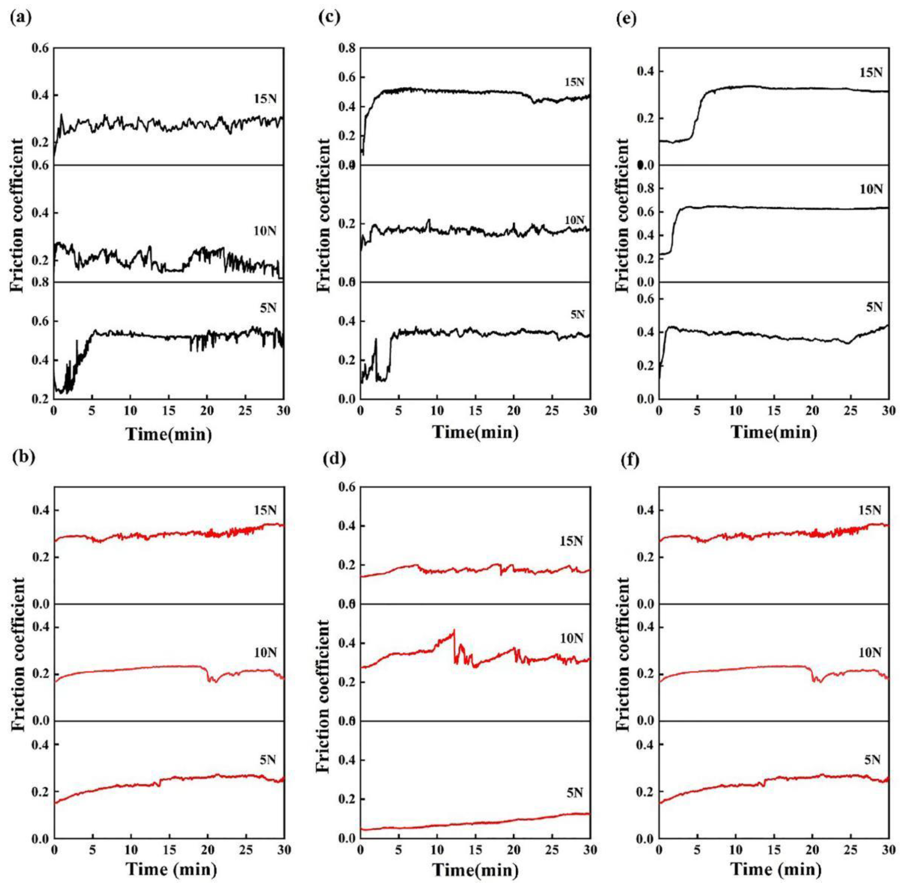
3.3.2. Friction Coefficient
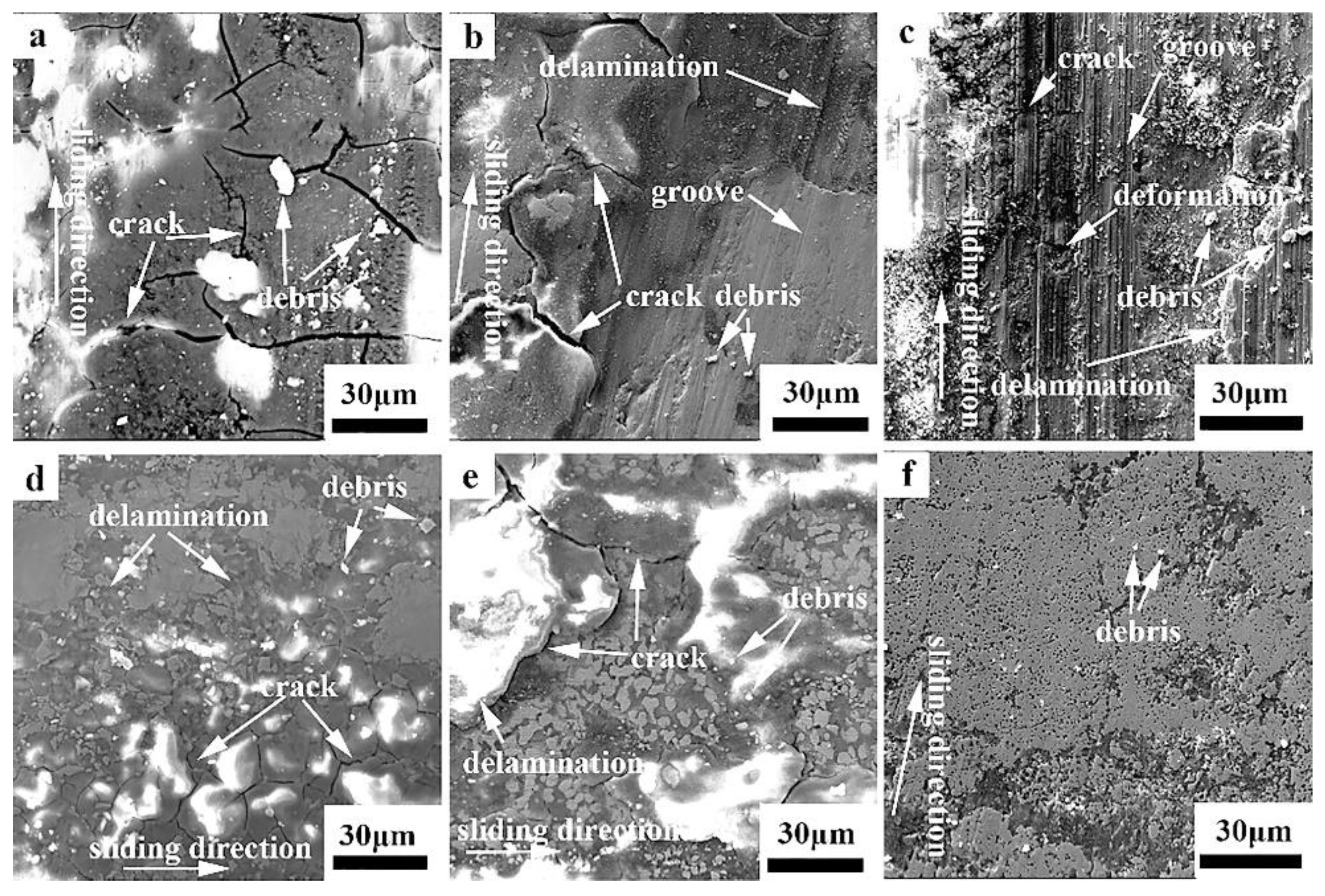
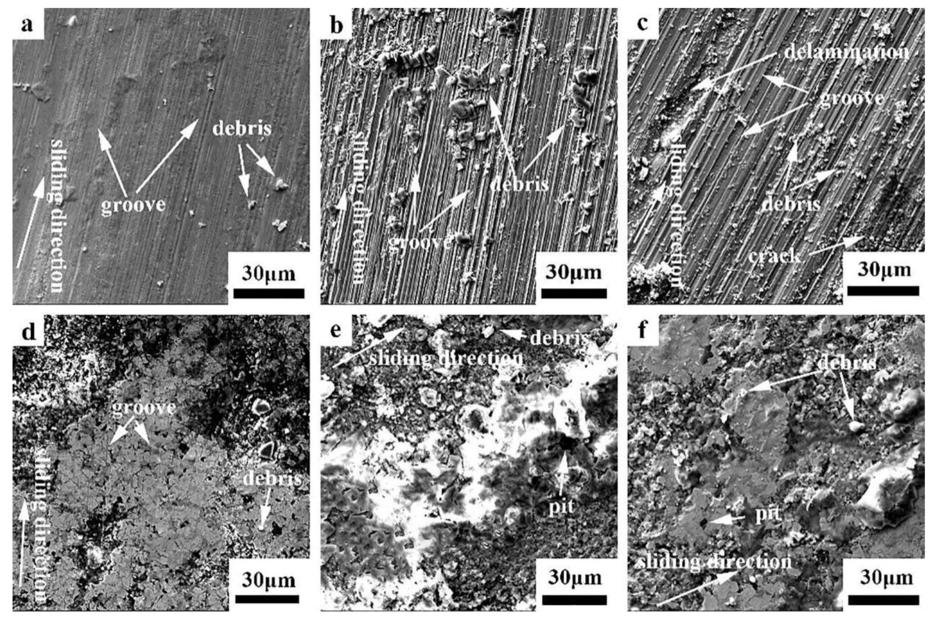
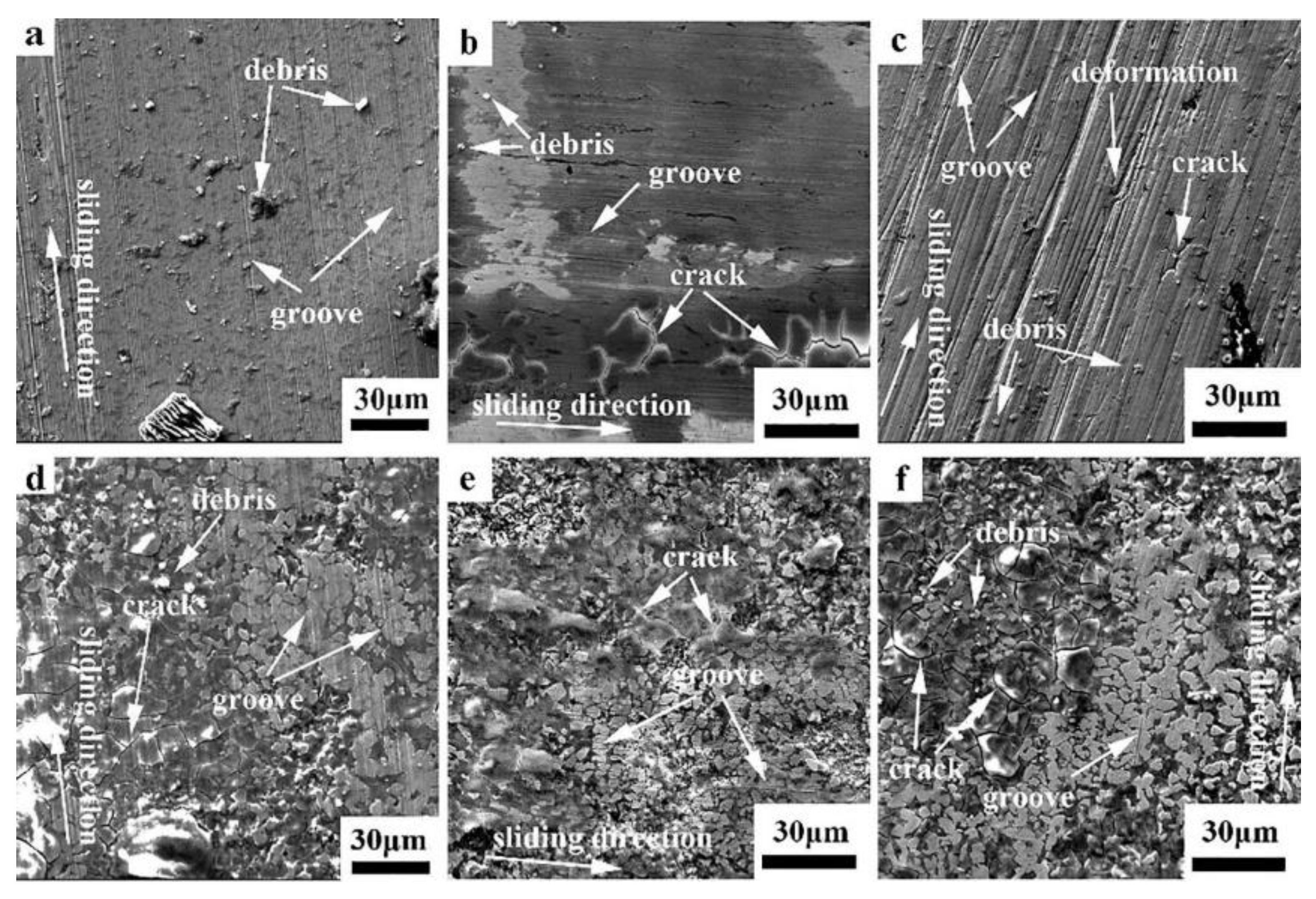
3.3.3. Worn Surface and Wear Mechanism
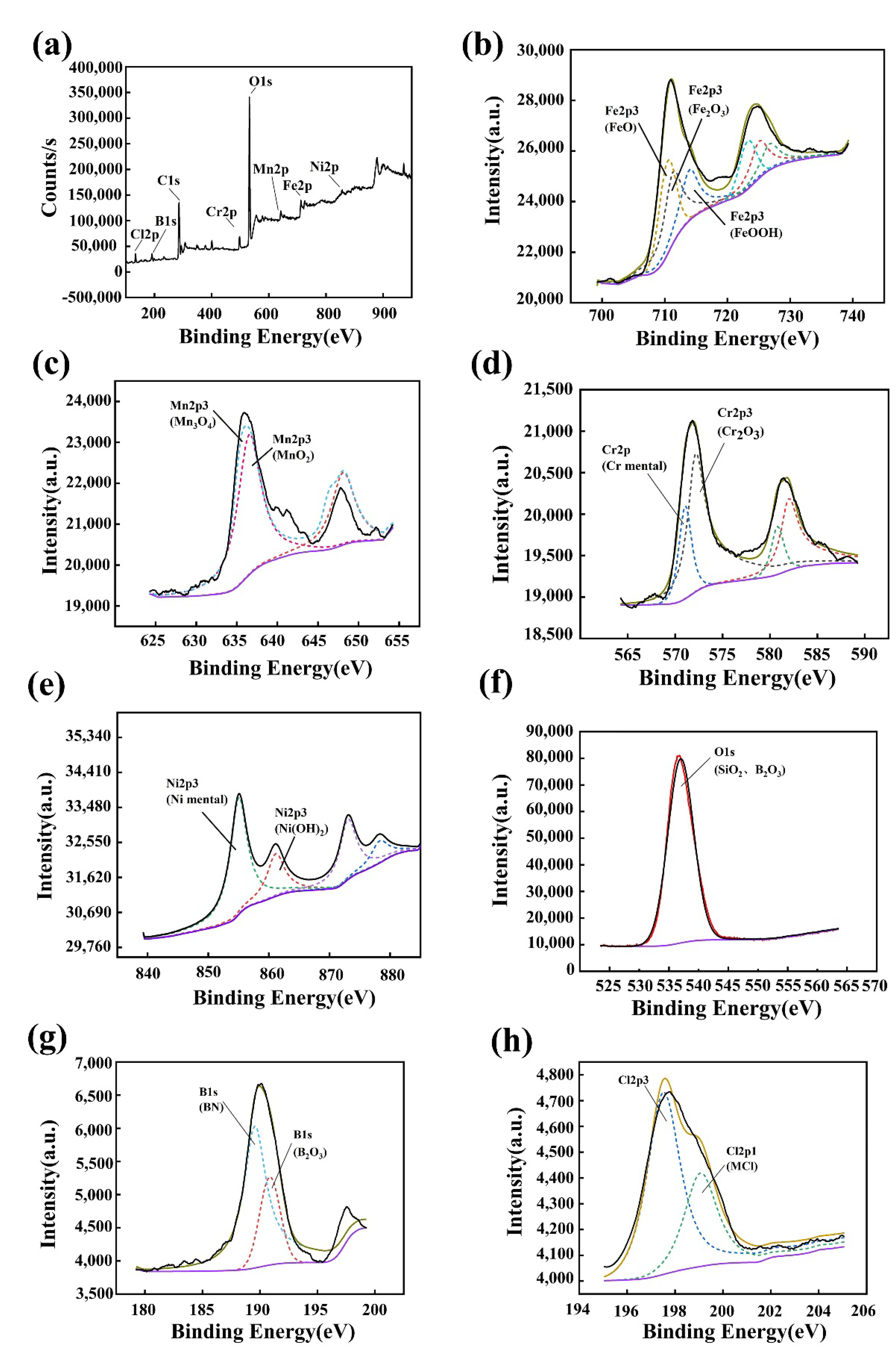
3.4. XPS Examination
4. Conclusions
Author Contributions
Funding
Institutional Review Board Statement
Informed Consent Statement
Data Availability Statement
Conflicts of Interest
References
- Yeh, J.-W.; Chen, S.-K.; Lin, S.-J.; Gan, J.-Y.; Chin, T.-S.; Shun, T.-T.; Tsau, C.-H.; Chang, S.-Y. Nanostructured high-entropy alloys with multiple principal elements: Novel alloy design concepts and outcomes. Adv. Eng. Mater. 2004, 6, 299–303. [Google Scholar] [CrossRef]
- Miracle, D.; Senkov, O. A critical review of high entropy alloys and related concepts. Acta Mater. 2017, 122, 448–511. [Google Scholar] [CrossRef] [Green Version]
- He, J.; Liu, W.; Wang, H.; Wu, Y.; Liu, X.; Nieh, T.; Lu, Z. Effects of Al addition on structural evolution and tensile properties of the FeCoNiCrMn high-entropy alloy system. Acta Mater. 2014, 62, 105–113. [Google Scholar] [CrossRef]
- Stepanov, N.; Yurchenko, N.; Skibin, D.; Tikhonovsky, M.; Salishchev, G. Structure and mechanical properties of the AlCrxNbTiV (x = 0, 0.5, 1, 1.5) high entropy alloys. J. Alloys Compd. 2015, 652, 266–280. [Google Scholar] [CrossRef]
- Tsai, M.-H.; Yeh, J.-W. High-entropy alloys: A critical review. Mater. Res. Lett. 2014, 2, 107–123. [Google Scholar] [CrossRef]
- Yang, X.; Zhang, Y. Prediction of high-entropy stabilized solid-solution in multi-component alloys. Mater. Chem. Phys. 2012, 132, 233–238. [Google Scholar] [CrossRef]
- Zhang, Y.; Yang, X.; Liaw, P.K. Alloy design and properties optimization of high-entropy alloys. JOM 2012, 64, 830–838. [Google Scholar] [CrossRef]
- Zhang, K.; Fu, Z.; Zhang, J.; Wang, W.; Wang, H.; Wang, Y.; Zhang, Q.; Shi, J. Microstructure and mechanical properties of CoCrFeNiTiAlx high-entropy alloys. Mater. Sci. Eng. A 2009, 508, 214–219. [Google Scholar] [CrossRef]
- Ma, S.; Zhang, Y. Effect of Nb addition on the microstructure and properties of AlCoCrFeNi high-entropy alloy. Mater. Sci. Eng. A 2012, 532, 480–486. [Google Scholar] [CrossRef]
- Otto, F.; Dlouhý, A.; Somsen, C.; Bei, H.; Eggeler, G.; George, E. The influences of temperature and microstructure on the tensile properties of a CoCrFeMnNi high-entropy alloy. Acta Mater. 2013, 61, 5743–5755. [Google Scholar] [CrossRef] [Green Version]
- Tong, C.-J.; Chen, M.-R.; Yeh, J.-W.; Lin, S.-J.; Chen, S.-K.; Shun, T.-T.; Chang, S.-Y. Mechanical performance of the AlxCoCrCuFeNi high-entropy alloy system with multiprincipal elements. Metall. Mater. Trans. A 2005, 36, 1263–1271. [Google Scholar] [CrossRef]
- Chuang, M.-H.; Tsai, M.-H.; Wang, W.-R.; Lin, S.-J.; Yeh, J.-W. Microstructure and wear behavior of AlxCo1.5CrFeNi1.5Tiy high-entropy alloys. Acta Mater. 2011, 59, 6308–6317. [Google Scholar] [CrossRef]
- Qiu, X.-W.; Zhang, Y.-P.; He, L.; Liu, C.-G. Microstructure and corrosion resistance of AlCrFeCuCo high entropy alloy. J. Alloys Compd. 2013, 549, 195–199. [Google Scholar] [CrossRef]
- Zhou, Y.J.; Zhang, A.; Wang, Y.L.; Chen, G.L. Solid solution alloys of AlCoCrFeNiTix with excellent room-temperature mechanical properties. Appl. Phys. Lett. 2007, 90, 181904. [Google Scholar] [CrossRef]
- Lin, C.-M.; Tsai, H.-L. Evolution of microstructure, hardness, and corrosion properties of high-entropy Al0.5CoCrFeNi alloy. Intermetallics 2011, 19, 288–294. [Google Scholar] [CrossRef]
- Stott, F.H. The role of oxidation in the wear of alloys. Tribol. Int. 1998, 31, 61–71. [Google Scholar] [CrossRef]
- Katsamas, A.; Haidemenopoulos, G. Laser-beam carburizing of low-alloy steels. Surf. Coat. Technol. 2001, 139, 183–191. [Google Scholar] [CrossRef]
- Tang, W.-Y.; Yeh, J.-W. Effect of aluminum content on plasma-nitrided Alx CoCrCuFeNi high-entropy alloys. Met. Mater. Trans. A 2009, 40, 1479–1486. [Google Scholar] [CrossRef]
- Béjar, M.; Moreno, E. Abrasive wear resistance of boronized carbon and low-alloy steels. J. Mater. Process. Technol. 2006, 173, 352–358. [Google Scholar] [CrossRef]
- Samy, B.; Narayanan, T.S.; Ravichandran, K.S.; Park, I.S.; Lee, M.H. Pack boronizing of AISI H11 tool steel: Role of surface mechanical attrition treatment. Vacuum 2013, 97, 36–43. [Google Scholar] [CrossRef]
- Kaczmarek, M.; Jurczyk, M.; Miklaszewski, A.; Paszel-Jaworska, A.; Romaniuk-Drapała, A.; Lipińska, N.; Żurawski, J.; Urbaniak, P.; Jurczyk, K. In vitro biocompatibility of titanium after plasma surface alloying with boron. Mater. Sci. Eng. C 2016, 69, 1240–1247. [Google Scholar] [CrossRef] [PubMed]
- Tabur, M.; Izciler, M.; Gul, F.; Karacan, I. Abrasive wear behavior of boronized AISI 8620 steel. Wear 2009, 266, 1106–1112. [Google Scholar] [CrossRef]
- Hou, J.; Zhang, M.; Yang, H.; Qiao, J.; Wu, Y. Surface strengthening in Al0.25CoCrFeNi high-entropy alloy by boronizing. Mater. Lett. 2019, 238, 258–260. [Google Scholar] [CrossRef]
- Wu, Y.; Yang, H.; Guo, R.; Wang, X.; Shi, X.; Liaw, P.; Qiao, J. Tribological behavior of boronized Al0.1CoCrFeNi high-entropy alloys under dry and lubricated conditions. Wear 2020, 460–461, 203452. [Google Scholar] [CrossRef]
- Bian, B.; Guo, N.; Yang, H.; Guo, R.; Yang, L.; Wu, Y.; Qiao, J. A novel cobalt-free FeMnCrNi medium-entropy alloy with exceptional yield strength and ductility at cryogenic temperature. J. Alloys Compd. 2020, 827, 153981. [Google Scholar] [CrossRef]
- Nutor, R.K.; Azeemullah, M.; Cao, Q.P.; Wang, X.D.; Zhang, D.X.; Jiang, J.Z. Microstructure and properties of a Co-freeFe50Mn27Ni10Cr13 high entropy alloy. J. Alloys Compd. 2021, 851, 156842. [Google Scholar] [CrossRef]
- Meric, C.; Sahin, S.; Backir, B.; Koksal, N. Investigation of the boronizing effect on the abrasive wear behavior in cast irons. Mater. Des. 2006, 27, 751–757. [Google Scholar] [CrossRef]
- Martini, C.; Palombarini, G.; Carbucicchio, M. Mechanism of thermochemical growth of iron borides on iron. J. Mater. Sci. 2004, 39, 933–937. [Google Scholar] [CrossRef]
- D’Souza, B.; Leong, A.; Yang, Q.; Zhang, J. Corrosion behavior of boronized nickel-based alloys in the molten chloride salt. Corros. Sci. 2021, 182, 109285. [Google Scholar] [CrossRef]
- Zhang, H.; Zhong, X.C.; He, Y.Z.; Li, W.H.; Wu, W.F.; Chen, G.; Guo, S. Effect of high configuration entropy and rare earth addition on boride precipitation and mechanical properties of multi-principal-element alloys. J. Mater. Eng. Perform. 2017, 26, 3750–3755. [Google Scholar] [CrossRef]
- Zhang, H.; He, Y.; Pan, Y. Enhanced hardness and fracture toughness of the laser-solidified FeCoNiCrCuTiMoAlSiB0.5 high-entropy alloy by martensite strengthening. Scr. Mater. 2013, 69, 342–345. [Google Scholar] [CrossRef]
- Khruschov, M. Principles of abrasive wear. Wear 1974, 28, 69–88. [Google Scholar] [CrossRef]
- Wang, X.; Li, D. Investigation of the synergism of wear and corrosion using an electrochemical scratch technique. Tribol. Lett. 2001, 11, 117–120. [Google Scholar] [CrossRef]
- Wu, J.-M.; Lin, S.-J.; Yeh, J.-W.; Chen, S.-K.; Huang, Y.-S.; Chen, H.-C. Adhesive wear behavior of AlxCoCrCuFeNi high-entropy alloys as a function of aluminum content. Wear 2006, 261, 513–519. [Google Scholar] [CrossRef] [Green Version]
- Erdemir, A.; Bindal, C.; Fenske, G.R. Formation of ultralow friction surface films on boron carbide. Appl. Phys. Lett. 1996, 68, 1637–1639. [Google Scholar] [CrossRef]
- Bindal, C.; Erdemir, A. Ultralow friction behavior of borided steel surfaces after flash annealing. Appl. Phys. Lett. 1996, 68, 923–925. [Google Scholar] [CrossRef]
- Lin, X.; Bai, Z.; Liu, Y.; Tang, B.; Yang, H. Sliding tribological characteristics of in-situ dendrite-reinforced Zr-based metallic glass matrix composites in the acid rain. J. Alloys Compd. 2016, 686, 866–873. [Google Scholar] [CrossRef]
- Xu, J.; Kato, K. Formation of tribochemical layer of ceramics sliding in water and its role for low friction. Wear 2000, 245, 61–75. [Google Scholar] [CrossRef]
- Duan, H.; Wu, Y.; Hua, M.; Yuan, C.; Wang, D.; Tu, J.; Kou, H.; Li, J. Tribological properties of AlCoCrFeNiCu high-entropy alloy in hydrogen peroxide solution and in oil lubricant. Wear 2012, 297, 1045–1051. [Google Scholar] [CrossRef]


| Average Wear Rate (×10−4 mm3/Nm) | Air | Deionized Water | Seawater | ||||||
|---|---|---|---|---|---|---|---|---|---|
| 5 N | 10 N | 15 N | 5 N | 10 N | 15 N | 5 N | 10 N | 15 N | |
| Hot rolled | 0.56 | 2.99 | 4.51 | 4.73 | 5.99 | 2.4 | 1.04 | 7.47 | 7.85 |
| Boronized | 0.45 | 1.71 | 0.72 | 0.46 | 1.63 | 0.84 | 0.93 | 1.04 | 0.75 |
| Average Friction Coefficient | Air | Deionized Water | Seawater | ||||||
|---|---|---|---|---|---|---|---|---|---|
| 5 N | 10 N | 15 N | 5 N | 10 N | 15 N | 5 N | 10 N | 15 N | |
| Hot rolled | 0.50 | 0.20 | 0.38 | 0.31 | 0.37 | 0.18 | 0.38 | 0.61 | 0.55 |
| Boronized | 0.24 | 0.21 | 0.30 | 0.08 | 0.33 | 0.17 | 0.18 | 0.44 | 0.45 |
| Sample State | Fe | Mn | Cr | Ni | B | O | Si |
|---|---|---|---|---|---|---|---|
| Hot rolled; 5 N | |||||||
| Surface | 16.7 ± 0.1 | 3.4 ± 0.1 | 6.1 ± 0.1 | 10.8 ± 0.1 | - | 63.0 ± 0.1 | - |
| Debris | 25.1 ± 0.1 | 10.4 ± 0.1 | 11.8 ± 0.1 | 10.9 ± 0.1 | - | 41.8 ± 0.1 | - |
| Hot rolled; 10 N | |||||||
| Surface | 28.8 ± 0.1 | 11.8 ± 0.1 | 13.7 ± 0.1 | 13.1 ± 0.1 | - | 32.6 ± 0.1 | - |
| Debris | 26.1 ± 0.1 | 9.8 ± 0.1 | 11.4 ± 0.1 | 11.8 ± 0.1 | - | 39.8 ± 0.1 | 1.1 ± 0.1 |
| Hot rolled; 15 N | |||||||
| Surface | 24.4 ± 0.1 | 11.8 ± 0.1 | 15.7 ± 0.1 | 11.9 ± 0.1 | - | 36.2 ± 0.1 | - |
| Debris | 18.9 ± 0.1 | 7.9 ± 0.1 | 8.8 ± 0.1 | 7.6 ± 0.1 | - | 54.3 ± 0.1 | 2.5 ± 0.1 |
| Boronized; 5 N | |||||||
| Surface | 29.1 ± 0.1 | 10.0 ± 0.1 | 18.9 ± 0.1 | 7.5 ± 0.1 | 14.3 ± 0.1 | 20.2 ± 0.1 | - |
| Debris | 25.2 ± 0.1 | 8.3 ± 0.1 | 13.8 ± 0.1 | 4.1 ± 0.1 | 1.7 ± 0.1 | 45.2 ± 0.1 | 1.7 ± 0.1 |
| Boronized; 10 N | |||||||
| Surface | 22.4 ± 0.1 | 11.6 ± 0.1 | 14.2 ± 0.1 | 12.2 ± 0.1 | 17.1 ± 0.1 | 20.5 ± 0.1 | 2.0 ± 0.1 |
| Debris | 18.4 ± 0.1 | 6.5 ± 0.1 | 7.5 ± 0.1 | 7.3 ± 0.1 | 3.5 ± 0.1 | 50.9 ± 0.1 | 5.9 ± 0.1 |
| Boronized; 15 N | |||||||
| Surface | 29.7 ± 0.1 | 13.2 ± 0.1 | 15.2 ± 0.1 | 13.6 ± 0.1 | 14.9 ± 0.1 | 10.2 ± 0.1 | 3.2 ± 0.1 |
| Debris | 20.7 ± 0.1 | 8.9 ± 0.1 | 9.2 ± 0.1 | 8.7 ± 0.1 | 5.3 ± 0.1 | 44.6 ± 0.1 | 2.6 ± 0.1 |
| Sample State | Fe | Mn | Cr | Ni | B | O | Si |
|---|---|---|---|---|---|---|---|
| Hot Rolled; 5 N | |||||||
| Surface | 33.4 ± 0.1 | 13.4 ± 0.1 | 15.7 ± 0.1 | 14.5 ± 0.1 | - | 23.0 ± 0.1 | - |
| Debris | 22.6 ± 0.1 | 12.1 ± 0.1 | 10.3 ± 0.1 | 14.4 ± 0.1 | - | 25.9 ± 0.1 | 14.7 ± 0.1 |
| Hot rolled; 10 N | |||||||
| Surface | 26.6 ± 0.1 | 10.7 ± 0.1 | 12.5 ± 0.1 | 11.9 ± 0.1 | - | 35.9 ± 0.1 | 2.4 ± 0.1 |
| Debris | 25.1 ± 0.1 | 9.9 ± 0.1 | 11.7 ± 0.1 | 11.2 ± 0.1 | - | 39.3 ± 0.1 | 2.8 ± 0.1 |
| Hot rolled; 15 N | |||||||
| Surface | 32.7 ± 0.1 | 13.4 ± 0.1 | 15.7 ± 0.1 | 15.1 ± 0.1 | - | 23.1 ± 0.1 | - |
| Debris | 38.7 ± 0.1 | 15.9 ± 0.1 | 18.5 ± 0.1 | 17.8 ± 0.1 | - | 9.1 ± 0.1 | - |
| Boronized; 5 N | |||||||
| Surface | 13.3 ± 0.1 | 5.1 ± 0.1 | 0.4 ± 0.1 | 17.0 ± 0.1 | 11.7 ± 0.1 | 35.4 ± 0.1 | 17.1 ± 0.1 |
| Debris | 11.7 ± 0.1 | 6.2 ± 0.1 | 8.2 ± 0.1 | 53.1 ± 0.1 | 3.5 ± 0.1 | 15.6 ± 0.1 | 1.7 ± 0.1 |
| Boronized; 10 N | |||||||
| Surface | 16.5 ± 0.1 | 8.3 ± 0.1 | 5.7 ± 0.1 | 7.5 ± 0.1 | 15.2 ± 0.1 | 31.4 ± 0.1 | 15.4 ± 0.1 |
| Debris | 5.6 ± 0.1 | 5.7 ± 0.1 | 7.6 ± 0.1 | 4.8 ± 0.1 | 5.6 ± 0.1 | 68.2 ± 0.1 | 2.5 ± 0.1 |
| Boronized; 15 N | |||||||
| Surface | 13.1 ± 0.1 | 2.7 ± 0.1 | 5.4 ± 0.1 | 16.2 ± 0.1 | 12.2 ± 0.1 | 50.4 ± 0.1 | - |
| Debris | 4.4 ± 0.1 | 3.9 ± 0.1 | 0.4 ± 0.1 | 66.4 ± 0.1 | 4.4 ± 0.1 | 20.5 ± 0.1 | - |
| Sample State | Fe | Mn | Cr | Ni | B | O | Na | Cl |
|---|---|---|---|---|---|---|---|---|
| Hot rolled; 5 N | ||||||||
| Surface | 19.3 ± 0.1 | 7.2 ± 0.1 | 9.9 ± 0.1 | 8.8 ± 0.1 | - | 42.4 ± 0.1 | 8.7 ± 0.1 | 3.7 ± 0.1 |
| Debris | 4.2 ± 0.1 | 1.1 ± 0.1 | 1.8 ± 0.1 | 1.0 ± 0.1 | - | 15.4 ± 0.1 | 54.8 ± 0.1 | 21.7 ± 0.1 |
| Hot rolled; 10 N | ||||||||
| Surface | 29.4 ± 0.1 | 14.9 ± 0.1 | 13.3 ± 0.1 | 13.6 ± 0.1 | - | 28.8 ± 0.1 | - | - |
| Debris | 9.0 ± 0.1 | 2.8 ± 0.1 | 3.7 ± 0.1 | 2.9 ± 0.1 | - | 2.4 ± 0.1 | 60.2 ± 0.1 | 19.0 ± 0.1 |
| Hot rolled; 15 N | ||||||||
| Surface | 32.1 ± 0.1 | 13.0 ± 0.1 | 15.2 ± 0.1 | 14.7 ± 0.1 | - | 24.9 ± 0.1 | - | 0.1 ± 0.1 |
| Debris | 26.9 ± 0.1 | 9.7 ± 0.1 | 13.9 ± 0.1 | 12.2 ± 0.1 | - | 35.2 ± 0.1 | 0.4 ± 0.1 | 1.7 ± 0.1 |
| Boronized; 5 N | ||||||||
| Surface | 10.2 ± 0.1 | 6.5 ± 0.1 | 4.6 ± 0.1 | 12.4 ± 0.1 | 6.4 ± 0.1 | 26.9 ± 0.1 | 20.3 ± 0.1 | 12.7 ± 0.1 |
| Debris | 7.3 ± 0.1 | 7.5 ± 0.1 | 4.5 ± 0.1 | 17.6 ± 0.1 | 8.4 ± 0.1 | 40.2 ± 0.1 | 12.6 ± 0.1 | 1.8 ± 0.1 |
| Boronized; 10 N | ||||||||
| Surface | 13.6 ± 0.1 | 1.1 ± 0.1 | 1.5 ± 0.1 | 10.6 ± 0.1 | 19.4 ± 0.1 | 24.2 ± 0.1 | 24.2 ± 0.1 | 5.4 ± 0.1 |
| Debris | 9.8 ± 0.1 | 1.6 ± 0.1 | 1.5 ± 0.1 | 7.8 ± 0.1 | 18.5 ± 0.1 | 28.4 ± 0.1 | 28.3 ± 0.1 | 4.1 ± 0.1 |
| Boronized; 15 N | ||||||||
| Surface | 7.3 ± 0.1 | 5.4 ± 0.1 | 0.3 ± 0.1 | 74.2 ± 0.1 | 4.4 ± 0.1 | 4.3 ± 0.1 | 2.6 ± 0.1 | 0.9 ± 0.1 |
| Debris | 4.5 ± 0.1 | 40.5 ± 0.1 | 0.7 ± 0.1 | 13.0 ± 0.1 | 5.2 ± 0.1 | 36.1 ± 0.1 | - | - |
Publisher’s Note: MDPI stays neutral with regard to jurisdictional claims in published maps and institutional affiliations. |
© 2021 by the authors. Licensee MDPI, Basel, Switzerland. This article is an open access article distributed under the terms and conditions of the Creative Commons Attribution (CC BY) license (https://creativecommons.org/licenses/by/4.0/).
Share and Cite
Guo, X.; Jin, X.; Shi, X.; Yang, H.; Zhang, M.; Qiao, J. Tribological Behavior of Boronized Fe40Mn20Cr20Ni20 High-Entropy Alloys. Metals 2021, 11, 1561. https://doi.org/10.3390/met11101561
Guo X, Jin X, Shi X, Yang H, Zhang M, Qiao J. Tribological Behavior of Boronized Fe40Mn20Cr20Ni20 High-Entropy Alloys. Metals. 2021; 11(10):1561. https://doi.org/10.3390/met11101561
Chicago/Turabian StyleGuo, Xin, Xi Jin, Xiaohui Shi, Huijun Yang, Min Zhang, and Junwei Qiao. 2021. "Tribological Behavior of Boronized Fe40Mn20Cr20Ni20 High-Entropy Alloys" Metals 11, no. 10: 1561. https://doi.org/10.3390/met11101561
APA StyleGuo, X., Jin, X., Shi, X., Yang, H., Zhang, M., & Qiao, J. (2021). Tribological Behavior of Boronized Fe40Mn20Cr20Ni20 High-Entropy Alloys. Metals, 11(10), 1561. https://doi.org/10.3390/met11101561