Article

Using a Trial Sample on Stainless Steel 316L in a Direct Laser Deposition Process

1
Institute of Metallurgy, Mechanical Engineering and Transport, Peter the Great St. Petersburg Polytechnic University, 195251 St. Petersburg, Russia
2
Institute of Laser and Welding Technology, St. Petersburg State Marine Technical University, 190121 St. Petersburg, Russia
*
Author to whom correspondence should be addressed.
Metals 2021, 11(10), 1550; https://doi.org/10.3390/met11101550
Submission received: 7 August 2021 / Revised: 9 September 2021 / Accepted: 21 September 2021 / Published: 28 September 2021
(This article belongs to the Special Issue Laser Processing of Metals and Alloys)

Abstract

:
Direct laser deposition technology is used for the manufacture of large-size products with complex geometries. As a rule, trial samples with small dimensions are made to determine the deposition parameters. In order for the resulting products to have the required performance characteristics, it is necessary to minimize the number of internal macrodefects. Non-fusion between the tracks are defects that depend on the technological mode (power, speed, track width, etc.). In this work, studies have been carried out to determine the power level at which non-fusion is formed, dwell time between the tracks on the model samples. This paper considers the issue of transferring the technological parameters of direct laser deposition from model samples to a large-sized part, and describes the procedure for making model samples.

1. Introduction

With the introduction of direct laser deposition technology in various industries, the requirements for manufactured products are growing [1,2,3]. Additive manufacturing technologies are currently being widely developed in all industrialized countries [4]. Such technologies allow, in some cases, significantly lower energy and material costs compared to traditional manufacturing processes. The most promising technology for the manufacture of large-sized metal products is direct laser deposition (DLD) or, as it is also called, direct energy deposition using laser beam (DED-LB). The method is based on the formation of geometry by three-dimensional deposition of a metal powder with a laser beam [5,6].
One of the commonly used materials is 316L stainless steel [7,8,9,10]. The material is widely used and studied due to the combination of relatively high mechanical properties and corrosion resistance [11,12,13,14]. Today, many parts are manufactured from 316L steel by additive methods, such as: parts for the shipbuilding industry (different impellers and propellers), aircraft and aerospace industries (different sections).
Some large parts have a continuous deposition time of more than 100 h, therefore the product parts must meet all specifications. One of the main stages of preparation is to determine the technological parameters of the surfacing process, namely: laser power, process speed, track width, etc. [15,16].
Since the products can have different sizes and geometries, a very important point is the portability of the technological regime to the part, obtained during the manufacture of technological samples of the products. In order for the finished samples to carry useful information, it is necessary to understand that the thermal histories of a large-sized product and a technological sample of small dimensions will be completely different. To do this, it is necessary to use the same pause between passes to repeat the thermal cycle. The deposition of preliminary samples in a continuous mode without pauses between lanes leads to severe overheating due to their small size. At the same time, similar parameters for the deposition of a large-sized product can cause lack of fusion between tracks, since the penetration depth will be insufficient due to intensive cooling of the previous layers [17,18].
In this work, 316L stainless steel samples were obtained by a direct laser deposition process. Particular attention was paid to track non-fusion. This defect is directly related to the technological mode of cladding, as well as to the formation of microstructure and microhardness of the obtained samples. In this work, model samples were examined in order to develop technological modes. As well as metallographic examination, determining wall formation and the presence of internal macrodefects were carried out. Static mechanical tensile tests were carried out. Thermal cycles of deposited samples were obtained. Analysis and causes of defects were carried out.

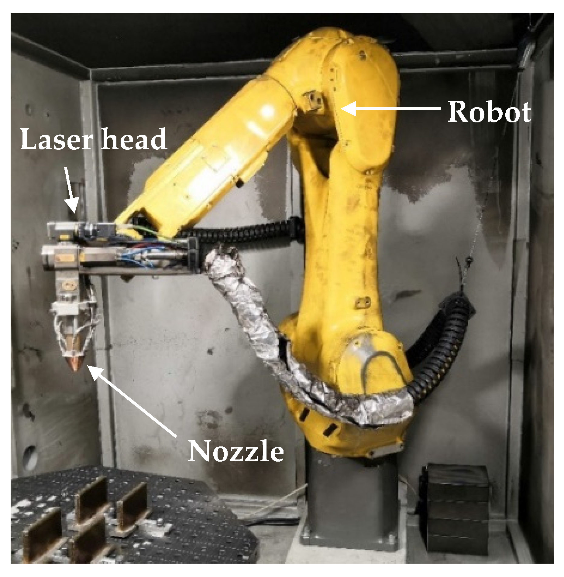
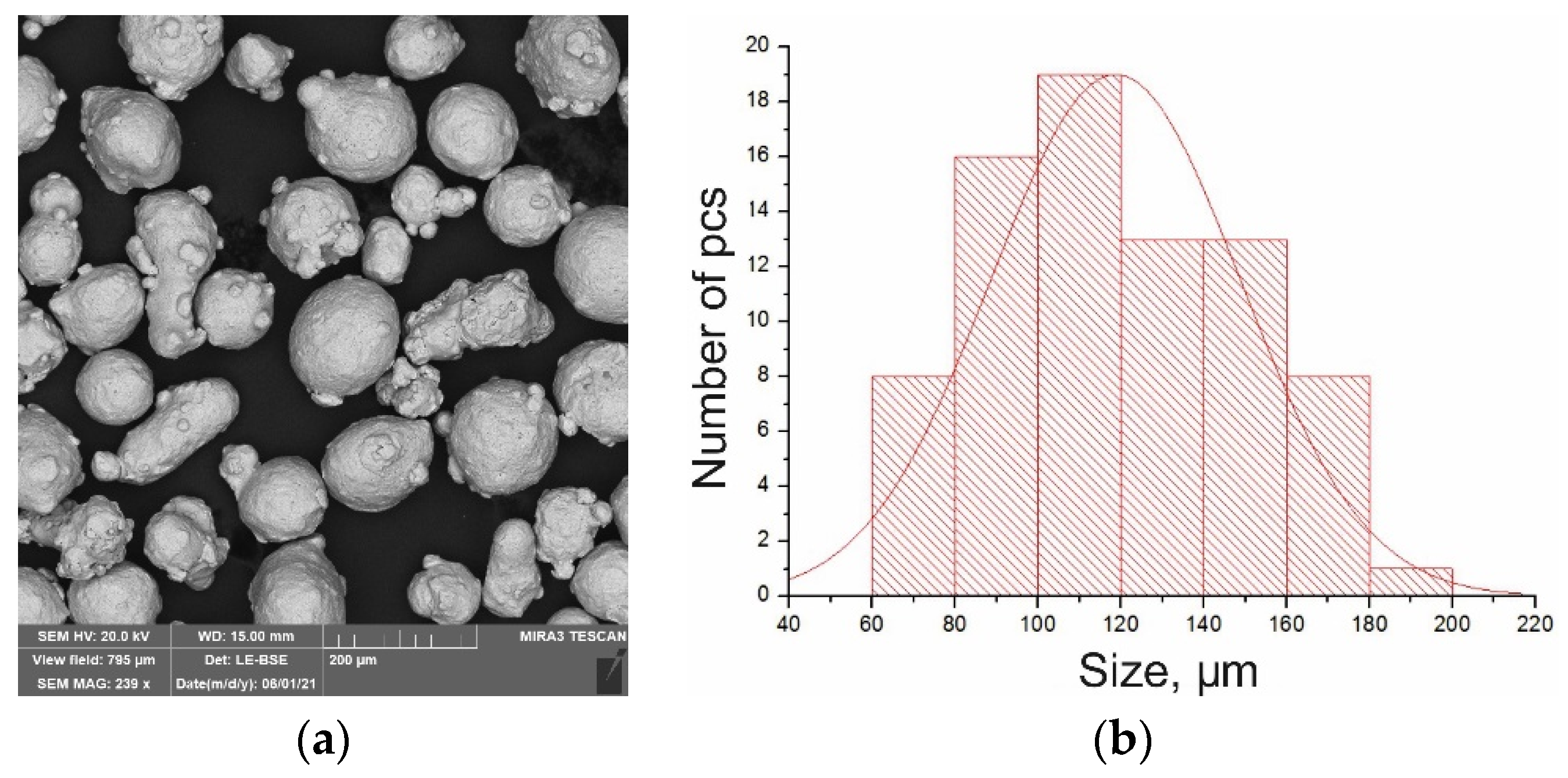
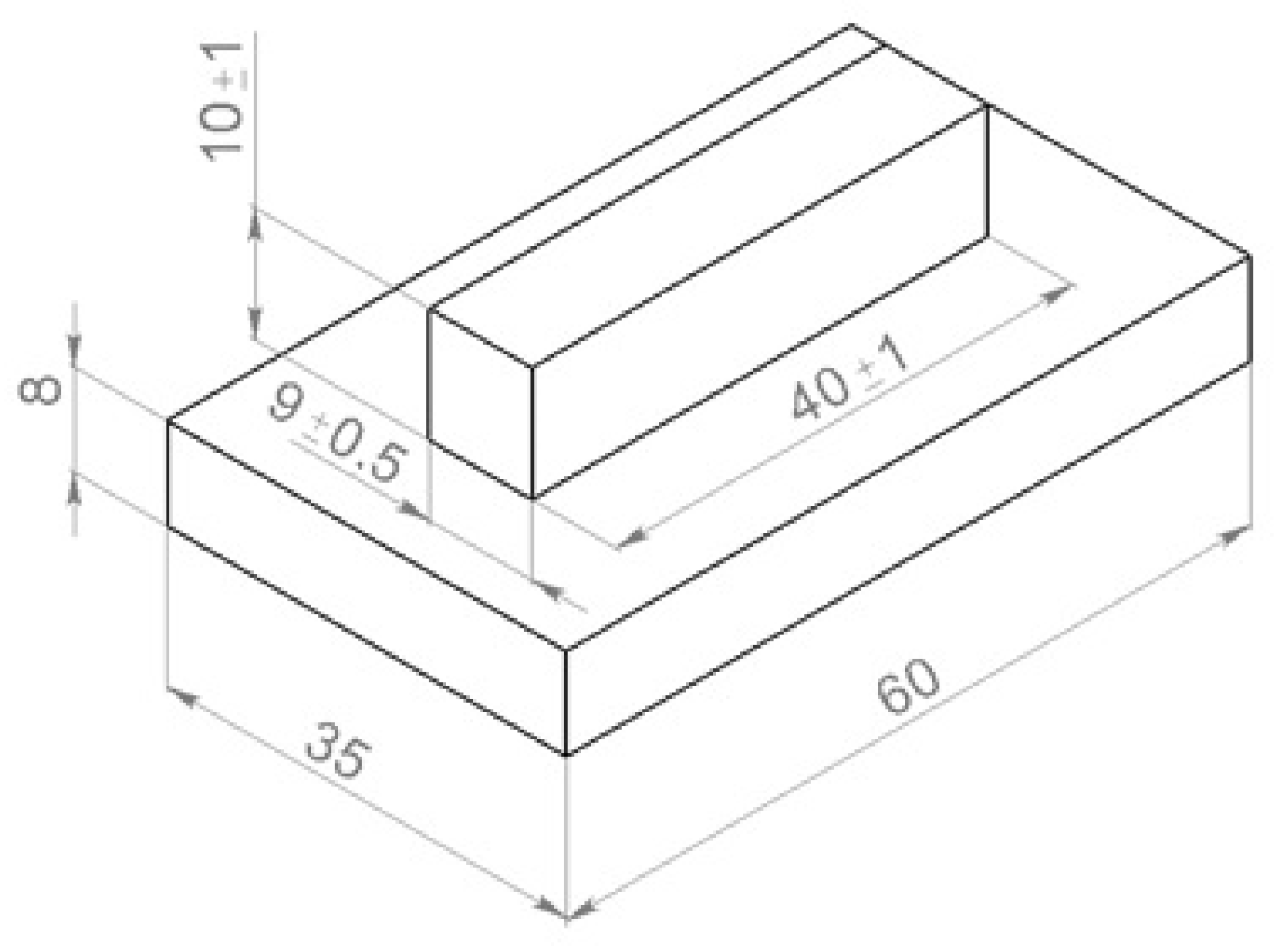
2. Materials and Methods

The samples of from austenitic stainless steel 316L were produced on a technological complex of direct laser deposition. The experiments were carried out on a robotic complex for direct laser deposition (Figure 1). Its main components were an industrial robot M20iB/25 (Fanuc, Oshino-mura, Japan), LS-3 ytterbium fiber laser (IPG Photonics, Oxford, MA, USA), and a FLW D30 laser focusing head (IPG Photonics, Oxford, MA, USA) with a four-jet nozzle.
All the samples were deposited in an argon atmosphere in the sealed box. In the experiments, metallic powder of fraction 60–200 μm from austenitic stainless steel 316L ASTM A240. Table 1 shows the chemical composition of the 316L powder:
Figure 2 shows thepowder particles and a particle histogram:
Powder was obtained by the gas atomization method. The particle size distribution was 60–200 microns, the powder surface was satisfactory, and the chemical composition was within the acceptable range according to ASTM A240. The powder particles had an elongated shape, and the sphericity of the powder was ψ = 0.89. The powder contained elliptical and irregular-shaped particles, and satellites were found on the surface. For chemical analysis of 316L powder, a scanning electron microscope Tescan Mira3 with an energy-dispersive microanalysis system Advanced Ultim Max 65 (Tescan, Brno, Czech Republic).
In this study, two series (eight samples each, Table 2) with different pauses between the adjacent tracks were made. In the first series, the dwell time was 5 min. Such a big pause between the layers imitates a very large product, the most aggressive conditions for the tracks formation, and favorable conditions for non-fusion. Deposition was carried out in single passes (not raster), Δz between layers was 0.8 mm. In the second series, the waiting time between the adjacent tracks was reduced twice for 2.5 min. The depositing strategy was in separate tracks, i.e., the first track was made on the first sample in the series, then the first track on the second sample, etc. The dimensions of the standard model sample are shown in Figure 3.
The power range of deposition samples that have been investigated previously was chosen for the study [18,19,20]. Table 2 shows the technological modes of the direct laser deposition process.
The chromel-alumel type K thermocouple with a wire diameter of 1.2 mm was used for measuring thermal cycles. The period of the temperature measurement by a thermocouple was 20 ms. The thermocouple was installed on the samples 1.3 and 2.3 during the process, since the power is often used with such parameters. Special attention was paid to the temperature to which the sample has time to cool between passes.
Microstructural studies were performed by light optical microscopy using an inverted Leica DMi8 (Leica Microsystems, Wetzlar, Germany) microscope equipped with an Axalit image analyzer (Axalit, Moscow, Russia). The macrostructure and microstructure were obtained by etching in HNO3 + HCl (1:3) with an exposure time of 30–60 s.
The obtained data were also used to determine the percentage of non-fusion in the macrosections. An image processing program was written in the Matlab software package. The loaded image of macrosection is converted into a binary (black and white) image. The developed algorithm allows you to find the coordinates of the boundaries points of the obtained contrast areas. Furthermore, the algorithm determines the boundaries that fall into the area of the macrosection, and this allows you to find the percentage of the pores and non-fusion area (in this case, mainly non-fusion) in the total area of the macrosection.
Microhardness measurements were performed on an FM-310 (Future Tech, Kawasaki, Japan) series microhardness tester with a 300 g Vickers load and a Thixomet Pro image analyzer (Thixomet, St. Petersburg, Russia). Mechanical tests were performed on a universal testing machine, Zwick Roell Z100 (Zwick Roell, Ulm, Germany), with a longitudinal strain gauge of 100 kN for tensile testing of metals, with two specimens for each direction. The impact toughness tests were performed on the Zwick Roell RKP450 (Zwick Roell, Ulm, Germany) at 20 °C. There were two samples to test for each direction.
The parts to be manufactured were cylindrical in shape and a full circle corresponding to a pause between tracks was a 5 min track. In this regard, two pauses of 5 min and 2.5 min (to reduce sample fabrication time) were analysed. One thermocouple was used in each series of experiments. We were most interested in the 2200 W samples, as they were potentially used at 25 mm/s and a height offset of ∆z = 0.8 mm.

3. Results and Discussion

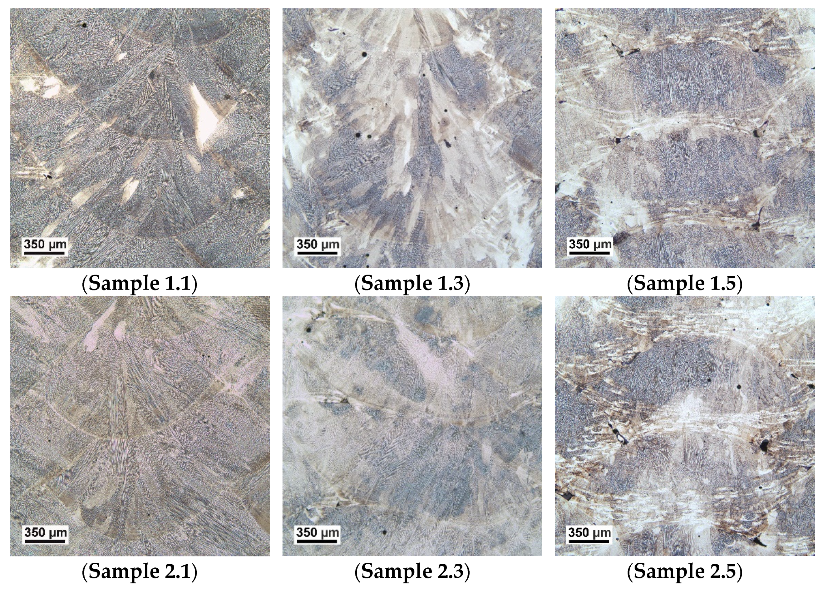
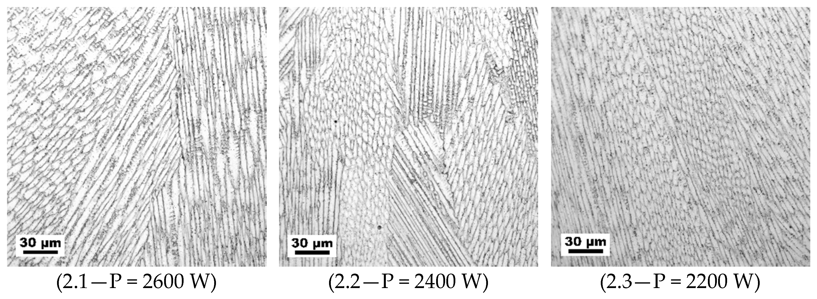
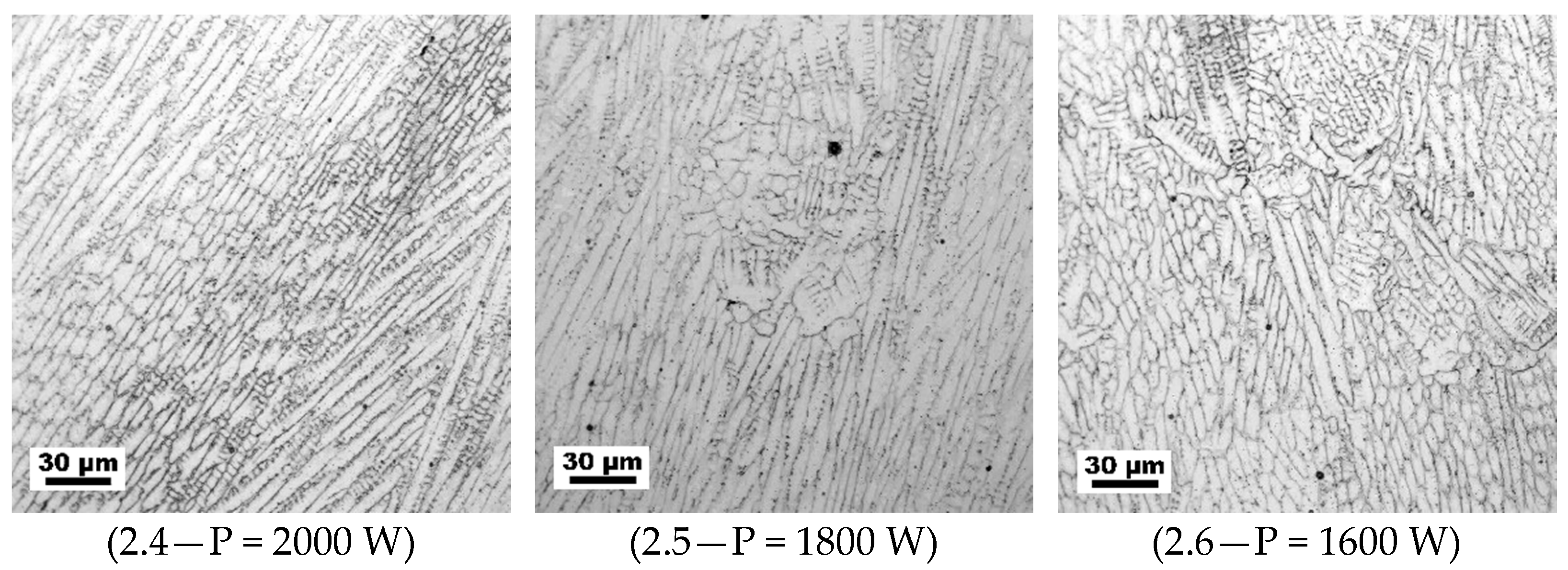
3.1. Metallographic Studies

Figure 4 and Figure 5 show samples from the experimental series for the study of defects at different laser DLD.
Figure 5 shows the macrosections of the second series samples:
Figure 5. The thin sections of the samples (second series), laser power in the range of P = 2600 W (2.1) to P = 1400 W (2.7).
Metals 11 01550 g005
Analyzing the data obtained from the microscope, we can say that the power level at which non-fusion begins to form in the first series of experiments was 2200 W, i.e., on sample 1.3 the defects were already visible. In the second series the power level dropped to 2000 W (sample 2.4). Sample 2.8 is not shown due to lack of fusion with the substrate.
Furthermore, the pore percentages were determined for each sample. Table 3 shows the data of the series No. 2:
After analysis of the macrodefects, the modes with 2600, 2200, 1800 W power were selected to determine the macrostructure and fusion zones in Figure 6.
The samples in Figure 6 (1.1, 1.3 and 2.1, 2.3) show grain growth throughout the height of the deposited material. At high power, samples 1.1 and 2.1 show a deposited track boundary through which the dendrites grow. At low power (samples 1.6 and 2.6) non-melting along the boundaries of the tracks is observed, and grains are formed inside the tracks. The grain growth is greater in sample 1.3 than in sample 2.3, which is due to the thermal cycle occurring during the deposition. The heating temperature and the average temperature of sample 2.3 are higher than those of sample 1.3 (Figure 9). The macrostructure is close to cast. At high power, the grains have blurred the boundaries of the melted tracks, indicating epitaxial growth of new grains from remelted zones following in the direction of the maximum temperature gradient.
Figure 7 investigated the microstructural features of the samples with a pause of 2.5 min.
The microstructure is a fine cellular substructure. The samples exhibit a complex cellular microstructure and small sub-grains (Figure 7), typical of samples obtained by direct laser deposition, which are the result of rapid solidification.
In the samples deposited at high power of 2600–2200 W, dendritic structure is formed, and grain growth increases with increasing power. At 2600 W the average grain size is 6.4 μm, at 2400 W 5 μm, at 2200 W 4 μm.
At further reduction of power the dependence is inverse proportional and at 2000 W—5 μm, at 1800 W—5.1 μm, at 1600 W—5.2 μm. This dependence is most probably related to partial preservation of the powder grain size when the laser does not melt the powder particles completely. Hence, the optimal laser power is 2200 W. In this case a homogeneous microstructure with fine grains will be formed, which increases the performance characteristics. Figure 8 shows the non-fusion percentage dependence on the power (for two series of samples).
The graph shows that with a power decrease, the non-fusion percentage increases, and with the decrease of the pause between the layers at the same power, the non-fusion percentage decreases. This does not apply to extremely high and low power values, at which, regardless of the pause, non-fusions are either almost absent (at high powers), or there are a lot of them (at low powers).
This method for determining the number of non-fusions is incomplete, because of the possibility of misalignment with defects while preparing samples for research. The next step of the samples study is industrial tomography, which makes it possible to obtain a real ratio of the total number of discontinuities to the entire volume of the sample.

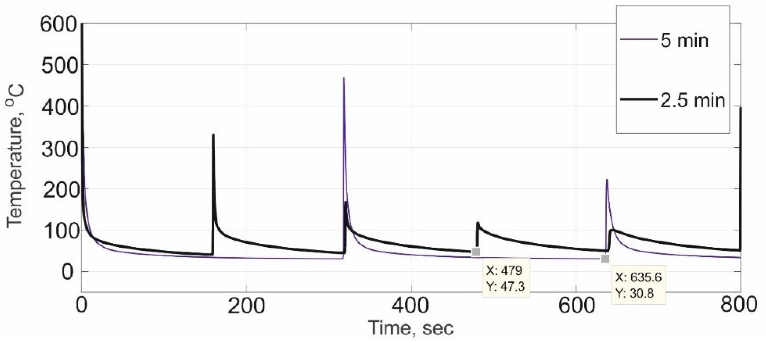
3.2. The Comparison of Thermal Cycles

As the heat source moves, an increasing volume of metal is heated, and in previously heated areas the temperature levels off. Thus, an uneven temperature field is formed in the deposition product with a large temperature gradient in the area of local heating. When making samples for analysis of microstructure and mechanical properties obtained by the DLD method, it is necessary to take into account the thermal field and thermal cycles in the deposited samples. When making samples for the analysis of microstructure and mechanical properties obtained by the DLD method, the heat input and thermal cycles in the deposited samples must be taken into account. Figure 9 shows a graph (of one layer) with two series of samples, indicating the points to which the sample was able to cool.
Figure 9 shows that the temperature of the sample’s “substrate” with a 5 min wait between the tracks is 20 degrees lower than in the sample with a 2.5 min wait, and is at the level of 30 degrees, while the power level at which non-fusion is formed in the first series is 200 watts higher.
Sample 2.3 (2.5 min) shows more significant grain growth compared to sample 1.3 (5 min), which is due to the thermal cycle occurring during precipitation. The grain size at the 2.5 min pause is 4 µm and 3.3 µm at the 5 min pause. The number of heating cycles with a pause of 2.5 min is higher compared to the pause of 5 min, and the average temperature of sample 2.3 is higher than that of sample 1.3 (Figure 9). The microstructure with the lower pause is more homogeneous and close to the cast microstructure.
Since the pause between tracks decreased from 5 min to 2.5 min and the average substrate and sample temperature increased, it is logical to assume that the penetration depth in the second series of experiments is higher than in the first. Consequently, the power level at which non-melting occurs is slightly lower in the second series of experiments than in the first. Since the difference between the experiments is small, a pause of no more than 5 min should be used to simulate the fabrication of large parts by direct laser deposition.

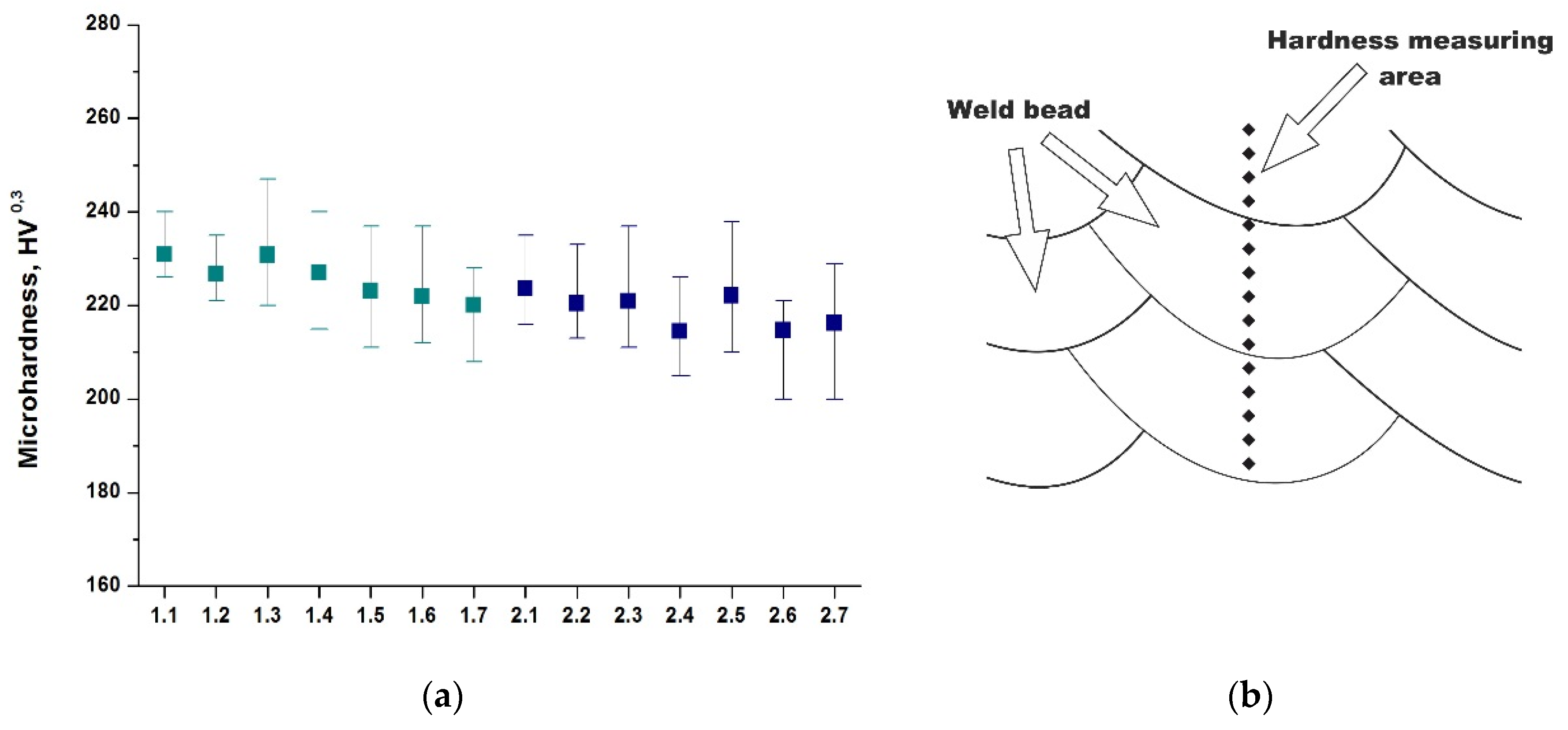
3.3. Mechanical Properties

The microhardness graph and measurement scheme of the samples are shown in Figure 10:
The micro-hardness curve (Figure 10) shows that the scatter at a pause of 5 min is greater than at a pause of 2.5 min in samples 1.1 and 1.2. In the samples of 2200 W, the scatter of values is approximately the same. It is concluded by that with increase of power of laser radiation in samples the homogeneous structure with uniform distribution of microhardness is formed. At power of 2600 and 2400 W the microhardness in samples is equally distributed. The optimal admissible power is reached in a mode with power of 2600–2400 W (mode 1.1, 1.2 and 2.1, 2.2).
The mechanical properties of the deposited samples are higher than those of the conventionally produced samples. This is due to the formation of a well-directed dendritic structure. In samples obtained by traditional casting or rolling, the 316L microstructure consists of ferrite dendrites in an austenitic matrix. The grain size is rather large, due to which the mechanical properties have high ductility and impact toughness, and the ultimate strength is significantly lower compared to the deposited material [21].
The homogeneous dendritic structure throughout the height leads to an increase in the mechanical properties of the deposited specimen. In selecting the optimal DLD modes it is necessary to take into account the fact that the choice of pause must take account for the material overheating, which can affect the deformation of the workpiece. As can be seen in Table 4, the mechanical properties are almost identical at different pauses. Consequently, reducing the sample fabrication pause from 5 min to 2.5 min speeds up the preparation process for deposition large-size parts.

4. Conclusions

In this study, two series of samples were made with different waiting time between the tracks. In this way, the thermal history of a large-sized product was simulated on small samples. We chose maximum possible working day conditions and 5 min waiting time between the layers. The second series of samples was made with a waiting time two times shorter of 2.5 min. Metallographic studies of the deposited technological samples were carried out. The percentage of discontinuities was determined within one macrosection for each sample. Thermal cycles were measured during the production of technological samples. The power levels at which non-fusions appeared between the tracks were measured.
Both temperatures of the “substrates” in the nominal mode were low. These pauses imitated very large-sized products, but only at the start of their deposition. The next step of the research will be to reduce the waiting time to 40 s. Such a waiting time is comfortable from the point of view of the time spent on making technological samples; on the other hand, the samples will be cooled enough and simulate a large-sized product. During the deposition of the next series of samples, thermal cycles will be measured and compared with the previous series. The power level of non-fusion will be determined.
Consequently, we conclude:
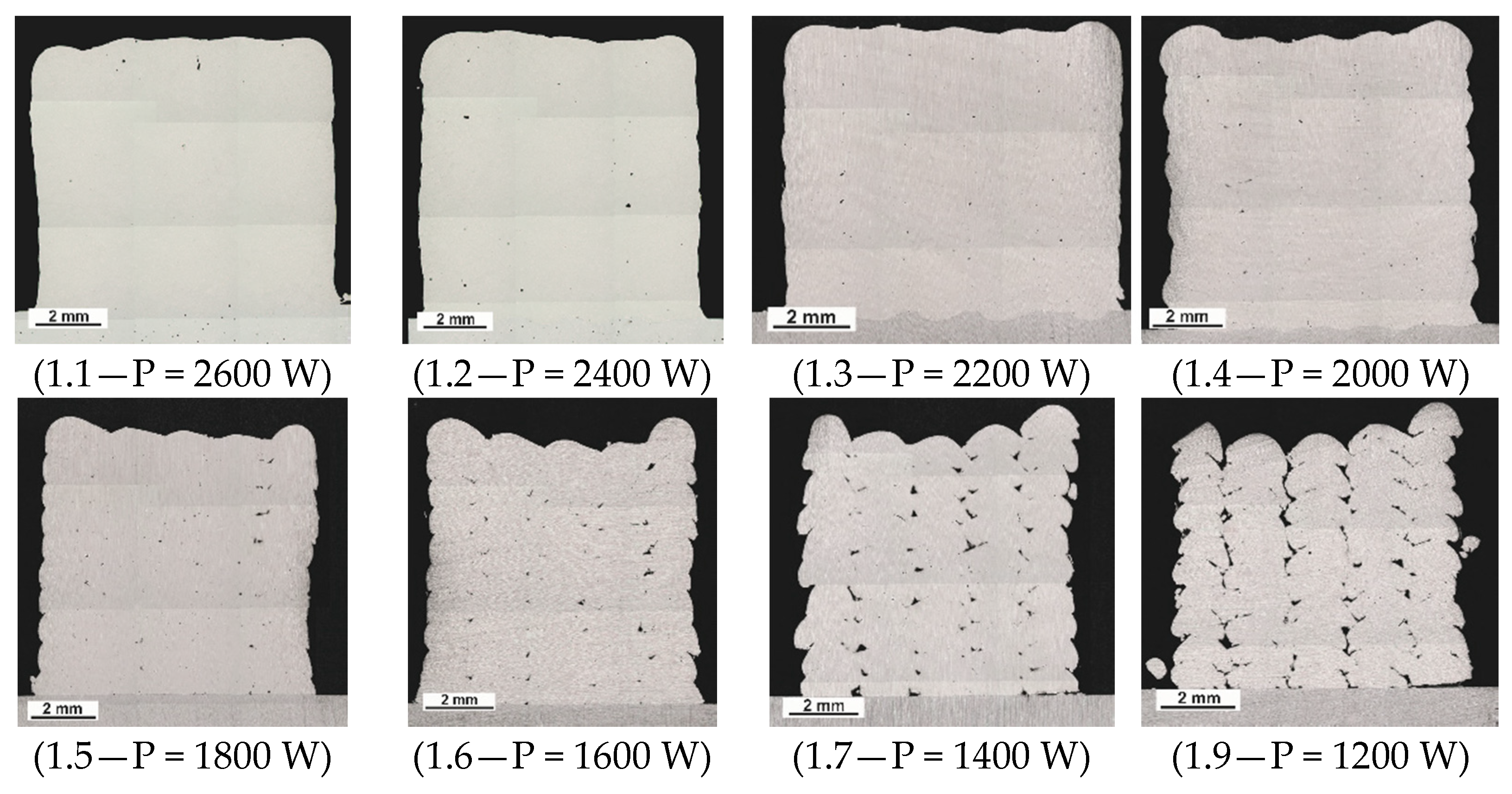
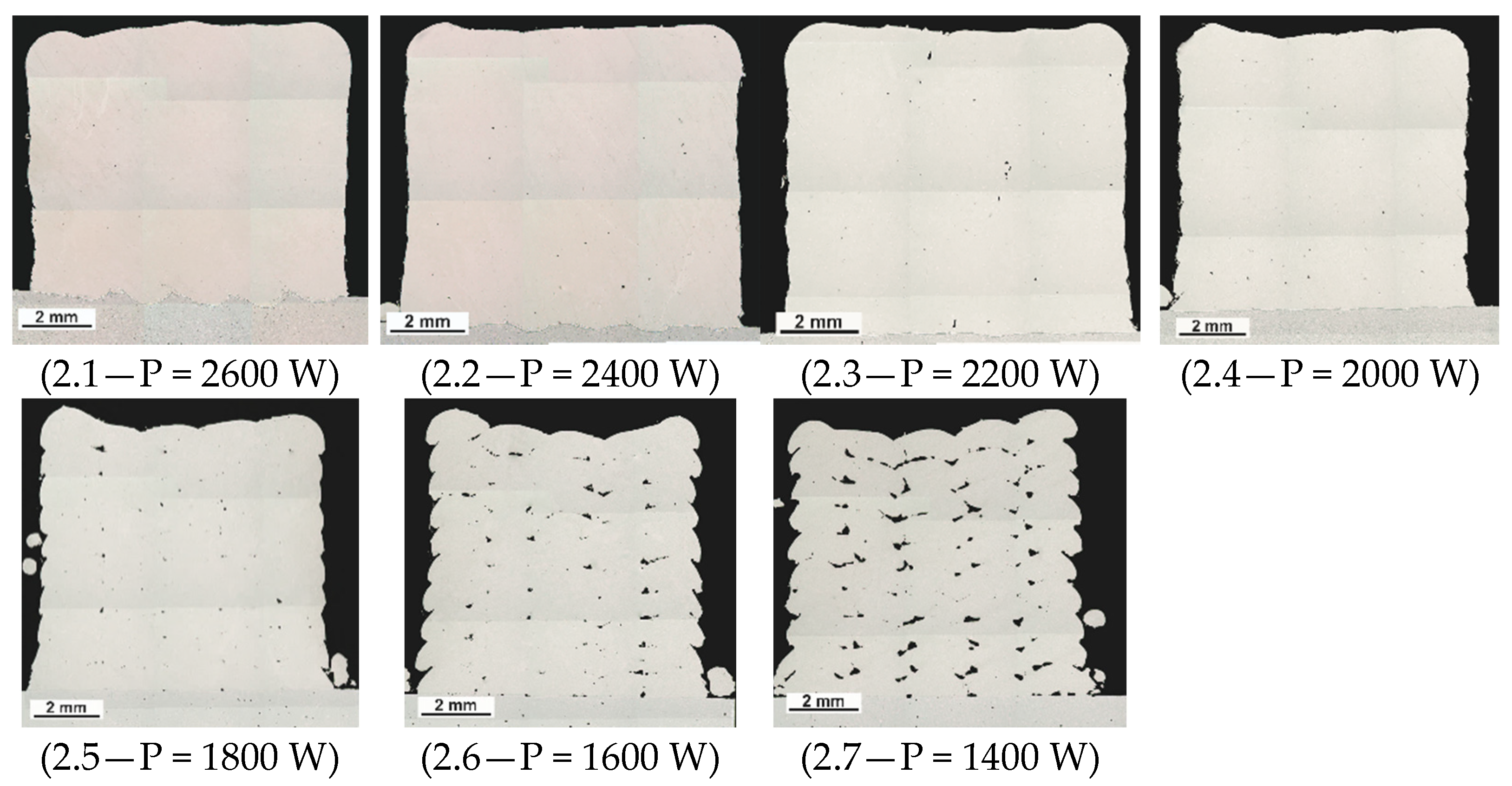
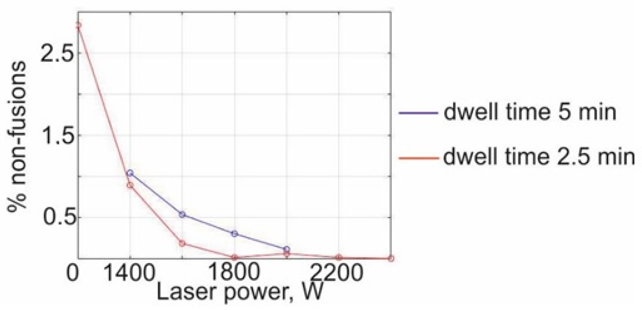
  • When manufacturing large-sized parts by direct laser deposition, it is necessary to set high power values, because low power values lead to the formation of non-fusion.
  • To save time in determining the technological mode, it makes no sense to set the pause between the tracks on the model sample at more than 2.5 min, since the sample has time to cool down and simulate a large-sized part.

Author Contributions

Conceptualization, A.V., A.A. and K.B.; methodology, A.V., A.A. and K.B.; validation, K.B., and R.M.; writing—original draft preparation, A.V.; writing—review and editing, A.V. and K.B; visualization, A.V. and R.M.; supervision, G.T. and K.B. All authors have read and agreed to the published version of the manuscript.

Funding

The reported study was funded by RFBR, project number 19-38-90268.

Institutional Review Board Statement

Not applicable.

Informed Consent Statement

Not applicable.

Data Availability Statement

Not applicable.

Conflicts of Interest

The authors declare no conflict of interest.

References

  1. Murr, L.E.; Gaytan, S.M.; Ramirez, D.A.; Martinez, E.; Hernandez, J.; Amato, K.N.; Shindo, P.W.; Medina, F.R.; Wicker, R.B. Metal Fabrication by Additive Manufacturing Using Laser and Electron Beam Melting Technologies. J. Mater. Sci. Technol. 2012, 28, 1–14. [Google Scholar] [CrossRef]
  2. Turichin, G.A.; Zemlyakov, E.V.; Klimova, O.G.; Babkin, K.D.; Shamray, F.A.; Kolodiajniy, D.Y. Direct laser deposition–per-spective additive technology for aircraft engine. Svarka Diagn. 2015, 3, 54–57. [Google Scholar]
  3. Gu, D. New metallic materials development by laser additive manufacturing. In Laser Surface Engineering; Lawrence, J., Waugh, D.G., Eds.; Elsevier Ltd.: Amsterdam, The Netherlands, 2015; pp. 163–180. [Google Scholar]
  4. Gress, D.R.; Kalafsky, R.V. Geographies of production in 3D: Theoretical and research implications stemming from additive manufacturing. Geoforum 2015, 60, 43–52. [Google Scholar] [CrossRef]
  5. Murr, L.E.; Martinez, E.; Gaytan, S.M.; Ramirez, D.A.; Machado, B.I.; Shindo, P.W.; Martinez, J.L.; Medina, F.; Wooten, J.; Ciscel, D.; et al. Microstructural Architecture, Microstructures, and Mechanical Properties for a Nickel-Base Superalloy Fabricated by Electron Beam Melting. Metals Mater. Trans. A 2011, 42, 3491–3508. [Google Scholar] [CrossRef] [Green Version]
  6. Wilson, J.M.; Piya, C.; Shin, Y.C.; Zhao, F.; Ramani, K. Remanufacturing of turbine blades by laser direct deposition with its energy and environmental impact analysis. J. Clean. Prod. 2014, 80, 170–178. [Google Scholar] [CrossRef]
  7. Yadollahi, A.; Shamsaei, N.; Thompson, S.M.; Seely, D.W. Effects of process time interval and heat treatment on the mechanical and microstructural properties of direct laser deposited 316L stainless steel. Mater. Sci. Eng. A 2015, 644, 171–183. [Google Scholar] [CrossRef]
  8. Saeidi, K.; Gao, X.; Zhong, Y.; Shen, Z. Hardened austenite steel with columnar sub-grain structure formed by laser melting. Mater. Sci. Eng. A 2015, 625, 221–229. [Google Scholar] [CrossRef]
  9. Wei, H.; Mazumder, J.; Debroy, T. Evolution of solidification texture during additive manufacturing. Sci. Rep. 2015, 5, 16446. [Google Scholar] [CrossRef] [PubMed] [Green Version]
  10. Sklyar, M.O.; Turichin, G.A.; Klimova, O.G.; Zotov, O.G.; Topalov, I.K. Microstructure of 316L stainless steel components produced by direct laser deposition. Steel Transl. 2016, 46, 883–887. [Google Scholar] [CrossRef]
  11. Santa-Aho, S.; Kiviluoma, M.; Jokiaho, T.; Gundgire, T.; Honkanen, M.; Lindgren, M.; Vippola, M. Additive Manufactured 316L Stainless-Steel Samples: Microstructure, Residual Stress and Corrosion Characteristics after Post-Processing. Metals 2021, 11, 182. [Google Scholar] [CrossRef]
  12. Zhou, B.; Xu, P.; Li, W.; Liang, Y.; Liang, Y. Microstructure and Anisotropy of the Mechanical Properties of 316L Stainless Steel Fabricated by Selective Laser Melting. Metals 2021, 11, 775. [Google Scholar] [CrossRef]
  13. Qian, S.; Zhang, Y.; Dai, Y.; Guo, Y. Microstructure and Mechanical Properties of Nickel-Based Coatings Fabricated through Laser Additive Manufacturing. Metals 2020, 11, 53. [Google Scholar] [CrossRef]
  14. Ganesh, P.; Giri, R.; Kaul, R.; Sankar, P.R.; Tiwari, P.; Atulkar, A.; Porwal, R.; Dayal, R.; Kukreja, L. Studies on pitting corrosion and sensitization in laser rapid manufactured specimens of type 316L stainless steel. Mater. Des. 2012, 39, 509–521. [Google Scholar] [CrossRef]
  15. Ziętala, M.; Durejko, T.; Polański, M.; Kunce, I.; Płociński, T.; Zieliński, W.; Łazińska, M.; Stępniowski, W.; Czujko, T.; Kurzydłowski, K.J.; et al. The microstructure, mechanical properties and corrosion resistance of 316L stainless steel fabricated using laser engineered net shaping. Mater. Sci. Eng. A 2016, 677, 1–10. [Google Scholar] [CrossRef]
  16. Zhang, K.; Wang, S.; Liu, W.; Shang, X. Characterization of stainless steel parts by Laser Metal Deposition Shaping. Mater. Des. 2014, 55, 104–119. [Google Scholar] [CrossRef]
  17. Turichin, G.A.; Klimova-Korsmik, O.G.; Gushchina, M.O.A.B.; Shalnova, S.A.; Korsmik, R.S.; Cheverikin, V.V.; Tataru, A.S. Features of structure formation in α + β titanium alloys. Procedia CIRP 2018, 74, 188–191. [Google Scholar] [CrossRef]
  18. Klimova-Korsmik, O.; Turichin, G.; Mendagaliyev, R.; Razorenov, S.; Garkushin, G.; Savinykh, A.; Korsmik, R. High-Strain Deformation and Spallation Strength of 09CrNi2MoCu Steel Obtained by Direct Laser Deposition. Metals 2021, 11, 1305. [Google Scholar] [CrossRef]
  19. Vallejo, N.D.; Lucas, C.; Ayers, N.; Graydon, K.; Hyer, H.; Sohn, Y. Process Optimization and Microstructure Analysis to Understand Laser Powder Bed Fusion of 316L Stainless Steel. Metals 2021, 11, 832. [Google Scholar] [CrossRef]
  20. Korsmik, R.; Tsybulskiy, I.; Rodionov, A.; Klimova-Korsmik, O.; Gogolukhina, M.; Ivanov, S.; Zadykyan, G.; Mendagaliev, R. The approaches to design and manufacturing of large-sized marine machinery parts by direct laser deposition. Procedia CIRP 2020, 94, 298–303. [Google Scholar] [CrossRef]
  21. El-Hadad, S.; Khalifa, W.; Nofal, A. Surface modification of investment cast-316L implants: Microstructure effects. Mater. Sci. Eng. C 2015, 48, 320–327. [Google Scholar] [CrossRef] [PubMed]
Figure 1. The robotic complex for direct laser deposition.
Metals 11 01550 g001
Figure 2. Powder 316L: (a) powder particles; (b) particle histogram.
Metals 11 01550 g002
Figure 3. The dimensions (in mm) of the standard model sample and the substrate.
Metals 11 01550 g003
Figure 4. The thin cross-sections of the samples (first series), laser power in the range of P = 2600 W (1.1) to P = 1200 W (1.8).
Metals 11 01550 g004
Figure 6. Macrostructure of samples with different modes, laser power in the range of P = 2600 W (Sample 1.1; Sample 2.1), P = 2200 W (Sample 1.3; Sample 2.3), P = 1800 W (Sample 1.5; Sample 2.5).
Metals 11 01550 g006
Figure 7. Microstructure of samples with different production power, laser power in the range of P = 2600 W (2.1) to P = 1600 W (2.6).
Metals 11 01550 g007aMetals 11 01550 g007b
Figure 8. The non-fusion percentage dependence on the power of laser radiation.
Metals 11 01550 g008
Figure 9. Comparison of thermal cycles of samples with modes 1.3 and 2.3.
Metals 11 01550 g009
Figure 10. Microhardness of the deposited samples: (a) microhardness graph; (b) microhardness scheme.
Metals 11 01550 g010
Table 1. The chemical composition of the 316L.
Material Grade.OHNCSiMnCrNiMoSPFeTi
316L
ASTM A240
˂0.02˂0.0002˂0.02≤0.03≤1.0≤2.016.0–18.010.0–14.02.0–3.0≤0.03≤0.045Bal.˂0.5
316L Powder 0.0210.321.3216.5210.052.080.0220.041-
Table 2. The technological parameters of the deposited samples.
No.1Dwell time = 5 min, velocity = 25 mm/s, width track = 2.5 mm
Samples1.11.21.31.41.51.61.71.8
Power, W26002400220020001800160014001200
No.2Dwell time = 2.5 min, velocity = 25 mm/s, width track = 2.5 mm
Samples2.12.22.32.42.52.62.72.8
Power, W26002400220020001800160014001200
Table 3. Percentage of the non-fusion in the second series of experiments.
Samples Number2.12.22.32.42.52.62.7
% of Non-Fusions0.010.020.060.020.20.92.8
Table 4. Mechanical properties.
SamplesTensile Strength, (MPa)Yield Strength, (MPa)Elongation, (%)Impact Strength, KCU, (J/cm2)
ASTM A24048517040160–180
1.3570272.541160
2.355626939150
Publisher’s Note: MDPI stays neutral with regard to jurisdictional claims in published maps and institutional affiliations.

