Abstract
The light weight of magnesium alloys makes them a promising material in different potential industries, such as aerospace and automobile. In addition, magnesium alloys are attractive materials for biomedical applications due to their biocompatibility with the human body. The applications of these alloys in structural parts require an understanding of their fatigue behavior because they are usually subjected to time-varying loading. Furthermore, notches are inevitable in structural parts. Geometrical discontinuities weaken structures because they act as stress raisers. Localized cyclic plasticity around notches leads to crack formation and final failure. The main objective of this research was to investigate the fatigue failure of ZK60-T5 extrusion in the presence of a notch. U-notched specimens with a diameter of 16 mm, notch radius of 1.5 mm, and notch depth of 1.5 mm were machined along the extrusion direction. Cyclic tests were performed under completely reversed cyclic loading and ambient conditions. The results obtained from the cyclic tests of the U-notched specimens were compared with those of unnotched and V-notched specimens to assess the effects of both the presence and the geometry of a notch on fatigue life. The strain energy density approach was successfully used to analyze the fatigue behavior of the U-notch specimens.
1. Introduction
The applications of magnesium alloys are increasing in diverse industries, such as aerospace, automotive, medical, and electronics. The light weight of magnesium makes it extremely attractive for transportation industries. The automobile and aircraft industries, which are motivated by fuel economy and reduction in gas emission, are leading the development of new magnesium alloys with high strength and corrosion and creep resistance. Multinational research initiatives, such as the Magnesium Front End Research and Development project between Canada, the USA, and China, were established to enable major applications of magnesium alloys in the body structure of the front end in automobiles [1,2,3]. In addition, high-strength and high-corrosion-resistant magnesium alloys, such as the Mg-Nd-Y-Zr (WE series) alloys, are used in aircraft, helicopters [4,5], and military jet fighters [6]. Magnesium alloys have excellent electromagnetic interference shielding properties, making them suitable for electronic applications [7]. Furthermore, magnesium alloys are one of the best materials biocompatible with the human body [8,9].
Due to their potential, researchers around the globe are investigating different magnesium alloys under various type of loading and conditions [10,11,12,13,14]. Normal, compressive, and shear behaviors clearly show that magnesium exhibits distinct characteristics [15,16,17,18,19] from those of conventional steel and aluminum alloys. The close-packed hexagonal lattice structure of magnesium causes it to deform plastically under two different mechanisms: slipping and twinning [20,21,22,23,24,25]. Texture analyses clearly show that wrought magnesium alloys, produced by extrusion, rolling, or forging, possess strong texture, with the basal planes parallel to the working direction and the c-axis normal to it [26,27]. As a result, application of cyclic axial loading along the working direction results in an asymmetric cyclic behavior due to the involvement of multiple plastic deformation mechanisms, such as slipping, twinning, and detwinning. The complex cyclic behavior of wrought magnesium alloys cannot be simulated with existing commercial finite element packages. Therefore, user-defined material subroutines need to be developed to capture the cyclic behavior of magnesium alloys [28,29,30,31].
The high-cycle fatigue of ZK60 and ZK60-T6 magnesium extrusion was investigated by Liu et al. using a rotating–bending experiment [32]. Their study showed that T5 heat treatment improves both monotonic, such as yield and ultimate tensile strengths and elongation, and cyclic properties, such as fatigue strength. Liu et al. found that the fatigue limits at 107 cycles are 150 MPa and 140 MPa for ZK60 and ZK60-T5, respectively. The very-high-cycle fatigue (VHCF) of ZK60 extrusion was investigated by He et al. [33] using push–pull loading conditions. They performed tests until 109 cycles without failure. He et al. observed two zones with different morphological characteristics corresponding to crack initiation and early growth. They also observed that the morphology of the crack initiation zone is influenced by the interaction between the twinning bands and the plastic zone ahead of the crack tip. The directional stress-controlled behavior of ZK60 extrusion was characterized by Pahlevanpour et al. [34] along the extrusion and radial directions. A significant observation of this study was that, unlike the extrusion direction, the cyclic behavior along the radial direction is symmetric due to the unidirectional orientation of the hexagonal close-packed (HCP) crystals. In addition, the stress–life curves show that extrusion direction exhibit higher fatigue resistance than the radial direction. Pahlevanpour et al. [34] explained that strain energy density, represented by the size of the hysteresis loops, for tests performed at the same stress amplitude is higher for specimens machined along the radial direction than that for the extrusion direction. Therefore, they used the strain energy density [35] proposed by Jahed and Varavani to model the fatigue behavior of the material. Their predictions for the fatigue life of the material under stress- and strain-controlled loading [36] along the radial and extrusion directions fall within ±2x scatter bands.
Albinmousa et al. [37] used the strain energy density approach (SED) developed by Lazzarin and Zambardi [38] to study the fatigue behavior of V-notched ZK60-T5 magnesium extrusion. They showed that fatigue life can be successfully correlated with the average strain density calculated over a control volume ahead of the notch. The SED approach has been shown to be capable of estimating the fatigue failure for different materials and notched geometries [39,40,41,42,43,44,45]. The main objective of this research is to investigate the fatigue behavior of U-notched specimens machined from ZK60-T5 magnesium extrusion. The effects of the presence and geometry of a notch on the fatigue life of the material is discussed. The local strain energy density approach was used to estimate the fatigue life within ±2x scatter bands.
2. Materials and Experiments
2.1. Material
The material used for this investigation was ZK60-T5 magnesium extrusion. The material was acquired from SMW Engineering, Russia, as 1000 mm rods with a diameter of 150 mm. This alloy has chemical compositions as listed in Table 1. The microstructure of the material of the plane normal to the extrusion is shown in Figure 1. This microstructure was observed by cutting small metallurgical samples that were mounted and then polished using 240, 320, 400, and 600 grit size abrasive papers. An etchant was prepared using 5 g picric and 5 mL acetic acid, 10 mL distilled water, and 100 mL ethanol. After etching the samples, the micrographs were taken using an Olympus DSX-510 digital microscope. The microstructure consists of large and small grains with an average grain size of 9.52 µm ± 1.89 µm. This structure is commonly observed in ZK60, investigated elsewhere [46], and in other wrought magnesium alloys, such as AZ31B [47,48], AZ61A [49], and AZ80 [50].

Table 1.
Chemical compositions (wt%) of ZK60A-T5.
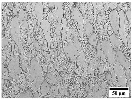
Figure 1.
Microstructure of ZK60-T5.
2.2. Monotonic and Cyclic Behaviors
A representative monotonic tensile stress–strain curve for the material is shown in Figure 2. According to Figure 2, the material exhibits conventional power-type hardening. This is expected because it is known that slipping is the major plastic deformation mechanism when tensile loading is applied parallel to the extrusion direction [24]. Loading that is oriented such that extension is caused along the c-axis produces () tension twins that have a low critical resolved shear stress value. This effect can be observed when a specimen that is machined along the working direction is subjected to compressive loading. In this case, the resulting stress–strain curve shows a sigmoidal-type behavior. By contrast, application of tensile loading on a specimen machined along the working direction only activates slipping mechanisms. Therefore, the tensile stress–strain curve for such a case shows conventional, power-hardening-type behavior [15]. Among the different slip systems in magnesium, such as () prismatic, and pyramidal () and (), the basal () has the lowest critical resolved shear stress. It was observed that basal planes can only accommodate about 8% elongation if they are tilted toward the loading axis by more than 16.5° [51]. Additional elongation reaching 20% can be obtained when the () prismatic becomes dominant [51]. The ratio of the critical resolved shear stress of prismatic to basal slip is estimated to be between 1.5 and 2.5 [52,53].
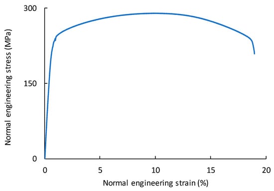
Figure 2.
Engineering stress–strain curve for ZK60-T5 along the extrusion direction.
The cyclic behavior of the material has been investigated under strain-controlled axial, shear, and multiaxial cyclic loading conditions [54]. This alloy has also been tested under uniaxial strain-controlled fatigue loading by Pahlevanpour et al. [36,55]. Figure 3a indicates that the strain–life curves obtained by Albinmousa et al. [54] and Pahlevanpour et al. [36,55] are significantly comparable. Therefore, the stress–life curve obtained by Pahlevanpour et al. [34,55], shown in Figure 3b, was used for this investigation. In general, the cyclic behavior of ZK60 magnesium extrusion is similar to other wrought magnesium, such as AZ31B [15,48], AZ61 [49], AM30 [26], and AZ80 [50]. The development of strong texture as a result of either the extrusion, rolling, or forging process causes the material to exhibit tension–compression asymmetry due to slipping in tension reversal and twinning in compression reversal. A sigmoidal-type behavior is usually observed in the tension reversal as twinned lattices are detwinned after compression. While such a distinct behavior is commonly observed in cyclic strain-controlled experiments, it also prevails under cyclic stress-controlled loading when local strain is measured by an extensometer [34] or digital image correlation [56].
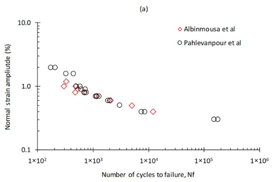
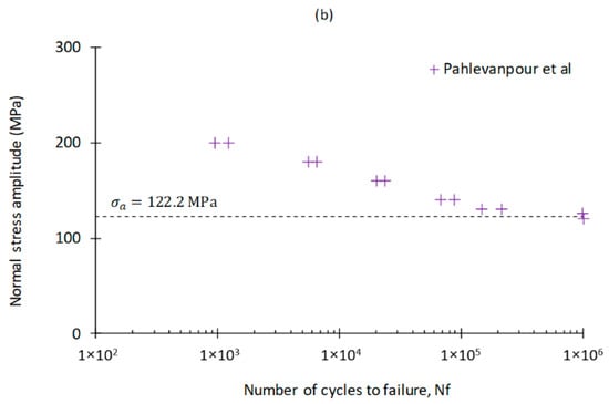
Figure 3.
Cyclic behavior of ZK60 extrusion. (a) Normal strain–life curves [36], reproduced from [36], with permission from Elsevier, 2020. and (b) stress–life curve [34], reproduced from [34], with permission from Elsevier, 2020.
2.3. Fatigue Experiments
Fatigue experiments were performed on notched ZK60-T5 specimens. Blanks with an 18 mm × 18 mm cross section and a length of 140 mm were cut along the extrusion direction of the rod. These blanks were then machined to round specimens with a diameter of 16 mm and length of 130 mm. U-notches were machined in the middle of the specimens with a depth of 1.5 mm and a radius of 1.5 mm, as shown in Figure 4. Completely reversed stress-controlled cyclic axial experiments, , were performed on six U-notched specimens. The notched specimens were subjected to force amplitudes between 16 and 11.5 kN corresponding to nominal stress amplitudes of 57.2 and 79.6 MPa at the gripping section, respectively. These amplitudes resulted in a fatigue life range between nearly 104 and 106 cycles. Frequencies between 1.0 and 30 Hz were used for the experiments. All specimens were loaded until complete fracture by separation.

Figure 4.
Geometry and sizes of U-notched specimens.
In addition, the fatigue experiment on V-notched specimens machined from the same material with the same outside diameter and depth but with a V-notch having an opening angle of 60° and notch radius of 0.8 mm performed by Albinmousa et al. [37] was considered in this study for comparison. This experiment was under completely reversed stress-controlled conditions. These specimens were loaded with a force amplitude between 14 and 10.5 kN, which resulted in fatigue lives between 17 × 103 and 1.1 × 10⁶ cycles.
3. Strain Energy Density Approach (SED)
Lazzarin and Zambardi [38] developed the strain energy density criterion used in this investigation. This criterion predicts that failure occurs when the total average strain energy density over a specific control volume ahead of the notch tip reaches a critical energy. For a cyclic loading condition, the average strain energy range in the control volume is compared to a critical strain energy value to estimate failure such that
where is the fatigue limit obtained from an unnotched specimen and is the elastic modulus. The strain energy density for blunted V-notched or U-notched samples subjected to cyclic axial loading is [57,58]
where is the range of the mode I notch stress intensity factor and is a geometrical parameter that depends on the opening angle of the notch and Poisson’s ratio [38]. is William’s eigenvalue, equal to 0.5 for a U-notch [59,60]. The material parameter is the radius of the control volume surrounding the notch, as illustrated in Figure 5, and is calculated using
where is the range of the notch stress intensity factor (NSIF). It can be seen from Figure 5 that the control volume has a crescent shape. In fact, the control volume is constructed by a circle of radius , where
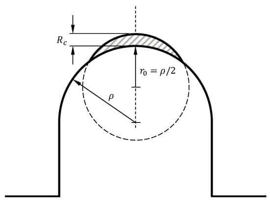
Figure 5.
Control volume for a U-notch under mode I loading.
For a U-notched specimen with , Equation (4) yields , as indicated in Figure 5. Based on the strain energy density criterion, the critical radius is considered a material property [61]. If all required variables are known, the critical radius can be determined using Equation (3). However, a more convenient procedure can be followed to determine the critical radius using finite element analysis, which is explained in the next section.
4. Finite Element Analysis
ANSYS software was used to perform finite element analysis. Due to double symmetry, only one quarter of the specimen needs to be considered for finite element analysis. In addition, the strain energy density criterion only requires linear elastic analysis. Therefore, 2D axisymmetric linear elastic analyses were performed to evaluate the strain energy density. Plane 83 element with 8 nodes and axisymmetric capability was used. An average element size of mm2 around the notch region was used to smoothly capture the curvature of the notch. Symmetric and axisymmetric boundary conditions were defined as illustrated in Figure 6. ZK60 was modeled as a linear elastic material with a modulus of elasticity of 44.3 GPa and a Poisson’s ratio of 0.35.
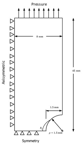
Figure 6.
Schematic of the finite element model.
As stated in the previous section, the critical radius was determined using finite element analysis. It should be noted that because the critical radius is a material property, the value of mm, determined by Albinmousa et al. [37], can be used in this investigation. This is because they investigated the fatigue of V-notched specimens for the same material. However, the procedure for obtaining using finite element was followed for a U-notched specimen considered in this research. First, a reference fatigue life of cycles was considered. Second, the applied stress range corresponding to the reference fatigue life from an unnotched specimen was found to be MPa based on the experimental work of Pahlevanpour et al. on the same alloy [34,55]. This allows for the determination of the critical strain energy value using Equation (1), which gives MJ/m3. Third, the experimental results performed on U-notched specimens for this investigation show that a force amplitude of 11.5 kN, equivalent to a nominal stress range of 114.4 MPa at the gripping section, corresponds to a fatigue life of cycles. As a result, a nominal stress of 114.4 MPa was applied on the U-notched geometry shown in Figure 6. Then, the critical radius was varied until the corresponding average strain energy density in the control volume is MJ/m3. Figure 7 shows how this process is used to determine the critical radius, which yielded a value of mm, which is only 4.2% higher than that obtained by Albinmousa et al. [37] considering V-notch geometry.
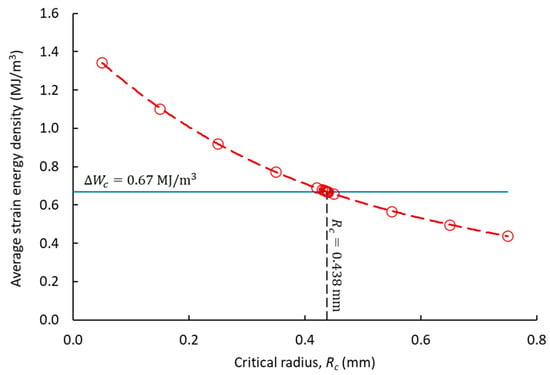
Figure 7.
Determination of the critical radius.
Once the value of the critical radius is obtained, it is used for analyzing the remaining specimens. This was done using the applied stress range used in the experiment and calculating the corresponding average strain energy density in the control volume. Figure 8a,b shows the stress distribution along the y-direction surrounding the notch region and the elastic strain energy in the control volume for the U-03 specimen obtained by applying a nominal stress range of 159.2 MPa.
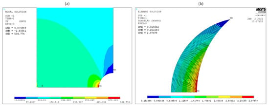
Figure 8.
Finite element results. (a) Normal stress along the y-direction. (b) Elastic strain energy in the control volume.
5. Results and Discussion
The fatigue results for U-notched specimens obtained in this investigation are listed in Table 2. In addition, the results for V-notched specimens obtained by Albinmousa et al. [37] are also listed in the table for comparison. The nominal and net section stresses in the table are calculated at the gripping, mm, and net, mm, sections, respectively.

Table 2.
Fatigue test results for U- and V-notches with . The nominal stress is calculated at the gripping section (D = 16 mm) of the specimen, while the net section stress is calculated at the net section (d = 13 mm). V-notched data were obtained from Albinmousa et al. [37]. Reproduced from [37], with permission from Elsevier, 2020.
The effects of the presence of a notch as well as the notch geometry on fatigue life are shown in Figure 9. In this figure, the net section stress amplitudes for unnotched specimens are calculated at the gauge section of a dog-bone specimen with a rectangular geometry [55]. On the other hand, the net section stress amplitudes for U- and V-notched specimens are calculated at the net section having a diameter of 13 mm. It is seen from this figure that the presence of a notch has a significant influence on fatigue life. For example, while applying a net section stress amplitude of 120.5 MPa on a U-notched specimen results in a fatigue of about cycles, an unnotched specimen subjected to the same stress amplitude can sustain cycles without failure. Comparison of the fatigue behaviors of the U- and V-notched specimens in the same figure shows that U-notched specimens have better fatigue resistance than their V-notched counterparts.
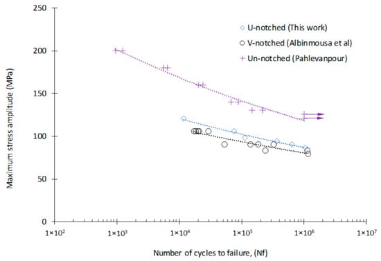
Figure 9.
Effects of a notch and the notch geometry on fatigue life [34]. Reproduced from [34], with permission from Elsevier, 2020.
It is seen from Table 2 that more duplicates were tested using V-notched than U-notched specimens given more confidence in the value of the critical radius obtained using the results of V-notched specimens, although a difference of 4.2% is negligible. In addition, to have a common background for comparison, a single value of the critical radius, mm, was used for evaluating the average strain energy density for both the U- and the V-notched specimens. Figure 10 shows the correlation between the strain energy density and fatigue life of unnotched and U- and V-notched specimens using a power-type equation with an R2 = 0.972. It is evident from this figure that the strain energy density (SDE) criterion can correlate the data from all specimens into a single and narrow scatter band. It is important to note that the strain energy densities for unnotched specimens were evaluated using Equation (1). On the other hand, the strain energy densities for all notched specimens were averaged over the control volumes for each specimen.
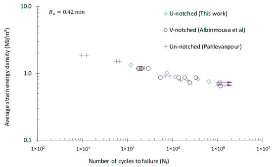
Figure 10.
Correlation of the strain energy density and fatigue life of unnotched and U- and V-notched specimens [34]. Reproduced from [34], with permission from Elsevier, 2020.
Two observations can be made from the results presented in Figure 10. First, strain energy density is a suitable fatigue damage parameter for analyzing notched magnesium specimens. Second, the fatigue life of notched specimens can be estimated using the fatigue data of unnotched specimens. As for fatigue damage parameters, they are classified into stress-, strain-, or energy-based. Well-known stress- or strain-based parameters such as Carpinteri [62], Fatemi–Socie [63], or Smith–Watson–Topper [64] require a knowledge of local stress and strain states at the notch root. Similarly, energy-based models such as Jahed–Varvani [35] require a knowledge of cyclic hysteresis loops at the notch root to quantify fatigue damage. In the case of axial cyclic loading, notch rules such as Neuber’s [65] or Glinka’s [66,67] can be used to estimate the local stress–strain state based on applied nominal loads. In fact, this approach was successfully used by Roostaei et al. [56] to analyze the cyclic axial fatigue of a rolled ZEK100-F magnesium notched specimen. The authors used Neuber’s and Glinka’s rules to estimate the local cyclic stress–strain state at the notch root of a plate with a central hole. Roostaei et al. [56] investigated constant and variable amplitude loading conditions. The estimated strain states for different conditions were verified using a digital image correlation system. Using the Smith–Watson–Topper model, Roostaei et al. were able to estimate the fatigue life within a conservative scatter band. Still, the method adopted by Roostaei et al. [56] requires a numerical procedure to be developed to model the asymmetric hysteresis loop of wrought magnesium alloys. Alternatively, as discussed in the introduction, a user material cyclic plasticity model is required to estimate the local stress–strain state at the notch root.
The strain energy density approach explained in Section 3 offers a simpler and more practical alternative with a promising reliability, as observed in Figure 10. To estimate the fatigue life of the U- and V-notched specimens examined in this work, the energy–life data for unnotched specimens were fitted with a power-type equation as shown in Figure 11. After that, the energy–life equation obtained was used to estimate the cyclic axial fatigue lives of U- and V-notched specimens. A comparison between experimental and estimated fatigue lives of all notched specimens is shown in Figure 12. This figure shows that estimations fall within 2x scatter bands, which clearly supports the capability of the strain energy density criterion in estimating the fatigue lives of different ZK60 notched geometries.
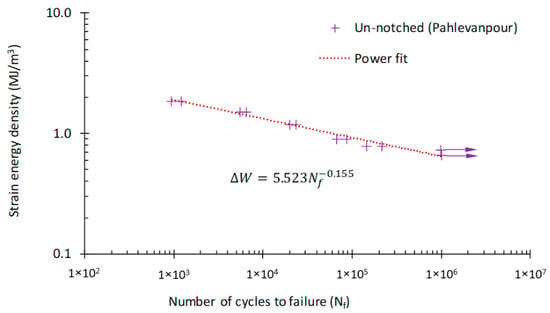
Figure 11.
Energy–life curve for unnotched specimens [34]. Reproduced from [34], with permission from Elsevier, 2020.
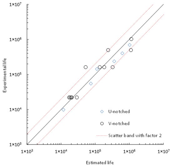
Figure 12.
Estimation of fatigue life of U- and V-notched specimens based on the strain energy density criterion.
6. Conclusions
The fatigue of U-notched specimens machined from ZK60-T5 magnesium extrusion was investigated. Stress-controlled cyclic axial experiments were performed under completely reversed loading conditions covering a life range between and cycles. The results obtained were compared to those of V-notched tests performed on the same material. It is evident that the presence of a notch is detrimental to fatigue life. It was also observed that the notch geometry influences the fatigue life. The strain energy density (SDE) approach was successfully used to correlate the fatigue life of unnotched and U- and V-notched specimens using a critical radius of mm. The SED approach was shown to be a reliable yet simple and practical tool for analyzing the fatigue of wrought magnesium alloys. This approach offers a solution without the need for an explicit treatment of the complex cyclic behavior of wrought magnesium, which is known to involve multiple plastic deformation mechanisms such as slipping and twinning.
Funding
This research received no external funding.
Institutional Review Board Statement
Not applicable.
Informed Consent Statement
Not applicable.
Data Availability Statement
The data presented in this study are available on request from the corresponding author.
Acknowledgments
The author would like to acknowledge the support of the King Fahd University of Petroleum & Minerals (KFUPM).
Conflicts of Interest
The author declares no conflict of interest.
References
- Albinmousa, J.; Pascu, A.; Jahed, H.; Horstemeyer, M.F.; Luo, A.; Chen, D.; Lambert, S.; Jordon, J.; Begum, S.; Su, X.; et al. Monotonic and Fatigue Behavior of Magnesium Extrusion Alloy AM30: An International Benchmark Test in the “Magnesium Front End Research and Development Project”; SAE International: Warrendale, PA, USA, 2010. [Google Scholar]
- Luo, A.A.; Nyberg, E.A.; Sadayappan, K.; Shi, W. Magnesium Front End Research and Development: A Canada-China-USA Collaboration. In Essential Readings in Magnesium Technology; Mathaudhu, S.N., Luo, A.A., Neelameggham, N.R., Nyberg, E.A., Sillekens, W.H., Eds.; Springer International Publishing: Cham, Switzerland, 2016; pp. 41–48. ISBN 978-3-319-48099-2. [Google Scholar]
- Forsmark, J.H.; Li, M.; Su, X.; Wagner, D.A.; Zindel, J.; Luo, A.A.; Quinn, J.F.; Verma, R.; Wang, Y.-M.; Logan, S.D.; et al. The USAMP Magnesium Front End Research and Development Project—Results of the Magnesium “Demonstration” Structure. In Magnesium Technology 2014; Alderman, M., Manuel, M.V., Hort, N., Neelameggham, N.R., Eds.; Springer International Publishing: Cham, Switzerland, 2016; pp. 517–524. ISBN 978-3-319-48231-6. [Google Scholar]
- Aghion, E.; Bronfin, B.; Eliezer, D. The role of the magnesium industry in protecting the environment. J. Mater. Process. Technol. 2001, 117, 381–385. [Google Scholar] [CrossRef]
- The Metallurgy of Light Alloys: This Vol. Contains the Keynote Papers, Supporting Papers Presented at the Spring Residential Conference held at the University of Technology Loughborough from 24–26 March 1983; Institution of Metallurgists, Ed.; Spring Residential Conference/Institution of Metallurgists; Institution of Metallurgists: London, UK, 1983; ISBN 978-0-901462-21-3. [Google Scholar]
- Mathaudhu, S.N.; Nyberg, E.A. Magnesium alloys in US Military applications: Past, current and future solutions. In Essential Readings in Magnesium Technology; Springer: Berlin/Heidelberg, Germany, 2016; pp. 71–76. [Google Scholar]
- Aghion, E.; Bronfin, B. Magnesium Alloys Development towards the 21st Century. MSF 2000, 350–351, 19–30. [Google Scholar] [CrossRef]
- Peron, M.; Torgersen, J.; Berto, F. Mg and Its Alloys for Biomedical Applications: Exploring Corrosion and Its Interplay with Mechanical Failure. Metals 2017, 7, 252. [Google Scholar] [CrossRef]
- Albinmousa, J. Fatigue of Magnesium-Based Materials. In Magnesium-The Wonder Element for Engineering/Biomedical Applications; IntechOpen: London, UK, 2020. [Google Scholar]
- Cheng, Y.L.; Qin, T.W.; Wang, H.M.; Zhang, Z. Comparison of corrosion behaviors of AZ31, AZ91, AM60 and ZK60 magnesium alloys. Trans. Nonferrous Metals Soc. China 2009, 19, 517–524. [Google Scholar] [CrossRef]
- Liu, W.; Dong, J.; Zhang, P.; Zhai, C.; Ding, W. Effect of Shot Peening on Surface Characteristics and Fatigue Properties of T5-Treated ZK60 Alloy. Mater. Trans. 2009, 50, 791–798. [Google Scholar] [CrossRef]
- Fouad, Y.; El Batanouny, M. Effect of surface treatment on wear behavior of magnesium alloy AZ31. Alex. Eng. J. 2011, 50, 19–22. [Google Scholar] [CrossRef]
- Silva, E.P.; Leiva, D.R.; Pinto, H.C.; Floriano, R.; Neves, A.M.; Botta, W.J. Effects of friction stir processing on hydrogen storage of ZK60 alloy. Int. J. Hydrog. Energy 2018, 43, 11085–11091. [Google Scholar] [CrossRef]
- Behravesh, S.B.; Jahed, H.; Lambert, S. Characterization of magnesium spot welds under tensile and cyclic loadings. Mater. Des. 2011, 32, 4890–4900. [Google Scholar] [CrossRef]
- Albinmousa, J.; Jahed, H.; Lambert, S. Cyclic axial and cyclic torsional behaviour of extruded AZ31B magnesium alloy. Int. J. Fatigue 2011, 33, 1403–1416. [Google Scholar] [CrossRef]
- Toscano, D.; Behravesh, S.B.; Shaha, S.K.; Jahed, H.; Williams, B. Characterization of closed-die forged AZ31B under pure axial and pure shear loading. Int. J. Fatigue 2020, 139, 105754. [Google Scholar] [CrossRef]
- Peron, M.; Bertolini, R.; Ghiotti, A.; Torgersen, J.; Bruschi, S.; Berto, F. Enhancement of stress corrosion cracking of AZ31 magnesium alloy in simulated body fluid thanks to cryogenic machining. J. Mech. Behav. Biomed. Mater. 2020, 101, 103429. [Google Scholar] [CrossRef] [PubMed]
- Wu, W.; Stoica, A.; Yu, D.; Frost, M.; Skorpenske, H.; An, K. Bending Behavior of a Wrought Magnesium Alloy Investigated by the In Situ Pinhole Neutron Diffraction Method. Crystals 2018, 8, 348. [Google Scholar] [CrossRef]
- Xiong, Y.; Jiang, Y. Compressive deformation of rolled AZ80 magnesium alloy along different material orientations. J. Mater. Sci. 2020, 55, 4043–4053. [Google Scholar] [CrossRef]
- Wu, L.; Agnew, S.R.; Ren, Y.; Brown, D.W.; Clausen, B.; Stoica, G.M.; Wenk, H.R.; Liaw, P.K. The effects of texture and extension twinning on the low-cycle fatigue behavior of a rolled magnesium alloy, AZ31B. Mater. Sci. Eng. A 2010, 527, 7057–7067. [Google Scholar] [CrossRef]
- Barnett, M. Twinning and the ductility of magnesium alloys Part I: “Tension” twins. Mater. Sci. Eng. A 2007, 464, 1–7. [Google Scholar] [CrossRef]
- Barnett, M.R. Twinning and the ductility of magnesium alloys: Part II.“Contraction” twins. Mater. Sci. Eng. A 2007, 464, 8–16. [Google Scholar] [CrossRef]
- Staroselsky, A.; Anand, L. A constitutive model for hcp materials deforming by slip and twinning: Application to magnesium alloy AZ31B. Int. J. Plast. 2003, 19, 1843–1864. [Google Scholar] [CrossRef]
- Lou, X.Y.; Li, M.; Boger, R.K.; Agnew, S.R.; Wagoner, R.H. Hardening evolution of AZ31B Mg sheet. Int. J. Plast. 2007, 23, 44–86. [Google Scholar] [CrossRef]
- Tomé, C.N.; Kaschner, G.C. Modeling texture, twinning and hardening evolution during deformation of hexagonal materials. In Materials Science Forum; Elsevier: Amsterdam, The Netherlands, 2005; Volume 495–497, pp. 1001–1006. [Google Scholar]
- Roostaei, A.A.; Jahed, H. Role of loading direction on cyclic behaviour characteristics of AM30 extrusion and its fatigue damage modelling. Mater. Sci. Eng. A 2016, 670, 26–40. [Google Scholar] [CrossRef]
- Xiong, Y.; Yu, Q.; Jiang, Y. An experimental study of cyclic plastic deformation of extruded ZK60 magnesium alloy under uniaxial loading at room temperature. Int. J. Plast. 2014, 53, 107–124. [Google Scholar] [CrossRef]
- Behravesh, S.B. Fatigue Characterization and Cyclic Plasticity Modeling of Magnesium Spot-Welds; University of Waterloo: Waterloo, ON, Canada, 2013. [Google Scholar]
- Noban, M.; Albinmousa, J.; Jahed, H.; Lambert, S. A continuum-based cyclic plasticity model for AZ31B magnesium alloy under proportional loading. In Procedia Engineering; Elsevier: Amsterdam, The Netherlands, 2011; Volume 10, pp. 1366–1371. [Google Scholar]
- Behravesh, S.B.; Jahed, H.; Lambert, S.B.; Chengji, M. Constitutive Modeling for Cyclic Behavior of AZ31B Magnesium Alloy and its Application. Adv. Mater. Res. 2014, 891, 809–814. [Google Scholar] [CrossRef]
- Roostaei, A.A.; Jahed, H. A cyclic small-strain plasticity model for wrought Mg alloys under multiaxial loading: Numerical implementation and validation. Int. J. Mech. Sci. 2018, 145, 318–329. [Google Scholar] [CrossRef]
- Liu, W.C.; Dong, J.; Zhang, P.; Yao, Z.Y.; Zhai, C.Q.; Ding, W.J. High cycle fatigue behavior of as-extruded ZK60 magnesium alloy. J. Mater. Sci. 2009, 44, 2916–2924. [Google Scholar] [CrossRef]
- He, C.; Liu, Y.; Li, J.; Yang, K.; Wang, Q.; Chen, Q. Very-high-cycle fatigue crack initiation and propagation behaviours of magnesium alloy ZK60. Mater. Sci. Technol. 2018, 34, 639–647. [Google Scholar] [CrossRef]
- Pahlevanpour, A.H.; Behravesh, S.B.; Adibnazari, S.; Jahed, H. Characterization of Anisotropic Behaviour of ZK60 Extrusion under Stress-control Condition and Notes on Fatigue Modeling. Int. J. Fatigue 2019, 127, 101–109. [Google Scholar] [CrossRef]
- Jahed, H.; Varvani-Farahani, A. Upper and lower fatigue life limits model using energy-based fatigue properties. Int. J. Fatigue 2006, 28, 467–473. [Google Scholar] [CrossRef]
- Pahlevanpour, A.H.; Karparvarfard, S.M.H.; Shaha, S.K.; Behravesh, S.B.; Adibnazari, S.; Jahed, H. Anisotropy in the quasi-static and cyclic behavior of ZK60 extrusion: Characterization and fatigue modeling. Mater. Des. 2018, 160, 936–948. [Google Scholar] [CrossRef]
- Albinmousa, J.; Peron, M.; Jose, J.; Abdelaal, A.F.; Berto, F. Fatigue of V-notched ZK60 magnesium samples: X-ray damage evolution characterization and failure prediction. Int. J. Fatigue 2020, 139, 105734. [Google Scholar] [CrossRef]
- Lazzarin, P.; Zambardi, R. A finite-volume-energy based approach to predict the static and fatigue behavior of components with sharp V-shaped notches. Int. J. Fract. 2001, 112, 275–298. [Google Scholar] [CrossRef]
- Campagnolo, A.; Razavi, S.M.J.; Peron, M.; Torgersen, J.; Berto, F. Mode II brittle fracture: Recent developments. Frat. Integr. Strutt. 2017, 11, 181–188. [Google Scholar] [CrossRef]
- Razavi, S.M.J.; Peron, M.; Torgersen, J.; Berto, F. Notched graphite under multiaxial loading. Frat. Integr. Strutt. 2017, 11, 424–431. [Google Scholar] [CrossRef]
- Peron, M.; Razavi, S.M.J.; Berto, F.; Torgersen, J. Notch stress intensity factors under mixed mode loadings: An overview of recent advanced methods for rapid calculation. Frat. Integr. Strutt. 2017, 11, 196–204. [Google Scholar] [CrossRef]
- Peron, M.; Razavi, S.; Torgersen, J.; Berto, F. Fracture Assessment of PEEK under Static Loading by Means of the Local Strain Energy Density. Materials 2017, 10, 1423. [Google Scholar] [CrossRef] [PubMed]
- Peron, M.; Razavi, S.M.J.; Berto, F.; Torgersen, J.; Mutignani, F. Local strain energy density for the fatigue assessment of hot dip galvanized welded joints: Some recent outcomes. Frat. Integr. Strutt. 2017, 11, 205–213. [Google Scholar] [CrossRef]
- Carpinteri, A.; Berto, F.; Campagnolo, A.; Fortese, G.; Ronchei, C.; Scorza, D.; Vantadori, S. Fatigue assessment of notched specimens by means of a critical plane-based criterion and energy concepts. Theor. Appl. Fract. Mech. 2016, 84, 57–63. [Google Scholar] [CrossRef]
- Vantadori, S.; Carpinteri, A.; Fortese, G.; Ronchei, C.; Scorza, D.; Zanichelli, A. Fatigue lifetime evaluation of notched components: Implementation of the control volume concept in a strain-based LCF criterion. Theor. Appl. Fract. Mech. 2018, 97, 400–408. [Google Scholar] [CrossRef]
- Xiong, Y.; Yu, Q.; Jiang, Y. Deformation of extruded ZK60 magnesium alloy under uniaxial loading in different material orientations. Mater. Sci. Eng. A 2018, 710, 206–213. [Google Scholar] [CrossRef]
- Al Bin Mousa, J. Multiaxial Fatigue Characterization and Modeling of AZ31B Magnesium Extrusion; University of Waterloo: Waterloo, ON, Canada, 2011. [Google Scholar]
- Albinmousa, J.; Jahed, H.; Lambert, S. Cyclic behaviour of wrought magnesium alloy under multiaxial load. Int. J. Fatigue 2011, 33, 1127–1139. [Google Scholar] [CrossRef]
- Zhang, J.; Yu, Q.; Jiang, Y.; Li, Q. An Experimental Study of Cyclic Deformation of Extruded AZ61A Magnesium Alloy. Int. J. Plast. 2011, 27, 768–787. [Google Scholar] [CrossRef]
- Gryguć, A.; Behravesh, S.B.; Shaha, S.K.; Jahed, H.; Wells, M.; Williams, B.; Su, X. Multiaxial cyclic behaviour of extruded and forged AZ80 Mg alloy. Int. J. Fatigue 2019, 127, 324–337. [Google Scholar] [CrossRef]
- Koike, J.; Ohyama, R. Geometrical criterion for the activation of prismatic slip in AZ61 Mg alloy sheets deformed at room temperature. Acta Mater. 2005, 53, 1963–1972. [Google Scholar] [CrossRef]
- Koike, J.; Kobayashi, T.; Mukai, T.; Watanabe, H.; Suzuki, M.; Maruyama, K.; Higashi, K. The activity of non-basal slip systems and dynamic recovery at room temperature in fine-grained AZ31B magnesium alloys. Acta Mater. 2003, 51, 2055–2065. [Google Scholar] [CrossRef]
- Agnew, S.R.; Duygulu, Ö. Plastic anisotropy and the role of non-basal slip in magnesium alloy AZ31B. Int. J. Plast. 2005, 21, 1161–1193. [Google Scholar] [CrossRef]
- Albinmousa, J.; Adinoyi, M.J.; Merah, N. Multiaxial fatigue of extruded ZK60 magnesium alloy. Fatigue Fract. Eng. Mater. Struct. 2019. [Google Scholar] [CrossRef]
- Pahlevanpour, A. Role of Loading Direction on Fatigue Behavior of Smooth and Notched ZK60 Extrusion; UWSpace: Madison, WI, USA, 2018. [Google Scholar]
- Roostaei, A.A.; Ling, Y.; Jahed, H.; Glinka, G. Applications of Neuber’s and Glinka’s notch plasticity correction rules to asymmetric magnesium alloys under cyclic load. Theor. Appl. Fract. Mech. 2020, 105, 102431. [Google Scholar] [CrossRef]
- Lazzarin, P.; Sonsino, C.M.; Zambardi, R. A notch stress intensity approach to assess the multiaxial fatigue strength of welded tube-to-flange joints subjected to combined loadings. Fatigue Fract. Eng. Mater. Struct. 2004, 27, 127–140. [Google Scholar] [CrossRef]
- Atzori, B.; Berto, F.; Lazzarin, P.; Quaresimin, M. Multi-axial fatigue behaviour of a severely notched carbon steel. Int. J. Fatigue 2006, 28, 485–493. [Google Scholar] [CrossRef]
- Williams, M. Stress singularities resulting from various boundary conditions in angular corners of plates in extension. J. Appl. Mech. 1952, 19, 526–528. [Google Scholar]
- Lazzarin, P.; Berto, F. Some expressions for the strain energy in a finite volume surrounding the root of blunt V-notches. Int. J. Fract. 2005, 135, 161–185. [Google Scholar] [CrossRef]
- Berto, F.; Lazzarin, P. Recent developments in brittle and quasi-brittle failure assessment of engineering materials by means of local approaches. Mater. Sci. Eng. R Rep. 2014, 75, 1–48. [Google Scholar] [CrossRef]
- Carpinteri, A.; Spagnoli, A. Multiaxial high-cycle fatigue criterion for hard metals. Int. J. Fatigue 2001, 23, 135–145. [Google Scholar] [CrossRef]
- Fatemi, A.; Socie, D.F. A Critical Plane Approach To Multiaxial Fatigue Damage Including Out-of-Phase Loading. Fatigue Fract. Eng. Mater. Struct. 1988, 11, 149–165. [Google Scholar] [CrossRef]
- Smith, R.A.; Watson, P.; Topper, T.H. A stress-strain parameter for the fatigue of metals. J. Mater. 1970, 5, 767–778. [Google Scholar]
- Neuber, H. Theory of Stress Concentration for Shear-Strained Prismatical Bodies with Arbitrary Nonlinear Stress-Strain Law. J. Appl. Mech. 1961, 28, 544–550. [Google Scholar] [CrossRef]
- Glinka, G. Calculation of inelastic notch-tip strain-stress histories under cyclic loading. Eng. Fract. Mech. 1985, 22, 839–854. [Google Scholar] [CrossRef]
- Glinka, G. Energy density approach to calculation of inelastic strain-stress near notches and cracks. Eng. Fract. Mech. 1985, 22, 485–508. [Google Scholar] [CrossRef]
Publisher’s Note: MDPI stays neutral with regard to jurisdictional claims in published maps and institutional affiliations. |
© 2021 by the author. Licensee MDPI, Basel, Switzerland. This article is an open access article distributed under the terms and conditions of the Creative Commons Attribution (CC BY) license (http://creativecommons.org/licenses/by/4.0/).