Abstract
A new type of high strength corrosion-resistant magnesium alloy was prepared by adding 1% rare earth Gd to AM50 and then treated with hot extrusion method. The stress corrosion properties of the new materials in air, pure water, 0.5 mol/L NaCl, and 0.5 mol/L Na2SO4 solution were studied by the slow strain rate tensile (SSRT) test, in situ open circuit potential test, Tafel curve test, stereomicroscope, SEM, and EDS. The results showed the following. The stress corrosion sensitivity of the material in different environments was Na2SO4 > NaCl > distilled water > air. According to the Tafel curves measured at 0 and 100 MPa, the corrosion voltage decreased little and the corrosion current density increased rapidly under 100 Pa. This was because the film of the corrosion product ruptured to form a large cathode and a small anode, which resulted in a large instantaneous corrosion current. The mechanism of hydrogen embrittlement and anodic dissolution together affected the stress corrosion behavior of the alloy. In distilled water, hydrogen embrittlement played a major role, while in NaCl and Na2SO4 solution, hydrogen embrittlement and anodic dissolution were both affected. The direct reason of the stress corrosion crack (SCC) samples’ failure was the cracks expanding rapidly at the bottom of pit, which was caused by corrosion.
1. Introduction
Magnesium alloys are widely used in the aerospace industry, mechanical manufacturing, the automotive industry, and in electronic products, etc., due to their excellent castability, machinability, high strength to weight ratio, non-toxicity, recyclability, and so on [1,2,3,4]. However, the application of magnesium alloys is seriously restricted by its reactive chemical properties [5,6,7,8]. Previous studies have shown that magnesium alloys are sensitive to stress corrosion [9,10]. Winzer [11] reported that AZ91, AZ31, and AM30 showed stress corrosion cracking susceptibility in a solution environment. References [12,13] studied the stress corrosion cracking behavior of EV31A and AZ91E magnesium alloys in a 0.1 M NaCl solution of saturated Mg(OH)2. The EV31A showed a higher stress corrosion sensitivity than AZ91E. In addition, the stress corrosion cracking behavior of Elektron21 rare earth and AZ91E magnesium alloys was studied by the continuous stress testing method in 0.1 M NaCl solution where they found that the start of the stress corrosion cracking stress value of AZ91E magnesium alloys was 60% of the yield strength, and the rare earth magnesium alloy corrosion cracking initiation stress value was close to its yield strength.
Studies have shown that rare earth elements can effectively improve the stress corrosion resistance of magnesium alloys [14,15]. The addition of an appropriate amount of rare earth elements can not only improve the mechanical properties of magnesium alloys, but also improve the stability of the surface film of magnesium alloys, change the morphology and distribution of the second phase, generate rare earth compounds, improve the corrosion resistance of magnesium alloys, and reduce the stress corrosion sensitivity of magnesium alloys [16,17,18]. However, stress corrosion test data and the theory of magnesium alloys are not enough. This study used the slow strain rate tensile (SSRT) method for a rare earth Gd modified AM50 magnesium alloy under different environmental stress corrosion to study the sensitivity of the magnesium alloy new material. This provides a feasible reference for the research and development of new stress corrosion-resistant magnesium alloys.
2. Materials and Methods
2.1. Alloy Preparation
Commercial AM50 magnesium alloy, Mg–Gadolinium master alloy (Gd = 20 wt.%), and industry pure aluminum were used in the sample-casting stage. The AM50 magnesium alloy was re-melted in a well type electric resistance furnace under protection by high-purity argon. A graphite crucible was used in the experiment. When the temperature of the furnace reached 700 °C steadily, the Mg–Gd master alloy and pure aluminum were put into it for melting. The melting alloy was stirred, homogenized for 10 min, and then cast into an iron mold (φ 100 mm) that was preheated at about 150 °C. Next, the alloys were hot-extrusion treated into round rods that were 10 mm in diameter. The new alloy was named AM50Gd, with a Gd content of 1 wt.%. The chemical composition of the hot extrusion treated alloy was tested by inductively coupled plasma-atomic emission spectrometry (ICP-AES) and listed in Table 1.

Table 1.
Chemical composition of the tested AM50Gd alloy (%, mass fraction).
2.2. Slow Strain Rate Tensile (SSRT)
Specimens used for the SSRT test were cut and lathed with their shape and dimension as shown in Figure 1.
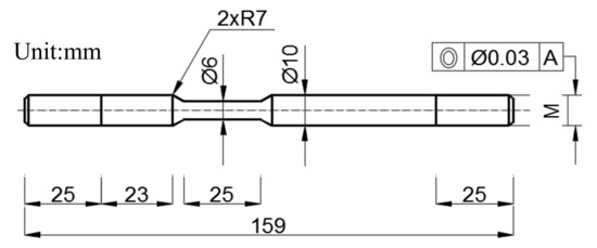
Figure 1.
Diagrammatic sketch of the slow strain rate tensile (SSRT) test sample with its dimension.
The samples were polished with 1000 grit waterproof abrasive paper, washed, and dried in turn. SSRT tests were employed on a RWS10 material tensile test machine (Changchun institute of mechanical science, Changchun, China) with a stretching rate of 10−6 mm·s−1 and a preload of 0.1 kN. The working area length of the sample is 25 mm, so the stretching rate set as mm/min in reality. To ensure the stability of the SSRT, the mechanical properties data were obtained from three samples.
The SSRT test was carried out in different environments: air, distilled water, 0.5 mol/L NaCl solution, and 0.5 mol/L Na2SO4 solution. These were all made by analytical reagent chemicals and distilled water.
To evaluate the SCC susceptibility of the alloys, the SCC susceptibility index (ISCC) was calculated based on ultimate tensile strength (UTS) and elongation to failure (ef) in solutions environment (S) and air as follows:
In order to analyze the SCC susceptibility of the alloy, the SCC susceptibility index (Iscc) equation based on ultimate tensile strength (UTS) and elongation at failure (ef) in the air and solution environment (S) was used as follows [19]:
where, S means solution (distilled water, NaCl aqueous solution, Na2SO4 aqueous solution) to distinguish the “Air”. IUTS and Ie were used to characterize the ISCC. The closer they got to 1.0, the greater the resistance against SCC.
2.3. Electrochemical Polarization Test
Corrosion open circuit potential curves were tested along with the SSRT test. The open circuit potential was recorded every 60 s. Tafel curves were measured in the NaCl and Na2SO4 aqueous solution with strengths of 0 and 100 MPa. Electrochemical polarization tests were carried out in the LK98B11 chemical workstation (Tianjin Lanlike chemical electronic high-tech Co. LTD, Tianjin, China). The exposed area was the working area, which was about φ 5.9 mm × 25 mm, and the other area was protected through coatings. We used a standard three electrode configuration in the Tafel curves: a saturated calomel as the reference electrode, a platinum electrode as the standard electrode, and the sample as the working electrode. The polarization scan was carried out under stress of 0 and 100 MPa at a rate of 10 mV/s in Tafel and the sensitivity of the open circuit potential was 1 μA. The increasing rate of stress was 10 MPa/min.
The experimental model and the actual experimental equipment are shown in the Figure 2.
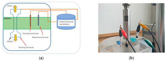
Figure 2.
Schematic diagram of electrochemical test method (a) and photo of the device (b).
2.4. Sample Preparation
Tests alloys were ground using silicon carbide sandpaper ranging from 300, 600, 1200, 1500, to 2000 grit with water as the lubricant. The samples used to observe the microstructure were corroded by 3.5% nitric acid ethyl alcohol for 30 s. The microstructure of the longitudinal section and vertical sections and fracture analysis were recorded by SEM equipment. The overall corrosion morphology was observed using a stereomicroscope.
The fracture and corroded surfaces were cleaned by pickling in a solution containing 200 g/L CrO3 at room temperature for 10 min.
3. Results
3.1. Microstructure
The radial section microstructure of the AM50Gd magnesium alloy is shown in Figure 3. Previous research [20] showed that after Gd added, the microstructure consisted of dark α-Mg, and the bright β-Mg17Al12, Al2Gd3, and Al–Mn–Gd phases. It can be seen that there was an obvious compressed flow of microstructure around as the β-Mg17Al12 phases were crushed into smaller particles. Furthermore, it was sandwiched between the dynamic recrystallization of α-Mg grains. However, no Gd-containing phases were observed as broken because they were harder than the β phases. The addition of gadolinium into the AM50 alloy led to a great improvement in the microstructure. The beneficial effects of RE elements on the corrosion behavior of Mg–Al alloys is mainly determined by three main factors [21]: (i) a reduction in the effect of impurities such as Cu, Fe, Ni, and O due to the formation of intermetallic compounds; (ii) the formation of Al–RE phases with low cathodic activity, which reduce the volume fraction of the β-Mg17Al12 intermetallic and, therefore, suppresses micro-galvanic couples; and (iii) the refinement of the quality of the corrosion films on the alloy surface in solution. Furthermore, substantial improvement in the corrosion resistance of magnesium alloys can be achieved through the addition of Gd. The refinement of the microstructure and formation of Al–Gd phases that are more stable than the β-Mg17Al12 phase can also result in improved mechanical properties at high temperatures.
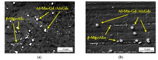
Figure 3.
SEM morphology of the AM50Gd magnesium alloy. Radial (a) and axial (b) sections.
Table 2 showed the UTS and Elongation of the as-cast and hot extrusion treated AM50Gd alloy. According to the authors’ previous researches [20,21], under gravity casting conditions, the corrosion resistance of AM50 magnesium alloy was improved after the addition of Gd, but the mechanical properties were not significantly improved. After hot extrusion processing, the maximum tensile strength of the alloy increased from 213 to 315 MPa, and its elongation increased from 2.75% to 8.1%. After the addition of rare earth Gd and the hot extrusion treatment, the mechanical properties of the new material such as tensile strength and elongation were significantly improved due to the second-phase strengthening and grain refinement.
Table 2.
The mechanical properties of the AM50Gd magnesium alloy.
3.2. Slow Strain Rate Tensile (SSRT) Test
The representative stress vs. elongation plots for the alloy at the strain rate of 1.0 × 10⁻⁶ mm/s under air, distilled water, NaCl, and Na2SO4 solution are shown in Figure 4, while the comparison of the ultimate tensile stress (UTS) and elongation to failure (ef) is illustrated in Figure 5a.
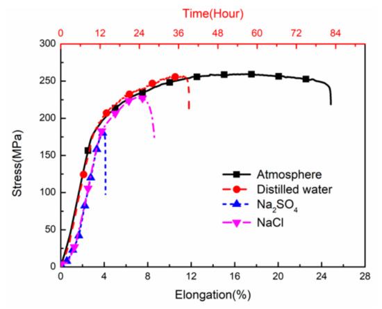
Figure 4.
The stress vs. elongation plots of AM50Gd magnesium alloy at a strain rate 1.0 × 10⁻⁶ under different environmental conditions.
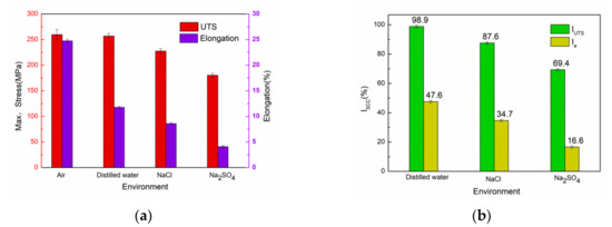
Figure 5.
Comparison of the SSRT data (a) and SCC susceptibility index (b).
The alloy tested in air exhibited a good combination of strength and ductility where the ef was 24.7(±0.3)% and UTS was 259 (±10) MPa. However, the alloy tested in distilled water showed a significant loss in the mechanical properties (ef = 11.78 ± 0.2% and UTS = 256 ± 5 MPa). The mechanical properties were further weakened in NaCl solution (ef = 8.6 ± 0.2% and UTS = 227.4 ± 5 MPa), and drastically dropped in Na2SO4 solution (ef = 4.1 ± 0.2% and UTS = 180.8 ± 4 MPa).
The comparisons of the SCC susceptibility index (Iscc calculated from UTS and ef) are shown in Figure 5b. Relative to the inert environment in the air, the Iscc tested in distilled water increased to 98.9%. Meanwhile the Ie was 47.6%. Furthermore, in NaCl solution, the Iscc reached 87.5%, and the Ie was 34.7%. In addition, the Iscc in the 0.5 mol/L Na2SO4 solution dropped to 69.4%, while Ie dropped to 16.6%. The results indicated that the Iscc of the samples in different environments was in the order of distilled water > NaCl > Na2SO4. The Ie results coincided with the Iscc, which indicates that the alloy is more prone to stress corrosion in 0.5 mol/L Na2SO4 solution.
The maximum fracture strength of the alloy in the SSRT in distilled water decreased slightly, but the elongation decreased more, to nearly half of that in air, indicating that the toughness of the material in pure water decreased significantly. Due to the slow tensile rate, the sample was in full contact with water. However, the corrosion effect of pure water was small, and the tensile curve of the sample was less different to that in air. With the increase of tension, the loose oxide film on the surface of the alloy began to crack, and microcracks formed on the surface of the alloy. The contact between water and fresh metal produced H, and H accumulated at the crack, leading to hydrogen embrittlement of the alloy. As the toughness of the alloy decreased, the fracture occurred quickly.
In the NaCl solution, due to the small size of the Cl− anions, they easily passed through the oxide film/hydroxide film on the surface of the alloy and acted on the matrix, which caused pitting nucleation on the matrix and the oxide film on the alloy surface was destroyed [22]. Stress concentration was formed at the bottom of the pitting where microcracks nucleated and expanded, resulting in the rapid fracture of the sample.
At the same concentration, sulfate ions have more effect on stress corrosion sensitivity than chloride ions. In the sodium sulfate solution, the number of corrosion pits on the surface of the sample was less than that in the sodium chloride solution. However, the corrosion pit in the Na2SO4 solution was obviously deeper. It caused the specimen to fracture rapidly in a shorter time. This form of corrosion was fatal, affecting far more than the formation of many scattered pits. Sulfate ions promoted the accumulation of H at the crack tips, leading to brittle fracture of hydride at the crack tip. With the increase of corrosion pit depth, local acidification was formed, which accelerated the corrosion and lead to the expansion of the corrosion pits toward the axis of the tensile rod [11].
3.3. Electrochemical Tests
The corrosion open circuit potential curves during SSRT in distilled water, NaCl, and Na2SO4 aqueous solutions are presented in Figure 6a. It can be seen that the value of the open circuit potential in distilled water was about −1.5 V, and decreased slowly with the SRRT process. The open-circuit potential in sodium chloride solution was about −1.6 V, and the value was basically stable. However, the corrosion potential in the sodium sulfate solution increased significantly, with the initial potential of about −1.65 V, and then increased to −1.55 V within 13 h.
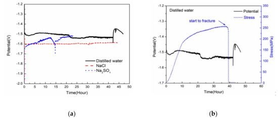
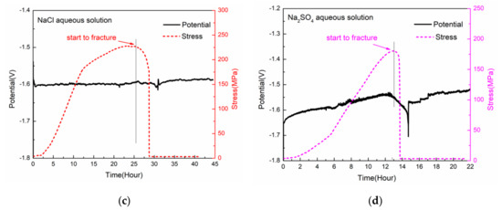
Figure 6.
The corrosion open circuit potential curves during SSRT in different aqueous solutions (a), the corrosion open circuit potential curve with SSRT curve in distilled water (b), the NaCl aqueous solution (c), and the Na2SO4 aqueous solution (d).
Figure 6b shows the slow drawing process of pure water and the in situ open-circuit potential diagram. It can be seen that in the slow drawing process, except for a small fluctuation where the potential first decreased and then increased within the first five hours, the potential trend on the whole decreased slowly until the sample broke. In the NaCl solution (Figure 6c), with increasing displacement, the open-circuit potential basically tended to be stable with little change. However, in the Na2SO4 solution (Figure 6d), with the progress of SSRT, the open-circuit potential increased at a relatively fast speed until fracture. All three open-circuit potential curves started at the maximum tensile stress and finally broke completely, and the potential showed a downward trend.
The stress corrosion of magnesium alloys is mainly caused by anodic dissolution and cathodic hydrogen evolution [23,24]. However, the stress corrosion properties of the alloy changed in different corrosive media. In distilled water, the stress corrosion cracking sensitivity of the alloy was not high due to the ISCC, but according to the Ie, the stress corrosion cracking sensitivity decreased more. Since there were no other ions in pure water, the corrosion form of the magnesium alloy was affected more by hydrogen evolution. Hydrogen generated by the cathodic reaction reached the crack tip under the action of stress, which reduced the binding energy between atoms at the crack tip and promotes the occurrence of dislocation. The crack tip slipped and new dislocation nucleation occurred, so there were many dimples in the fracture of the sample.
Under the tensile stress conditions of 0 MPa and 100 MPa, the Tafel curves were measured in the NaCl and Na2SO4 solutions, respectively, as shown in Figure 7. The corrosion current density and corrosion potential of the alloy were list in Table 3. As can be seen from Figure 7 and Table 3, under the tensile stress of 0 MPa and 0.5 mol/L NaCl solution, the corrosion potential was about −1.65 V, and the corrosion current density was 1.775 × 10⁻⁴ mA/cm2. When the stress was increased to 100 MPa, the potential slightly moved to the left to −1.67 V and the corrosion current density increased to 5.374 × 10⁻⁴ mA/cm2. In the Na2SO4 solution, the corrosion potential was −1.71 V at 0 MPa, and −1.72 V at 100 MPa. The corrosion current density increased from 2.718 × 10⁻⁴ to 5.432 × 10⁻⁴ mA/cm2. In general, in the presence of 100 MPa stress, the current density increased to three-fold in the sodium chloride solution, but only two-fold in the sodium sulfate solution. When the load was 0 MPa, the corrosion current density of sodium chloride solution was smaller than that of the sodium sulfate solution, indicating that the corrosion resistance of the material in sodium sulfate solution was poor under the same ion concentration. In the presence of stress, the current densities of the samples in the two solutions were similar. Both figures showed that the surface activity of the alloy increased and the corrosion resistance decreased under 100 MPa tensile stress. In the presence of stress, the corrosion product film on the surface of magnesium alloy cracked, so that the cracked part and the unbroken part constituted a phenomenon of a large cathode and a small anode. This phenomenon produced a large instantaneous corrosion current. At the same time, the stress was concentrated at the crack tip, resulting in no passivation at the crack tip, thus promoting anodic dissolution, thus, accelerating the corrosion. Therefore, in the presence of stress, the anode branch current of the Tafel curves increased.
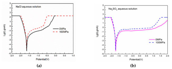
Figure 7.
Tafel curves under 0 and 100 MPa in NaCl (a) and Na2SO4 (b) aqueous solution.
Table 3.
The corrosion current density and corrosion potential of AM50Gd alloy tested under 0 and 100 Mpa in different solution environments.
3.4. Surface and Fracture Morphology
Figure 8 shows body microscope pictures of the samples in air, distilled water, NaCl, and Na2SO4 solution. It can be seen from Figure 8a that the surface of the slowly-drawn sample in the air had uniform deformation lines. Although the magnesium alloy was originally a brittle material, the fracture of the sample showed necking after extrusion processing and presented ductile fracture characteristics. Figure 8b shows the surface morphology of the SSRT specimen of the alloy in distilled water. It can be seen that there were many cracks on the surface of the specimen perpendicular to the tensile direction. Macroscopically, the fracture had a large slope, which was the result of a fracture along the direction of the crack propagation. The samples in NaCl solution (Figure 8c) had significantly fewer surface microcracks perpendicular to the tensile force, mainly due to the low tensile force at the time of fracture and the appearance of deep corrosion pits around the fracture. The appearance of corrosion pits was similar to that obtained by conventional immersion corrosion. In the Na2SO4 solution, the fracture of the SSRT sample was relatively flat, and a small number of cracks perpendicular to the fracture appeared on the sample. A large corrosion pit appeared near the fracture, and the corrosion pit ran through the sample to the fracture.
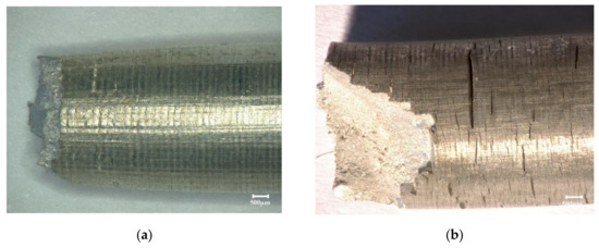
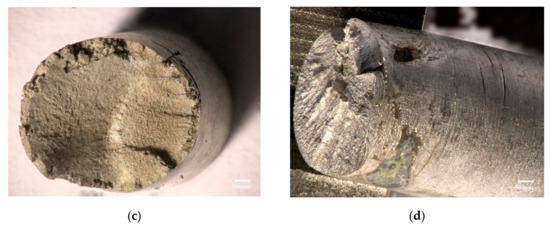
Figure 8.
The surface morphologies of the alloy in air (a), distilled water (b), NaCl (c), and Na2SO4 (d) aqueous solutions.
Figure 9 is the SEM image of the fracture of the SSRT specimen in air. Figure 9a shows the overall morphology, while Figure 9b shows the partial enlarged morphology. It can be seen that there were many dimples in the fracture. In addition, there were some cleavage steps, indicating that the chronic tensile fracture of the material had mixed characteristics of ductile fracture and cleavage fracture. The fracture mechanism of the alloy changed from a brittle fracture to a ductile fracture. However, the toughness characteristics were more obvious, as can be seen from the data in Figure 4. Figure 9d shows the EDS results of point scanning at point A in Figure 9c. The composition of the particles contained the elements Al, Mn, and Gd, indicating that the composition was rare earth contained phase.
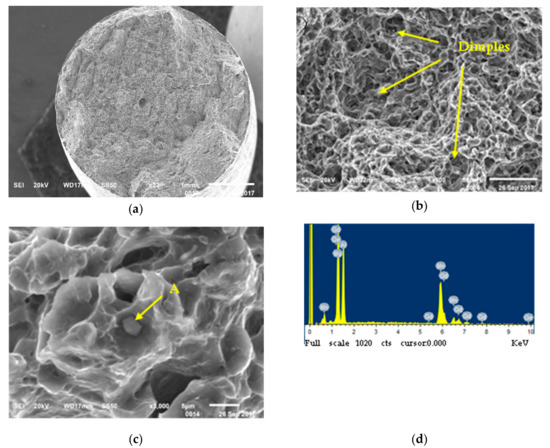
Figure 9.
Fractographies of the SSRT test sample in air: (a) ×23, (b) ×500, (c) ×3000, and (d) EDS results of Point A.
Figure 10 shows the SEM fracture morphologies of the SSRT sample in distilled water. The fracture was divided into two parts: the middle part was similar to the fracture in air, and the edge of the sample was about 0.5 mm wide in the area affected by water. Corrosion products and microcracks appeared in the fracture of the corrosion area (Figure 10a), and some corrosion pits appeared at the edge of the corrosion area (Figure 10b). These pits were shallow and basically parallel to the edge.
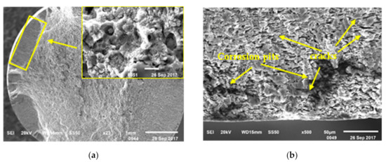
Figure 10.
Fractographies of the SSRT test sample in distilled water. (a) Overall, (b) edge.
Figure 11 illustrated the fracture morphology of the SSRT specimens in NaCl solution. The sample was basically divided into two zones: the corrosive action zone and the internal zone (Figure 11a). The surface of the sample showed typical corrosion characteristics of Cl− containing solution, i.e., pitting corrosion. The corrosion pits were superimposed and interwoven with each other, and the corrosion pits went into the sample longitudinally, with an average depth of about 0.7 mm, which was larger than that in pure water. The corrosion inside the pit was severe, the α-Mg phase basically disappeared, and only the skeleton of the β-phase remained. In addition, the microcracks gathered at the bottom of the pit, forming a stress concentration. With the stress loading, the crack expanded, which directly led to the fracture failure of the sample (Figure 11c). In Figure 11b,d, large tearing edges appeared in the fracture, and the crystal surface was corroded, but the corrosion was incomplete, indicating that there was a short contact time between the corrosive liquid and the internal structure. At this time, the specimen was a brittle fracture, and the elongation and maximum tensile strength were significantly reduced. The fracture was caused by the action of anodic dissolution and hydrogen embrittlement [25]. The parallel sections produced by hydrogen cracking can be seen in the image. Quasi-cleavage fracture features reappeared [26].
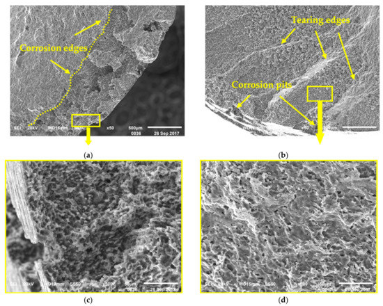
Figure 11.
Fractographies of the SSRT test sample in 0.5 mol/L NaCl aqueous solution (a). (b) Overall, (c) Corrosion field, and (d) Field without corrosion.
Figure 12 shows the fracture morphologies in the Na2SO4 solution. It can be seen that there were large corrosion holes and microcracks in the sample center. However, unlike the samples in NaCl and pure water, the partition at the fracture of the sample was not obvious. The specimen presented the characteristics of a brittle fracture. The crack rapidly expanded in the corrosion hole, leading to the rapid fracture of the specimen. Therefore, the fracture was less affected by the corrosive liquid.
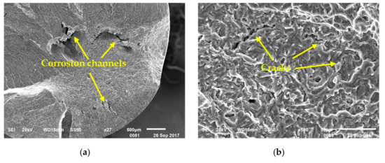
Figure 12.
Fractographies of the SSRT test sample in 0.5 mol/L Na2SO4 aqueous solution. (a) Overall, (b) Field in the middle.
In the NaCl and Na2SO4 solutions, in addition to the influence of hydrogen on the brittle fracture of samples, they were also affected by other mechanisms of anodic dissolution. Crack sources were widely found at the bottom of the newly formed pits, and the fracture failure of the material was accelerated due to the effect of stress concentration. Therefore, the fracture strength and elongation of the materials were significantly reduced. Especially in the sodium sulfate solution, although the number of corrosion pits was not large, under the influence of the hydrogen embrittlement delayed fracture mechanism, the hydride under stress caused a brittle fracture, where the crack continued to expand in the axial direction, and the effect occurred repeatedly, producing the sample fracture at the fastest speed. Therefore, the stress corrosion sensitivity of the sample was the highest.
4. Conclusions
A comparative study of stress corrosion behavior of AM50Gd alloy in air, distilled water, NaCl and Na2SO4 solutions has been made. The main conclusions are:
- 1)
- The stress corrosion sensitivity of the material in different environments was Na2SO4 > NaCl > distilled water > air, respectively.
- 2)
- According to the Tafel curves measured at 0 and 100 MPa, the corrosion voltage decreased little and the corrosion current density increased rapidly under 100 Pa. This was because the film of the corrosion product ruptured to form a large cathode and a small anode, which resulted in a large instantaneous corrosion current.
- 3)
- The mechanism of hydrogen embrittlement and anodic dissolution together affected the stress corrosion behavior of the alloy. In distilled water, hydrogen embrittlement played a major role, while in NaCl and Na2SO4 solution hydrogen embrittlement and anodic dissolution were both affected.
- 4)
- The direct reason of the SCC sample failure was the cracks expanding rapidly at the bottom of pit, which was caused by corrosion.
Author Contributions
Conceptualization, M.Y. and Y.S.; methodology, M.Y.; validation, M.Y., X.L. and Z.Z.; formal analysis, Z.Z.; investigation, M.Y.; resources, X.L., Z.Z.; data curation, M.Y.; writing—original draft preparation, M.Y.; writing—review and editing, M.Y.; visualization, X.L.; supervision, Z.Z.; project administration, X.L.; funding acquisition, X.L.
Funding
This research was funded by National Natural Science Foundation Regional Science Foundation Project (No. 51564005); the Jilin Science and Technology Innovation Development Plan Project (No. 201750247, 201750225); and the Science and Technology Research Project of Education Department of Jilin Province (JJKH20180335KJ).
Acknowledgments
I would like to thank Qiang Wang from Institute of metal research, Chinese academy of sciences for his help in the fracture detection of the sample. I would also like to thank Hongde Fu and Zhen Wang from Jilin University for discussing the details of the experiment with me.
Conflicts of Interest
The authors declare that there is no conflict of interests regarding the publication of this article.
References
- Wang, Q.; Liu, Y.; Fang, S.; Song, Y.; Zhang, D.; Zhang, L.; Li, C. Evaluating the improvement of corrosion residual strength by adding 1.0 wt.% yttrium into an AZ91D magnesium alloy. Mater. Charact. 2010, 61, 674–682. [Google Scholar] [CrossRef]
- Zhang, T.; Meng, G.Z.; Shao, Y.W.; Cui, Z.Y.; Wang, F.H. Corrosion of hot extrusion AZ91 magnesium alloy. Part II: Effect of rare earth element neodymium (Nd) on the corrosion behavior of extruded alloy. Corros. Sci. 2011, 53, 2934–2942. [Google Scholar] [CrossRef]
- Yang, M.; Liu, Y.H.; Liu, J.A.; Song, Y.L. Effect of T6 heat treatment on corrosion resistance and mechanical properties of AM50 magnesium alloy. Mater. Res. Innova. 2016, 19, 259–264. [Google Scholar] [CrossRef]
- Yin, Z.; Liu, F.; Song, D.; He, S.; Lin, J.; Yu, F. Stress corrosion cracking of a forged Mg-Al-Zn alloy with different surface conditions. J. Chem. 2018, 2018. [Google Scholar] [CrossRef]
- Klein, M.; Frieling, G.; Walther, F. Corrosion fatigue assessment of creep-resistant magnesium alloys DieMag422 and AE42. Eng. Fract. Mech. 2017, 185, 33–45. [Google Scholar]
- Esmaily, M.; Svensson, J.; Fajardo, S.; Birbilis, N.; Frankel, G.; Virtanen, S.; Arrabal, R.; Thomas, S.; Johansson, L. Fundamentals and advances in magnesium alloy corrosion. Prog. Mater. Sci. 2017, 89, 92–193. [Google Scholar] [CrossRef]
- Song, Y.; Shan, D.; Han, E.H. Pitting corrosion of a rare earth Mg alloy GW93. J. Mater. Sci. Technol. 2017, 33, 954–960. [Google Scholar] [CrossRef]
- Song, G.; Bowles, A.L.; Stjohn, D.H. Corrosion resistance of aged die cast magnesium alloy AZ91D. Mat. Sci. Eng. A 2004, 366, 74–86. [Google Scholar] [CrossRef]
- Jafari, S.; Raman, R.S.; Davies, C.H.; Hofstetter, J.; Uggowitzer, P.J.; Löffler, J.F. Stress corrosion cracking and corrosion fatigue characterisation of MgZn1Ca0. 3 (ZX10) in a simulated physiological environment. J. Mech. Behav Biomed. 2017, 65, 634–643. [Google Scholar] [CrossRef] [PubMed]
- Song, R.G.; Blawert, C.; Dietzel, W.; Atrens, A. A study on stress corrosion cracking and hydrogen embrittlement of AZ31 magnesium alloy. Mater. Sci. Eng. A 2005, 399, 308–317. [Google Scholar] [CrossRef]
- Winzer, N.; Atrens, A.; Dietzel, W.; Raja, V.; Song, G.; Kainer, K. Characterisation of stress corrosion cracking (SCC) of Mg–Al alloys. Mater. Sci. Eng. A 2008, 488, 339–351. [Google Scholar] [CrossRef]
- Padekar, B.S.; Raja, V.S.; Raman, R.K.S.; Lyon, P. Stress corrosion cracking behavior of magnesium alloys EV31A and AZ91E. Mater. Sci. Eng. A 2013, 583, 169–176. [Google Scholar] [CrossRef]
- Padekar, B.S.; Raja, V.S.; Raman, R.K.; Paul, L. Stress corrosion cracking of a new rare- earth containing magnesium alloy, Elektron21 compared with AZ91E. Mater. Sci. Forum 2011, 690, 361–364. [Google Scholar] [CrossRef]
- Mirzadeh, H. Quantification of the strengthening effect of rare earth elements during hot deformation of Mg-Gd-Y-Zr magnesium alloy. J. Mater. Res. Technol. 2016, 5, 1–4. [Google Scholar] [CrossRef]
- Huang, Y.; Gan, W.; Kainer, K.U.; Hort, N. Role of multi-microalloying by rare earth elements in ductilization of magnesium alloys. J. Magnesium Alloys 2014, 2, 1–7. [Google Scholar] [CrossRef]
- Rosalbino, F.; Angelini, E.; De Negri, S.; Saccone, A.; Delfino, S. Effect of erbium addition on the corrosion behaviour of Mg–Al alloys. Intermetallics 2005, 13, 55–60. [Google Scholar] [CrossRef]
- Yang, M.; Zhang, Z.; Liu, Y.; Han, X. Corrosion and mechanical properties of AM50 magnesium alloy after modified by different amounts of rare earth element Gadolinium. Open Phy. 2016, 14, 444–451. [Google Scholar] [CrossRef]
- Cao, F.; Shi, Z.; Song, G.L.; Liu, M.; Dargusch, M.S.; Atrens, A. Stress corrosion cracking of several hot-rolled binary Mg–X alloys. Corro. Sci. 2015, 98, 6–19. [Google Scholar] [CrossRef]
- Song, Y.; Wang, Z.; Liu, Y.; Yang, M.; Qu, Q. Influence of Erbium, Cerium on the stress corrosion cracking behavior of AZ91 alloy in humid atmosphere. Adv. Eng. Mater. 2017, 19, 1700021. [Google Scholar] [CrossRef]
- Yang, M.; Liu, Y.; Liu, J.; Song, Y. Corrosion and mechanical properties of AM50 magnesium alloy after being modified by 1 wt.% rare earth element gadolinium. J. Rare Earths 2014, 32, 558–563. [Google Scholar] [CrossRef]
- Yang, M.; Zhang, Z.; Han, X.; Liu, Y. Corrosion mechanical properties of hot extrusion treated AM50GdX magnesium alloy. J. Chin. Soc. Rare Earths 2016, 34, 425–431. [Google Scholar]
- Atren, A.; Song, G.L.; Liu, M.; Shi, Z.; Cao, F.; Dargusch, M.S. Review of recent developments in the field of magnesium corrosion. Adv. Eng. Mater. 2015, 17, 400–453. [Google Scholar] [CrossRef]
- Zhou, L.; Liu, Z.; Wu, W.; Li, X.; Du, C.; Jiang, B. Stress corrosion cracking behavior of ZK60 magnesium alloy under different conditions. Inter. J. Hydrogen Energ. 2017, 42, 26162–26174. [Google Scholar] [CrossRef]
- Xie, Q.; Ma, A.; Jiang, J.; Cheng, Z.; Song, D.; Yuan, Y.; Liu, H. Stress corrosion cracking behavior of fine-grained AZ61 magnesium alloys processed by equal-channel angular pressing. Metals 2017, 7, 343. [Google Scholar] [CrossRef]
- Padekar, B.S.; Raman, R.S.; Raja, V.S.; Paul, L. Stress corrosion cracking of a recent rare-earth containing magnesium alloy, EV31A, and a common Al-containing alloy, AZ91E. Corro. Sci. 2013, 71, 1–9. [Google Scholar] [CrossRef]
- Kannan, M.B.; Dietzel, W. Pitting-induced hydrogen embrittlement of magnesium–aluminium alloy. Mater. Des. 2012, 42, 321–326. [Google Scholar] [CrossRef]


© 2019 by the authors. Licensee MDPI, Basel, Switzerland. This article is an open access article distributed under the terms and conditions of the Creative Commons Attribution (CC BY) license (http://creativecommons.org/licenses/by/4.0/).