Article

Simulation and Experimental Investigation of Granular Medium Forming Technology on Titanium Alloy Sheet at 500 °C

1
Faculty of Mechanical Engineering & Automation, Zhejiang Sci-Tech University, Hangzhou 310018, China
2
Key Laboratory of Advanced Manufacturing Technology of Zhejiang Province, School of Mechanical Engineering, Zhejiang University, Hangzhou 310027, China
3
School of Mechanical Engineering and Automation, Beihang University, Beijing 100191, China
*
Author to whom correspondence should be addressed.
Metals 2021, 11(1), 114; https://doi.org/10.3390/met11010114
Submission received: 12 December 2020 / Revised: 30 December 2020 / Accepted: 5 January 2021 / Published: 8 January 2021
(This article belongs to the Special Issue Lightweight Alloys for Aerospace Applications)

Abstract

:
To investigate and verify the degree to which the forming properties of low plasticity materials are improved at room temperature using the granular medium forming (GMF) process at 500 °C, a coupled Eulerian–Lagrangian unit calculation model was established and a special mold was designed to conduct a GMF experiment for titanium alloy sheets under different-shaped pressing blocks. Then, using a three-coordinate measuring machine, the sizes of the outer contours of the parts formed at room temperature were measured, and the results showed that the bottom of the parts maintained a smooth surface during the drawing process. As the drawing height increased, the radius of curvature of the cambered surface gradually decreased. By measuring the wall thickness of the parts at different positions from the central axis using a caliper, the wall thickness distribution curves of these parts were obtained, which showed that the deformations of the bottom of the formed parts were uniform and the uniformity of the wall thickness distribution was good. By comparing the GMF experimental data at 500 °C with traditional deep drawing experimental data, it was found that the GMF technology could improve the forming properties of low plastic materials such as titanium alloys.

1. Introduction

The granular medium forming (GMF) process, which uses solid granules as a pressure-transfer medium in order to form a workpiece, is a newly proposed flexible die-forming technique [1,2,3,4]. Because the application of this process can fully exploit recent advances in the formability of lightweight materials at elevated temperatures, as well as overcome the limitations that the heat-resistant oil used in warm hydroforming operations can withstand temperatures of no more than 350 °C [5,6,7] and that the inert gas used at higher temperatures in hot pneumatic bulging processes usually causes leakage problems [8,9], the GMF process has recently attracted considerable attention by several researchers [10,11,12].
GMF is applied mainly in the fabrication of thin-walled lightweight components such as titanium alloys and high-strength steel parts at relatively high temperatures (above 500 °C) [13,14,15]. In our previous studies [4,16], the flow model of granular mediums and the viscoplastic unified constitutive model of titanium alloy sheets at high temperatures were both analyzed, and the relationships governing the mechanical responses of bodies under deformation during the forming process of granular mediums at high temperatures, including those discussed in other studies [17,18,19], were determined. Based on this research, the finite element analysis (FEA) method was used to simulate the GMF process of a titanium alloy sheet [4]. To evaluate the accuracy of the model and verify the forming properties of low plastic materials at room temperature (RT), an experimental investigation of the GMF process on a titanium alloy sheet at 500 °C was carried out. A free deep drawing experiment on titanium alloy sheets under different conditions was conducted using a self-designed mold, and the feasibility of using GMF at elevated temperatures to fabricate complex thin-walled parts was initially shown to be viable. As this study presents a new and precise forming manufacturing approach, it is important to carry out further studies of the forming method for complex thin-walled parts at elevated temperatures [20,21,22].

2. Coupled Eulerian–Lagrangian Simulation and Analysis of the GMF Process

2.1. Coupled Eulerian–Lagrangian Simulation Modeling

At present, a large number of Lagrangian element description methods have been used to analyze the results of sheet forming simulation [23,24], as these descriptions can more accurately capture the external boundary information of a sheet during the deformation process and realize the complex contact calculation between a sheet blank and mold. For the GMF process, if a traditional Lagrangian element is used, the granular medium mesh will often be severely distorted during deformation, which greatly reduces the calculation accuracy, even to the point of not converging [4]. In fact, the granular medium shows characteristics more like a fluid medium in the forming process, making it is more suitable for description using Eulerian units. Arienti et al. [25] also pointed out that quite a few analytical problems encountered in the engineering field cannot be solely described by the Eulerian or Lagrangian method, but they can be described by a combination of the two. Fortunately, the Abaqus FEA (https://www.4realsim.com/abaqus) software provides two element description forms of the Lagrangian and Eulerian elements [10], and these two element calculation models can be included in the same calculation example to analyze coupling effects, such as contact friction between the two models [26]. Additionally, when the two element calculation models are deformed, the Eulerian element nodes are fixed in three-dimensional space. Therefore, no matter to what degree the calculation model is deformed, the element will always maintain its original shape and will not produce numerical calculation errors caused by grid distortion. To avoid the undesirable mesh distortion of the traditional Lagrangian element during the numerical simulation, a coupled Eulerian–Lagrangian (CEL) method of analysis [4] was adopted in order to characterize the mechanical behavior of the granular material using CEL-based simulation.
Using the Abaqus FEA software, the CEL element calculation model was constructed, as shown in Figure 1. According to the size of the GMF experimental mold described in our previous study [4], the corresponding plane element rigid models of the charging barrel, inlaid die, and punch lock block were employed. The forming blank was described by the four-node S4R Lagrangian element with reduced integration, and the granular medium was represented by the three-dimensional eight-node Eulerian element EC3D8R. Considering that the calculation model was symmetric about the y-axis, a quarter of the calculation model was defined in order to carry out the calculation.
As mentioned above, when the Euler method is used to describe the motion of an entity, the coordinates of the nodes in the space are used as the calculation basis. The material can move and deform to any degree in the three-dimensional space. Therefore, in order to have a complete description of the material flow state, the corresponding Eulerian grids must be established for all possible areas of the granular medium. Since the Eulerian element nodes do not flow with the material, it is necessary to first calculate the outer boundary of the Eulerian body and establish friction pairs between the Eulerian body and other entities in each analysis step so as to calculate the contact behavior between the models. In a study by Chen et al. [12], who compared the normal pressure with a coefficient of friction of 0.42 and a coefficient of friction of 0.23, it was found that high friction led to a higher pressure loss, so the coefficient of friction between the Lagrangian body and the Eulerian body was set to 0.23. In the Abaqus FEA software, the Eulerian volume fraction (EVF) can be used to characterize the internal material filling of the Eulerian unit. When the Eulerian mesh is completely filled with solid material, the EVF is 1, and when the Eulerian mesh is completely empty, the EVF is 0.

2.2. Calculation Results and Deformation Analysis of the CEL Algorithm at Room Temperature

Using the CEL algorithm, a simulation analysis of the GMF process at RT was carried out [4]. For the calculation, a flat-bottomed punch lock block was used, and the charging height, blank diameter, and die size were the same as those in the experiment. The deformation of the granular medium under different deep drawing heights of the parts was calculated using the Mohr–Coulomb model shown in Figure 2, which shows that the CEL algorithm could simulate the deformation and flow process of the granular medium and the sheet metal, and it could reflect the interaction between the granular medium and the blank. During the downward process of the lock block, the granular medium continuously squeezed the blank to deform it, and the bottom of the blank became a cambered surface during the middle stage of drawing. As the drawing height increased, the curvature of the cambered surface also gradually increased and finally fitted with the concave surface of the mold, which was consistent with the phenomenon obtained in the GMF experiment [4]. In addition, it was shown that during the entire forming process, no matter how much deformation the granular medium entity underwent, the Eulerian element meshes were still regularly distributed in the three-dimensional space without any mesh deformation, which means that the calculation accuracy of the algorithm could be improved.

3. Experimental Investigation of the GMF Process

3.1. Mold Design for the GMF Process

The mold needed for titanium alloy sheet forming at high temperatures is different from that needed at RT conditions. It requires a simple and reliable structure that prevents thermal stress, or even thermal destruction, that can occur due to the temperature gradient existing inside the die. As the die needs to work under high-temperature conditions for long periods and part of the mold structure is subjected to intense pressures, so the selected mold materials must possess high-temperature strength and good oxidation resistance. In addition, the choice of lubrication between the mold and the blank is a major consideration.
In accordance with this study’s requirements for the GMF test of the titanium alloy at elevated temperatures, the specially designed mold forming tooling and objects shown in Figure 3 were used. The mold tooling was composed of a heat insulation plate, an all-round die holder, an inlaid die, a charging barrel, a punch pillar, and a punch lock block. The upper surface of the all-round die holder was processed with a heating wire slot having a width of 27 mm and a depth of 50 mm in which the nickel–chromium alloy heating wire was inserted. The heat insulation plate was made of a high-temperature ceramic material in order to reduce heat conduction and forming pressure. The inlaid die was placed in the all-round die holder, which could be replaced according to the different fabricated parts in order to reduce the manufacturing cost of the mold. The punch lock block, which was fixed to the bottom of the punch pillar by a high temperature-resistant inner hexagon bolt, could move along the main cylinder beam. An enclosed space was formed by the charging barrel, the blank, and the punch lock block to store the granular medium, and the lower surface of the charging barrel contacted the blank in order to hold the blank.
In order to study the effect of different shapes of lock blocks on the pressure transmission performance of the granular medium, three differently shaped punch lock blocks were designed and tested in this study, as shown in Figure 4. The bottom of punch lock block a was flat, and the bottoms of punch lock blocks b and c had a conical frustum and cylindrical embossing, respectively. According to the particle size characteristics of the selected granular medium (diameter Φ = 1 mm), in order to ensure adequate sealing between the test mold and the granular medium, as well as to allow the punch lock block to freely slide in the charging barrel, the clearance between the charging barrel and the punch lock block was designed to be less than 0.5 mm (δ < 0.5 mm). A parabolic part, which is commonly used in the aerospace industry, was selected as the part for verifying the GMF process. This verification part had a height of 55 mm, had a wide mouth diameter of 90 mm, and, if manufactured directly by the conventional deep drawing process, is prone to wrinkling.
The hot forming temperature of titanium alloys is relatively high (550–850 °C), and silicon–molybdenum cast iron was selected as the mold material for this experiment. Medium silicon–molybdenum cast iron, which has good high-temperature strength, oxidation resistance, and thermal stability, has been widely used in the high-temperature forming of molds. Adding a certain amount of molybdenum to the medium silicon ductile iron has the effect of strengthening a solid solution, and it can significantly improve the high-temperature properties of ductile cast iron, such as thermal shock resistance and creep resistance. Colloidal graphite in water was used as the lubricating agent between the blank and the mold. Before use, the graphite lubricant was first applied to the upper and lower surfaces of the sheet and then allowed to dry. The main component of the lubricant was finely pulverized graphite, which has good lubricity and high-temperature resistance. The lubricant covering the surface of the sheet material also played an anti-oxidative role.

3.2. Experimental Equipment and Setup

The GMF experiment was carried out at 500 °C using a YRJ-50 deep drawing testing machine produced by Foshan Kangsida Hydraulic Machinery Co. LTD (No. 66 Guxin Road, Chancheng District, Foshan city, Guangdong Province, China). The frame of the machine was composed of a main cylinder, a main cylinder beam, a blank holder cylinder, and a work surface, as shown in Figure 5. The blank holder cylinder was fixed on the main cylinder beam and moved with the main cylinder. When forming parts, the blank holder cylinder first contacted the charging barrel in the test mold and provided sufficient force to the blank holder while the main cylinder simultaneously continued to move down to push the lock block and extrude the granular medium to form the part. The maximum pressure of the main cylinder in the test equipment was 50 tons, and the effective size of the work surface was 480 mm × 480 mm, which met the needs of most forming tests.
In order to improve the heating efficiency, a suitable method for heating the mold, in which a nickel–chromium alloy heating wire embedded in the universal die socket was used to heat both the mold and the sheet, was adopted for this experiment. The surface of the heating wire was tightly sheathed in an insulating ceramic ring to prevent the heating wire contacting the internal surface of the mold. A temperature-measuring device used an armored thermocouple, which extended into the heating trough in order to measure the temperature of the mold. The temperature control system adopted a proportional–integral–derivative (PID) controller and used a set of step-down transformers to increase the current intensity in the heating element. A schematic diagram of the insulation and heating system used in this experiment is shown in Figure 6. During the test, a heat preservation furnace shell was placed outside the forming mold (Figure 6), though the shell played no other role. The gap between the furnace shell and the mold was filled with ceramic fiber cotton, which further reduced heat dissipation during the mold heating process.

3.3. Experimental Results and Analysis

3.3.1. GMF Experiment of Titanium Alloy Sheet at Room Temperature

A titanium alloy TA1 sheet with a diameter of 170 mm and a thickness of 1.0 mm was selected to carry out a GMF test on a parabolic part at RT. During the test, the blank holder gap was 1.1 times the material thickness, and the ceramic particle medium charging height was 60 mm. The punch lock block a with the flat bottom shown in Figure 4 was used, and the graphite lubrication method was employed. The parts formed under different deep drawing heights (H) are shown in Figure 7, which shows that the bottom of the part formed by the GMF process had a domed structure, similar to a hemispherical surface, and had a good external surface quality.
In contrast, it should be pointed out that defects such as wrinkling are prone to occur when using traditional deep drawing processes to manufacture parts with such spherical surfaces. Figure 8 shows the force diagram for the conical parts formed by the conventional deep drawing and GMF processes. When the conventional deep drawing process is employed, a force-bearing dangling area appears in the sheet during the drawing process (which is called the wrinkling danger zone), with no support on either side of the sheet in the normal direction, and the material element body is stretched in the radial direction and compressed in the circumferential direction. Figure 9 shows a picture of the severely wrinkled 2024-O aluminum alloy cone fairing formed by the conventional deep drawing process, with the thickness of the alloy sheet being 0.5 mm. Figure 9 shows that when the deep drawing height was lower and the blank at the flange had not completely flowed into the die, severe wrinkling appeared in the suspended area near the die corner of the part, which means that it is impossible to achieve high-quality tapered parts with single-pass forming using the conventional deep drawing process.
When a solid particle medium with fluidity is used instead of a rigid punch to form the parts during the blank deformation, the flexible punch continuously changes the contour of the bottom, which results in the deformation of the material and ensures that the sheet is subjected to beneficial normal stress in the thickness direction. At the same time, the micro-element body of the material in the deformation zone of the parts is in a biaxial tensile stress state, which can greatly reduce the wrinkling tendency and improve the formability. In addition, different from the active bulging process used in hydroforming technology, there is no need to completely press and seal the blank at the flange during the GMF process, which means that, under the condition of a proper blank holder gap, the blank at the flange can flow freely to the die and thus further improve the forming performance of the process for thin-walled parts.
During the GMF process, a large number of granules are extruded from one side surface of the blank to form an equivalent drawing force, which effectively avoids the difficult sealing problems in the forming process, such as liquid filling and air expansion. However, the granules used in the test were hard particles with a certain macro-size, which had a negative impact on the surface quality of the blanks in contact with them. In order to improve the quality of the internal surface of the parts formed by GMF, a preliminary study on the cushion materials between the sheet and granules was conducted. The surface quality of the parts formed by the GMF process was improved by using copper foil, and this was verified by laying down different thicknesses of copper foil between the forming sheets and the granular medium.
Figure 10 shows the internal surfaces of the parts formed under the same drawing height of 48.0 mm while using copper foil with thicknesses of 0.2 and 0.1 mm. Compared with the surface quality using copper foil with a thickness of 0.1 mm, that of the bottom center area of the part using the 0.2 mm copper foil was improved to a certain extent, but there were still a large number of pits of varying depths in the die corner areas. Figure 11 shows the form of the 0.1 mm copper foil after the GMF process, which shows that, due to poor plasticity, the copper foil was severely damaged at the die corner areas, where the deformation and friction were most severe. Therefore, the use of copper foil is unable to fully protect all of the deformation areas on the internal surface of parts formed by GMF. During the forming process, it is advisable to use sheets with greater elongation and thickness as the cushion material.
In order to evaluate the accuracy of the simulation calculation of the GMF process in the previous study [4], a three-coordinate instrument was used to measure the outer contour size of the granular medium-formed part at RT conditions, as shown in Figure 7, which yielded the outer contour of the formed granular medium shown in Figure 12a. This shows that during the forming process, the bottom of the part always maintained a smooth, cambered surface. As the drawing height continued to increase, the radius of curvature of the bottom cambered surface of the part gradually decreased.
Using wire cutters to cut the formed part along the central plane of symmetry and a caliper to measure the wall thickness at different positions from the central axis at the bottom of the part, the distribution of wall thickness curves was obtained, as shown in Figure 12b. The figure shows that the bottom of the formed parts had uniform deformations, and the conformity of the wall thickness distribution was good. Using an easy-flowing granular medium instead of a rigid punch was found to eliminate, to a large degree, the serious thinning of the blank that is likely to occur at the punch corners where force is concentrated. In addition, Figure 12b shows that the parts formed by the active GMF process had two minimum wall thickness points (shown by the circle in Figure 12b), one of which was located at the bottom center of the part, where the material was subjected to biaxial tensile stress and belonged to a greater deformation area. The other point was located near the cavity of the die, where the material was subjected to a two-way extrusion pressure between the granular medium and the forming die, which led to greater frictional resistance, thereby increasing the difficulty of material flows and resulting in a greater amount of material thinning.

3.3.2. Evaluation of the Calculation Accuracy of the CEL Algorithm at RT

Liu et al. [4] introduced and modified three geotechnical models, Mohr–Coulomb, Drucker–Prager, and Duncan–Chang, to study the granular medium sheet forming process. The Mohr–Coulomb model is an elastic–plastic deformation model widely used in geotechnical materials. The Drucker–Prager model corrects the Mohr–Coulomb yield function and eliminates the singularity caused by sharp angles. The Duncan–Chang model is a non-linear elastic model that is widely used in the field of geotechnical engineering. In order to evaluate the accuracy of the geotechnical model built in the previous study, three different material models were used to simulate the granular medium forming process. Curves comparing the profile dimensions of the part and the measured value of the real part at drawing heights (bottom of the part) of 28 and 48 mm, respectively, were obtained (Figure 13). This showed that when the stroke of the lock block was 28 mm, the Duncan–Chang nonlinear elastic model had the best prediction accuracy, while the calculated results of the Mohr–Coulomb model deviated somewhat from the true value. When the stroke of the lock block was 48 mm, the profile dimensions calculated by the three different models were close to the experimentally measured values.
The wall thickness distributions calculated by the three material models are shown in Figure 14, which shows that using granular media instead of rigid punches to form the parts could significantly reduce the serious thinning of the blanks at the punch corners and, as a consequence, further improve the forming limit. The wall thickness distribution curves calculated by the three different models along the nodes for drawing heights of 28 and 48 mm are shown in Figure 15. This shows that for a drawing height of 28 mm, these three models could more accurately predict the thickness distribution of the sheet metal, and the positions of the two minimum wall thickness points appearing at the bottom center and near the die corners were calculated. For a drawing height of 48 mm, the calculated results of the three models deviated somewhat from the experimentally measured value, with the Duncan–Chang model being the closest. The average percentage errors of the central wall thickness at the bottom of the parts, as calculated by the Mohr–Coulomb, Drucker–Prager, and Duncan–Chang models, were 7.54%, 8.21%, and 5.33%, respectively.

3.3.3. GMF Experiment on TA1 Sheet at 500 °C

Using the GMF test device described above, the TA1 sheet was tested at 500 °C. The blank diameter was 170 mm, the blank holder gap was still 1.1 times the thickness of the material sheet, and the granular medium charging height was 60 mm. In addition, in order to study the effect of different lock block shapes on the pressure transmission performance of the granular medium, three types of punch lock blocks—a, b, and c (shown in Figure 4)—were used, and the parts formed under 40 tons of equipment main cylinder pressure were obtained, as shown in Figure 16. This shows that the surface of the formed parts were smooth and without wrinkling. Under the pressure of the master cylinder, the forming heights of the parts using the three punch lock blocks a, b, and c were 50.0, 52.6, and 55.1 mm, respectively, which shows that the shape of the bottom of the punch lock block did have a definite effect on the forming performance of the granular medium. It also shows that the pressure distribution of the granular medium could be improved by selecting a punch lock block with a convex structure, which could enhance the effective force applied to the deformation area of the sheet. In addition, Figure 16 shows that, as the water-based graphite lubricant used in this study was a better lubricant for the blank and the mold at high temperatures, the surface quality of the formed parts was still good in the areas where they contacted the die corner.
Figure 17 shows the profile curves and wall thickness distribution curves of the central symmetry surface of the parts formed at 500 °C. Figure 17a shows that, similar to the parts formed at RT, the bottom contour of the parts formed at 500 °C was still a circular arc surface. With the increasing drawing depth, the curvature of the bottom contour of the parts continued to increase until it fitted with the die surface. From the bottom wall thickness distribution curves of the parts shown in Figure 17b, it can be seen that the minimum wall thicknesses at the bottom center of the parts formed by punch lock blocks a, b, and c were 0.90, 0.88, and 0.88 mm, respectively. Combined with the variation in the contour curve during the part-forming process shown in Figure 17a, the deformation characteristics of the blank in the GMF process described in the previous study [4] were further verified. Unlike the active hydroforming or gas bulging forming processes, the blank deformation was achieved by thinning and deep drawing. The forming process was accompanied by the blank flowing, so that the sheet had a more uniform wall thickness distribution. In addition, there was a point of minimum wall thickness near the die corner of the parts due to the material being affected by the greater friction there. Figure 17a,b shows that the minimum wall thickness of the part formed by punch lock block c was 0.88 mm. At that time, the blank still had a large deformation potential, and so its ultimate forming height could be further improved.

3.3.4. GMF Experiment on the TC4 Titanium Alloy Sheet at 500 °C

Due to the good plasticity of the TA1 sheet, complex thin-walled parts can be manufactured using the traditional forming process at RT. In order to further verify the unique advantages of the GMF process at elevated temperatures, a TC4 titanium alloy sheet with a low plasticity at RT was selected for process tests. The TC4 sheet used in the test was provided by Nanjing BaoSe Co. LTD. (No. 15 Jingming Street, Jiangning Binjiang Economic Development District, Nanjing, China), and it had a thickness of 1.0 mm. The blank diameter was 170 mm, the blank holder gap was still 1.1 times the material thickness, the granular medium charging height was 60 mm, and the lubrication method used the same graphite lubricant. The parts were formed using punch lock blocks a and c and setting the maximum pressure of the master cylinder to 40 tons at 500 °C, as shown in Figure 18. The TC4 part formed had a flat bottom, no wrinkling, and good surface quality.
The contour curve of the symmetric surface of the part, as measured by the three-coordinate measuring instrument, is shown in Figure 19. Additionally shown is the contour curve of the TA1 part formed by punch lock block a under the same process parameters. It can be seen that, for the TC4 sheet, using punch lock block c with a punch pillar at the bottom also increased the drawing height (the heights of the corresponding parts of punch lock blocks a and c were 39.6 and 43.5 mm, respectively). Compared with the TA1 parts shown in the figure, the bottoms of the TC4 parts formed by the GMF process were relatively flat and had larger curvatures. This difference was due to the different deformation resistances of the two materials, and it can be seen from Figure 19 that when the yield strength of the formed blank was lower, the curvature of the bottom of the part was greater, and, under the same drawing force, the deep drawing height increased as the yield strength of the blank decreased.

3.3.5. Analysis of the Calculation Accuracy of the Viscoplastic Model

The wall thickness distribution curves for the corresponding deep drawing heights calculated by the three different models are shown in Figure 20, which shows that, for the Mohr–Coulomb, Drucker–Prager, and Duncan–Chang models, the calculated average errors of the bottom center wall thicknesses of the parts were 4.38%, 4.51%, and 4.37%, respectively, thus showing greater prediction accuracies.
A comparison of the results for the external profile curves of the parts calculated by the three different hot viscoplastic models and the experimentally measured data at a deep drawing height of 50 mm is shown in Figure 21, which shows that the three models had greater calculation accuracies for the part contour.

4. Conclusions

Using a combination of numerical simulation and experimental verification, a GMF experiment was carried out on titanium alloy sheets in order to investigate and verify the degree to which the forming properties of low plastic materials at RT were improved by the GMF process at 500 °C. The general conclusions of this study can be summarized as follows:
(1)
The results of the GMF experiment on a TA1 titanium alloy sheet at RT showed that the bottom of the formed parts had a cambered surface with good external surface quality. During the deep drawing processing, the sheet was acted on by normal stress in the thickness direction, which greatly reduced the wrinkling tendency of the parts.
(2)
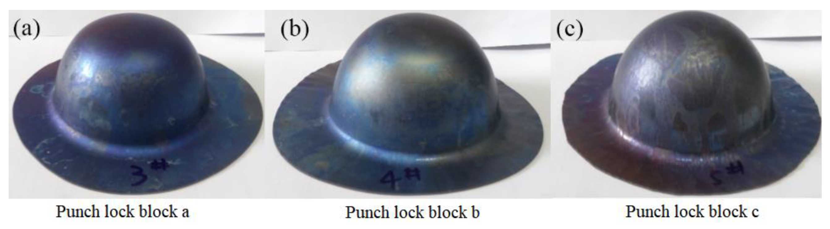
The GMF experiment on the TA1 sheet at 500 °C was conducted using three different types of punch lock blocks, and the results showed that the pressure distribution of the granular medium could be improved by using a punch lock block with a convex surface, which could also improve the formability of the sheets.
(3)
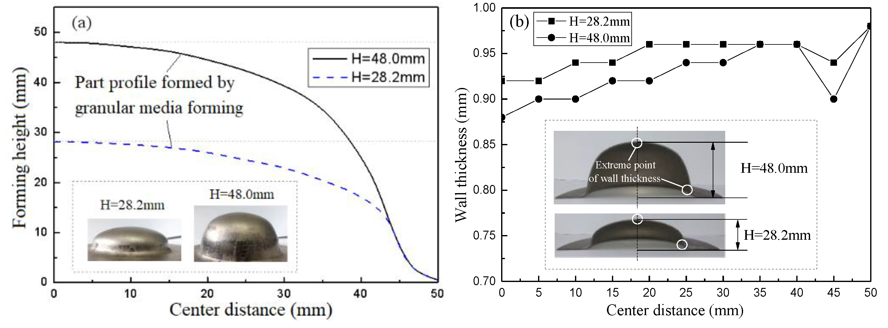
The results of the GMF experiment on the TC4 titanium alloy sheet at 500 °C showed that the contour curvature of the deformation zone at the bottom of the parts increased with a reduction in the yield strength of the blank, and, under the same drawing force, the drawing depth increased with a reduction in the yield strength of the blank.
(4)
Compared with the experimental results, an analysis of the accuracy of the calculations of three established analysis models showed that GMF technology could improve the forming properties of titanium alloy sheets at 500 °C.

Author Contributions

Conceptualization, G.C. and K.L.; methodology, G.C., K.L., C.W., and L.L.; software, J.F. and K.L.; experiments, G.C., J.F., and K.L.; validation, G.C., C.W., and K.L.; formal analysis, G.C. and L.L.; investigation, J.F.; resources, G.C.; data curation, J.F.; writing—original draft preparation, G.C. and J.F.; writing—review and editing, G.C., C.W., and J.F.; visualization, L.L.; supervision, C.W.; project administration, J.F.; funding acquisition, G.C. All authors have read and agreed to the published version of the manuscript.

Funding

This research was funded by the Key Laboratory of Advanced Manufacturing Technology of Zhejiang Province, Grant No. 2020KF06, Zhejiang Provincial Natural Science Foundation of China, Grant No. LQ18E050010, and the Scientific Research Foundation of Zhejiang Sci-Tech University, Grant No. 17022073-Y.

Conflicts of Interest

The authors declare no conflict of interest.

References

  1. Zhao, C.C.; Li, X.D.; Dong, G.J.; Wang, Y.S. Solid granules medium forming technology and its numerical simulation. J. Mech. Eng. 2009, 45, 211–215. [Google Scholar] [CrossRef]
  2. Zhao, C.C.; Wang, Y.S.; Li, X.D.; Dong, G.J.; Liu, S.B. Solid granules medium forming technology and theoretical research. J. Plast. Eng. 2007, 14, 54–59. [Google Scholar]
  3. Dong, G.J.; Zhao, C.C.; Cao, M.Y. Flexible-die forming process with solid granule medium on sheet metal. Trans. Nonferr. Metals Soc. China 2013, 23, 2666–2677. [Google Scholar] [CrossRef]
  4. Liu, K.N.; Lang, L.L.; Zhang, W.S.; Marai, M.; Liu, B.S. Coupled Eulerian–Lagrangian simulation of granular medium sheet forming process and experimental investigation at elevated temperature. Int. J. Adv. Manuf. Technol. 2017, 88, 2871–2882. [Google Scholar] [CrossRef]
  5. Lang, L.L.; Liu, B.L.; Li, T.; Zeng, Y.S. Experimental investigation on hydromechanical deep drawing of aluminum alloy with heated media. Steel Res. Int. 2012, 83, 230–237. [Google Scholar] [CrossRef]
  6. Turkoz, M.; Cora, O.N.; Gedikli, H.; Dilmec, M.; Halkaci, H.S.; Koc, M. Numerical optimization of warm hydromechanical deep drawing process parameters and its experimental verification. J. Manuf. Process. 2020, 57, 344–353. [Google Scholar] [CrossRef]
  7. Cai, G.S.; Yang, J.L.; Yuan, Y.F.; Yang, X.Y.; Lang, L.H.; Alexandrov, S. Mechanics analysis of aluminum alloy cylindrical cup during warm sheet hydromechanical deep drawing. Int. J. Mech. Sci. 2020, 174, 105556. [Google Scholar] [CrossRef]
  8. Cai, G.S.; Fu, J.B.; Zhang, D.X.; Yang, J.L.; Yuan, Y.F.; Lang, L.H.; Alexandrov, S. A novel approach to predict wrinkling of aluminum alloy during warm/hot sheet hydroforming based on an improved Yoshida buckling test. Materials 2020, 13, 1165. [Google Scholar] [CrossRef] [Green Version]
  9. Dasappa, P.; Inal, K.; Mishra, R. The effects of anisotropic yield functions and their material parameters on prediction of forming limit diagrams. Int. J. Solids Struct. 2012, 49, 3528–3550. [Google Scholar] [CrossRef] [Green Version]
  10. Qiu, G.; Henke, S.; Grabe, J. Application of a Coupled Eulerian–Lagrangian approach on geomechanical problems involving large deformation. Comput. Geotech. 2011, 38, 30–39. [Google Scholar] [CrossRef]
  11. Grüner, M.; Merklein, M. Numerical simulation of hydroforming at elevated temperatures with granular material used as medium compared to the real part geometry. Int. J. Mater. Form. 2010, 3, 279–282. [Google Scholar] [CrossRef]
  12. Chen, H.; Güner, A.; Khalifa, N.; Tekkaya, A.E. Granular media-based tube press hardening. J. Mater. Process. Technol. 2016, 228, 145–159. [Google Scholar] [CrossRef]
  13. Huang, C.Q.; Liu, L.L. Application of the constitutive model in finite element simulation: Predicting the flow behavior for 5754 aluminum alloy during hot working. Metals 2017, 7, 1–12. [Google Scholar]
  14. Cao, M.Y.; Dong, G.J.; Zhao, C.C. Research on Pressure-transfer Characteristics in the Solid Granule Medium Forming Based on the Discrete Element Method. J. Mech. Eng. 2011, 47, 62–69. [Google Scholar] [CrossRef]
  15. Mei, H.; Lang, L.L.; Liu, K.N.; Yang, X.G. Evaluation study on iterative inverse modeling procedure for determining post-necking hardening behavior of sheet metal at elevated temperature. Metals 2018, 8, 1044. [Google Scholar] [CrossRef] [Green Version]
  16. Liu, K.N.; Lang, L.L.; Cai, G.S.; Yang, X.Y.; Guo, C.; Liu, B.S. A novel approach to determine plastic hardening curves of AA7075 sheet utilizing hydraulic bulging test at elevated temperature. Int. J. Mech. Sci. 2015, 100, 328–338. [Google Scholar] [CrossRef]
  17. Grüner, M.; Merklein, M. Influences on the molding in hydroforming using granular material as a medium. AIP Conf. Proc. 2011, 1383, 645–652. [Google Scholar]
  18. Lade, P.V.; Yamamuro, J.A.; Bopp, P.A. Significance of particle crushing in granular materials. Am. Soc. Civil. Eng. 2014, 122, 309–316. [Google Scholar] [CrossRef]
  19. Yang, Z.Y.; Zhao, C.C.; Dong, G.J.; Du, B.; Zhang, L. Analytical model of corner filling with granular media to investigate the friction effect between tube and media. Int. J. Adv. Manuf. Technol. 2018, 99, 211–224. [Google Scholar] [CrossRef]
  20. Luo, K.; Zhang, L.; Wu, G.H.; Liu, W.C.; Ding, W.J. Effect of Y and Gd content on the microstructure and mechanical properties of Mg-Y-RE alloys. J. Magnes. Alloy. 2019, 7, 345–354. [Google Scholar] [CrossRef]
  21. Yuan, L.H.; Gu, D.D.; Lin, K.J.; Ge, Q.; Shi, X.Y.; Wang, H.R.; Hu, K.M. Influence of structural features on processability, microstructures, chemical compositions, and hardness of selective laser melted complex thin-walled components. Int. J. Adv. Manuf. Technol. 2020, 109, 1643–1654. [Google Scholar] [CrossRef]
  22. Hu, M.; Dong, L.M.; Zhang, Z.Q.; Lei, X.F.; Yang, R.; Sha, Y.H. Correction of flow curves and constitutive modelling of a Ti-6Al-4V alloy. Metals 2018, 8, 1. [Google Scholar] [CrossRef] [Green Version]
  23. Al-Badour, F.; Merah, N.; Shuaib, A.; Bazoune, A. Coupled Eulerian Lagrangian finite element modeling of friction stir welding processes. J. Mater. Process. Technol. 2013, 213, 1433–1439. [Google Scholar] [CrossRef]
  24. Ansari, M.A.; Samanta, A.; Behnagh, R.A.; Ding, H.T. An efficient coupled Eulerian-Lagrangian finite element model for friction stir processing. Int. J. Adv. Manuf. Technol. 2019, 101, 1495–1508. [Google Scholar] [CrossRef]
  25. Arienti, M.; Hung, P.; Morano, E.; Shepherd, J. A level set approach to Eulerian-Lagrangian coupling. J. Compt. Phys. 2003, 185, 213–251. [Google Scholar] [CrossRef] [Green Version]
  26. Cirak, F.; Radovitzky, R. A Lagrangian-Eulerian shell-fluid coupling algorithm based on level sets. Comput. Struct. 2005, 83, 491–498. [Google Scholar] [CrossRef]
Figure 1. Schematic diagram of the coupled Eulerian–Lagrangian (CEL) analysis of the forming process. EVF: Eulerian volume fraction.
Metals 11 00114 g001
Figure 2. Equivalent stress distribution for different deep drawing heights by CEL analysis.
Metals 11 00114 g002
Figure 3. Section view of the granular medium forming (GMF) experimental setup.
Metals 11 00114 g003
Figure 4. Mold parts used in the GMF experiment.
Metals 11 00114 g004
Figure 5. Testing platform and heating system.
Metals 11 00114 g005
Figure 6. Schematic diagram of the heat preservation and heating method.
Metals 11 00114 g006
Figure 7. Parts formed by GMF at room temperature under different deep drawing heights (H): (a) H was 28.2 mm and (b) H was 48.0 mm.
Metals 11 00114 g007
Figure 8. Representation of the wrinkle resistance of the GMF method.
Metals 11 00114 g008
Figure 9. Wrinkling of the parabolic thin-walled parts formed by the conventional deep drawing process.
Metals 11 00114 g009
Figure 10. Inner surface quality of the parts formed with copper foil of different thicknesses: (a) 0.2 mm and (b) 0.1 mm.
Metals 11 00114 g010
Figure 11. Form of the 0.1 mm-thick copper foil after the GMF process.
Metals 11 00114 g011
Figure 12. Dimensions and thickness distribution of the parts fabricated by GMF at room temperature (RT): (a) external profile dimensions and (b) wall thickness distribution.
Metals 11 00114 g012
Figure 13. Finite element method (FEM) simulation results of the profile curves calculated by three different models compared with the experimental data under different drawing heights: (a) the drawing height was 28 mm and (b) the drawing height was 48 mm.
Metals 11 00114 g013
Figure 14. Wall thickness distributions of the sheet for the three different models.
Metals 11 00114 g014
Figure 15. Wall thickness distribution curves calculated by the three different models compared with the experimentally measured values under different drawing heights: (a) the drawing height was 28 mm and (b) the drawing height was 48 mm.
Metals 11 00114 g015
Figure 16. TA1 parts fabricated by GMF at 500 °C with punch lock blocks of different shapes: (a) punch lock block a; (b) punch lock block b and (c) punch lock block c.
Metals 11 00114 g016
Figure 17. Parts fabricated by GMF at 500 °C: (a) external profile dimensions and (b) wall thickness distributions.
Metals 11 00114 g017
Figure 18. TC4 parts formed by GMF at 500 °C with punch lock blocks of different shapes: (a) punch lock block a and (b) punch lock block c.
Metals 11 00114 g018
Figure 19. External profile curves of parts fabricated by GMF at 500 °C.
Metals 11 00114 g019
Figure 20. Wall thickness distribution curves calculated by three different hot viscoplastic models with punch lock blocks of different shapes: (a) the stroke of the lock block was 50 mm; (b) the stroke of the lock block was 53 mm and (c) the stroke of the lock block was 55 mm.
Metals 11 00114 g020
Figure 21. External profile curves of the parts as calculated by three different hot viscoplastic models compared with the experimentally measured values.
Metals 11 00114 g021
Publisher’s Note: MDPI stays neutral with regard to jurisdictional claims in published maps and institutional affiliations.

