3.1. Tensile Behaviors
According to the manufacturer’s report [
17], ultimate tensile strength of LDX-2101 steel (780 MPa) is about 300 MPa higher than that of 441 ferritic stainless (EN 1.4509) steel rolled according to the similar schedule. It also has higher strength than 304 austenitic stainless steel (EN 1.4301).
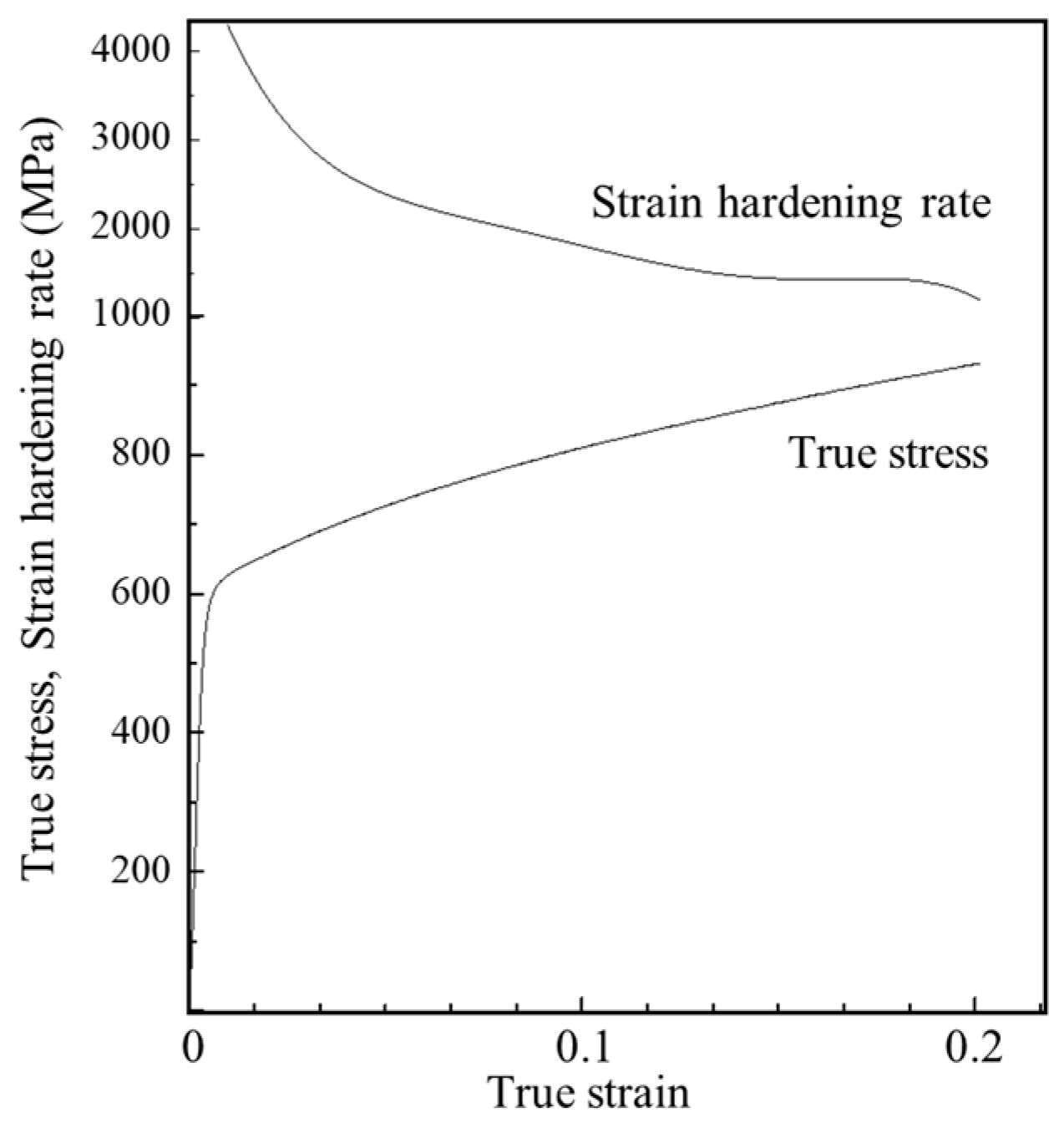
Figure 1 shows a true stress–strain curve of the DSS at room temperature when a tensile specimen was elongated to 20%. The strain hardening behavior in the true stress–strain curve was observed to occur continuously up to 20% of elongation. No serrated flow occurred.
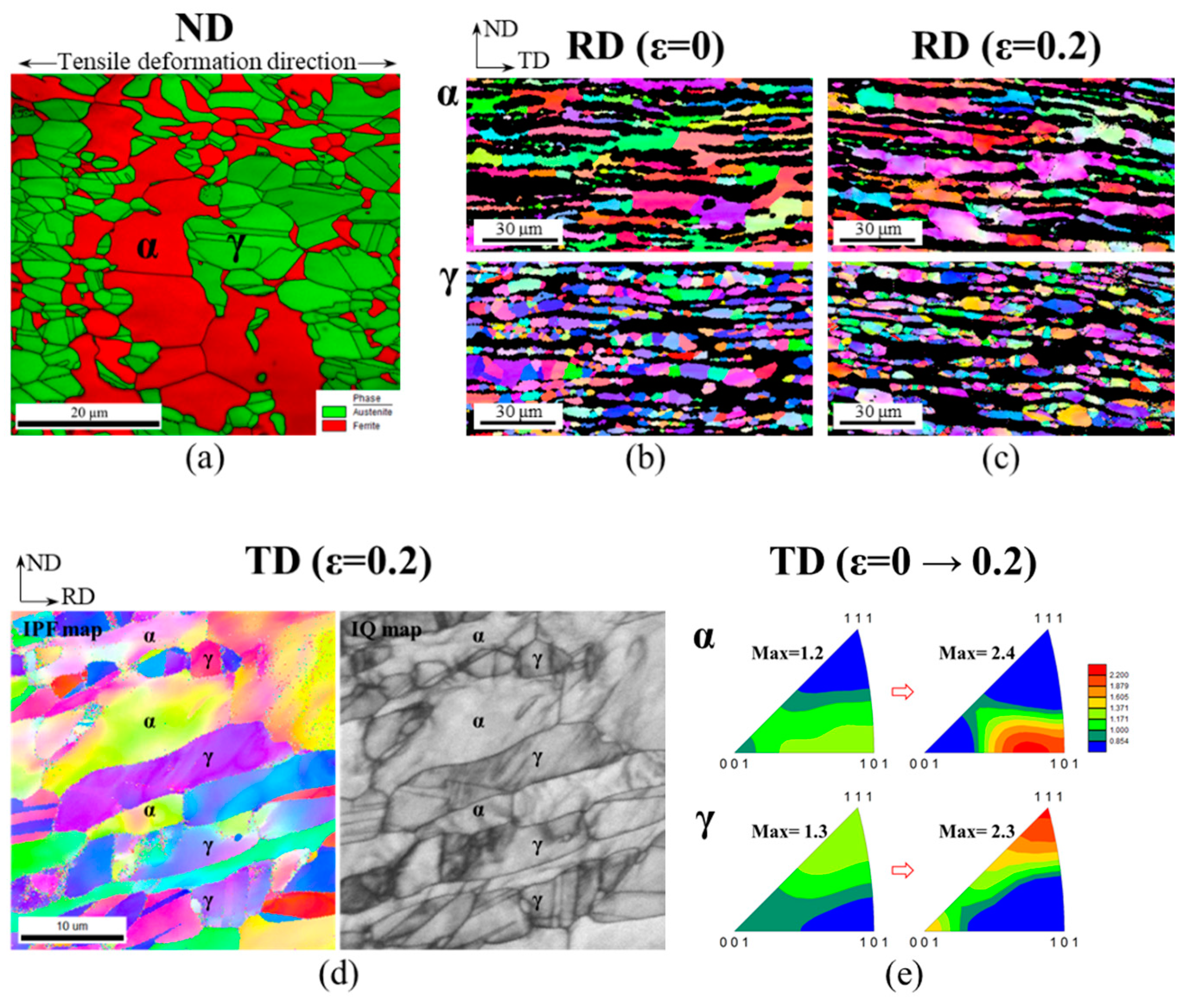
Figure 2a,b shows the EBSD microstructure images of an as-received specimen (ε = 0) of the LDX-2101 steel in the normal (ND) and sheet rolling direction (RD).
Figure 2c shows the EBSD microstructure image of the steel in the RD (⊥tensile direction) after 20% of tensile deformation. RD inverse pole figure (IPF) images (
Figure 2b,c) show two different and separate phases in the same area, indicating that this specimen has a two-phase lamellar structure. One phase is ferrite (α, bcc) with relatively large grains, and the other is austenite (γ, fcc) with smaller grains. In as-received specimens, the ferrite and austenite phases have approximately the same volume fraction, and the average grain sizes were determined to be 4.5 and 8.6 μm, respectively (
Table 2).
The intercept lengths (L
ND and L
TD) were measured along the local horizontal and vertical axes of the field scan reference frame, which corresponds to the macroscopic ND and TD of the specimen. After 20% of tensile deformation (ε = 0.2), the aspect ratio of the intercept length (L
TD/L
ND) increased by 14% in austenite and 2% in ferrite. When the austenite images in
Figure 2b,c are compared, it is clear that after deformation the thickness of the austenite band has been reduced. The difference in grain area was less than 10% in both phases, even after deformation with 20% macroscopic strain. This result indicates that the tensile deformation was accommodated by the activation of intragranular deformation mechanisms, rather than the formation of high-angle grain boundaries. This supports the idea that an internal defect investigation must be conducted to understand the role of the austenite phase in the early stage of tensile deformation.
Figure 2d shows a high magnification inverse pole figure map and an image quality map of the specimen deformed by 0.2 of strain. When the tensile strain reached 20%, deformed areas were observed to be well developed in both the ferrite and austenite grains. The tensile axis (TA-IPF) map in
Figure 2d was expected to reveal a reduced number of indexed twins because some twins were thinner than the resolution limit of the EBSD map. On the contrary, in the image quality (IQ) map in
Figure 2d, a higher number of twins is visible, appearing as straight thin dark lines.
Figure 2e shows the inverse pole figure for the crystal direction along the tensile axis (TA-IPF) before and after deformation. The initial hot-rolled state exhibited a weak texture, and that texture was sharpened during tensile deformation. This led to texture components characterized by <111>//TA and <001>//TA in austenite and <101>//TA in ferrite. Similar densities of <111> and <100> poles in austenite in the tensile direction have been observed in TWIP steels, or more generally in austenitic steels with low SFE [
18].
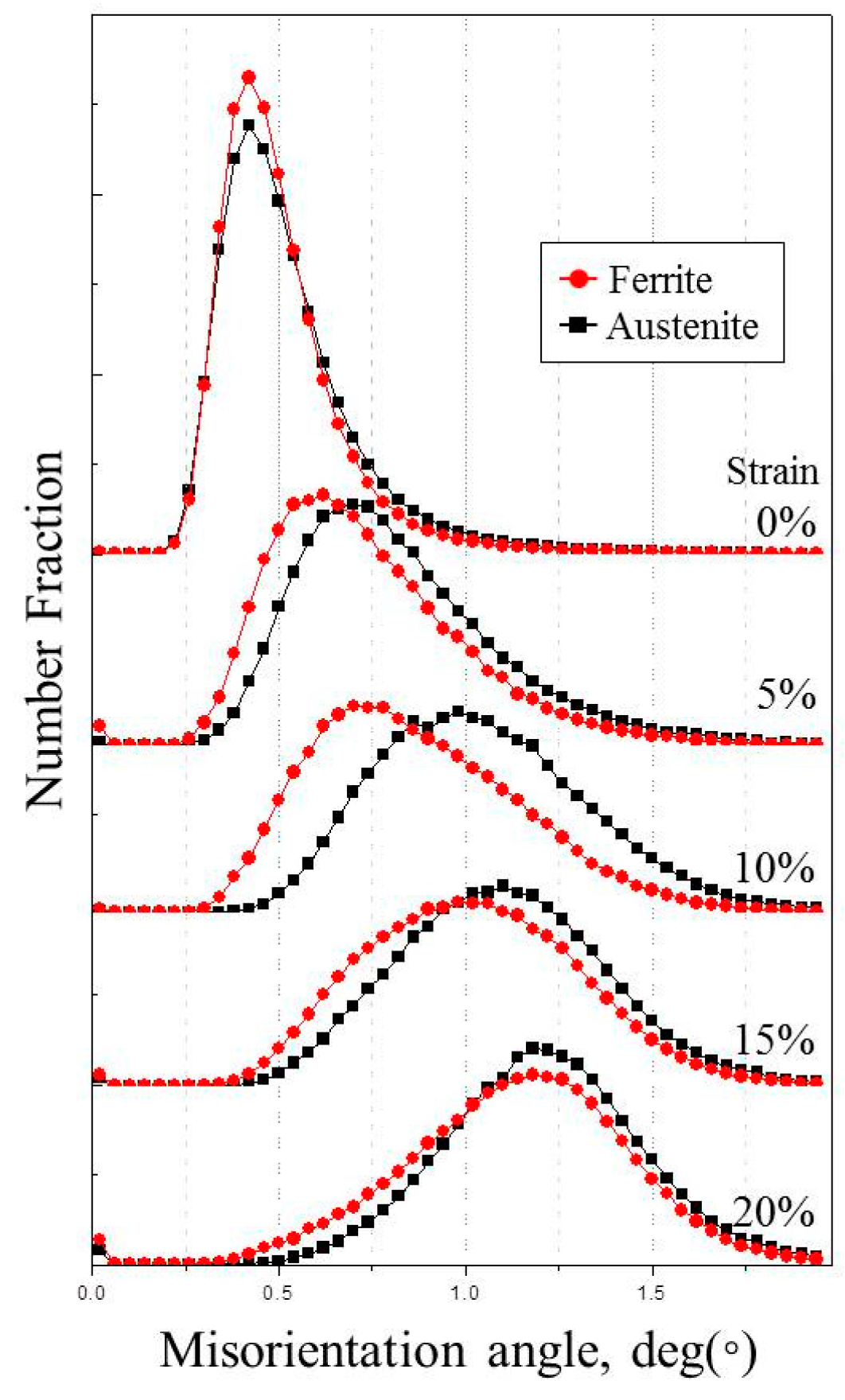
Before investigating the internal structure of the austenite grains, changes in the kernel average misorientation (KAM) of specimens with different degrees of deformation were investigated. The number fraction against misorientation angle was plotted, as shown in
Figure 3. KAM is a measure of the change in local orientation during deformation and is associated mainly with in-grain dislocation activity [
19]. Since KAM increases as the dislocation density increases, the KAM evolution with strain informs the nature of the deformation.
As shown in
Figure 3, the peak positions of the misorientation angle are the same in both phases before the tensile test. With increasing strain in the initial stage, the peak position of the austenite phase increases faster than that of the ferrite phase. The angle difference between the two phases is greatest in the 10% strained specimen. Above 10% strain, the KAM number fraction of the ferrite phase increases more rapidly and eventually reaches the same angle as that of the austenite phase at 20% strain. These results indicate that the initial strain, up to 10%, is accommodated mainly by the austenite, while further deformation is accommodated by both the austenite and ferrite.
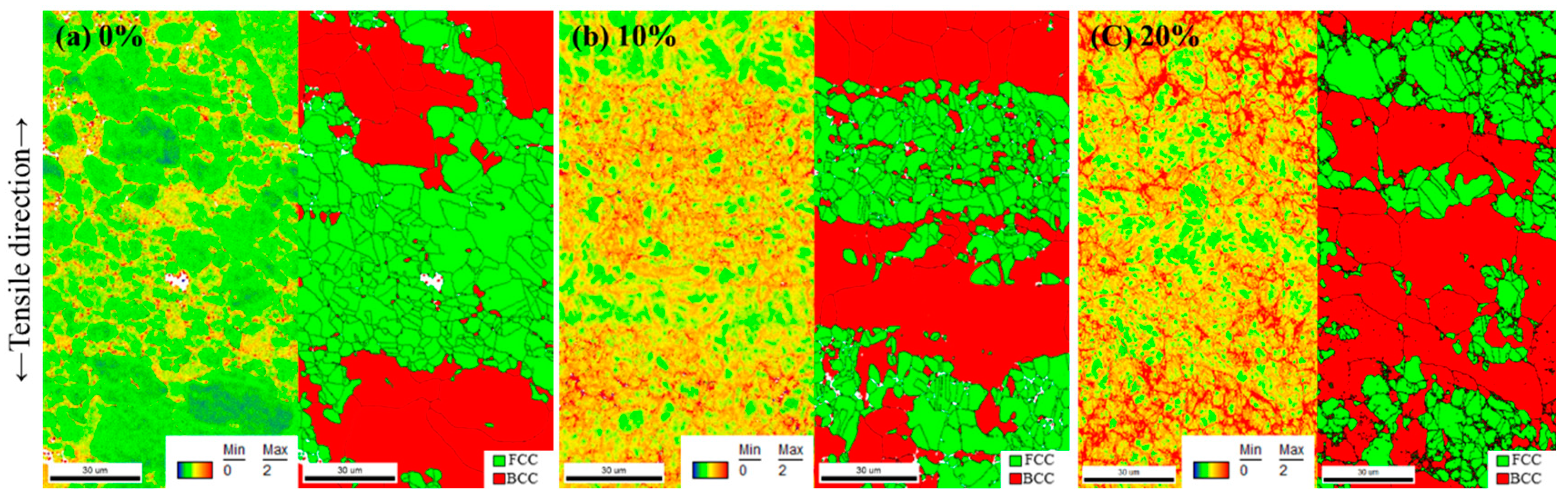
To clarify the microstructural changes, the DSS misorientation maps shown in
Figure 4 were analyzed.
Figure 4a–c shows KAM maps of the specimen under 0%, 10%, and 20% tensile strain, respectively. The largest misorientation difference between the two phases with 10% strain is shown in
Figure 3. To distinguish the two phases in the specimens, a phase map is shown on the right side of each image. In the phase map, the green area represents the austenite (fcc) phase, and the red area represents the ferrite phase (bcc). The tensile direction was parallel to the vertical direction of the images. These figures clearly show that deformed areas with a 0–2° low angle misorientation actively increased in the austenite phase at 10% deformation, and then the deformed areas were extended to the ferrite phase at 20% deformation. These deformed areas can mainly be observed in the vicinity of the austenite grain boundaries. The above microstructural changes indicate that the initial deformation at 5–10% tensile strain is accommodated mainly by the austenite phase and further deformation is accommodated by both the ferrite and austenite phases.
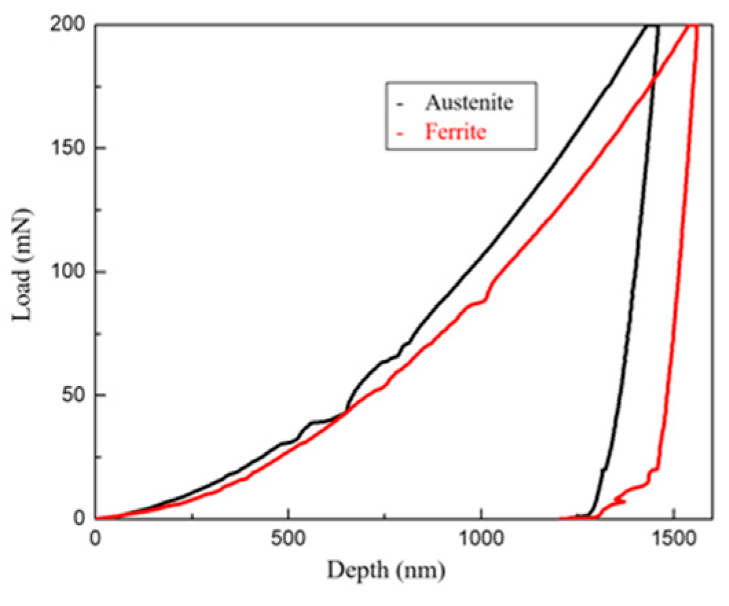
Figure 5 shows the load–displacement plots corresponding to indentations made in the ferrite and austenite phases. The increase rate of the austenite phase is steeper than that of the ferrite phase, indicating the austenite has higher strain hardenability than the ferrite. As shown in
Figure 2, the initial deformation was mainly accommodated in austenite grains, due to their lower yield strength. However, as the deformation preceded further, the overall deformation strain should be accommodated in both austenite and ferrite grains because the hardening rate of austenite is slightly higher than that of ferrite. This can explain the homogeneous deformation and high elongation of the DSS, despite the existence of two different phases.
In this section, it is observed that the LDX-2101 alloy has laminated ferrite and austenite grains elongated along the rolling direction. Under the quasi-static loading in the transverse direction, the specimen exhibited the excellent strength and ductility. The strain-hardening was provided steadily enough to sustain the uniform elongation up to 20%. The microstructural observation using the KAM and EBSD analysis reveals the strong influence of austenite phase on the strain hardening rate. To clarify the deformation mechanism, it is necessary to observe more detailed defect structures using TEM.
3.2. Microstructural Changes with Increasing Strain
In the previous section, the KAM analysis of tensile specimens indicated that the austenite phase plays a significant role in the deformation behaviors of LDX-2101 steel in the early stage of deformation, and that this can be attributed to the formation of mechanical twins. To investigate the deformation modes and twin characteristics of the austenite, a TEM analysis of the LDX-2101 steel was carried out on the austenite phase under various tensile strains.
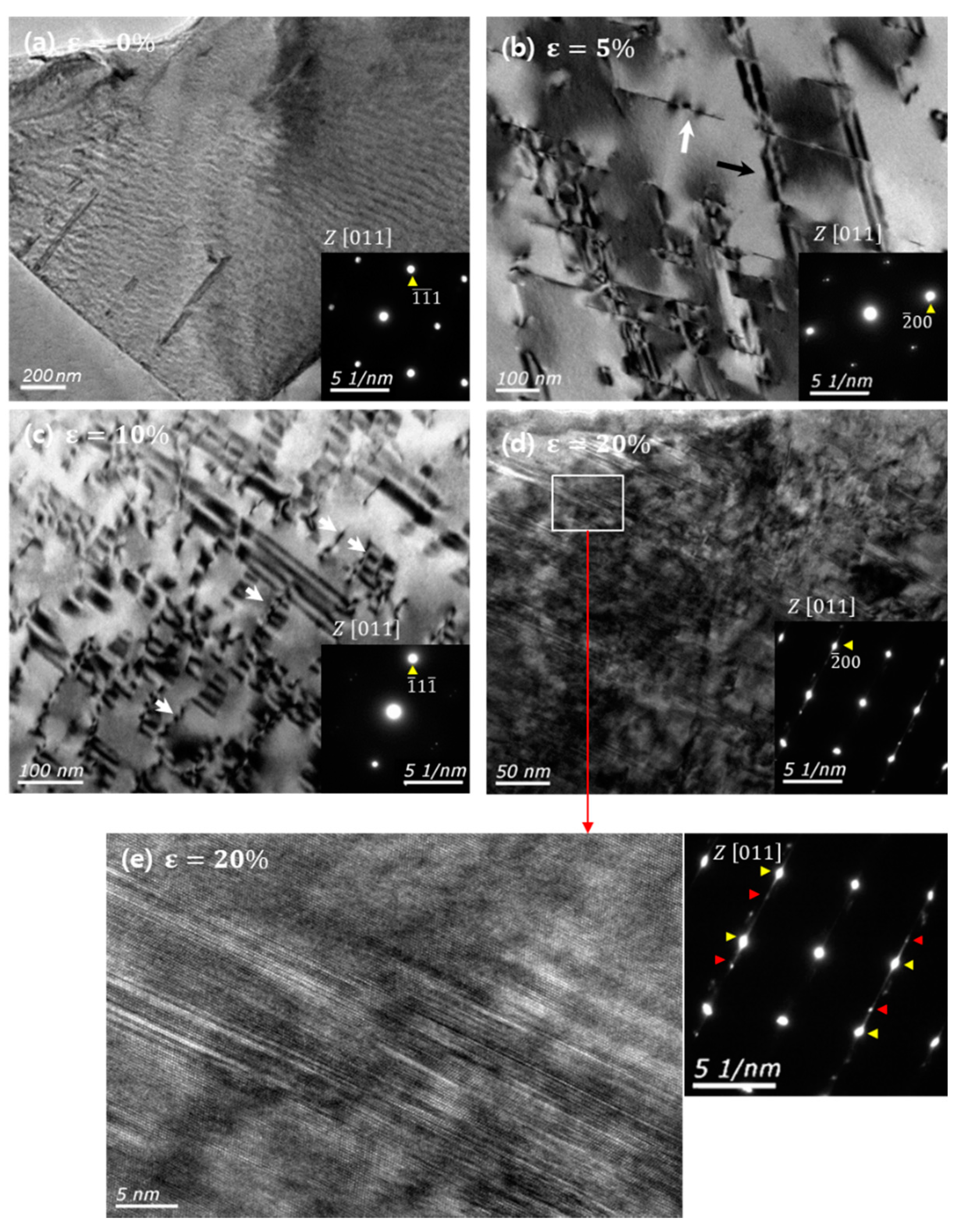
Figure 6a–d shows TEM bright field micrographs of austenite grains of 0%, 5%, 10%, and 20% tensile deformed specimens, respectively, all observed in the [011] zone axis.
Figure 6a shows that a few SFs and strain fields have developed in the austenite grains. As shown in
Figure 4a, in the as-received specimen, misorientation deviation has developed at the grain boundaries. This is attributed to the stress that occurs during the steel-making process [
6] and is in good agreement with the TEM image. As shown in
Figure 6b, SFs are formed quasi-uniformly in austenite grains after 5% strain. When a stacking fault plane is perpendicular to the diffraction zone, the stacking fault appears as a line in the TEM image, as indicated by the white arrows in the figure. When the specimen is tilted to a certain angle from the zone axis, the SFs feature can be identified, as indicated by the black arrow in the figure.
Figure 6b shows that SFs are formed on two planes. The spacing of the arrays of SFs is more than 100 nm, on average.
Figure 6c,d shows that additional defects developed in one plane even after the deformation had considerably progressed. A further increase in strain, to 10%, increased the amount of SFs that cover grains, as shown in
Figure 6c. Under the two-beam diffraction condition, stacking faults in the LDX-2101 steel were determined to be extrinsic SFs surrounded by the Shockley partial dislocations. Several partial dislocations are indicated by white arrows in
Figure 6c. Stacking fault and dislocation substructures are discussed in detail in the next section, with Figures 8 and 9. Twin diffraction patterns were rarely found in this specimen. It is speculated that the SFs in the 10% tensile deformed state were caught in the process of superposition and the creation of mechanical twins.
In contrast, twins were formed in the 20% strained specimen (
Figure 6d,e), with boundaries located on the plane parallel to the stacking fault plane. The average distance between the SFs has been reduced to about 10 nm.
Figure 6d shows the SFs, placed diagonally throughout the grain. The area marked by a rectangle has been magnified to indicate the size of the generated twins, and the nanoscale deformation twin boundaries and the diffraction pattern (inset in
Figure 6e) can be clearly observed.
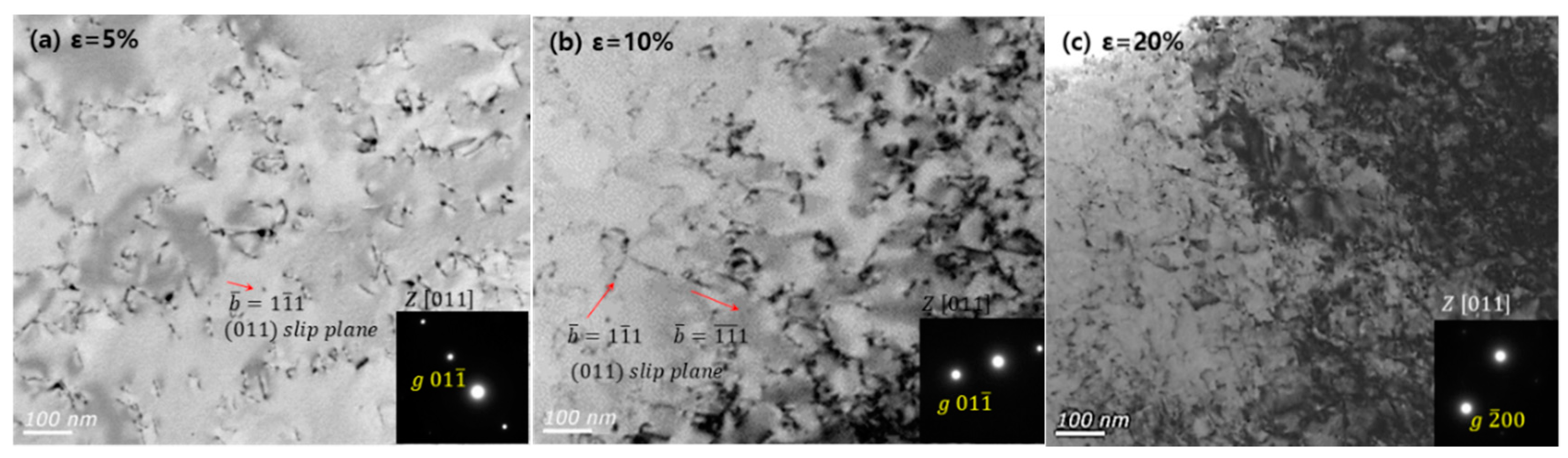
Figure 7 shows changes in the ferrite microstructure with increasing strain. As shown in the figure, it is clear that the deformation mechanism observed in the ferrite is due to the generation and multiplication of wavy glide dislocations. The increase in the amount of KAM observed in
Figure 3 can be explained by the increase in dislocations. Based on these microstructural changes, it seems clear the strain in the ferrite grains is mainly accommodated by dislocation glide because wavy glide dislocations in ferrite have higher three-dimensional mobility. In contrast, the planar glide of partial dislocations in austenite with low SFE is limited on the stacking fault plane. Ojima et al. [
19] suggested that the planar glide of dislocations leads to relatively higher local in-grain internal stress compared to the wavy glide. This is very consistent with the experimental microhardness measurement results shown in
Figure 5. Therefore, the ferrite deformation is considered to have relatively less contribution to the strain hardening of LDX-2101 alloy.
In previous studies on deformation twinning [
9,
10,
11], researchers suggested that the formation of stacking faults in austenite occurred prior to mechanical twinning in low-SFE fcc metals. As shown in
Figure 6a–c, SFs have formed before mechanical twinning. The active formation of SFs can explain why the highest KAM difference is observed between the two phases in the 10% strained specimen, as shown in
Figure 3. It is known that SFs can contribute significantly to the plasticity of the specimen because the local stress field created by stacking faults limits the glide direction of dislocations in proximity [
16]. With the further increase of plastic deformation, mechanical twin nuclei are initiated by some configuration of SFs. This is also supported by the TEM observation, showing that SFs and mechanical twins are placed parallel to the same (111) plane. It is known that mechanical twins also act as barriers to dislocation movements [
16]. In summary, the strain hardening behavior, with a tensile strength above 700 MPa as the deformation progressed to 20%, appears to be the result of interactions between incremental SFs and dislocations, and the formation of mechanical twins in later stage of deformation. These twins and SFs can interfere with the progression of moving dislocations and provide a continuous strain hardening phenomenon. In particular, SFs are observed at the beginning of deformation and have a great influence on the work hardening of the alloy from the early stage of deformation.
It is generally accepted that the stacking fault energy (SFE) of the austenite phase plays a critical role in the deformation mode. Previous reports have contended that mechanical twins become the dominant deformation mode when the SFE value is in the range of 18–45 mJ/m
2. When the SFE is less than 18 mJ/m
2, the primary deformation mechanism changes from mechanical twins to the martensitic transformation of austenite. The dislocation glide becomes dominant when the SFE is larger than 45 mJ/m
2 [
5].
Among various thermodynamic models, the thermodynamic model suggested by S. Curtze et al. was used to calculate the SFE of the DSSs in the present study [
4,
5,
20]. This model requires compositional information of the austenite grains. The electron probe microanalysis (EPMA) measurements showed that there was no compositional change in the substitutional alloying elements of the ferrite and austenite grains. However, nitrogen was more prevalent in the austenite grains, likely because of the low nitrogen solubility of ferrite. Accordingly, for the calculation the nitrogen content in austenite was corrected to 0.4 wt%. The SFE of the DSS calculated with the modified composition was 22.9 mJ/m
2. This result is consistent with the observed microstructural changes in austenite, and the formation of stacking faults and mechanical twins rather than the formation of martensite and dislocation networks, with increasing tensile strain.
As shown in
Figure 6, the diffraction patterns of mechanical twins could only be identified when the deformation reached 20%. Compared to a series of austenitic TWIP steels [
16,
21], duplex stainless steels exhibit deformation-induced twins at higher strain ranges. This can be explained by the relationship between stacking fault energy and the critical resolve shear stress (CRSS) for twins. The following equation for critical twinning stress was proposed by Chen et al. [
21,
22] and simplified by Hirth and Lothe [
21,
23]
According to the above equation, CRSS is dependent on SFE. Using a value of 0.147 nm for the length of the Burgers vector of a partial dislocation (b
p), and a value of 13.2 mJ m
2 for the SFE, the CRSS for mechanical twinning was calculated to be 89 MPa by Lee for the Fe
12Mn
0.6C alloy [
21]. For the LDXs used in this study, the CRSS value was therefore calculated to be 156 MPa using the same
bp value and the SFE of 22.9 mJ/m
2 calculated earlier. This value is much higher, about 1.75 times that of the
τ for TWIP steel. This result explains why the LDX requires a greater amount of deformation to produce deformation twins.
The above TEM analysis showed that austenite in LDX accommodated deformation strain through the progressive process of deformation twinning. Contrary to the previous studies on TWIP steels with higher strain hardening rates caused by twin boundaries that hinder the dislocation movement [
16,
24], twins were formed in a relatively high strain region (
) in this alloy due to its higher SFE than the TWIP steels. Thus, this alloy requires new explanation for the initial work hardening behavior. The TEM analysis of dislocation substructures revealed that as the strain increased, the number of SFs on the primary slip plane increased and SFs started overlapping. Thus these overlapped SFs, acting as nuclei of deformation twins, played a critical role in sustaining the ductility in a strain range of 0~10%.
3.3. Mechanical Twin Generation Mechanism
The properties of the stacking faults in the DSS can be examined by using the relationship between the diffraction vector and the stacking fault fringe contrast [
25,
26,
27].
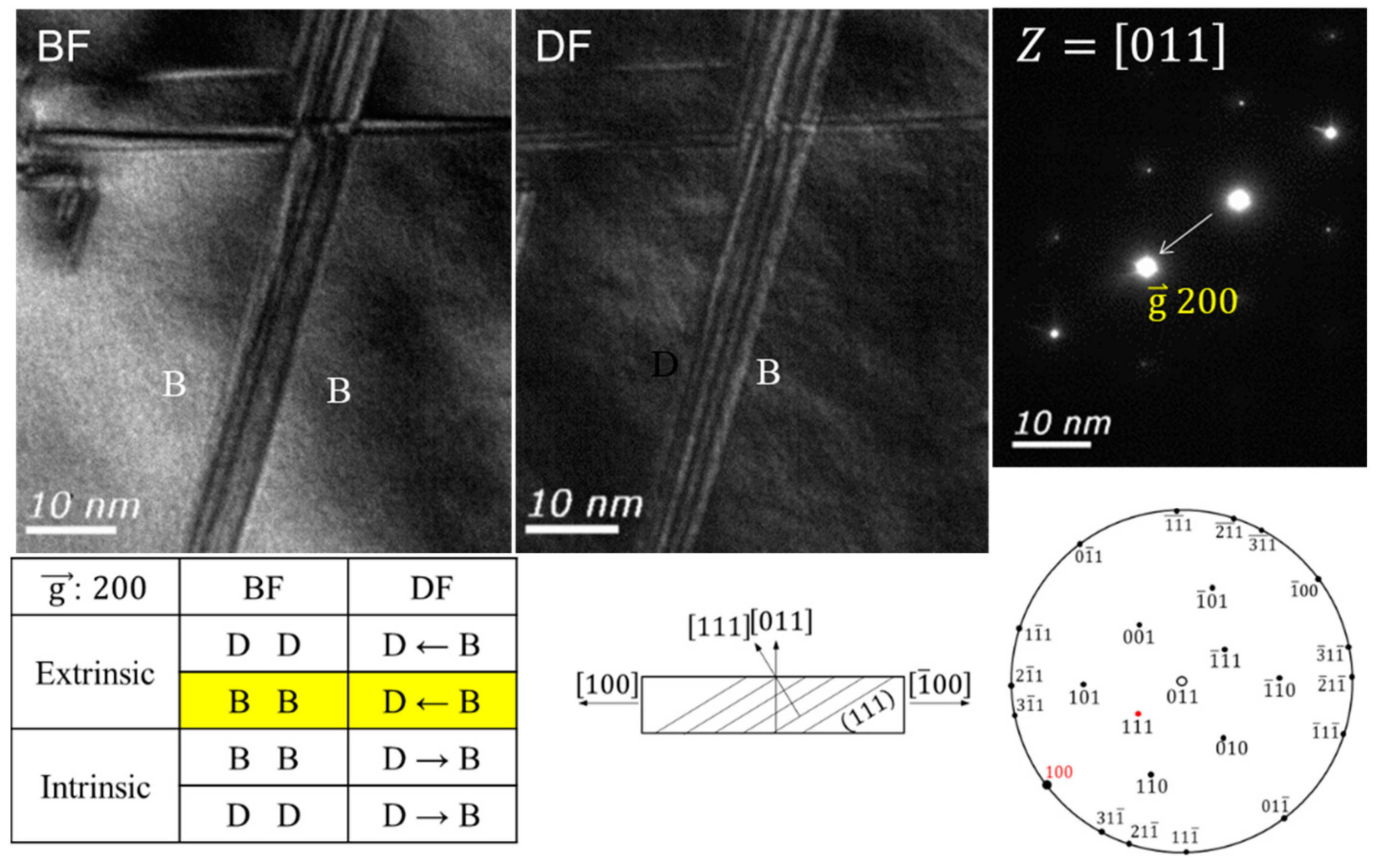
Figure 8 shows the bright and dark field image of a stacking fault in a 10% tensile strained LDX-2101 sample, under a (200) two-beam diffraction condition. The direction of the (200) plane vector is indicated by the dark outline direction of the stacking fault, indicating that this stacking fault has an extrinsic property. By applying this method to multiple areas in multiple TEM specimens, it was possible to confirm that the stacking faults in this study mainly had an extrinsic property.
To characterize the dislocations involved in mechanical twinning, the invisibility criteria [
25,
26,
27,
28] were used under TEM two-beam conditions. Evaluation of the twin generation mechanism was carried out using a 10% tensile tested sample of LDX-2101 steel because the defect density was moderately high. This made it possible to characterize partial dislocations without defect superimposition, which was observed in the 20% tensile tested specimen.
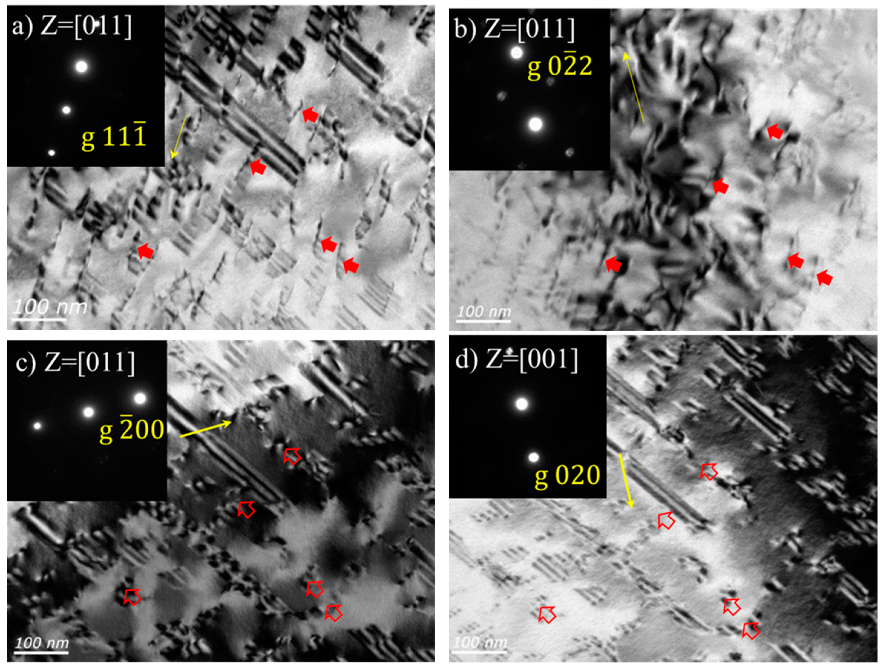
Figure 9 shows TEM images of dislocations, obtained from the same area on the <011> and <001> zone axes under the two-beam condition. The corresponding diffraction patterns are included in the upper left side of each image. The visible and invisible conditions of Shockley and Frank partial dislocations on the <011> and <001> zone axes are listed in
Table 3. When the g
b is less than a half, dislocations are generally invisible [
26].
To clarify these changes in relation to the two-beam condition, five representative partial dislocations were arbitrarily selected as examples and are indicated by arrows in
Figure 9. The hollow arrows indicate a partial dislocation under the visible condition, while the filled arrows indicate a dislocation under the invisible condition. As a consequence, it was determined that the five partial dislocations have a Burgers vector of
.
Using the extended theory proposed by Silcock and Tunstall [
7,
9,
28], it was also confirmed that no dislocation exhibited the Frank characteristics. The Frank partials with a Burgers vector of
show a so-called ‘reversal of contrast’ using 002 and
reflections and a strong contrast under the 220 reflection, although the value of
was calculated to be zero in the [110] zone axis.
Mechanical twin generation mechanisms in austenite have been proposed by several researchers [
7,
16,
24]. They have suggested various dislocation reactions to explain the formation of a mechanical twin. These reactions can be divided into three groups, based on how perfect dislocations are divided into partial dislocations [
7]. The mechanisms and their characteristics are summarized in
Table 4 according to the reactions. The twin formation mechanism in LDX-2101 steel can be determined by comparing the dislocation responses discussed in
Table 4 with the dislocation characteristics analyzed in this study. As shown in the representative
Figure 9, prior to forming mechanical twins, stacking faults of the extrinsic type are located on the same plane and possess mainly one kind of Shockley partial dislocation. This makes it reasonable to consider the three-layer twin formation theory to be the main mechanical twin formation mechanism in the LDX-2101 alloy.
In the pole mechanism, the tensile strain behavior is governed by immovable Frank partial dislocations that are already present in the specimen before deformation, i.e., the pole partials [
16,
24]. This suggests that immovable Frank dislocations exist before deformation, and their density increases with the increasing number of stacking faults produced during tensile deformation. In the LDX-2101 steel, however, as observed by TEM, the Shockley type partial dislocation appears more stable than the pole dislocation. This is supported by the apparently large number of Shockley partial dislocations. In addition, it was observed that most of the staking faults were external.
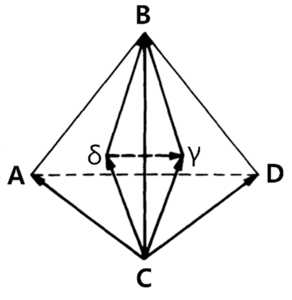
In the SRCS mechanism, a partial dislocation on the primary slip plane (δB in
Figure 10) dissociates into a stair-rod dislocation (δγ) and twinning partial dislocation on the conjugate slip plane (γB) [
24]. The mechanical twin formed following this dislocation reaction (
Table 4) should be on the conjugate plane. According to the observations in this study, the dominant formation of mechanical twins was on the primary slip system. For example, in
Figure 6d, a mechanical twin can be observed parallel to the primary stacking faults. At a later stage of deformation, the SRCS mechanism may be possible, where the formation of stacking faults on the conjugate surface is sufficient.
The microstructural analysis confirmed that the three-layer twin formation mechanism was the main mechanical twin formation mechanism in LDX-2101. The strain hardening phenomenon in
Figure 5 is consistent with the microstructural development of the specimen, since only the three-layer twin mechanism can account for the stacking faults and twin generation phenomena on the primary surface.
The microstructural observation of LDX-2101 alloy showed that the initial deformation was localized in austenite grains by the formation of SFs along the primary slip system, resulting in parallel dense SF arrays containing deformation twins in their interiors. This can explain that the deformation twins were formed by following the three-layer twin mechanism. In this alloy, the continuous work hardening phenomenon was observed in the strain range of ~20% without any abrupt increase frequently observed in TWIP steels. This delayed deformation twinning of this alloy resulted from the higher SF energy of this alloy. Thus, the microstructural evolution revealed the SFs provided a continuous work hardening from the early stage of the deformation, and ferrite grains also accommodated the deformation in the strain range of 10 to 20%. This mechanical behaviors of the LDX-2101 alloy lead to the superior combination of strength and ductility.


