Article

Investigation and Minimization of Slag Spot Surface Defects in Continuous Casting of High Carbon Steel Billets through Statistical Evaluation

1
Iron and Steel Research Institute, Wuhu Xinxing Ductile Iron Pipes Co., Ltd., Wuhu 241000, China
2
College of Materials Science and Engineering, Chongqing University, Chongqing 400044, China
*
Author to whom correspondence should be addressed.
Metals 2020, 10(7), 878; https://doi.org/10.3390/met10070878
Submission received: 9 June 2020 / Revised: 20 June 2020 / Accepted: 30 June 2020 / Published: 1 July 2020
(This article belongs to the Special Issue Mold and Tundish Metallurgy)

Abstract

:
Slag spot surface defects often appear during continuous casting of high carbon steel billets due to the solidification characteristics of molten steel in the mold. To target the problem of surface slag spot defects that occur frequently during the continuous casting of high-carbon steel strands, we analyzed the influence of molten steel superheat, accumulated service time and the water inlet temperature of the mold, the size of the submerged entry nozzle and the physical and chemical properties of the mold powder on the slag spot defects. The production practice shows that by adjusting the superheat of molten steel to 30–35 °C, the water inlet temperature of the mold is stable at 33–35 °C. To adjust the internal and external diameter of the immersion nozzle to 30–70 mm, the viscosity and melting temperature of the mold powder were adjusted from 0.45–0.55 Pa·s, 1100–1140 °C to 0.15–0.25 Pa·s, 1020–1060 °C. The final billet surface quality was improved significantly, the billet surface was smooth, the oscillation marks were relatively smooth and regular and the slag trench ratio was reduced from the original maximum of 40–50% to less than 1%.

1. Introduction

High-carbon steel is characterized by a low liquidus temperature; a large segregation of elements C, P and S in the steel; and a poor plasticity at high temperature [1]. Under the action of the hydrostatic pressure of the molten steel, the contact between the shell and the mold wall is relatively close and the gap is small. Compared with low-carbon-steel casting, high-carbon steel is more likely to be blocked by slag rim during casting. The slag rim is typically formed near the meniscus due to excessive powder insertion into the mold and the liquidus temperature of molten steel is relatively low. This rim presses on the surface of the initially solidified shell and because it is relatively soft at this temperature scratch marks can form and is retained even after the steel exits the mold, a soft shell will form a long and thin ‘slag spot’ defect. Slag spot is easy to appear in high-carbon steel such as SWRH82B, GCr15 steel. After the billet exits the mold, if the corresponding slag thickness at the slag spot is insufficient to resist the hydrostatic pressure of the molten steel, steel leakage will occur. Furthermore, when the slag spot is deeper or shallower and without timely grinding, cracks will form in the rolling material during the rolling, which will affect the final product yield.
Research and analysis was conducted to understand the problem of slag spot on the surface of high-carbon steel billet. We usually use “slag trench ratio” to judge the severity of slag spot of billets. The slag trench ratio is the value of the number of billets with slag spot divided by the total number of billets in a certain pouring time. Che et al. [2] studied the surface defects of large-section high-carbon round steel billets and showed that an optimizing of the continuous casting mold powder and an improvement in the pouring performance can control the slag spot. Guan et al. [3] studied defects of slag spot on the surface of 70 steel billet and found that a reduction of the taper of mold and an improvement in performance of the mold powder could reduce the billet slag trench ratio. Chen et al. [4] analyzed the slag spot on the surface of GCr15 bearing steel billets and found that an adjustment of the continuous casting process and an optimization of the physical and chemical indices of the mold powder can resolve the slag spot. Adepu [5] and other studies have shown that the accumulation of silicate inclusions is the main reason for the formation of slag spot, and an increase in the turbulence velocity at the meniscus helps to reduce the probability of slag spot generation. Sohn [6] found that low-viscosity mold powder helps in the casting of high-carbon steel at a high casting speed. However, the above-mentioned technological measures to reduce slag spot are inconsistent or contradictory to process practice. For example, in terms of slag optimization, some steel plants reduce—and some increase—the mold powder viscosity. In terms of mold cooling, some steel plants adopt process measures to increase cooling, but some have weakened mold cooling, without systematic investigation and analysis.
To target surface slag spot defects that occur frequently during the production of high-carbon steel, we selected SWRH82B high carbon steel from certain plant as the research object. We analyzed various factors that affect the generation of slag spot defects and proposed optimization measures that have a certain practical guiding significance.

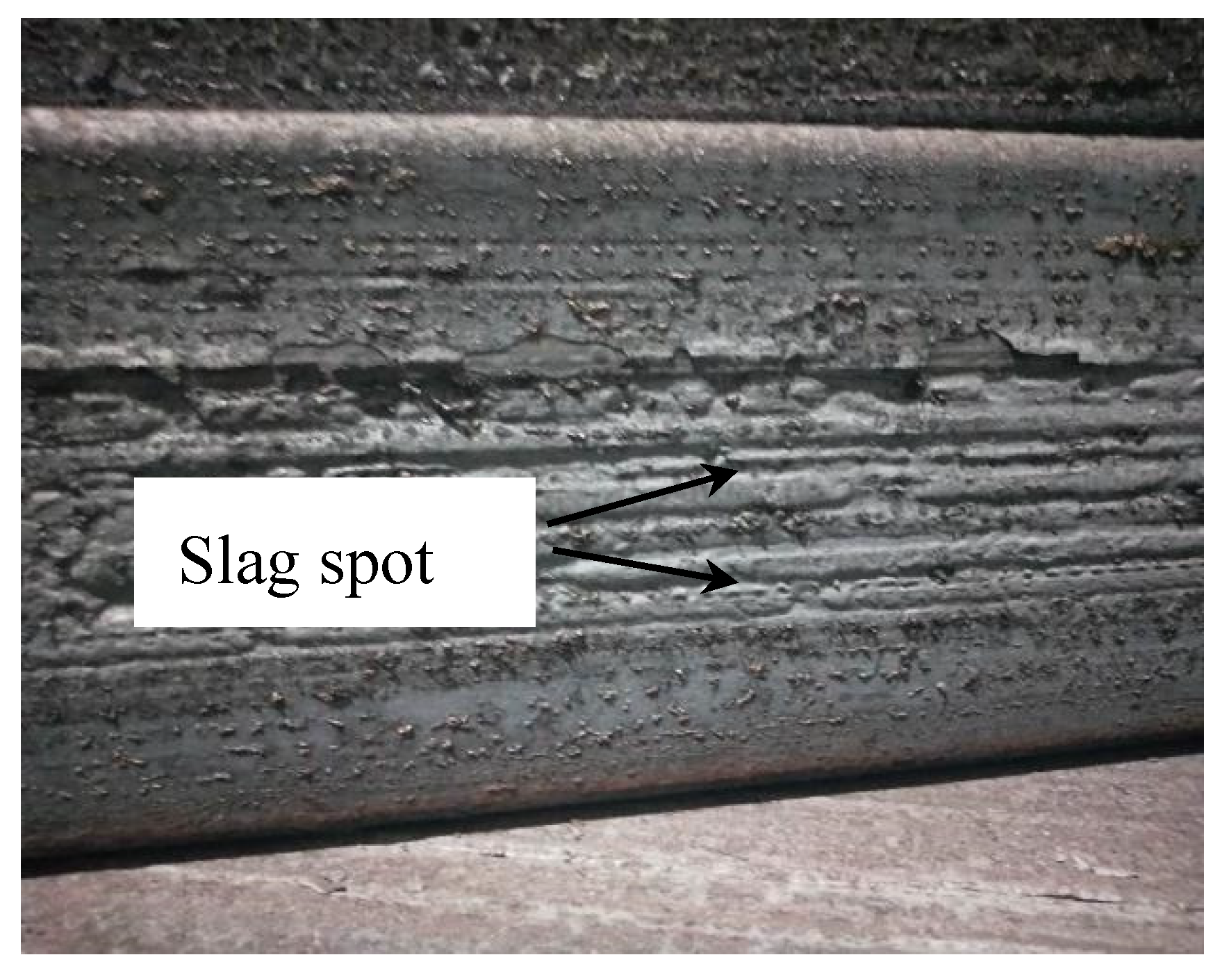
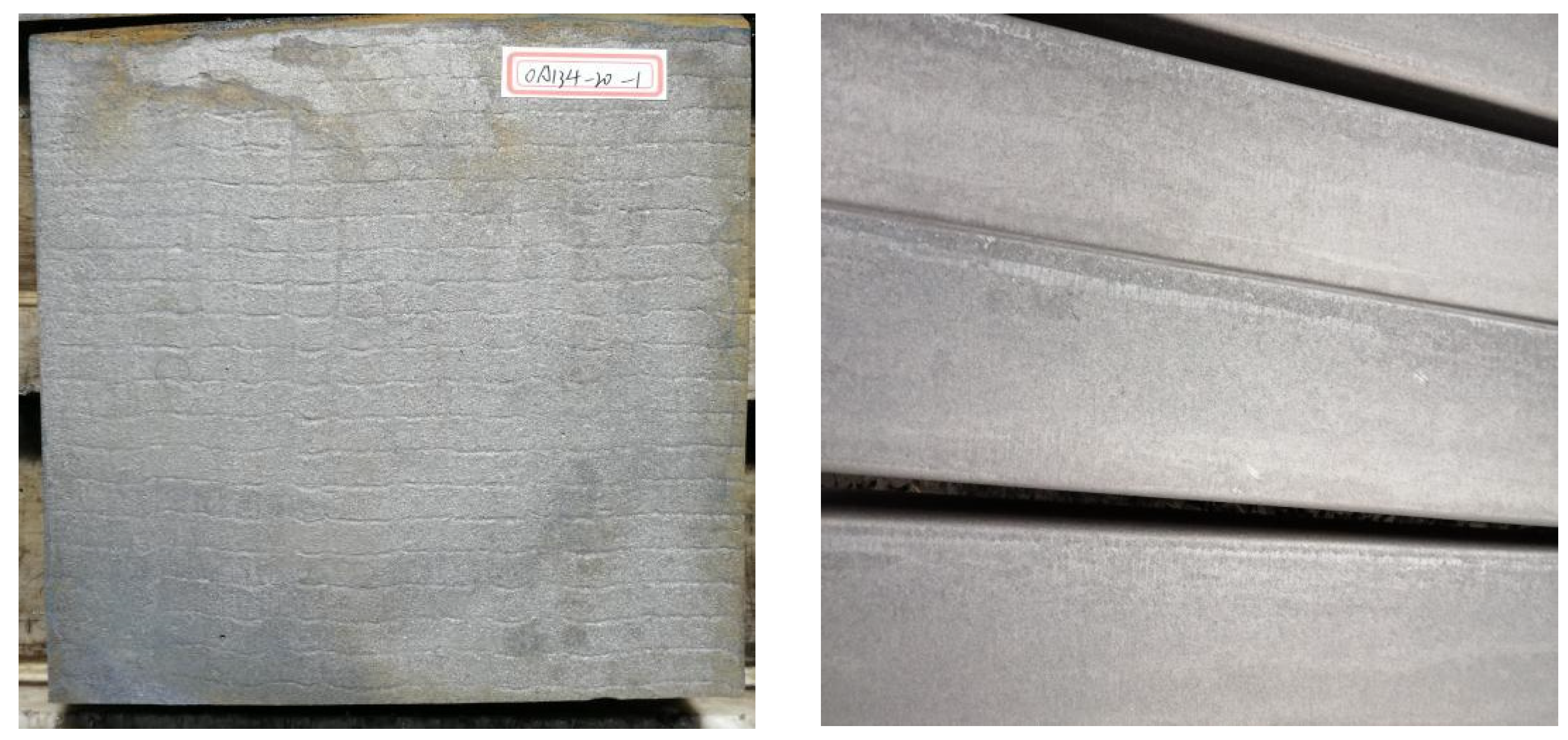
2. Surface Observation of Slag Spot Defects on As-Cast Billets

SWRH82B high-carbon steel is used mainly as a raw material to produce prestressed steel strands and has a wide range of application in high-speed rail, highways, bridges, water conservation, environmental protection and other fields [7,8,9,10,11]. The production process of the SWRH82B continuously cast billet includes a 120-t converter and a ladle metallurgical furnace subsequently casting in a 10-strand-180-mm-by-180-mm billet continuous caster. The chemical composition of the SWRH82B high-carbon steel that is produced is shown in Table 1.
The typical slag spot morphology on the SWRH82B billet surface is shown in Figure 1. The slag spots are characterized mainly by multiple fine and long groove defects on the surface, the slag groove width is ~2–3 mm, the length and depth are not fixed, and some groove defects with deep solder joint leakages exist in the middle. In serious cases, the slag trench ratio reaches 40–50%, which results in huge economic loss to the manufacturers.

3. Analysis of Influencing Factors of Slag Spots

Based on the solidification characteristics of high-carbon steel, the generation of slag spot is related closely to the lubrication behavior of the billet in the mold. Therefore, the influencing rules and trends of the superheating of molten steel, the accumulated mold service time, the inlet water temperature of the mold, the size of the submerged nozzle, and the physical and chemical properties of the mold powder on the defects of slag spot were investigated.

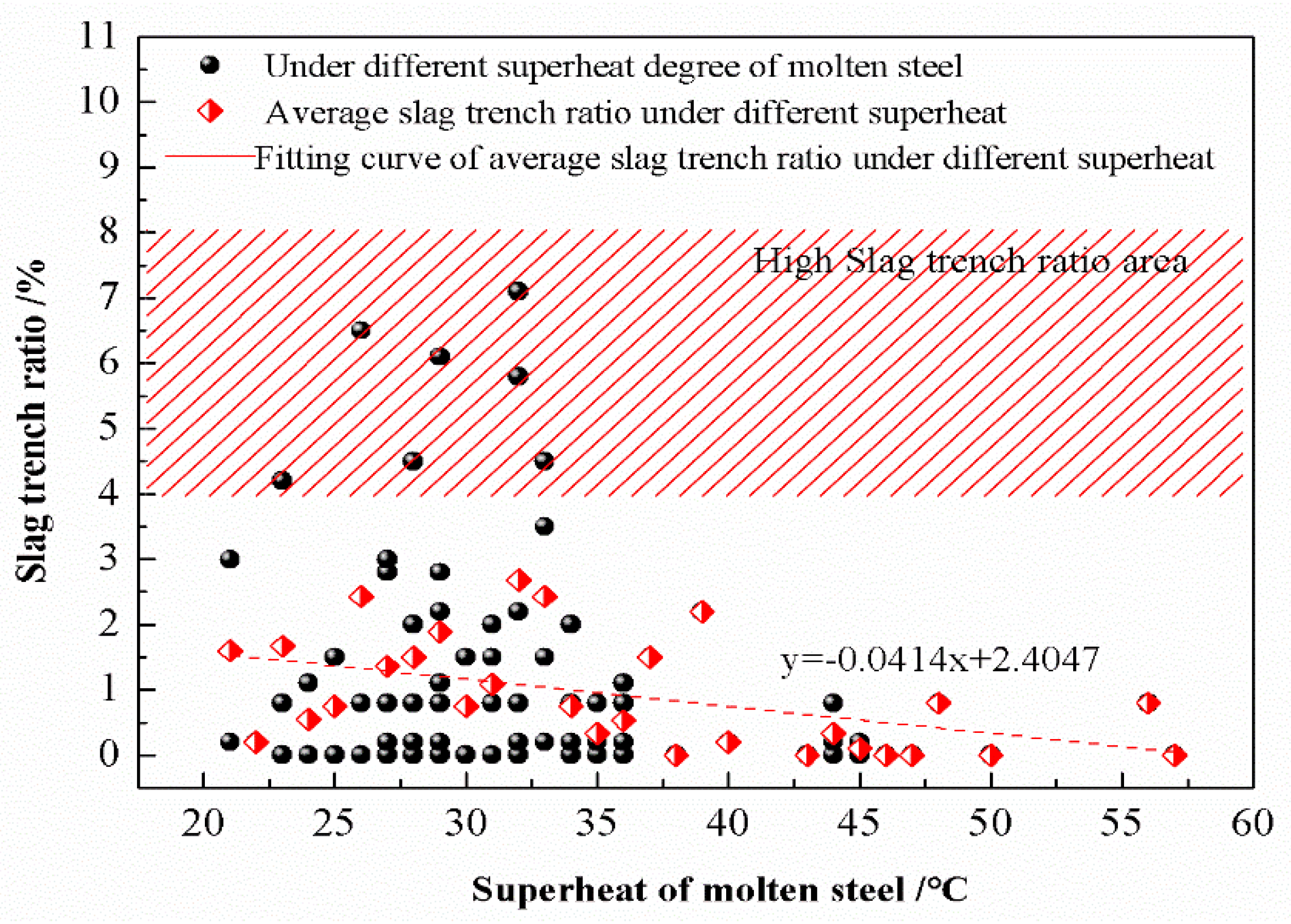
3.1. Molten Steel Superheat

As an important parameter to measure casting in continuous casting, the superheat of molten steel will affect the stability of the casting process. When the superheat is too high, the number of casting sequences in a tundish is shortened, which places a burden on the cooling stage of the continuous casting mold and yields internal billet quality problems [12,13,14,15]. In contrast, when the superheat is too low, the temperature of molten steel is close to the liquidus temperature of the steel, it is easy to cause molten steel nodulation, which is not conducive to the floating of inclusions [16]. The direct effect of superheat on the slag trench ratio of the billet has rarely been reported. To analyze whether there is a relationship between the superheat degree and the generation of SWRH82B slag trench ratio, data statistics of the proportion of slag spot to total slag spot for different superheat degrees of the 73 heats SWRH82B steel that was produced at the plant from November to December 2018 were used, as shown in Figure 2.
The superheat control standard of the SWRH82B steel must be between 20 and 45 °C. Figure 2 shows that the high slag trench ratio occurs mainly in the range of the superheat degree of 20–35 °C, but when the superheat degree exceeds 35 °C, the slag trench ratio is maintained below 1% and the fluctuation range is small. If the melting point of the mold flux is high, the slag agglomerates and slag spots will form easily when the superheat of the molten steel is low. The liquid slag layer thickness will also be reduced because of the lack of heat in the upper part of the mold, which results in the poor lubrication of the billet and slag spots. The above is confirmed at the production site. The superheat cannot be too high because of internal billet quality requirements. Therefore, the superheat degree of molten steel is controlled at 33–38 °C, which ensures that the slag trench ratio remains low, and avoids an impact on carbon segregation.

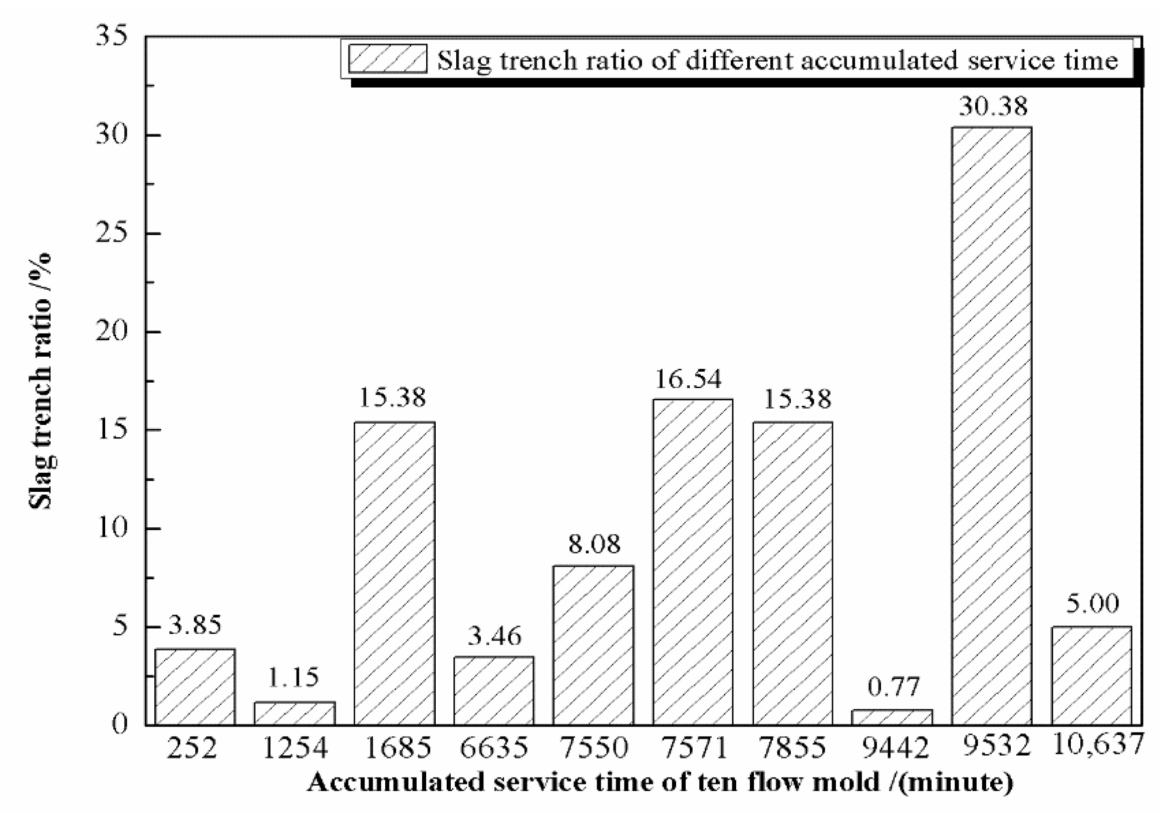
3.2. Accumulated Service Time of the Mold

With a continuous increase in the amount of steel passing through the mold, the mold exit will gradually wear out, so the reverse taper of the new mold is larger than that of the middle and later molds. However, because of the small shrinkage of the SWRH82B high-carbon steel, the gap between the mold wall and the shell is small [17,18]. Theoretically, a large reverse taper of the new mold can easily lead to uneven flow of liquid slag into the gap, and the channel will be blocked to form a slag rim, which is more likely to cause slag spots. To study whether a correlation exists between the accumulated service time of the mold and the slag trench ratio, the relationship between the accumulated service time of ten flow molds of a certain pouring time of SWRH82B and the slag trench ratio was analyzed statistically, as shown in detail in Figure 3.
Figure 3 shows that ten strands of the casting were used in the early (0–3000 min), middle (3000–7000 min) and later stages of the mold (7000 min). The highest proportion of the slag trench ratio was 1685, 7571, 7855 and 9532 min, and the lowest proportion of slag trench ratio was 252, 1254, 6635 and 9442 min. Therefore, according to the statistical results, it is not found that a new mold is more likely to yield slag spot, which indicates that the accumulated service time of the mold in this plant has no relationship with the generation of SWRH82B slag–trench ratio.

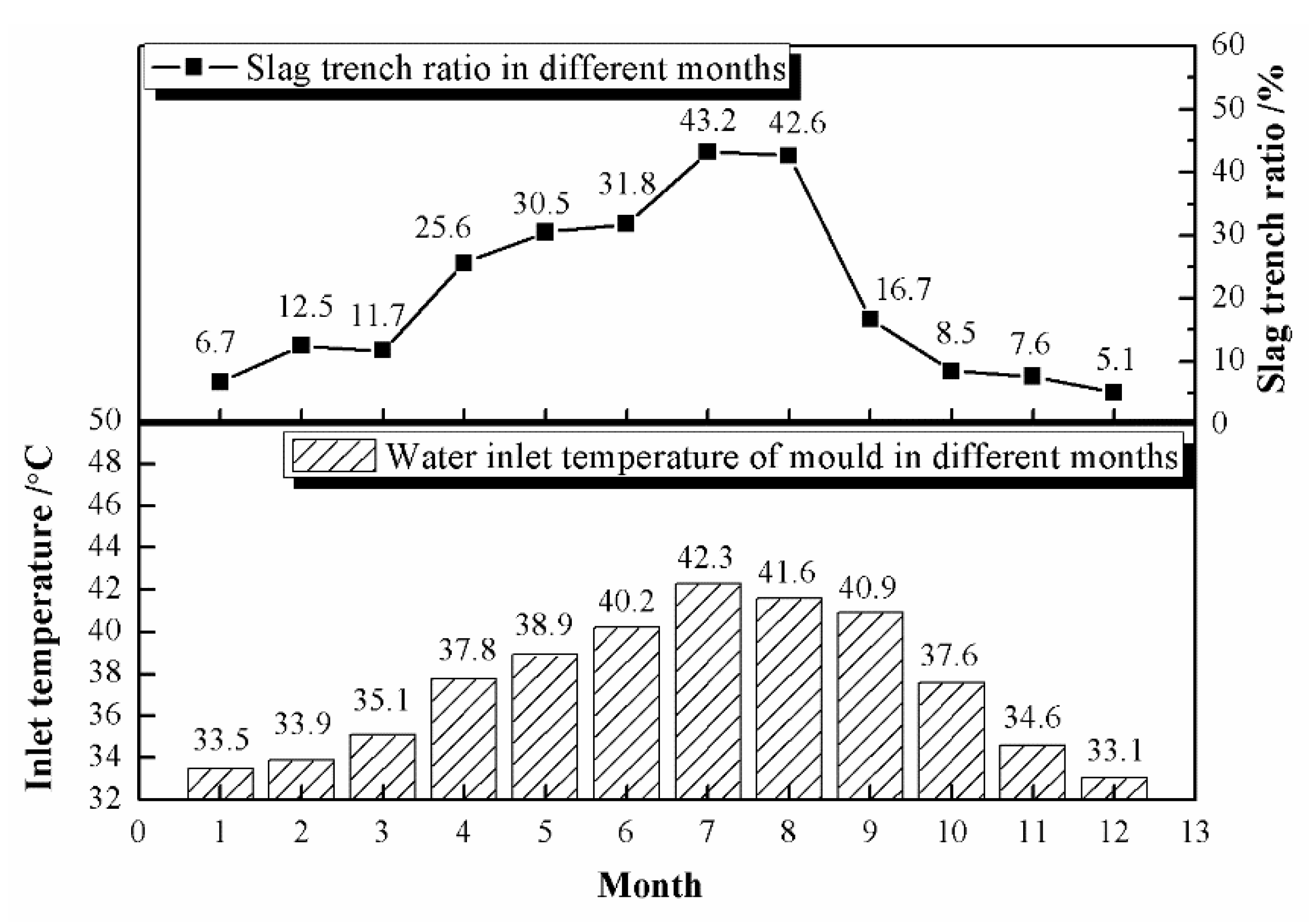
3.3. Inlet Water Temperature of the Mold

Because of the cooling capacity of the cooling tower, the inlet water temperature of the mold of this plant was affected significantly by the climate in different months. To analyze the relationship between the inlet water temperature of the mold and the slag trench ratio, the relationship between the inlet water temperature of the mold and the slag trench ratio from January to December 2018 was calculated statistically, as shown in Figure 4.
Figure 4 shows that the inlet water temperature of the mold over 2018 increased initially and then decreased. The inlet water temperature of the mold changed constantly with the seasonal change of climate. In winter, the inlet water temperature of the mold was lowest, falling below 33.1 °C. In summer, the inlet water temperature of the mold was the highest, at up to 42.3 °C, giving a range of 9.2 °C. In 2018, the slag trench ratio showed an increasing initial trend and then a decrease. The slag trench ratio was lowest in winter and reached as low as 5.1%. The slag trench ratio was highest in summer, reaching as high as 43.2%. In conclusion, the trend in Figure 4 indicates that the inlet water temperature of the mold has a certain influence on the slag trench ratio of the SWRH82B. From the mechanism analysis, the same inlet and outlet water temperature mold differences and different inlet mold temperatures will affect the heat transfer effect of the mold. A higher mold water inlet temperature will result in a weaker heat-transfer effect. Meanwhile, during the months of July to August, the temperature is relatively high, and the humidity is high, the superheat may also be slightly higher, which will cause the shell to become thinner and contact the mold wall more closely. If the working conditions are unstable or the performance of the mold powder does not match, a slag spot will form because of poor lubrication under the action of the solid shell.

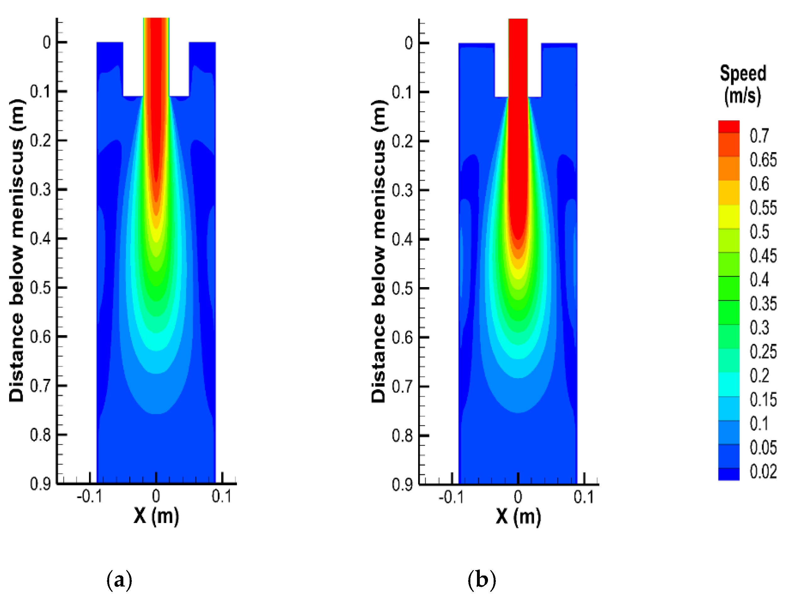
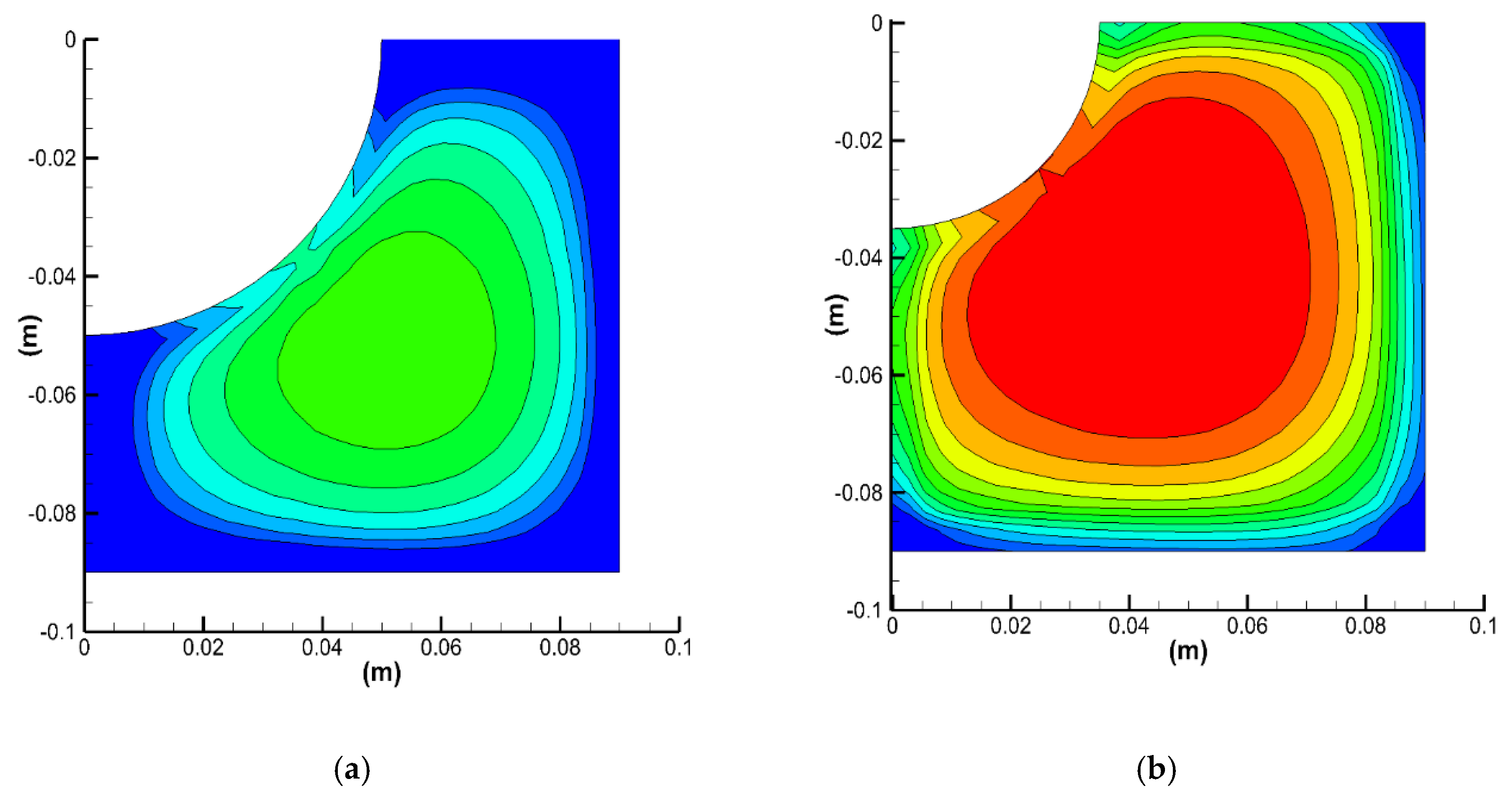
3.4. Size of Submerged Entry Nozzle

Mold submerged nozzle-casting technology is used extensively in domestic modern billet continuous casting production, and the structural parameters of the submerged entry nozzle will affect the metallurgical behavior of the molten steel in the mold. This will in turn affect the melting and inflow of the mold powder, the floating of inclusions, the involvement of the slag, the level fluctuation and the uniformity of the initial shell [19,20,21,22]. Currently, the submerged entry nozzle with an inner diameter of 40 mm and an outer diameter of 100 mm is used in 180 mm × 180 mm billet continuous casting in this plant. The mold powder on the surface of the molten steel accumulates easily when the meniscus of the mold is observed during field casting. Some researchers have shown that the flow field, temperature field uniformity, and the stable control of the meniscus in the mold can be improved by optimizing the submerged entry nozzle diameter at an appropriate insertion depth, to provide a metallurgical function to the mold powder. Shuai et al [23]. provided a numeric analysis of the influence of a submerged nozzle of a 160 mm × 160 mm billet on the flow field and temperature field of the mold, and found that at a constant insertion depth of the submerged entry nozzle, with an increase of the inner nozzle diameter of the nozzle, the flow rate of the molten steel in the mold decreased, the temperature of the molten steel decreased, and the meniscus fluctuation was relatively stable. According to previous research results and combined with the current production situation at the plant, an optimization of the structural parameters of the submerged nozzle is of great significance for continuous casting stability and to improve the surface quality of the SWRH82B.
The plant used FLUENT software to study the effects of two types of submerged entry nozzles with inner and outer diameters of 40–100 mm and 30–70 mm on the fluid flow and the temperature in the mold. Due to the complexity of the transfer phenomena during continuous casting, the current study assumed that the level fluctuation and the mold oscillation was ignored, there was no mold flux at the meniscus. In addition, the effect of solidified shell on the flow was neglected, only the heat transfer was taken into account.
The comparison of flow speed in Figure 5 shows that when the inner-outer nozzle diameter changes from 40–100 mm to 30–70 mm, the flow velocity at the outlet of the nozzle increases from 0.65 to 0.70 m/s at the same constant flow rate, the flow velocity at the lower side of the outlet exceeds 0.30 m/s. the jet flow velocity increases and the flow field near the liquid surface becomes active. The impact depth of the main molten steel stream from the nozzle is ~600 mm.
The comparison in Figure 6 shows that under the same working conditions, when the inner–outer nozzle diameter changes from 40–100 mm to 30–70 mm, the area above 1738 K at the meniscus was enlarged visibly and the maximum temperature increased by ~2 K. This corresponds with the increase of active area distribution of the flow field near the meniscus in Figure 5. For the active area, the high-temperature liquid steel from the nozzle is replenished with time and the meniscus temperature remains high.
The numeric simulation results show that under current small-section continuous casting, when the inner and outer diameter of the straight-through nozzle changes from 40–100 mm to 30–70 mm, the flow velocity at the lower side of the outlet exceeds 0.30 m/s and increases significantly and the impact depth of the two nozzles does not change much. The area above 1738 K at the meniscus was enlarged visibly. The change of nozzle structure made the meniscus active and the temperature increased. This temperature increase favors mold powder melting at the steel slag interface, which makes the mold powder flow into the gap between the shell and the mold more evenly and improves the lubrication effect of the shell.

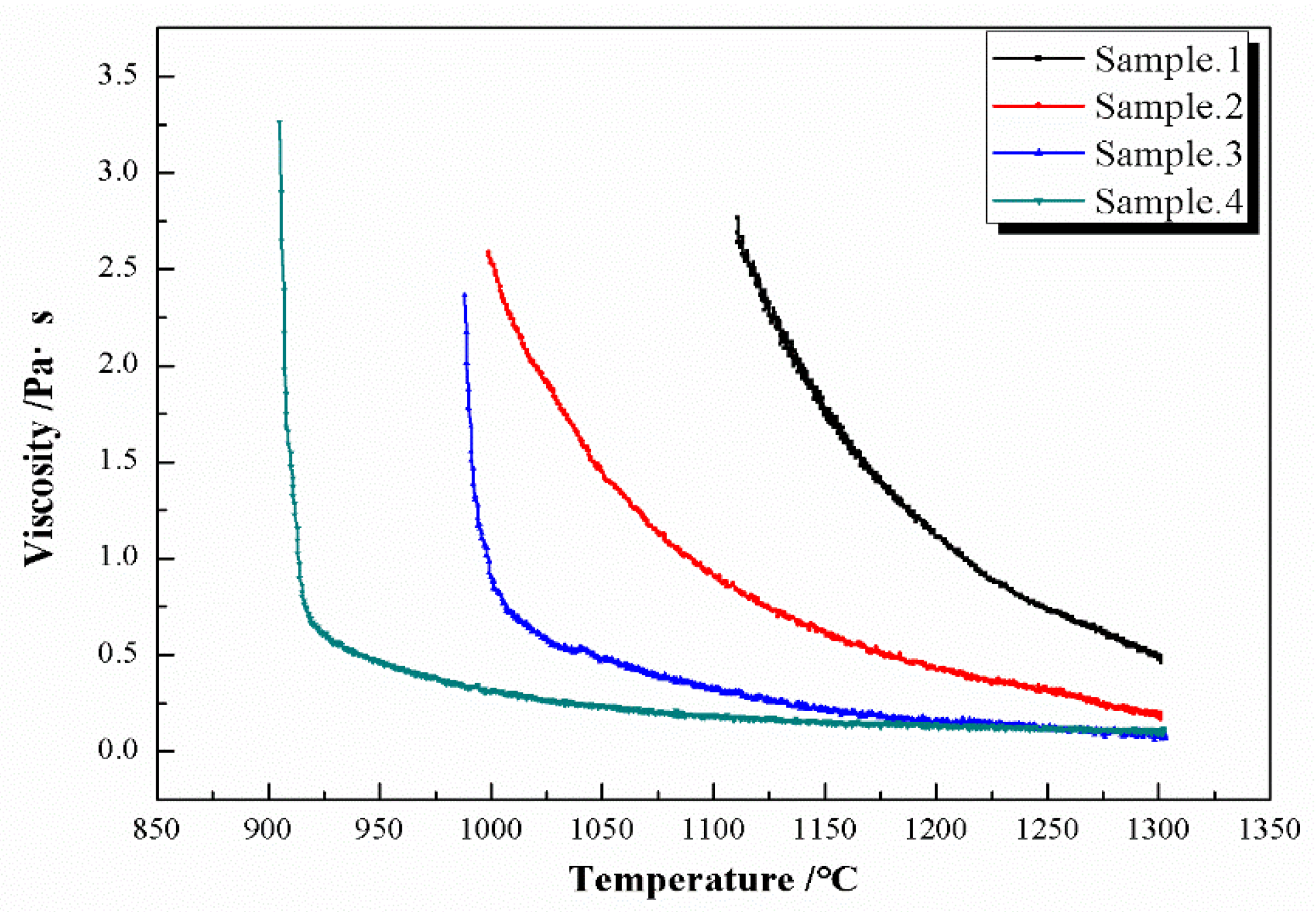
3.5. Physical and Chemical Properties of the Mold Powder

As an important functional material in continuous casting, proper physical and chemical properties of the mold powder are key to improving the continuous casting efficiency and the surface quality of the billet [24,25,26,27]. Due to the relatively high melting temperature and viscosity of the mold powder of SWRH82B steel, and the small gap between the high carbon steel billet shell and the mold wall, the consumption of SWRH82B steel mold powder in the plant is ~0.189 kg/t on average during production and application, whereas the normal consumption of SWRH82B steel mold powder should exceed 0.3 kg/t. Too low a consumption of mold powder will lead to a poor lubrication effect of the billet, easy agglomeration and the formation of slag spots. The thickness of the liquid slag layer that was measured on site varied from 6 to 7 mm, which is lower than the normal standard of ~10–12 mm. This occurs because the melting point and viscosity of the mold powder were relatively high. The liquidus temperature of the high-carbon steel was too low, and the pouring temperature of the molten steel was lower than other steel grades, which is not conducive to mold powder melting, so the liquid slag layer thickness of the mold powder was relatively low. The physical and chemical properties of the original mold powder cannot meet the requirements for the use of SWRH82B steel. It is necessary to optimize the physical and chemical indices of the mold powder to improve the lubrication effect of the billet. A reasonable reduction of viscosity and melting temperature of the mold powder and several optimization tests were carried out to obtain the most suitable physical and chemical parameters of the mold powder. The application test results of the mold powder with different physical and chemical parameters are shown in Table 2, in which No. 1 is the original SWRH82B steel mold powder for comparison, and No. 2–4 is the improved mold powder. The viscosity temperature curves of the four slag samples are shown in Figure 7.
According to the application test results of the mold powder with different physical and chemical parameters, it can be seen that when the mold powder viscosity is reduced to 0.15–0.25 Pa·s and the melting temperature is reduced to 1020–1060 °C, the average consumption of the mold powder increases from the original 0.189 to 0.308 kg/t, the slag trench ratio is reduced significantly, and no quality defects existed at a low magnification. However, when the mold powder viscosity is reduced to 0.05–0.15 Pa·s and the melting temperature is reduced to 940–980 °C, although the slag trench ratio is also reduced, corner and subcutaneous cracks were found on the low-power surface. This indicates that the viscosity and melting point of the mold powder cannot be too low. Therefore, the physical and chemical parameters of No. 3 sample were used in the plant.

4. Statistical Evaluation and Application Effect

The above investigation results show that an increase in the cooling strength of the mold, a promotion of the melting of the mold powder, and the lubricating effect on the billet favor a reduction in the occurrence of slag spots. Based on this information, to resolve the problem of high slag trench ratios of SWRH82B high-carbon steel in this plant, an optimization of the molten steel superheat, the inlet water temperature of the mold, the size of the submerged nozzle and the physical and chemical properties of the mold powder were proposed. The superheat of the molten steel was adjusted from 20–50 °C to 30–35 °C, the inlet water temperature of the mold was stabilized at 33–35 °C, the inner and outer diameters of the submerged nozzle were adjusted from 40–100 mm to 30–70 mm, the viscosity and melting temperature of the mold powder were adjusted from 0.45–0.55 Pa·s, 1100–1140 °C to 0.15–0.25 Pa·s, 1020–1060 °C. After stable production and application, the surface quality of the SWRH82B steel billet was improved significantly, the slag trench ratio was reduced from 40–50% to less than 1%, and the yield of rolled products was increased from 81% to 95%. Figure 8 shows the surface quality of SWRH82B high-carbon steel billet after improvement. The surface is smooth and the vibration mark is relatively flat and regular.

5. Conclusions

The influencing factors of slag spots for SWRH82B steel were investigated. The following conclusions were drawn.
  • The surface quality of the SWRH82B steel has slag spots. The molten steel superheat, the inlet water temperature of the mold, the structure of the submerged nozzle and the physical and chemical parameters of the mold powder are root causes for the high slag trench ratio;
  • To resolve the problem of slag spots on the SWRH82B steel billet surface, the molten steel superheat was adjusted to 30–35 °C, the inlet water temperature of the mold was stabilized at 33–35 °C, the inner and outer diameters of the submerged nozzle were adjusted to 30–70 mm, the viscosity and melting temperature of the mold powder were adjusted from 0.45–0.55 Pa·s, 1100–1140 °C to 0.15–0.25 Pa·s, 1020–1060 °C;
  • After application of the optimized process parameters, the mold powder consumption were relatively flat and regular and the slag trench ratio decreased from 40–50% to less than 1%.

Author Contributions

Formal analysis, Y.-f.C. and L.Z.; investigation, Y.-f.C. and X.-t.Z.; resources, L.Z., Q.-n.T. and H.-b.Z.; data curation, Y.-f.C., H.L. and Q.-q.W.; writing—original draft preparation, Y.-f.C.; writing—review and editing, S.-p.H.; supervision, S.-p.H.; funding acquisition, S.-p.H. All authors have read and agreed to the published version of the manuscript.

Funding

This research was funded by Natural Science Foundation of China, Grant Number 51874057.

Conflicts of Interest

The authors declare no conflict of interest.

References

  1. Barrie, M. The influence of composition on the hot ductility of steels and to the problem of transverse cracking. ISIJ Int. 1999, 39, 833–835. [Google Scholar]
  2. Che, C.R.; Ge, Q.W.; Xu, G.L.; Wang, J.Y. Optimization and application of protective slag for large section high carbon steel round billet of Huaihua steel. Mod. Metall. 2017, 45, 37–40. [Google Scholar]
  3. Guan, W.B.; Wang, Z.; Zhu, J.; Song, M.M. Analysis and optimization the reason of surface slag-scratch defect of casting billet on No.70 steel. Shanxi Metall. 2019, 181, 21–22. [Google Scholar]
  4. Chen, L.Y.; Zhang, H.N. Improvement to Surface Slag-scratch defect of casting billet of GCr15 Bearing Steel. Hebei Metall. 2011, 5, 42–43. [Google Scholar]
  5. Adepu, M.K.; Sahoo, P.P.; Rout, B.K.; Choudhary, S.K. Prevention of scum formation and entrapment in high carbon steel billets. J. Fail. Anal. Prev. 2017, 1, 513–521. [Google Scholar] [CrossRef]
  6. Sohn, I. Design principles of high carbon steel liquid-solid hybrid mold flux for thin slab casters. In Proceedings of the 6th International Congress on the Science and Technology of Steelmaking, Beijing, China, 12–14 May 2015; pp. 568–571. [Google Scholar]
  7. Sychkov, A.B.; Zhigarev, M.A.; Perchatkin, A.V.; Berkovskii, V.A.; Krulik, A.I. High-carbon wire rod made of high-chromium steel. Metallurgist 2006, 50, 183–188. [Google Scholar] [CrossRef]
  8. Zhang, J.Q.; Liang, Y.L.; Xiang, S.; Di Yang, X. Effect of heat treatment process on microstructure and mechanical properties of SWRS82B wire rod. Adv. Mater. Res. 2010, 97, 752–755. [Google Scholar] [CrossRef]
  9. Filho, C.J.C.; Mansur, M.B.; Modenesi, P.J.; Gonzalez, B.M. The effect of hydrogen release at room temperature on the ductility of steel wire rods for pre-stressed concrete. Mater. Sci. Eng. A 2010, 527, 4947–4952. [Google Scholar] [CrossRef]
  10. Sychkov, A.B.; Zhigarev, M.A.; Zhukova, S.Y.; Kucherenko, O.L.; Repin, I.V. Production of wire rod for high-strength reinforcing cord. Steel Transl. 2010, 40, 78–81. [Google Scholar] [CrossRef]
  11. Tarui, T.; Nishida, S.; Yoshie, A. Wire rode for 2000MPa galvanized wire and 2300MPa PC strand. Nippon. Steel Tech. Rep. 1999, 1, 44. [Google Scholar]
  12. Glitscher, W. Novel sensing techniques in hot metal production. Steelmaking and casting- sustained epochal advancement in steel industry. SEAISI Q. 2006, 35, 38–46. [Google Scholar]
  13. Sahai, Y. Tundish technology for casting clean steel: A review. Metall. Mater. Trans. B 2016, 47, 2095–2106. [Google Scholar] [CrossRef]
  14. Heard, R.; Kaell, N. Technological developments for high speed casting of sensitive steel grades. Can. Metall. Q. 1999, 38, 331–335. [Google Scholar] [CrossRef]
  15. Wolf, M.; Kurz, W. The effect of carbon content on solidification of steel in the continuous casting mold. Metall. Mater. Trans. B 1981, 12, 85–93. [Google Scholar] [CrossRef]
  16. Zhang, C.; Wang, Y.Q.; Cai, D.Y.; Zhu, Z.M.; Wang, W.Z. Quantitative analysis for integrated heat transfer coefficient in continuous casting mould. Steel Res. 2000, 2, 21–24. [Google Scholar]
  17. Gastón, A.; Sarmiento, G.S.; Begnis, J.S.S. Thermal analysis of a continuous casting tundish by an integrated FEM code. Lat. Am. Appl. Res. 2008, 38, 259–266. [Google Scholar]
  18. Jormalainen, T.; Louhenkilpi, S. A model for predicting the melt temperature in the ladle and in the tundish as a function of operating parameters during continuous casting. Iron Steel Res. Int. 2006, 77, 472–484. [Google Scholar] [CrossRef]
  19. Huang, X.; Thomas, B.G.; Najjar, F.M. Modeling superheat removal during continuous casting of steel slabs. Metall. Mater. Trans. B 1992, 23, 339–356. [Google Scholar] [CrossRef]
  20. Bai, H.; Thomas, B.G. Turbulent flow of liquid steel and argon bubbles in slide-gate tundish nozzles: Part II. Effect of operation conditions and nozzle design. Metall. Mater. Trans. B 2001, 2, 269–284. [Google Scholar] [CrossRef]
  21. Wang, Y.S.; Gu, W.A.; Wang, X.H.; Wang, W.J. Numerical simulation of steel flow in submerged entry nozzle for slab continuous casting. Steel Res 2008, 8, 16–20. [Google Scholar]
  22. Shen, J.; Chen, D.; Xie, X.; Zhang, L.; Dong, Z.; Long, M.; Ruan, X. Influences of SEN structures on flow characters, temperature field and shell distribution in 420 mm continuous casting mould. Ironmak. Steelmak. 2013, 40, 263–275. [Google Scholar] [CrossRef]
  23. Shuai, Y.; Sun, L.F.; Cao, R.H.; Xiao, N.G. Numerical analysis of influence of billet submerged entry nozzle on mold flow field and temperature field. Foundry Technol. 2018, 39, 167–171. [Google Scholar]
  24. Takeuchi, E.; Brimacombe, J.K. The formation of oscillation marks in the continuous casting of steel slabs. Metall. Mater. Trans. B 1984, 15, 493–509. [Google Scholar] [CrossRef]
  25. Mcdavid, R.M.; Thomas, B.G. Flow and thermal behavior of the top surface flux/powder layers in continuous casting molds. Metall. Mater. Trans. B 1996, 27, 672–685. [Google Scholar] [CrossRef]
  26. Mahapatra, R.B.; Brimacombe, J.K.; Samarasekera, I.V. Mold behavior and its influence on quality in the continuous casting of steel slabs: Part I. Industrial trials, mold temperature measurements, and mathematical modeling. Metall. Mater. Trans. B 1991, 22, 875–888. [Google Scholar] [CrossRef]
  27. Mills, K.C.; Fox, A.B. The role of mould fluxes in continuous casting-so simple yet so complex. ISIJ Int. 2003, 43, 1479–1486. [Google Scholar] [CrossRef]
Figure 1. Typical SWRH82B billet surface slag spots.
Metals 10 00878 g001
Figure 2. Relationship between superheat of molten steel and slag trench ratio.
Metals 10 00878 g002
Figure 3. Relationship between the accumulated service time of ten-flow molds and the slag trench ratio.
Metals 10 00878 g003
Figure 4. Relationship between the inlet water temperature of the mold and the slag trench ratio in January to December 2018.
Metals 10 00878 g004
Figure 5. Effect of different inlet and outlet diameters on the flow velocity at the center surface. (a) 40–100 mm; (b) 30–70 mm.
Metals 10 00878 g005
Figure 6. Effect of different inlet and outlet diameters on the temperature field at the meniscus. (a) 40–100 mm; (b) 30–70 mm.
Metals 10 00878 g006
Figure 7. The viscosity temperature curves of the four kinds of slag samples.
Metals 10 00878 g007
Figure 8. Surface quality of the SWRH82B high-carbon steel after improvement.
Metals 10 00878 g008
Table 1. Main chemical composition of SWRH82B steel (wB)%.
CSiMnPS
0.79–0.860.10–0.300.60–0.90≤0.025≤0.005
Table 2. Improvement of the surface quality for the billet under different mold powder parameters.
Sample NoViscosity/(Pa·s) 1300 °CMelting temperature/°CBinary BasicityAverage Slag Consumption/(kg·t−1)Liquid Slag Layer Thickness/mmCrack DefectSlag Trench Ratio/%
10.45–0.551100–11400.72–0.770.1896–7No crack defect was found10.82
20.25–0.351060–11000.69–0.740.2718–10No crack defect was found5.63
30.15–0.251020–10600.84–0.890.30810–12No crack defect was found0.51
40.05–0.15940–9800.84–0.890.34112–14Corner and subcutaneous cracks found0.47

