Article

A Mechanism for Inducing Compressive Residual Stresses on a Surface by Laser Peening without Coating

1
Division of Research Innovation and Collaboration, Institute for Molecular Science, National Institutes of Natural Sciences, 38 Nishigo-Naka, Myodaiji, Okazaki 444-8585, Japan
2
Department of Quantum Beam Physics, Institute of Scientific and Industrial Research, Osaka University, 8-1 Mihogaoka, Ibaraki 567-0047, Japan
3
Department of Mechanical Systems Engineering, Faculty of Science and Engineering, Tokyo City University, 1-28-1 Tmamazutsumi, Setagaya-ku, Tokyo 158-8557, Japan
4
Division of Materials and Manufacturing Science, Graduate School of Engineering, Osaka University, 2-1 Yamada-oka, Suita 565-0871, Japan
*
Author to whom correspondence should be addressed.
Metals 2020, 10(6), 816; https://doi.org/10.3390/met10060816
Submission received: 29 May 2020 / Revised: 14 June 2020 / Accepted: 15 June 2020 / Published: 18 June 2020
(This article belongs to the Special Issue Surface Engineering of Metals and Alloys)

Abstract

:
Laser peening without coating (LPwC) involves irradiating materials covered with water with intense laser pulses to induce compressive residual stress (RS) on a surface. This results in favorable effects, such as fatigue enhancement; however, the mechanism underlying formation of the compressive RS is not fully understood. In general, tensile RS is imparted on the surface of the material due to shrinkage after heating by laser irradiation. In this study, we assessed the thermo-mechanical effect of single laser pulse irradiation and introduce a phenomenological model to predict the outcome of LPwC. To validate this model, RS distribution across the laser-irradiated spot was analyzed using X-ray diffraction with synchrotron radiation. In addition, the RS was evaluated across a line and over an area, following irradiation by multiple laser pulses with partial overlapping. Large tensile RSs were found in the spot irradiated by the single pulse; however, compressive RSs appeared around the spot. In addition, the surface RS state shifted to the compressive side due to an increase in overlap between neighboring laser pulses on the line and over the area of irradiation. The compressive RSs around a subsequent laser spot effectively compensated the tensile component on the previous spot by controlling the overlap, which may result in compressive RSs on the surface after LPwC.

1. Introduction

Laser peening without coating (LPwC) is a well-established technique to introduce compressive residual stress (RS) in the near-surface layer of metallic components [1,2,3,4,5,6,7,8]. It is widely accepted that LPwC decreases stress corrosion cracking (SCC) susceptibility [9,10,11,12,13] and enhances the high-cycle fatigue performance [13,14,15,16,17,18,19,20] of metallic components via compressive RSs, even though surface roughness increases due to the direct interaction of intense laser pulses with the top surface. LPwC has been used in nuclear power plants to prevent stress corrosion cracking of reactor components [21,22,23]. In addition, it has been used to prolong the fatigue life of low-pressure turbine blades within nuclear steam turbines [24].
Through comprehensive experiments, we concluded that LPwC imparts compressive RSs on the top surface of a material. This is achieved through irradiating metallic components covered with water using laser pulses, with appropriate overlapping between neighboring pulses [8,25,26]. However, a full understanding has not yet been reached regarding the underlying mechanism of LPwC, whereby the top surface becomes compressive despite the intense thermal effect of laser irradiation on the exposed surface, leading to ablation of the top surface. If an overlay is applied to block a thermal effect on the top surface [27,28,29], the mechanism is easy to understand; sudden generation of high-pressure plasma due to the ablation produces a shock wave, which propagates into the material to cause a permanent strain; meanwhile, a compressive RS field remains on the surface due to the elastic constraint of the surrounding area [30,31,32,33]. However, in the case of LPwC, this mechanical effect competes with the thermal effect during each laser pulse, which can last for nanoseconds or tens of nanoseconds. In this context, Peyre et al. demonstrated that the RS state of the top surface must be tensile after direct irradiation of a single laser pulse to 55C1 medium carbon steel and 12% Cr martensitic stainless steel, experimentally [28] and in a thermo-mechanical simulation based on the finite element method (FEM) [29]. Morales et al. reported that compressive RSs appeared on the top surface in their full three-dimensional (3D) simulation of LPwC, which included interactions between adjacent laser pulses irradiated successively [34].
In this paper, we propose a phenomenological model of LPwC for inducing compressive RSs on the top surface of a material, which qualitatively explains how the surface becomes compressive with successive irradiating laser pulses. According to this model, the tensile region of the laser-irradiated spot is swept through subsequent laser pulses; the consequently increased overlapping results in the surface RS state changing from tensile to compressive [8]. To validate this model, we precisely analyzed the RS distribution on the top surface after single pulse (zero-dimensional (0D)), single line (one-dimensional (1D)), and area (two-dimensional (2D)) irradiation by means of X-ray diffraction (XRD). The analysis revealed large tensile RSs at the spot subjected to 0D single pulse irradiation; however, compressive RSs were observed on the circle-like area around the spot [35]. Furthermore, compression was attained on the laser-irradiated line and area after 1D and 2D irradiation [25], by increasing overlapping as predicted by the LPwC model.

2. An LPwC Model to Induce Compressive Residual Stress on a Surface

2.1. Evolution of Surface Stress Due to Single Pulse Irradiation

During laser pulse irradiation of a surface, the laser energy is absorbed by the top surface, which expands rapidly; this causes a compressive stress at the position of the laser spot, pushing away the surrounding material. This effect is promoted by a shock wave generated by the sudden pressure rise of the laser-induced plasma. The resultant compressive stress is much higher than the yield strength of most metals and alloys, assuming that the coefficient of thermal expansion (CTE) is in the order of 10−5 /K and the temperature rise is greater than 103 K. Therefore, plastic strain is generated at the position of the laser spot and the surrounding material. As the top surface begins to melt, the induced stresses and strains at the laser spot are released; however, the plastic strain remains in the unmelted surrounding material. Once the laser pulse is powered off and the plasma dissipates, cooling and solidification begin. This is followed by a tensile RS generated on the top surface of the material due to thermal shrinkage.
The time evolution of these phenomena and the respective stress states are summarized in Table 1. The laser-irradiated spot on the surface is initially compressive due to thermal expansion and the dynamic pressure of the shock wave, and then becomes tensile due to shrinkage caused by cooling following the dissipation of the plasma after switch-off of the laser pulse. As a result, the tensile RS remains on the laser spot and the compressive RS remains within the surrounding circular boundary (rim), without melting.

2.2. Surface Residual Stress after Successive Laser Pulse Irradiation

Through extension of the model shown in Table 1, which describes the evolution of the surface stress state due to single pulse irradiation, an LPwC model was devised where compressive RSs are induced on the material surface through increasing the overlap between the neighboring laser pulses, as shown in Table 2. In the case of the 0D single pulse irradiation (pattern A in Table 2), the tensile region remained on the laser-irradiated spot. Meanwhile, under 1D line and 2D area irradiation, the tensile region formed by the previous pulse was eliminated by the compressive effect of subsequent neighboring pulses (pattern C). However, where the overlap between the adjacent laser pulses is small, the tensile region elimination is not sufficient (pattern B).
This model suggests that compressive RSs on the surface could be introduced by LPwC when the overlap between neighboring spots is sufficient (patterns C and E), with the exception of the final spot subjected to consecutive laser pulse irradiation. The degree of overlap required to obtain compressive RSs depends on the laser irradiation conditions and characteristics of the material, such as its CTE and mechanical properties.

3. Experimental Procedure for Validation of LPwC Model

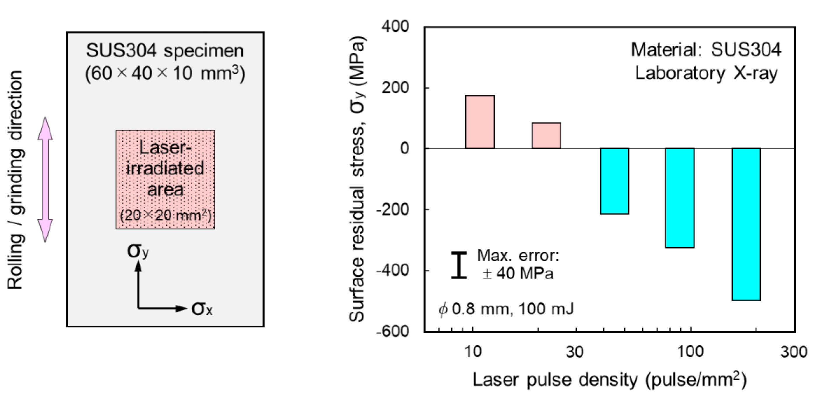
3.1. Preparation of Specimens

To validate the proposed LPwC model, the materials used were HT1000 (1000 MPa grade high tensile strength steel) and SUS304 (type 304 austenitic stainless steel). HT1000 has fine grains of around 10 μm or less and is therefore suitable for the precise measurement of RSs in a small area by XRD with a micro X-ray beam. As a result, HT1000 was used to obtain RS profiles across laser-irradiated spots and lines using synchrotron radiation (SR) as the X-ray source [25]. SUS304 is widely used in various applications; however, it has relatively coarse grains. Thus, SUS304 was used to evaluate the average RS over a specific area with the laboratory X-ray source.
HT1000 specimens with dimensions of 28 × 30 × 17 mm3 were annealed at 973 K for 3 h, followed by furnace cooling to relieve RSs by machining. RSs on the top surface after annealing were close to zero (0–50 MPa). SUS304 specimens with dimensions of 40 × 60 × 10 mm3 were prepared from an SUS304 plate that had been 20% cold-worked by rolling. The SUS304 specimens were ground parallel to the rolling direction to create tensile stresses in the near-surface layer prior to the laser irradiation. The mechanical properties of HT1000 and SUS304 are summarized in Table 3.

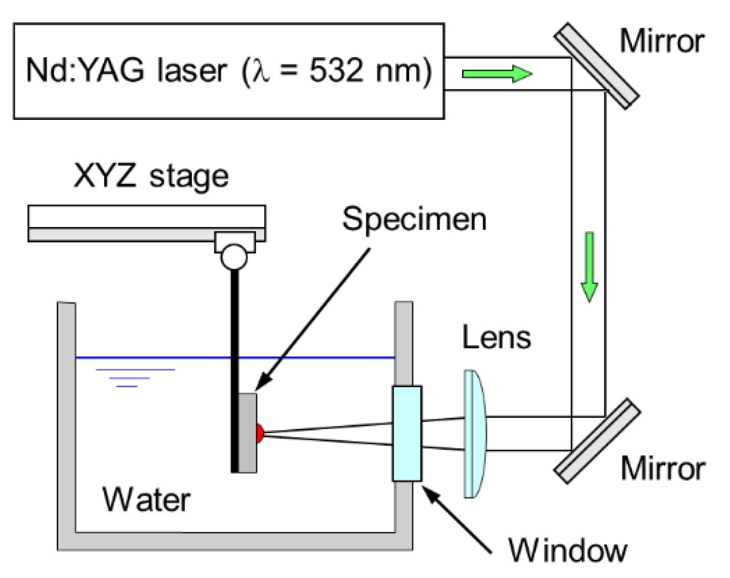
3.2. Setup of Laser Irradiation Experiment

Figure 1 shows a schematic of the experimental setup for laser irradiation of the specimen [12,13]. Laser pulses from a Q-switched and frequency-doubled Nd:YAG laser (λ = 532 nm) irradiated a specimen underwater through an optical window. For the 1D line and 2D area irradiations, the specimen was driven by a tri-axial stage during laser irradiation, while it was fixed for 0D single pulse irradiation. The position, density, and pattern of laser irradiation of the specimen were controlled by the tri-axial stage. The temporal profile of the laser pulse was near-Gaussian and the pulse duration was 5–8 ns at full width-half maximum (FWHM), which was measured with a fast-responding photodiode and fed back along with other parameters to calculate the power density, etc., in each experiment.

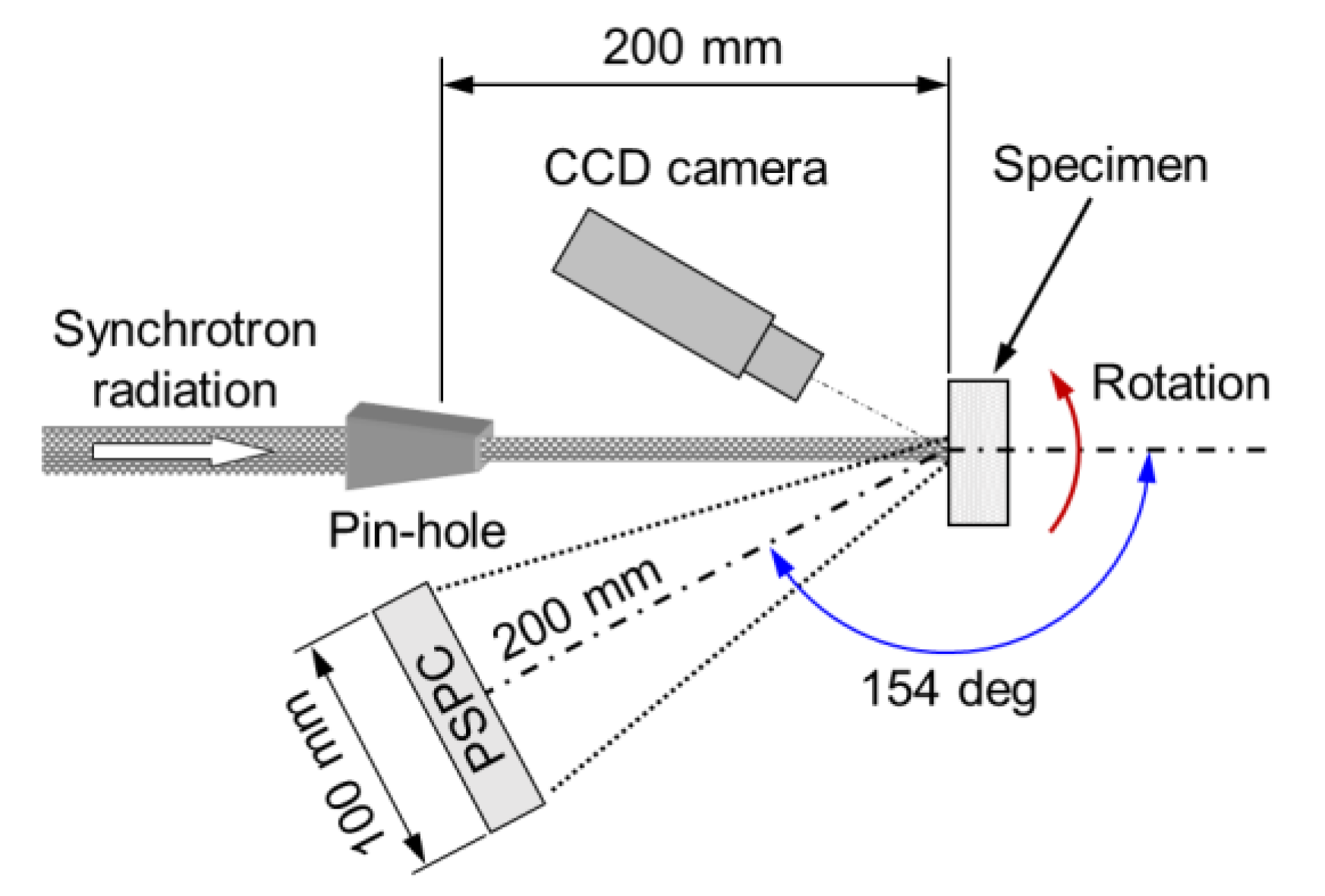
3.3. Residual Stress Measurement by X-Ray Diffraction

To validate the phenomenological model of LPwC proposed in Section 2, RSs on the top surface were measured across spots (0D), lines (1D), and areas (2D) after laser irradiation. The RSs were estimated using the 2θ-sin2ψ XRD method with SR at the Photon Factory (PF) of the High Energy Accelerator Research Organization (KEK). For measurement of the average RS over a specific area, laboratory Mn-kα X-rays were used.
The parameters used in the XRD measurements are listed in Table 4. At KEK-PF, X-rays from beam line BL-3A, with an energy of 5.4 keV, were collimated to 0.2 mm in diameter with a pin-hole and irradiated the HT1000 specimen placed at the center of a goniometer, as shown in Figure 2. The α-Fe (211) was selected as the diffraction plane, considering the intensity and 2θ angle of diffracted X-rays, and detected by a handmade position-sensitive proportional counter (PSPC).

4. Results and Discussion

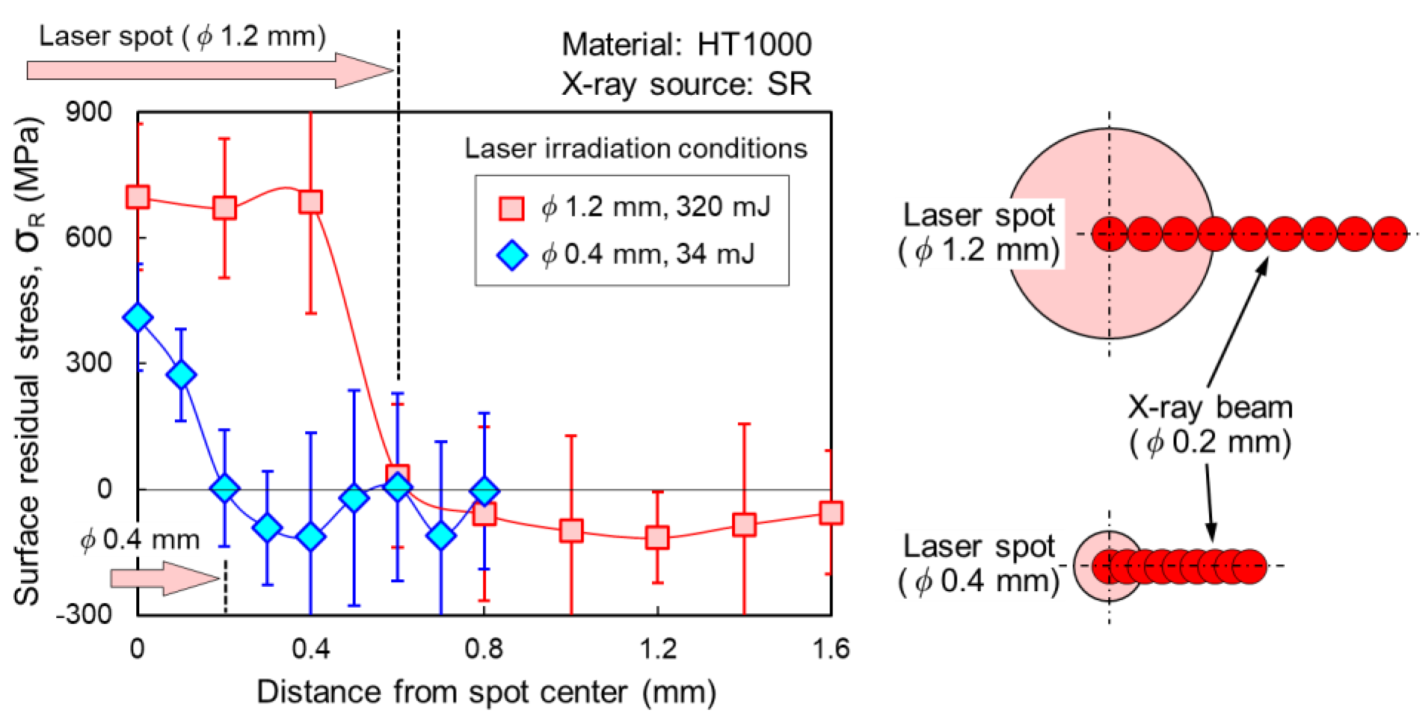
4.1. Surface Residual Stress after 0D Single Pulse Irradiation

A single laser pulse irradiated the HT1000 specimen with a spot diameter of 1.2 mm and an energy of 320 mJ. A pulse with a smaller spot size of 0.4 mm and energy of 34 mJ was also used to determine the effect of spot size; the power density was 4 GW/cm2 for both irradiations. The resultant surface RSs were estimated by XRD with SR.
The RSs in the radial direction across the laser spots are plotted in Figure 3. The error bars in the plot correspond to the standard deviation in the RS estimation. Tensile components exist in the spots, which are attributed to shrinkage of the top surface following heating by the laser pulse. The absolute value of the tensile components decreases drastically with a reduction in spot size. This suggests that a reduction of the laser-irradiated area would enhance the cooling of the top surface, even if the laser power density is constant. Meanwhile, compressive components were observed outside the spots, as predicted by the model in Table 1. The range of compression outside the spot would be comparable to the spot diameter.
In real-world applications, each point on the specimen would typically experience several tens of hits by laser pulses [22,23,24]. In such cases, compression outside the spot would likely accumulate and reach a higher absolute value as laser pulses irradiate the area close to the point of interest. To confirm this, we performed experiments where multiple laser pulses irradiated the same area.
Laser pulses irradiated the HT1000 specimen fixed underwater with 215 mJ pulse energy, 1.0 mm spot diameter, 4 GW/cm2 power density, and 1, 4, 10, or 40 laser pulses on the same spot. The results are shown in Figure 4; the overall RS distribution shifts to the compressive side as the number of pulses increases. It is worth noting that even RSs in the laser spot shifted to the compressive side, despite the pulses resetting the surface RSs each time due to the melting of the surface. If the area around the spot is already in compression, the tensile strain due to solidification after laser irradiation may be offset to some extent by the existing compressive strain. In such cases, the tension in the spot may be reduced and it calls for further investigation.

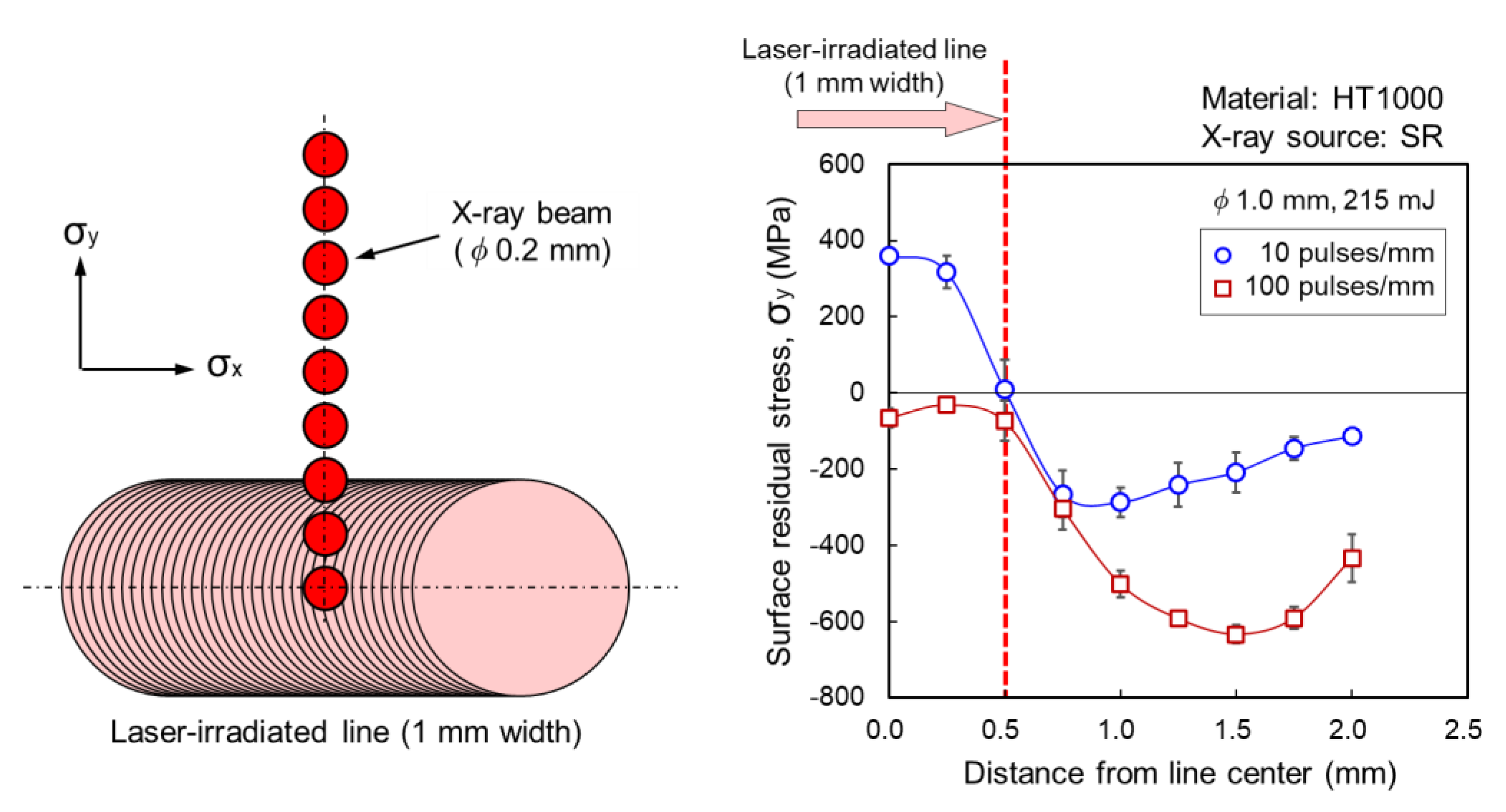
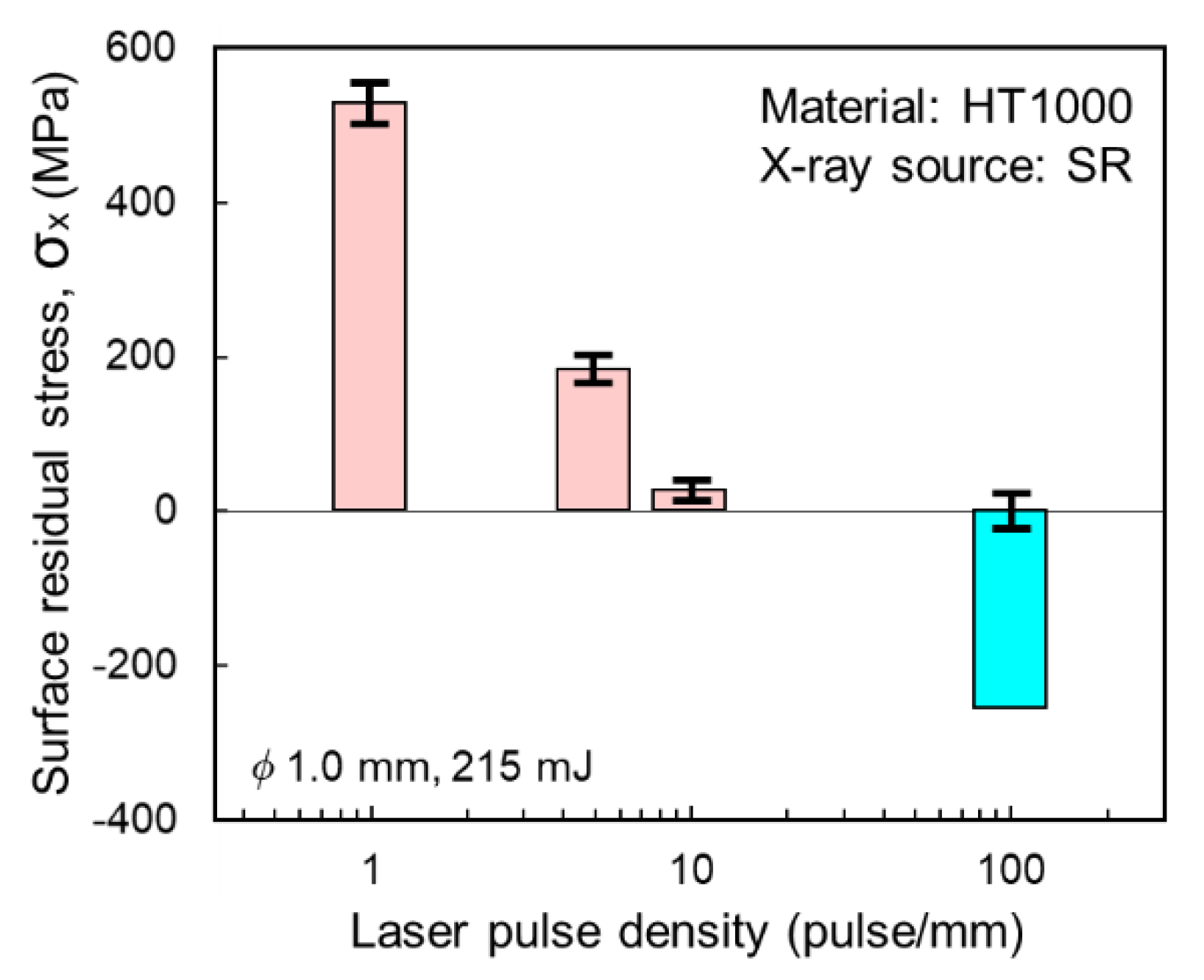
4.2. Surface Residual Stress after 1D Line Irradiation

Inspired by the results shown in Figure 4, we proceeded to 1D line irradiation of the HT1000 specimen using a pulse energy of 215 mJ, spot diameter of 1.0 mm, and power density of 4 GW/cm2. The effects of pulse densities of 1, 5, 10, and 100 pulses/mm on the RS profile were determined. Figure 5 plots the surface RSs in the y-direction (perpendicular to the laser-irradiated lines) for pulse densities of 10 and 100 pulse/mm. As expected, the RS profile of the 100 pulse/mm line has a much lower RS distribution on the compression side compared to the 10 pulse/mm line. The compression outside the laser-irradiated lines exceeds the line width of 1 mm for both lines of 10 and 100 pulse/mm. These results are consistent with those obtained after multiple irradiations of the same spot, as described in Section 4.1 and Figure 4.
The surface RSs in the x-direction (parallel to the laser-irradiated lines) were measured at the center of the laser irradiated lines. The results are plotted in Figure 6 for pulse densities of 1, 5, 10, and 100 pulse/mm. The surface RS changed significantly from tensile to compressive with increasing pulse density, in accordance with the LPwC model described in Table 2 (patterns B and C).

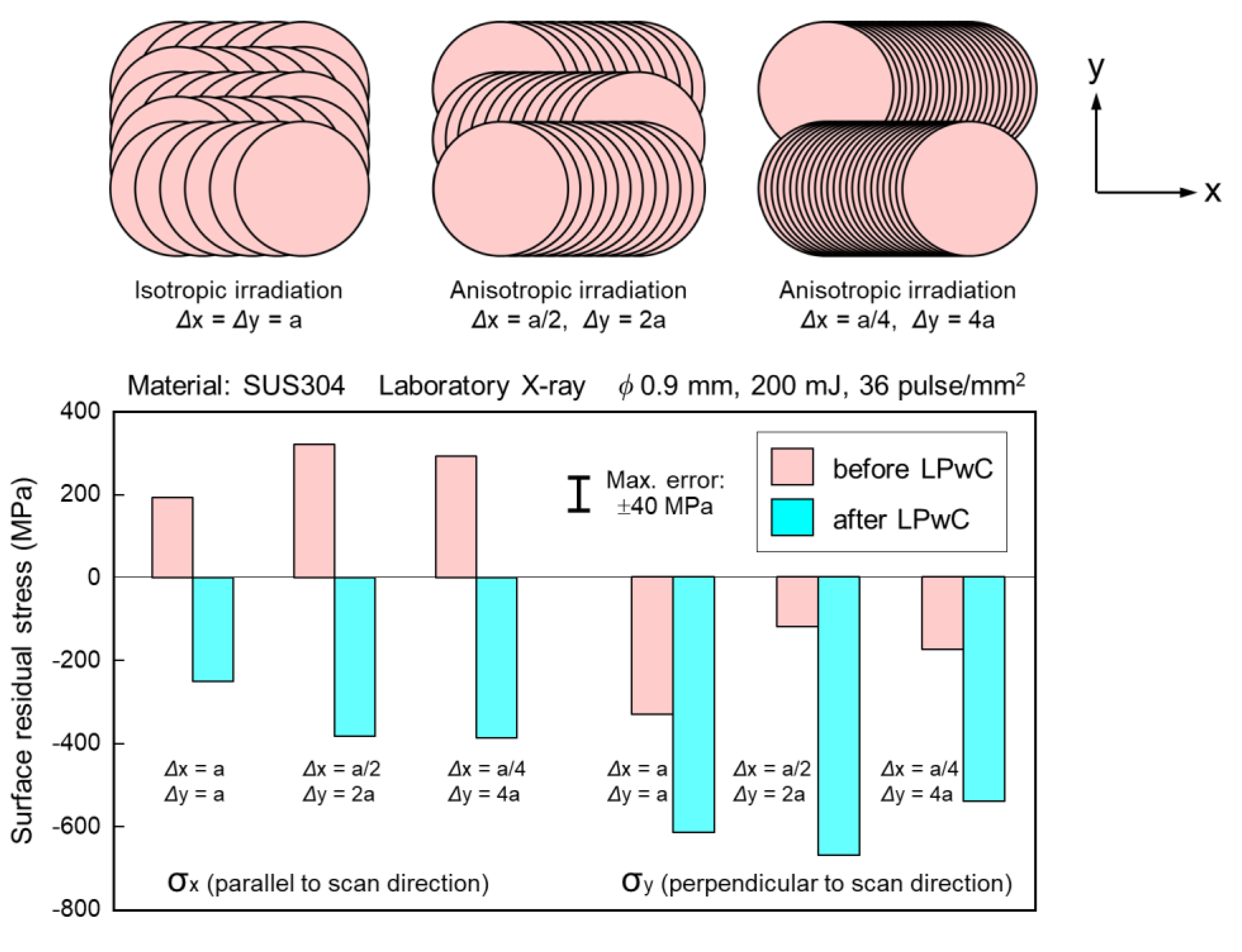
4.3. Surface Residual Stress after 2D Area Irradiation

As demonstrated in the previous sections, the laser pulse irradiation-induced compression around laser-irradiated spots and lines can accumulate with successive irradiations. In this section, we confirm the effect of overlap of neighboring laser pulses on RSs in a 2D area. Laser pulses with an energy of 100 mJ irradiated the SUS304 specimen. The focal spot size was 0.8 mm, and the pulse duration was 5 ns, resulting in a power density of about 4 GW/cm2. The laser pulse density was varied between 11 and 180 pulse/mm2. The surface RSs measured in the y-direction are plotted in Figure 7. For the surface-ground SUS304 specimens, the standard deviation of RS estimation was about 20 MPa and in most cases less than 40 MPa. In accordance with the LPwC model described in Table 2, a significant effect of pulse density on the RSs in the 2D area was seen.
To compare the effects of isotropic and anisotropic irradiation, SUS304 specimens were irradiated using patterns E and F in Table 2. Successive laser pulses with an energy of 200 mJ converged to a diameter of 0.9 mm and irradiated the SUS304 specimen underwater, with a power density of about 4 GW/cm2. The pulse density was set to 36 pulses/mm2, for a coverage (C) of 2300%. The C indicates the average number of laser pulses that irradiated a given point within the laser-irradiated area, and can be calculated by the following equation: C = (πD2/4)⋅ρ, where D is the spot diameter and ρ is the pulse density.
During isotropic irradiation, the interval between the neighboring laser spots was 0.17 mm in both the x- and y-directions, with an irradiation density of 36 pulses/mm2. During anisotropic irradiation, the interval was reduced by 1/2 or 1/4 in the x-direction and increased 2- or 4-fold in the y-direction, with the same pulse density. The patterns of laser irradiation and RSs are shown in Figure 8. As expected from the LPwC model, compressive RSs were observed on the surface with all irradiation patterns. These findings are important when willing to increase the processing speed in real-world applications. With anisotropic irradiation, the motion of an LPwC machine is slower than with isotropic irradiation. The time required for acceleration and deceleration of the machine can be reduced in the anisotropic irradiation, thus increasing the processing speed.

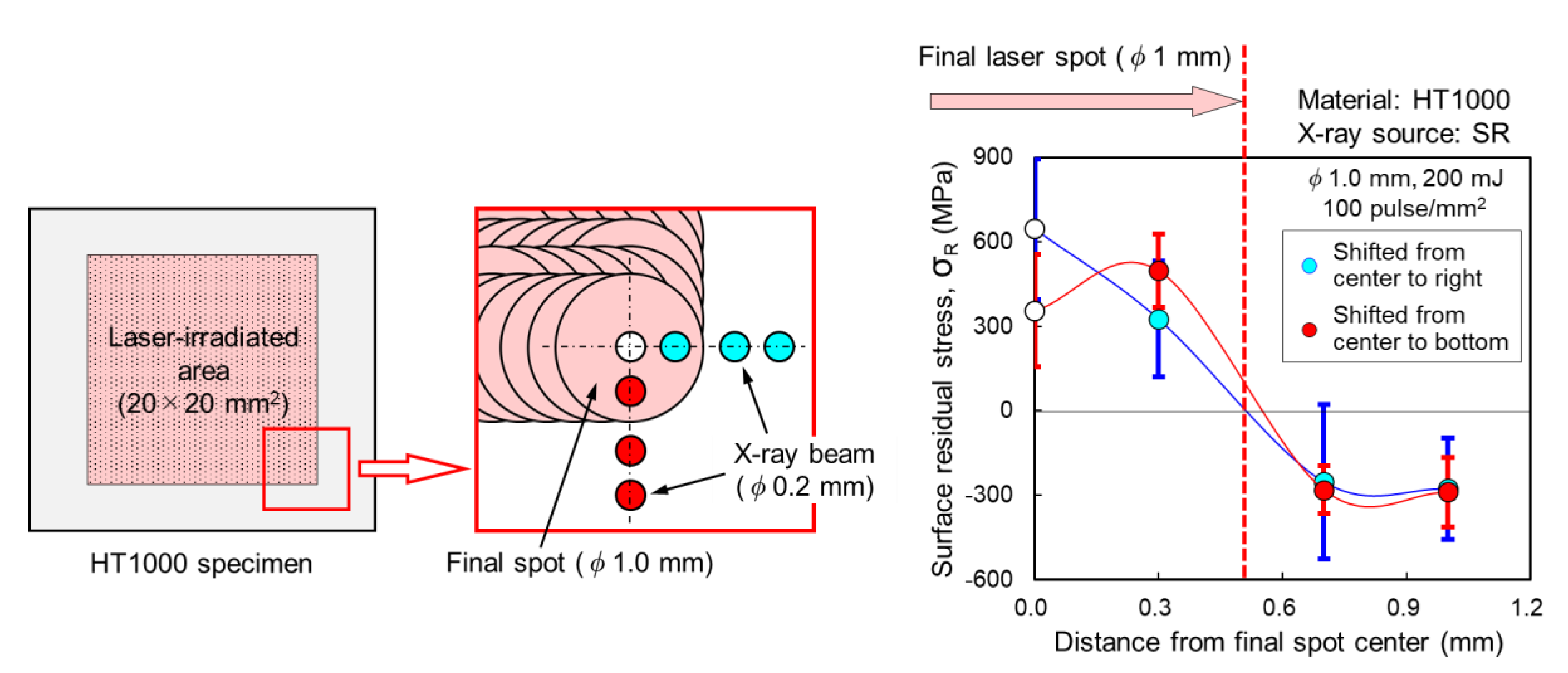
4.4. Surface Residual Stress on the Final Laser-Irradiated Spot in the 2D Area

The results presented in Section 4.1, Section 4.2 and Section 4.3 confirm the validity of the LPwC model described in Table 2, by showing that successive laser pulse irradiation with appropriate overlapping can induce compressive RSs on the surface. Based on the results of the 0D single pulse experiment and the predictions of the LPwC model, the RS state of the final spot should be tensile. To confirm this, we made precise measurements of RSs across the final spot irradiated in the 2D area.
Laser pulses with an energy of 200 mJ were focused to 1.0 mm and irradiated the HT1000 specimen underwater in an isotropic manner (pattern E in Table 2). The power density was 3.2 GW/cm2 and the pulse density was 100 pulses/mm2. The pitch between the neighboring laser spots was 0.1 mm in both the x- and y-directions. The RSs under the final laser spot were estimated by XRD with SR at KEK-PF, as described in Section 3.3.
Figure 9 shows the distributions of RSs in the radial direction across the final spot irradiated in the 2D area. As predicted by the LPwC model, large tensile RSs appeared in the final spot, which was surrounded by a region of compressive RSs. The depth of the tensile region was estimated as less than 10 μm considering thermal diffusion length, L, which could be evaluated from the following equation: L = 2 (Datp)0.5, where Da is the thermal diffusivity and tp is the interaction time between the high-temperature plasma and the top surface. The thermal diffusivity, Da, is in the order of 10 mm2/s for steels. The interaction time, tp, is considered to be no more than 1 μs; the plasma illumination completely disappeared within 1 μs in our experiments [7]. Actually, tensile RSs were observed to a depth of about 10 μm for high-strength steel SHY685 [36] and about 5 μm for SUS304 [8] in our experiments. This was confirmed through electrolytic polishing and XRD.
We were concerned that, if the final spot was inadvertently positioned in an area susceptible to fatigue, SCC, etc., cracks may initiate from it due to the tensile RSs. However, we have not yet observed cracks emanating from the final spot subjected to LPwC. This is likely due to the tensile region being extremely shallow compared to the compressive region beneath the spot (typically 1 mm), and to the width of the surrounding compressive region. However, considering the RS state in the final spot, laser irradiation sequence should be terminated outside areas susceptible to fatigue, SCC, etc.

5. Conclusions

We introduced a phenomenological model of LPwC to assess the thermo-mechanical effect of single pulse (0D) irradiation, and the interaction between successive laser pulses in line (1D) and area (2D) irradiations. The model qualitatively predicts RS states on the top surface after LPwC. To validate the proposed LPwC model, specimens of HT1000 and SUS304 were subjected to 0D, 1D, and 2D irradiation. The RS distributions were evaluated by XRD with SR and a laboratory X-ray source. The experiments revealed that after LPwC, the top surface can become compressive through increasing the overlap between adjacent laser pulses as predicted by the LPwC model. The results obtained in the experiments are summarized as follows:
(1) With 0D single pulse irradiation, large tensile RSs were observed within spots irradiated by the single laser pulse, but compressive RSs appeared in the area outside the spots over a distance comparable to the spot diameters. By increasing the number of pulses irradiating the same area, the compressive state outside the spot was enhanced.
(2) With 1D line irradiation, tensile RSs were observed in the laser-irradiated line in the case of low pulse density. However, the RS state changed from tensile to compressive with increasing pulse density. Outside the laser-irradiated lines, compressive RSs were observed over a distance greater than the line width.
(3) With 2D area irradiation, tensile RSs were observed after irradiation with low pulse density, but, similar to the results obtained with 1D line irradiation, the RS state changed from tensile to compressive with increasing pulse density. Under anisotropic irradiation, compressive RSs close to those observed under isotropic irradiation were obtained, even when the pulse interval was reduced by 1/2 or 1/4 times in the x-direction and increased by 2- or 4-fold in the y-direction.

Author Contributions

Conceptualization, Y.S. and K.A.; methodology, Y.S. and K.A.; investigation, Y.S. and K.A.; resources, K.A.; writing—original draft preparation, Y.S.; writing—review and editing, Y.S., K.A., and T.S.; supervision, Y.S., K.A., and T.S. All authors have read and agreed to the published version of the manuscript.

Funding

This research received no external funding.

Acknowledgments

A part of this work was performed with approval from the Photon Factory Program Advisory Committee of the High-Energy Accelerator Research Organization, Japan (Proposal No. 2003G032).

Conflicts of Interest

The authors declare no conflict of interest.

References

  1. Sano, Y. Quarter century development of laser peening without coating. Metals 2020, 10, 152. [Google Scholar] [CrossRef] [Green Version]
  2. Prabhakaran, S.; Kulkarni, A.; Vasanth, G.; Kalainathan, S.; Shukla, P.; Vasudevan, V. Laser shock peening without coating induced residual stress distribution, wettability characteristics and enhanced pitting corrosion resistance of austenitic stainless steel. Appl. Surf. Sci. 2018, 428, 17–30. [Google Scholar] [CrossRef]
  3. Dhakal, B.; Swaroop, S. Review: Laser shock peening as post welding treatment technique. J. Manuf. Process. 2018, 32, 721–733. [Google Scholar] [CrossRef]
  4. Karthik, D.; Swaroop, S. Influence of laser peening on phase transformation and corrosion resistance of AISI 321 steel. J. Mater. Eng. Perform. 2016, 25, 2642–2650. [Google Scholar] [CrossRef]
  5. Gujba, A.K.; Medraj, M. Laser peening process and its impact on materials properties in comparison with shot peening and ultrasonic impact peening. Materials 2014, 7, 7925–7974. [Google Scholar] [CrossRef] [Green Version]
  6. Trdan, U.; Porro, J.A.; Ocaña, J.L.; Grum, J. Laser shock peening without absorbent coating (LSPwC) effect on 3D surface topography and mechanical properties of 6082-T651 Al alloy. Surf. Coat. Technol. 2012, 208, 109–116. [Google Scholar] [CrossRef] [Green Version]
  7. Sano, Y.; Mukai, N.; Okazaki, K.; Obata, M. Residual stress improvement in metal surface by underwater laser irradiation. Nucl. Instrum. Methods Phys. Res. B 1997, 121, 432–436. [Google Scholar] [CrossRef]
  8. Mukai, N.; Aoki, N.; Obata, M.; Ito, A.; Sano, Y.; Konagai, C. Laser processing for underwater maintenance in nuclear plants. In Proceedings of the 3rd JSME/ASME International Conference on Nuclear Engineering (ICONE-3), Kyoto, Japan, 23–27 April 1995. S404–3. [Google Scholar]
  9. Stress Corrosion Cracking in Light Water Reactors: Good Practices and Lessons Learned; IAEA Nuclear Energy Series No. NP-T-3.13; International Atomic Energy Agency: Vienna, Austria, 2011; Available online: https://www.iaea.org/publications/8671/stress-corrosion-cracking-in-light-water-reactors-good-practices-and-lessons-learned (accessed on 18 June 2020).
  10. Sano, Y.; Obata, M.; Yamamoto, T. Residual stress improvement of weldment by laser peening. Weld. Int. 2006, 20, 598–601. [Google Scholar] [CrossRef]
  11. Sano, Y.; Mukai, N.; Yoda, M.; Ogawa, K.; Suezono, N. Underwater laser shock processing to introduce residual compressive stress on metals. Mater. Sci. Res. Int. 2001, 2, 453–458. [Google Scholar]
  12. Sano, Y.; Kimura, M.; Mukai, N.; Yoda, M.; Obata, M.; Ogisu, T. Process and application of shock compression by nanosecond pulses of frequency-doubled Nd: YAG laser. In Proceedings of the International Forum on Advanced High-Power Lasers and Applications (AHPLA’99), Osaka, Japan, 1–5 November 1999. [Google Scholar]
  13. Sano, Y.; Obata, M.; Kubo, T.; Mukai, N.; Yoda, M.; Masaki, K.; Ochi, Y. Retardation of crack initiation and growth in austenitic stainless steels by laser peening without protective coating. Mater. Sci. Eng. A 2006, 417, 334–340. [Google Scholar] [CrossRef]
  14. Jiao, Y.; He, W.; Shen, X. Enhanced high cycle fatigue resistance of Ti-17 titanium alloy after multiple laser peening without coating. Int. J. Adv. Manuf. Technol. 2019, 104, 1333–1343. [Google Scholar] [CrossRef] [Green Version]
  15. Troiani, E.; Zavatta, N. The effect of laser peening without coating on the fatigue of a 6082-T6 aluminum alloy with a curved notch. Metals 2019, 9, 728. [Google Scholar] [CrossRef] [Green Version]
  16. Ivetic, G.; Meneghin, I.; Troiani, E.; Molinari, G.; Ocaña, J.; Morales, M.; Porro, J.; Lanciotti, A.; Ristori, V.; Polese, C.; et al. Fatigue in laser shock peened open-hole thin aluminium specimens. Mater. Sci. Eng. A 2012, 534, 573–579. [Google Scholar] [CrossRef] [Green Version]
  17. Altenberger, I.; Nalla, R.K.; Sano, Y.; Wagner, L.; Ritchie, R.O. On the effect of deep-rolling and laser-peening on the stress-controlled low- and high-cycle fatigue behavior of Ti-6Al-4V at elevated temperatures up to 550 °C. Int. J. Fatigue 2012, 44, 292–302. [Google Scholar] [CrossRef]
  18. Sano, Y.; Masaki, K.; Gushi, T.; Sano, T. Improvement in fatigue performance of friction stir welded A6061-T6 aluminum alloy by laser peening without coating. Mater. Des. 2012, 36, 809–814. [Google Scholar] [CrossRef]
  19. Sakino, Y.; Sano, Y.; Kim, Y.-C. Application of laser peening without coating on steel welded joints. Int. J. Struct. Integr. 2011, 2, 332–344. [Google Scholar] [CrossRef]
  20. Masaki, K.; Ochi, Y.; Matsumura, T.; Sano, Y. Effects of laser peening treatment on high cycle fatigue properties of degassing-processed cast aluminum alloy. Mater. Sci. Eng. A 2007, 468–470, 171–175. [Google Scholar] [CrossRef]
  21. Sims, W.; Elias, V. Laser peening for long term operation. Nucl. Plant J. 2018, 4, 54–56. [Google Scholar]
  22. Sano, Y.; Kimura, M.; Sato, K.; Obata, M.; Sudo, A.; Hamamoto, Y.; Shima, S.; Ichikawa, Y.; Yamazaki, H.; Naruse, M.; et al. Development and application of laser peening system to prevent stress corrosion cracking of reactor core shroud. In Proceedings of the 8th International Conference on Nuclear Engineering (ICONE-8), Baltimore, MD, USA, 2–6 April 2000. [Google Scholar]
  23. Yoda, M.; Chida, I.; Okada, S.; Ochiai, M.; Sano, Y.; Mukai, N.; Komotori, G.; Saeki, R.; Takagi, T.; Sugihara, M.; et al. Development and application of laser peening system for PWR power plants. In Proceedings of the 14th International Conference on Nuclear Engineering (ICONE-14), Miami, FL, USA, 17–20 July 2006. [Google Scholar]
  24. Chida, I.; Hirota, K.; Sano, Y.; Sasaki, H.; Sumiya, R.; Inukai, T.; Murakami, I.; Nomura, H. Development of laser peening technology for low pressure turbine blades, In Proceedings of the 19th International Conference on Nuclear Engineering (ICONE-19), Osaka, Japan, 24–25 October 2011.
  25. Akita, K.; Sano, Y.; Takahashi, K.; Tanaka, H.; Ohya, S. Strengthening of Si3N4 ceramics by laser peening. Mater. Sci. Forum 2006, 524–525, 141–146. [Google Scholar] [CrossRef]
  26. Sano, Y.; Akita, K. Evidence of surface compression and stability of laser-peened material without coating. SPring-8 Res. Front. 2005, 127–128. Available online: http://www.spring8.or.jp/pdf/en/res_fro/05/127-128pdf (accessed on 18 June 2020).
  27. Ding, K.; Ye, L. Laser shock peening. In Woodhead Publishing in Materials; Woodhead: Cambridge, UK, 2006. [Google Scholar]
  28. Peyre, P.; Berthe, L.; Scherpereel, X.; Fabbro, R. Laser-shock processing of aluminium-coated 55C1 steel in water-confinement regime, characterization and application to high-cycle fatigue behavior. J. Mater. Sci. 1998, 33, 1421–1429. [Google Scholar] [CrossRef]
  29. Peyre, P.; Chaieb, I.; Braham, C. FEM calculation of residual stresses induced by laser shock processing in stainless steels. Model. Simul. Mater. Sci. Eng. 2007, 15, 205–221. [Google Scholar] [CrossRef]
  30. Kruusing, A. Underwater and water-assisted laser processing: Part 1-General features, steam cleaning and shock processing. Opt. Lasers Eng. 2004, 41, 307–327. [Google Scholar] [CrossRef]
  31. Fabbro, R.; Peyre, P.; Berthe, L.; Scherpereel, X. Physics and applications of laser-shock processing. J. Laser Appl. 1998, 10, 265–279. [Google Scholar] [CrossRef]
  32. Clauer, A.; Lahrman, D. Laser shock processing as a surface enhancement process. Key Eng. Mater. 2001, 197, 121–144. [Google Scholar] [CrossRef]
  33. Ocaña, J.L.; Morales, M.; Molpeceres, C.; Torres, J. Numerical simulation of surface deformation and residual stresses fields in laser shock processing experiments. Appl. Surf. Sci. 2004, 238, 242–248. [Google Scholar] [CrossRef]
  34. Morales, M.; Porro, J.A.; Molpeceres, C.; Holgado, M.; Ocaña, J.L. Analysis of plasma thermal surface effects on the residual stress field induced by LSP in Al2024-t351. J. Optoelectron. Adv. Mater. 2010, 12, 718–722. [Google Scholar]
  35. Measurement of Three-Dimensional Residual Stress Distribution in Single Laser Pulse Irradiated Area. Available online: http://www.spring8.or.jp/pdf/en/user_ex_repo/03B/237.pdf (accessed on 31 May 2020).
  36. Sato, M.; Sano, Y.; Kajiwara, K.; Tanaka, H.; Akita, K. Non-destructive measurement of residual stress depth profile in a laser-peened steel at SPring-8, Proc. In Proceedings of the 9th International Conference on Synchrotron Radiation Instrumentation (SRI 2006), Daegu, Korea, 28 May–3 June 2006. Paper No. 21030023. [Google Scholar]
Figure 1. Experimental setup for underwater laser irradiation.
Metals 10 00816 g001
Figure 2. The XRD with synchrotron radiation setup at the Photon Factory (PF).
Metals 10 00816 g002
Figure 3. Surface RS profiles across laser spots after single pulse irradiation.
Metals 10 00816 g003
Figure 4. Surface RS distribution by distance from laser spot center.
Metals 10 00816 g004
Figure 5. Profiles of surface RS in the y-direction across laser-irradiated lines.
Metals 10 00816 g005
Figure 6. Surface RSs in the x-direction at the center of laser-irradiated lines.
Metals 10 00816 g006
Figure 7. Surface RSs in the y-direction of areas irradiated with lasers differing in pulse density.
Metals 10 00816 g007
Figure 8. Surface RSs before and after area isotropic and anisotropic irradiation.
Metals 10 00816 g008
Figure 9. Surface RS distribution across the final spot irradiated in the 2D area.
Metals 10 00816 g009
Table 1. Time evolution of the surface stress state of a laser-irradiated spot. Blue and red colors represent compression and tension, respectively.
Event over TimeStress State under SpotStress State of RimSchematic Figure
Metals 10 00816 i001During laser irradiation
(typically
≲100 ns)
Expansion of surface under laser spot, generation of plasmaCompressive due to expansion and constraint from surrounding materialCompressive due to thermal expansion under laser spot Metals 10 00816 i002
Melting of surface under laser spotZero stress due to meltingCompressive with decreased amplitude due to melting under spot Metals 10 00816 i003
After laser irradiation
(≳100 ns)
Dissipation of plasma, cooling of surface under laser spotTensile due to shrinkage as cooling proceedsCompressive with further decreased amplitude due to shrinkage under spot Metals 10 00816 i004
Table 2. Surface residual stress after 0D single pulse, 1D line, and 2D area irradiation with different overlaps. Blue and red colors represent compression and tension, respectively.
Pattern of IrradiationResidual Stress (RS) StateSchematic of RS State
A0D (zero-dimensional) single pulse irradiationTensile RS under laser spot. Compressive RS on rim Metals 10 00816 i005
B1D irradiation with sparse overlapWipeout of tensile RS is not sufficient. Average RS must be tensile Metals 10 00816 i006
C1D irradiation with dense overlapWipeout of tensile RS is sufficient. Compressive except under final spot Metals 10 00816 i007
D2D irradiation with sparse overlap (scan direction: X)Wipeout of tensile RS is not sufficient. Average RS must be tensile Metals 10 00816 i008
E2D irradiation with dense overlap (scan direction: X)Wipeout of tensile RS is sufficient. Compressive except under final spot Metals 10 00816 i009
F2D irradiation with dense overlap in X, sparse in Y (scan direction: X)Equivalent to multiple laws of 1D irradiation. Compressive except under final spot of each line Metals 10 00816 i010
G2D irradiation with sparse overlap in X, dense in Y (scan direction: Y)Equivalent to multiple laws of 1D irradiation. Compressive except under spots of the final line Metals 10 00816 i011
Table 3. Mechanical properties of HT1000 and SUS304.
Material0.2 % Proof StressTensile Strength
HT1000983 MPa1063 MPa
SUS304 (20% cold-worked)725 MPa946 MPa
Table 4. Conditions and parameters for residual stress (RS) measurement by XRD.
ParameterLab X-rayKEK-PF
X-ray sourceMn-kαSynchrotron
X-ray energy5.9 keV5.4 keV
X-ray wavelength0.210 nm0.228 nm
X-ray beam sizeφ 3 mmφ 0.2 mm
Diffraction planeγ-Fe311α-Fe211
Diffraction angle152 deg154 deg

