On the Application of Bipolar Electrochemistry to Characterise the Localised Corrosion Behaviour of Type 420 Ferritic Stainless Steel


Abstract
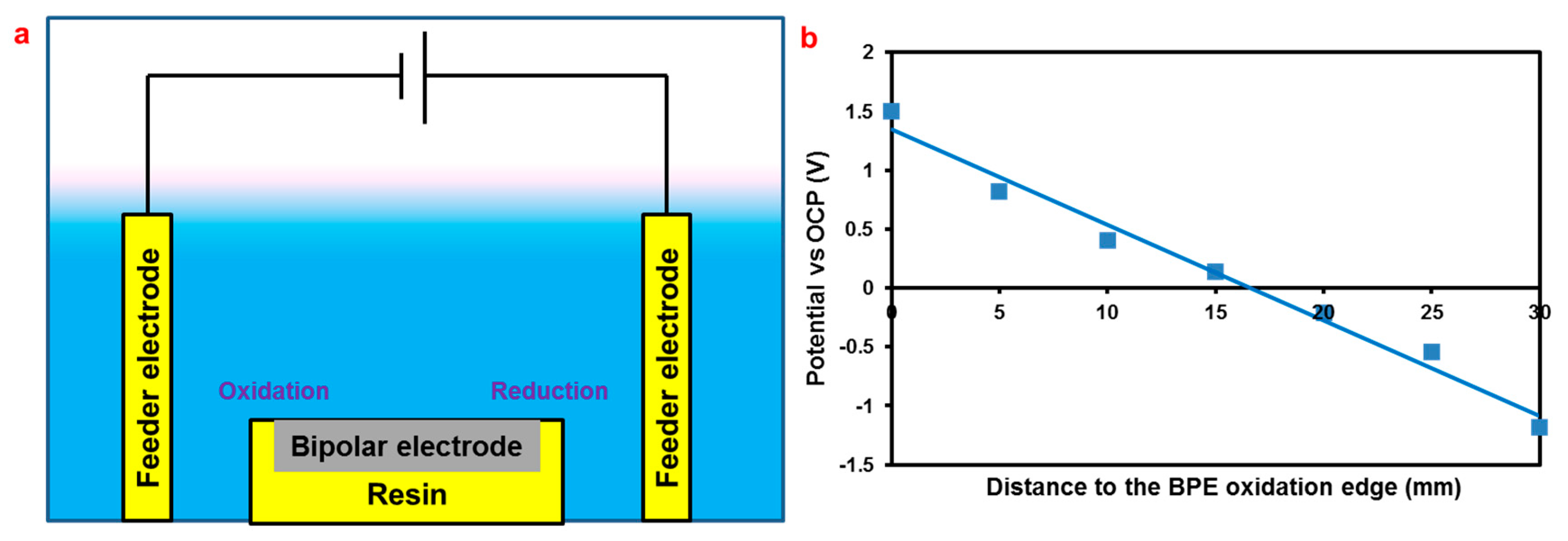
1. Introduction
2. Materials and Experimental Methods
3. Results and Discussion
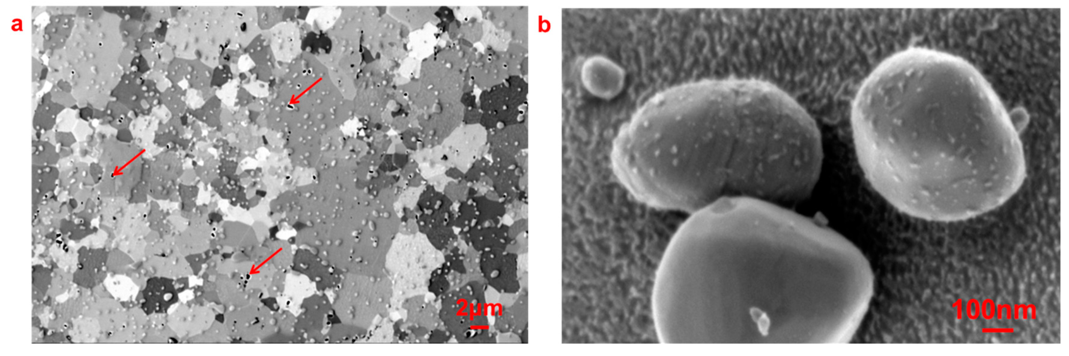
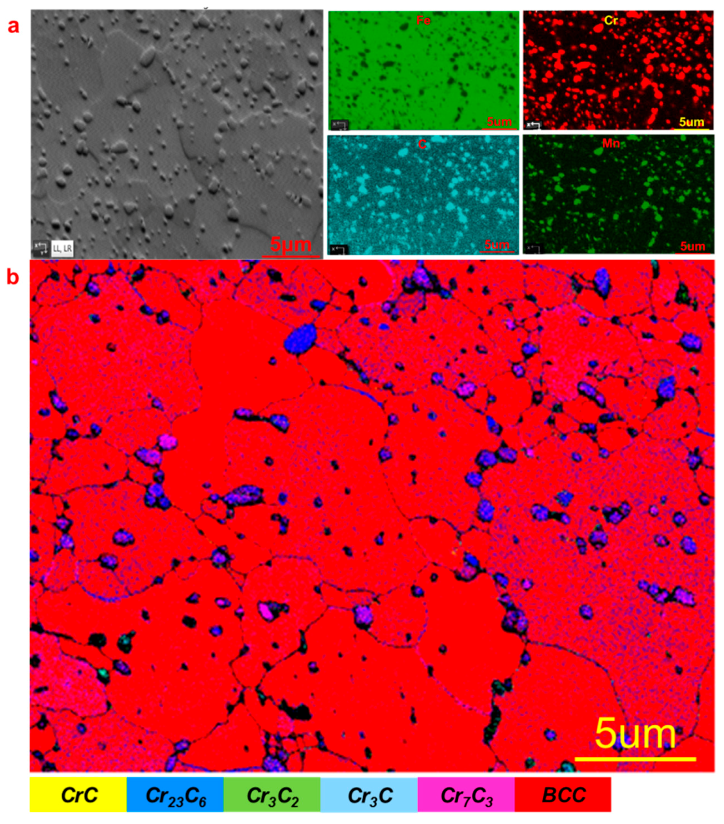
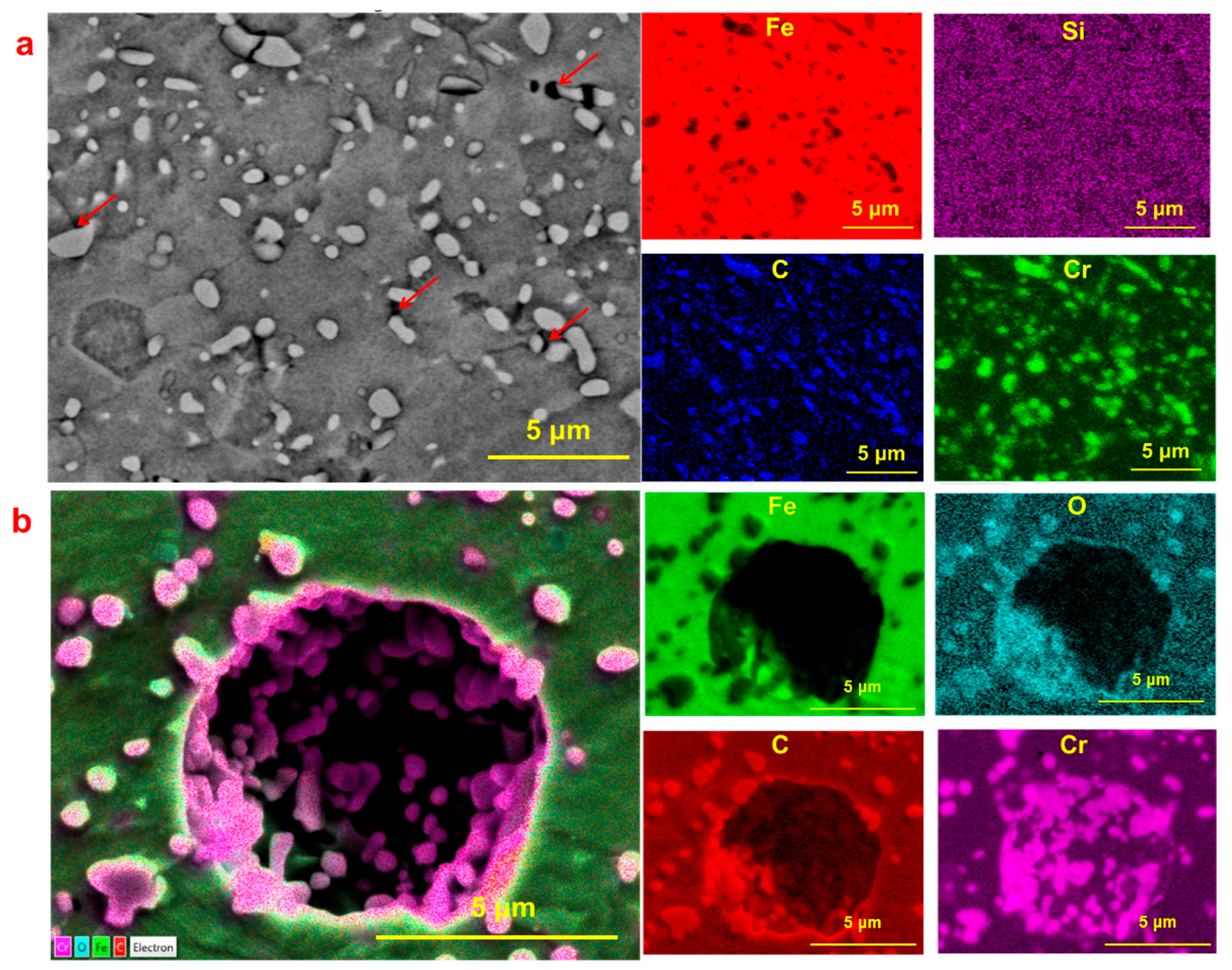
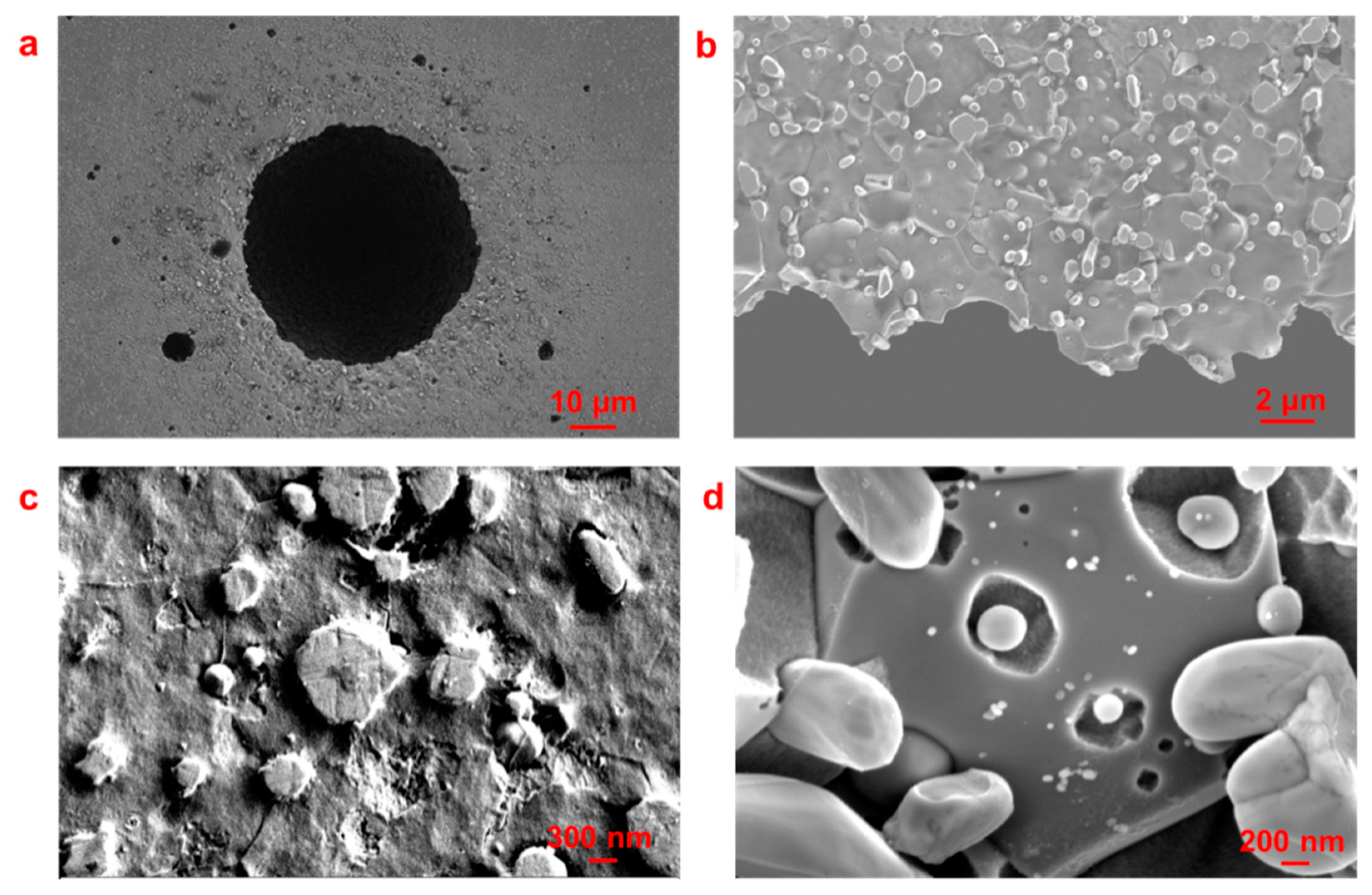
3.1. Pit Nucleation Sites
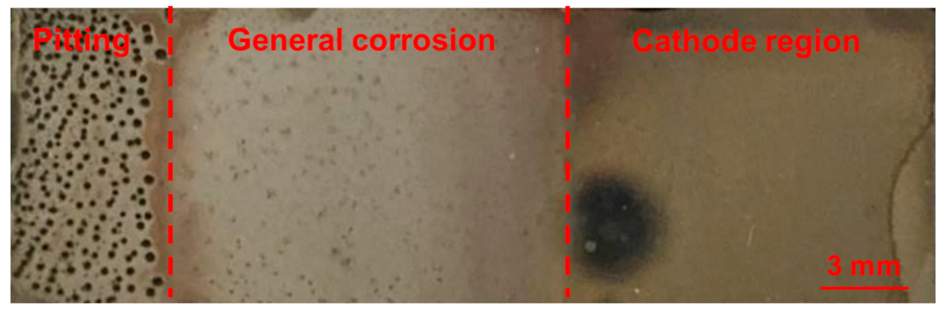
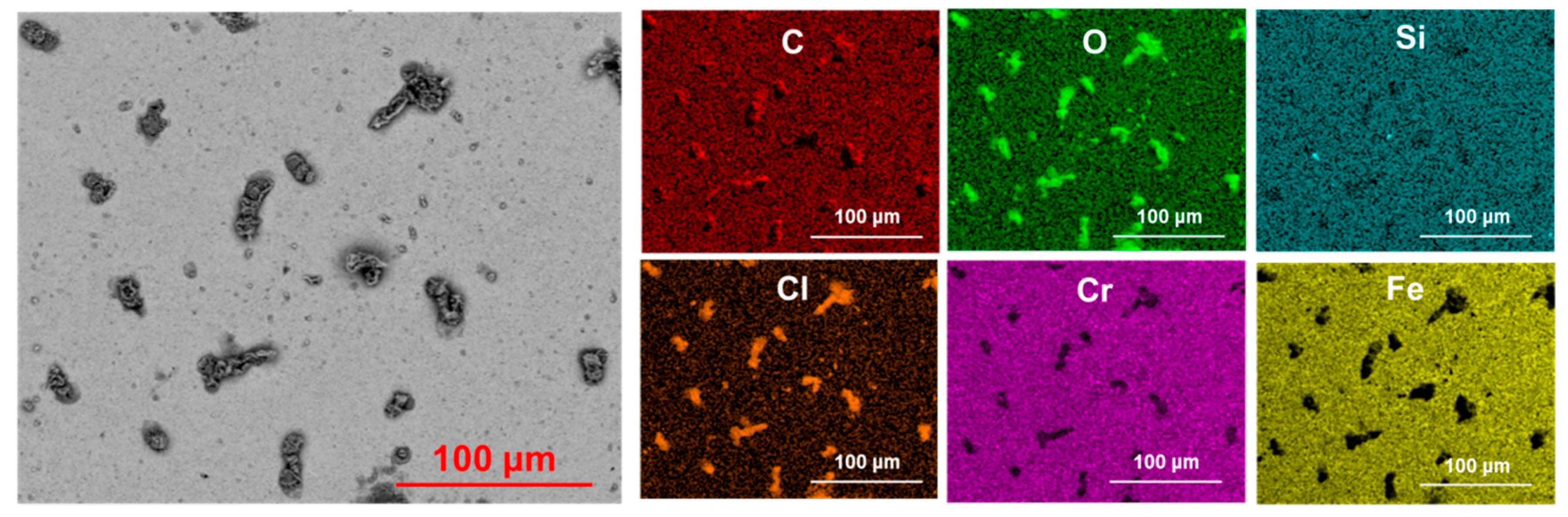
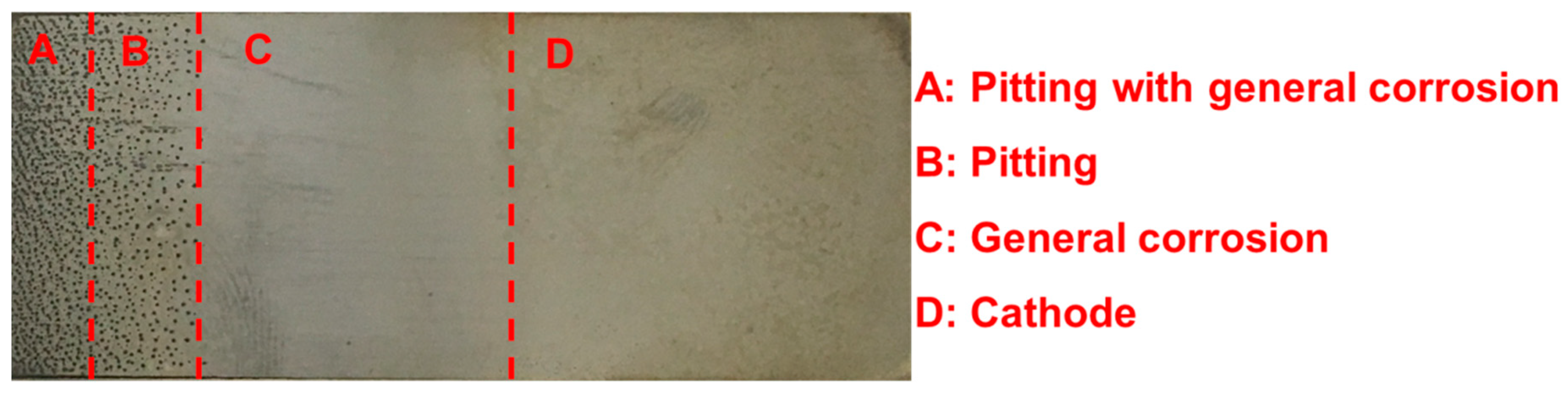
3.2. General Corrosion Behaviour
3.3. Pitting Corrosion Kinetics
4. Conclusions
- (1)
- Bipolar electrochemistry allows a broad range of corrosion responses to be observed in a single experiment.
- (2)
- Cr23C6, Cr3C2, and Cr7C3 are present in Type 420 stainless steel, with pits nucleating near these chromium-rich carbides.
- (3)
- Pit nucleation, growth, and coalescence have been observed.
- (4)
- Pit growth kinetics are independent of the acting potential.
- (5)
- A critical pit volume for the transition from metastable to stable pits has been determined.
Author Contributions
Funding
Conflicts of Interest
References
- Zhou, Y.; Engelberg, D.L. Application of a modified bi-polar electrochemistry approach to determine pitting corrosion characteristics. Electrochem. Commun. 2018, 93, 158–161. [Google Scholar] [CrossRef]
- Munktell, S.; Tydén, M.; Högström, J.; Nyholm, L.; Björefors, F. Bipolar electrochemistry for high-throughput corrosion screening. Electrochem. Commun. 2013, 34, 274–277. [Google Scholar] [CrossRef]
- Pébère, N.; Vivier, V. Local Electrochemical Measurements in Bipolar Experiments for Corrosion Studies. ChemElectroChem 2016, 3, 415–421. [Google Scholar] [CrossRef]
- Crooks, R.M. Principles of Bipolar Electrochemistry. ChemElectroChem 2016, 3, 357–359. [Google Scholar] [CrossRef]
- Wiesener, K.; Ohms, D.; Benczúr-Ürmössy, G.; Berthold, M.; Haschka, F. High power metal hydride bipolar battery. J. Power Sources 1999, 84, 248–258. [Google Scholar] [CrossRef]
- Sequeira, C.A.C.; Cardoso, D.S.P.; Gameiro, M.L.F. Bipolar Electrochemistry, a Focal Point of Future Research. Chem. Eng. Commun. 2016, 203, 1001–1008. [Google Scholar] [CrossRef]
- Qi, Z.; You, S.; Ren, N. Wireless Electrocoagulation in Water Treatment Based on Bipolar Electrochemistry. Electrochim. Acta. 2017, 229, 96–101. [Google Scholar] [CrossRef]
- Yi, Y.; Cho, P.; Al Zaabi, A.; Addad, Y.; Jang, C. Potentiodynamic polarization behaviour of AISI type 316 stainless steel in NaCl solution. Corros. Sci. 2013, 74, 92–97. [Google Scholar] [CrossRef]
- Krawczyk, B.; Cook, P.; Hobbs, J.; Engelberg, D. Corrosion Behavior of Cold Rolled Type 316L Stainless Steel in HCl Containing Environments. Corrosion 2017, 73, 1346. [Google Scholar] [CrossRef]
- Moayed, M.H.; Newman, R.C. Evolution of current transients and morphology of metastable and stable pitting on stainless steel near the critical pitting temperature. Corros. Sci. 2006, 48, 1004–1018. [Google Scholar] [CrossRef]
- Al Saadi, S.; Yi, Y.; Cho, P.; Jang, C.; Beeley, P. Passivity breakdown of 316L stainless steel during potentiodynamic polarization in NaCl solution. Corros. Sci. 2016, 111, 720–727. [Google Scholar] [CrossRef]
- Pistorius, P.C.; Burstein, G.T. Metastable Pitting Corrosion of Stainless Steel and the Transition to Stability. Philos. Trans. R. Soc. A Math. Phys. Eng. Sci. 1992, 341, 531–559. [Google Scholar]
- Laycock, N.J. Metastable Pitting and the Critical Pitting Temperature. J. Electrochem. Soc. 1998, 145, 2622. [Google Scholar] [CrossRef]
- Örnek, C.; Léonard, F.; McDonald, S.A.; Prajapati, A.; Withers, P.J.; Engelberg, D.L. Time-dependent in situ measurement of atmospheric corrosion rates of duplex stainless steel wires. npj Mater. Degrad. 2018, 2, 1–15. [Google Scholar]
- Eguchi, K.; Burnett, T.L.; Engelberg, D.L. X-Ray tomographic characterisation of pitting corrosion in lean duplex stainless steel. Corros. Sci. 2019, 165, 108406. [Google Scholar] [CrossRef]
- Bond, A.P.; Dundas, H.J. Effects of Composition on the Stress Corrosion Cracking of Ferritic Stainless Steels. Corrosion 2013, 24, 344–352. [Google Scholar] [CrossRef]
- Newberg, R.T.; Uhlig, H.H. Stress Corrosion Cracking of 18% Cr Ferritic Stainless Steels. J. Electrochem. Soc. 1972, 119, 981. [Google Scholar] [CrossRef]
- Yin, Z.F.; Wang, X.Z.; Liu, L.; Wu, J.Q.; Zhang, Y.Q. Characterization of corrosion product layers from CO2corrosion of 13Cr stainless steel in simulated oilfield solution. J. Mater. Eng. Perform. 2011, 20, 1330–1335. [Google Scholar] [CrossRef]
- Anantha, K.H.; Örnek, C.; Ejnermark, S.; Medvedeva, A.; Sjöström, J.; Pan, J. In Situ AFM Study of Localized Corrosion Processes of Tempered AISI 420 Martensitic Stainless Steel: Effect of Secondary Hardening. J. Electrochem. Soc. 2017, 164, C810–C818. [Google Scholar] [CrossRef]
- Lei, X.; Feng, Y.; Zhang, J.; Fu, A.; Yin, C.; Macdonald, D.D. Impact of Reversed Austenite on the Pitting Corrosion Behavior of Super 13Cr Martensitic Stainless Steel. Electrochim. Acta. 2016, 191, 640–650. [Google Scholar] [CrossRef]
- Anantha, K.H.; Örnek, C.; Ejnermark, S.; Medvedeva, A.; Sjöström, J.; Pan, J. Correlative Microstructure Analysis and In Situ Corrosion Study of AISI 420 Martensitic Stainless Steel for Plastic Molding Applications. J. Electrochem. Soc. 2017, 164, C85–C93. [Google Scholar] [CrossRef]
- Candelaria, A.F.; Pinedo, C.E. Influence of the heat treatment on the corrosion resistance of the martensitic stainless steel type AISI 420. J. Mater. Sci. Lett. 2003, 22, 1151–1153. [Google Scholar] [CrossRef]
- Nakagawa, H.; Miyazaki, T. Effect of retained austenite on the microstructure and mechanical properties of martensitic precipitation hardening stainless steel. J. Mater. Sci. 1999, 34, 3901–3908. [Google Scholar] [CrossRef]
- de Moor, E.; Lacroix, S.; Clarke, A.J.; Penning, J.; Speer, J.G. Effect of retained austenite stabilized via quench and partitioning on the strain hardening of martensitic steels. Metall. Mater. Trans. A Phys. Metall. Mater. Sci. 2008, 39, 2586–2595. [Google Scholar] [CrossRef]
- Godec, M.; Balantič, D.A.S. Coarsening behaviour of M23C6 carbides in creep-resistant steel exposed to high temperatures. Sci. Rep. 2016, 6, 29734. [Google Scholar] [CrossRef] [PubMed]
- Du Toit, M.; Van Rooyen, G.T.; Smith, D. Heat-affected zone sensitization and stress corrosion cracking behaviour of 12% chromium type 1.4003 ferritic stainless steel. Weld. World 2007, 51, 41–50. [Google Scholar] [CrossRef]
- Bjärbo, A.; Hättestrand, M. Complex carbide growth, dissolution, and coarsening in a modified 12 pet chromium steel-an experimental and theoretical study. Metall. Mater. Trans. A Phys. Metall. Mater. Sci. 2001, 32, 19–27. [Google Scholar] [CrossRef]
- Gellings, P.J.; de Jongh, M.A. Grain boundary oxidation and the chromium-depletion theory of intercrystalline corrosion of austenitic stainless steels. Corros. Sci. 1967, 7, 413–421. [Google Scholar] [CrossRef]
- Jung, K.; Oh, K.; Nam, D.H.; Ahn, S.; Oh, S.; Kwon, H. Effects of Centerline Segregation of Cr Carbides and Non-Metallic Inclusions on the Pitting Corrosion of Fe-13Cr-0.3C Stainless Steel Produced by Continuous Casting and Strip Casting. Corrosion 2017, 73, 979–987. [Google Scholar] [CrossRef]
- Frankel, G.S.; Stockert, L.; Hunkeler, F.; Boehni, H. Metastable pitting of stainless steel. Corrosion 1987, 43, 429–436. [Google Scholar] [CrossRef]
- Liu, J.; Wong, L.M.; Wong, L.H.; Chiam, S.Y.; Li, S.F.; Ren, Y. Immobilization of dye pollutants on iron hydroxide coated substrates: kinetics, efficiency and the adsorption mechanism. J. Mater. Chem. A 2016, 4, 13280–13288. [Google Scholar] [CrossRef]
- N Dai, N.; Zhang, J.; Chen, Q.; Yi, B.; Cao, F.; Zhang, J. Effect of the direct current electric field on the initial corrosion of steel in simulated industrial atmospheric environment. Corros. Sci. 2015, 99, 295–303. [Google Scholar] [CrossRef]
- Asami, K.; Kikuchi, M. In-depth distribution of rusts on a plain carbon steel and weathering steels exposed to coastal-industrial atmosphere for 17 years. Corros. Sci. 2003, 45, 2671–2688. [Google Scholar] [CrossRef]
- Hao, L.; Zhang, S.; Dong, J.; Ke, W. Evolution of corrosion of MnCuP weathering steel submitted to wet/dry cyclic tests in a simulated coastal atmosphere. Corros. Sci. 2012, 58, 175–180. [Google Scholar] [CrossRef]
- Stratmann, M.; Bohnenkamp, K.; Ramchandran, T. The influence of copper upon the atmospheric corrosion of iron. Corros. Sci. 1987, 27, 905–926. [Google Scholar] [CrossRef]
- Ignatov, I.; Mosin, O.; Gluhchev, G.; Karadzhov, S.; Miloshev, G.; Ivanov, N. Studying Electrochemically Activated NaCl Solutions of Anolyte and Catholyte by Methods of Non-Equilibrium Energy Spectrum (NES) and Differential Non-Equilibrium Energy Spectrum (DNES). J. Med. Physiol. Biophys. 2016, 20, 13–23. [Google Scholar]
- Duval, J.; Kleijn, J.M.; Van Leeuwen, H.P. Bipolar electrode behaviour of the aluminium surface in a lateral electric field. J. Electroanal. Chem. 2001, 505, 1–11. [Google Scholar] [CrossRef]
- Tian, W.; Li, S.; Du, N.; Chen, S.; Wu, Q. Effects of applied potential on stable pitting of 304 stainless steel. Corros. Sci. 2015, 93, 242–255. [Google Scholar] [CrossRef]
- Ernst, P.; Newman, R.C. Pit growth studies in stainless steel foils I. Introduction and pit growth kinetics. Corros. Sci. 2002, 44, 927–941. [Google Scholar]
- Laycock, N.J.; Krouse, D.P.; Hendy, S.C.; Williams, D.E. Computer Simulation of Pitting Corrosion of Stainless Steels. Electrochem. Soc. Interface 2014, 23, 65–71. [Google Scholar] [CrossRef]


| Phase | A | B | C | Alpha | Beta | Gamma | Space Group | Database |
|---|---|---|---|---|---|---|---|---|
| Fe3C | 5.11 Å | 6.78 Å | 4.54 Å | 90.00° | 90.00° | 90.00° | 62 | HKL |
| Iron bcc | 2.87 Å | 2.87 Å | 2.87 Å | 90.00° | 90.00° | 90.00° | 229 | HKL |
| Cr3C | 5.12 Å | 6.80 Å | 4.58 Å | 90.00° | 90.00° | 90.00° | 62 | ICSD |
| Cr3C2 | 5.53 Å | 11.49 Å | 2.83 Å | 90.00° | 90.00° | 90.00° | 62 | ICSD |
| Cr7C3 | 4.53 Å | 7.01 Å | 12.14 Å | 90.00° | 90.00° | 90.00° | 62 | ICSD |
| Cr23C6 | 10.66 Å | 10.66 Å | 10.66 Å | 90.00° | 90.00° | 90.00° | 225 | ICSD |
| CrC | 4.03 Å | 4.03 Å | 4.03 Å | 90.00° | 90.00° | 90.00° | 225 | ICSD |
© 2020 by the authors. Licensee MDPI, Basel, Switzerland. This article is an open access article distributed under the terms and conditions of the Creative Commons Attribution (CC BY) license (http://creativecommons.org/licenses/by/4.0/).
Share and Cite
Zhou, Y.; Engelberg, D.L. On the Application of Bipolar Electrochemistry to Characterise the Localised Corrosion Behaviour of Type 420 Ferritic Stainless Steel. Metals 2020, 10, 794. https://doi.org/10.3390/met10060794
Zhou Y, Engelberg DL. On the Application of Bipolar Electrochemistry to Characterise the Localised Corrosion Behaviour of Type 420 Ferritic Stainless Steel. Metals. 2020; 10(6):794. https://doi.org/10.3390/met10060794
Chicago/Turabian StyleZhou, Yiqi, and Dirk Lars Engelberg. 2020. "On the Application of Bipolar Electrochemistry to Characterise the Localised Corrosion Behaviour of Type 420 Ferritic Stainless Steel" Metals 10, no. 6: 794. https://doi.org/10.3390/met10060794
APA StyleZhou, Y., & Engelberg, D. L. (2020). On the Application of Bipolar Electrochemistry to Characterise the Localised Corrosion Behaviour of Type 420 Ferritic Stainless Steel. Metals, 10(6), 794. https://doi.org/10.3390/met10060794