Abstract
In this paper, we propose a method of forming a tube into an oblique/curved shape by synchronous multipass spinning, in which the forming roller reciprocates in the radial direction in synchrony with the rotation angle of the spindle while the roller moves back and forth along the workpiece in the axial direction to gradually deform a blank tube into a target shape. The target oblique/curved shape is expressed as a series of inclined circular cross sections. The contact position of the roller and the workpiece is calculated from the inclination angle, center coordinates, and diameter of the cross sections, considering the geometrical shape of the roller. The blank shape and the target shape are interpolated along normalized tool paths to generate the numerical control command of the roller. By this method, we experimentally formed aluminum tubes into curved shapes with various radii of curvature, and the forming accuracy, thickness distribution, and strain distribution are examined. We verified that the curved shapes with the target radii of curvature can be accurately realized.
1. Introduction
Metal spinning is a metal forming process in which a metal tube or sheet is rotated by a motor and pushed by a roller tool to form a target shape. Since the tooling cost of metal spinning is lower than that of press forming, it is effective for small-lot production of many kinds of custom-made products and for product prototyping. Moreover, this process is also applied to mass-produced parts and products such as automobile exhaust parts and stainless-steel bottles. It is also advantageous for manufacturing large metal shells requiring a large die. In addition, there is an advantage that the forming force is small because only the portion where the roller is in contact with is locally deformed; hence, the apparatus size, noise, and vibration are small.
To form products with higher added value, research on noncircular spinning, which can produce noncircular cross-sectional shapes such as an ellipse, eccentricity, and polygon, has advanced in recent years [1,2]. In conventional metal spinning, only products with a circular cross section can be formed, since the forming is performed while rotating the workpiece. If metal spinning can easily form noncircular shapes, which have been manufactured by press forming or sheet metal welding so far, the application of metal spinning will be further expanded.
Formation of exhaust system parts is a typical application of metal spinning in the automotive industry. There is a large demand for a manufacturing method by which the end of a tube is formed into an oblique/curved axis. Irie et al. [3] developed a spinning machine for necking a stainless steel tube into an oblique/curved shape by shifting and tilting the central axis of a blank tube relative to the spindle axis of the planetary forming rollers, which revolve around the workpiece while necking it. Xia and coworkers [4,5] built a finite element model (FEM) simulation of the same process and evaluated the forming force, stress, strain, and thickness distribution. They also spun an oblique shape in experiments and compared the forming force and the thickness distribution with the simulation results.
Another way to form an oblique/curved shape by metal spinning is synchronous spinning, in which the roller moves in synchrony with the workpiece rotation. Amano and Tamura [6] first succeeded in synchronous spinning of an elliptic cone from a steel sheet. They used a mechanical cam, gears, and a lever to drive a roller synchronized with the rotation of a mandrel. Xia et al. [7] proposed a profile driving method in which a three-dimensional cam pushes a forming roller to follow the surface of the product shape and formed various types of noncircular cones. The drawback of mechanical synchronization is lack of flexibility, because it requires a dedicated cam as well as a mandrel for each shape. Numerical control of the forming roller and spindle can realize synchronous spinning more easily without such complicated mechanisms. Shimizu [8] used pulse motors to drive the roller and mandrel to form elliptic and square cones by synchronous spinning. Arai et al. [9] built a CNC spinning machine with the spindle axis driven by a servo motor for synchronous spinning and conducted noncircular tube necking of aluminum tubes.
Sugita and Arai [10] proposed synchronous multipass spinning, which deforms the workpiece gradually in multiple steps from a flat blank to the final shape. This method can form noncircular shapes with vertical walls such as a square cup because the sine law for the wall thickness in shear spinning is not valid in multipass spinning. Härtel and Laue [11] formed a tripod shape with two roller passes while avoiding forming failures by optimization of the forming parameters based on FEM simulation. Music and Allwood [12] developed a spinning machine for noncircular shapes in which the internal rollers were controlled to support the workpiece instead of the mandrels. Russo et al. [13] used the spinning machine of [12] for synchronous multipass spinning of square and elliptic cups without using mandrels. They investigated how the degree of asymmetry of the cross-section shape influences the difficulty of forming and the properties of the formed products.
Regarding the synchronous spinning of an oblique/curved shape, Sekiguchi and Arai [14] proposed a method of controlling the tool position in the radial and axial directions in synchrony with the spindle rotation and experimentally formed oblique/curved shapes from aluminum sheets. In contrast, Han et al. [15] geometrically calculated the contact position of the roller with an oblique cone and moved the roller in the radial direction for synchronous spinning. Sekiguchi and Arai [16] used force control of the roller to push the material onto the inclined mandrel and formed an inclined cone by reciprocating the roller in the axial direction. As the processes described in [14,15,16] involve forming with only one pass and are equivalent to shear spinning, the wall thickness basically follows the sine law. The target shape should be limited to prevent fracture, and vertical walls cannot be formed. Arai and Kanazawa [17] combined this method with multipass spinning, in which the roller reciprocates between the mandrel and the outer edge of the workpiece to deform the workpiece progressively, thereby forming circular and square cups with inclined bottoms from aluminum disks. The position command of the roller is generated by combining the data of a blank disk, the target shape, and the normalized tool paths. Han et al. [18] spun a circular cup with an oblique open end from an offset blank by synchronous multipass spinning. Xiao et al. [19] also used a multipass spinning method to form an angled-flange cylinder from a blank disk.
When the synchronous spinning is performed without a mandrel, the shape of the formed product is completely determined by the roller motion. Therefore, it is necessary to transform the geometrical target shape into the numerical control (NC) program of the roller. In particular, the point of contact between the roller and the target product to form the target shape must be obtained to calculate the tool trajectory. However, the importance of this calculation stage has not been properly recognized so far except in some previous works. Arai [20] applied the synchronous multipass spinning method described in [17] for necking a tube into an oblique/curved shape. In the forming experiment, oblique/curved shapes that were almost the same as the target shape were obtained. On the other hand, the surface of the tube tends to be peeled off owing to friction caused by the side slip of the roller as the roller slides over the workpiece in the axial direction. Since this problem becomes more serious as the tilt angle increases, it is difficult to form a shape with a large inclination angle. Arai [21] utilized a 3D computer aided design (CAD) model in noncircular tube spinning to represent the target shape and calculated the roller contact position using a searching algorithm considering the roller shape geometrically. Although this method can also handle oblique/curved shapes and the spinning of inclined shapes was actually demonstrated in [21], it requires a 3D CAD system to build a target shape model.
In this paper, a synchronous multipass spinning method for oblique/curved tube necking is proposed. The target shape is represented by interpolation of a series of inclined circular cross sections with offsets without using a 3D CAD system. The position where the roller and the product surface come in contact at only one point to form the target shape is calculated by a searching algorithm considering the geometrical shape of the roller. The NC command of the roller is obtained by linear interpolation between the blank shape and the target shape along multiple tool paths, which are normalized in a two-dimensional virtual plane. Since the roller mainly moves in the radial direction in synchrony with the spindle rotation, peeling off of the workpiece surface described in [20] can be prevented. The workpiece is fixed to the spindle and not tilted as in [3,4,5]. It allows for a larger inclination angle and a smaller radius of curvature of the target shapes. Curved shapes with various radii of curvature are formed from aluminum tubes in the experiments by this method. The formed shapes are measured using a laser range sensor to verify the forming accuracy. The thickness distribution and strain distribution of the products are also evaluated.
2. Calculation of Roller Position
The roller motion in the synchronous spinning of a noncircular shape is expressed as three-dimensional data, consisting of the radial position and the axial position of the roller, and the spindle rotation angle. In the case of multipass spinning, the roller trajectory deforms the blank tube into the target shape step by step. The roller should move along the surface of the target shape in the final pass and the roller should move along the blank tube in the initial pass. Thus, the NC commands of the roller trajectory are calculated as follows.
- (1)
- Calculation of the roller contact position with the product with the target shape.
- (2)
- Interpolation of the blank shape and the target shape along the normalized paths.
2.1. Calculation of Roller–Product Contact Position
Since a nonspherical roller is commonly used for a forming tool in metal spinning, it is difficult to analytically solve the contact position between a general oblique/curved product surface and the roller. Therefore, the position where the roller and the target product come in contact at a single point is obtained by a searching algorithm. The target shape is expressed as a series of inclined circles with offset, whose radii, inclination angles, and center coordinates are given individually. Then, the coordinates of a point on the surface of the target shape can be represented by two parameters, the normalized axial distance along the workpiece, , and the circumferential central angle along the cross section, . Here, the roller axial position and the spindle angle are assumed to be fixed, which means that the roller only moves in the radial direction. By varying the parameters and , we obtain the points on the target shape corresponding to each set of parameters. For each of these points, the radial position of the roller when this point is also on the surface of the roller is calculated. Among these positions, the position where the roller is most distant from the spindle axis is the position where the roller and the target product come into contact at only one point.
2.1.1. Expression of Target Shape and Roller Shape
First, a point on the surface of the target shape is expressed by the x, y, z coordinates in the Cartesian coordinate system (Figure 1). The spindle axis of the spinning machine coincides with the z axis, and the radial direction of the roller motion is parallel to the x axis. An oblique/curved shape of a tube with circular cross sections whose centers are on the xz plane is the target shape. In a cross section of the tube with the target shape, the radius of the circle is r, the inclination angle relative to the z axis is , and the center coordinates are . Here, r, , , and are the functions ,, , and of the parameter . and represent both ends of the target shape.
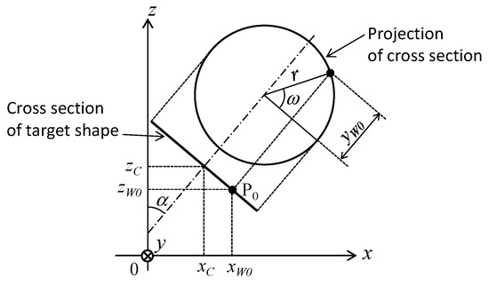
Figure 1.
xyz coordinates of point P0 on a circular cross section of the target shape. The y axis is in the direction into the page.
In practice, the target shape is represented by a series of discrete circular cross sections, and r, , , and can be obtained by interpolation at intermediate positions. When and are respectively assigned to the kth and k + 1th cross sections, the radius r, the inclination angle , and the center coordinates in the intermediate cross section are represented as
The point P0 on the surface of the tube with the target shape corresponding to the central angle is represented as
When the tube with the target shape is rotated around the z axis by an angle , the point P0 moves to P .
The shape of the roller is the outer periphery of a donut-shaped torus of diameter D, with a roundness radius of (Figure 2). The radius of the roundness center R is expressed as . The center of the roller is on the xz plane and the roller axis is parallel to the z axis. Let the coordinates of the roller center Q be . When the point P on the surface of the tube with the target shape is in contact with the roller, the radius of the roller surface at the contact point is
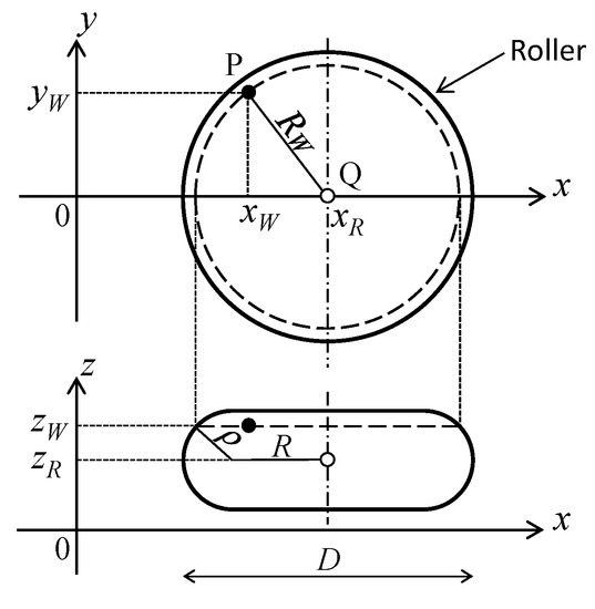
Figure 2.
Position of the center of the roller, Q. Point P on the tube with the target shape is also on the surface of the roller.
At this time, the x coordinate of the roller center Q is expressed as
2.1.2. Search of Contact Position
Then the point of contact between the roller and the target product to form the target shape is searched by the following procedure (Figure 3). The rotation angle of the target shape around the z axis and the position of the roller in the axial direction are given. The parameters and are varied within the range of and , and the corresponding points on the tube with the target shape are obtained from Equations (2) and (3). Then, the radial position of the roller is calculated from Equations (4) and (5). The position where becomes maximum is the position where the target shape and the roller come in contact at a single point. The above search calculation for (,) is repeated while changing the angle of the target shape and the axial position of the roller, and the corresponding radial position of the roller is obtained over the entire surface of the tube with the target shape.
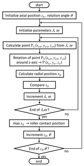
Figure 3.
Computation algorithm for searching the roller contact position with the target shape.
The contact point between the roller and the target shape only exists in considering the thickness of the roller. Moreover, it is not necessary to consider the contact position on the opposite side where the target shape does not face the roller. These limitations can narrow the search range of and . In practice, the incremental step sizes and are assigned to and , respectively. After the maximum value of is obtained in the discretized space of (,) with coarse step sizes, a finer search using smaller step sizes is conducted around the neighborhood of (,) for the former maximum . This algorithm can reduce the total computation time.
2.2. Interpolation of Roller Position
Finally, the roller position during multipass spinning is calculated by interpolation. The roller moves back and forth in the axial direction in synchrony with the spindle rotation to approach the oblique/curved target shape. The computation method in [21] to calculate the NC command from the positions where the roller comes in contact with the product and the blank tube is reviewed here.
The multiple tool paths composed of curved and straight path elements are defined on a virtual two-dimensional plane (Figure 4) to cope with the asymmetry of a noncircular target shape. The virtual plane is normalized from 0 to 1 in the axial direction and radial direction . The components and are used as interpolation coefficients between the target shape and the blank shape. means the tip end of the product and means the base end. When , the roller is on the product surface while the roller is on the blank surface when .
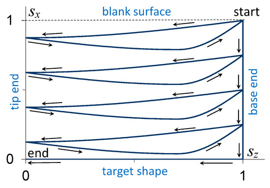
Figure 4.
Example of normalized tool paths. The roller starts from the blank surface of the base end and proceeds to the tip end increasing the radial feed. Then, the roller returns to the base end and the radial feed is increased. This is repeated until and the roller moves along the target shape to the tip end.
The axial and radial positions where the roller touches the product with the target shape are defined as and , respectively, where is the spindle angle. is obtained from as
where is the axial position of the tip end and is that of the base end. The radial position for the blank tube at is also defined as . is constant if the blank is a straight circular tube.
The radial positions, and , are interpolated using as an interpolation coefficient to obtain the intermediate radial position as follows.
Thus, the roller position , is sequentially calculated along the normalized paths to obtain the entire trajectory from the start to the end of the spinning process. The series of roller positions and spindle angles , are executed by NC commands for linear interpolation.
3. Forming Experiments
Using the NC programs generated by the method in Section 2, aluminum tubes were experimentally spun into curved shapes with various radii of curvature. The formed products were scanned by a laser range sensor to verify the dimensional accuracy. The thickness and strain distribution of the products were also examined.
3.1. Experimental Setup
The spinning experiments were conducted using a five-axis CNC spinning machine with two rollers (Figure 5). Each roller was driven by two AC servo motors of 1.3 kW and ball screws of 10 mm lead. The spindle was driven by an AC servo motor of 1.3 kW with a planetary reduction gear. The rollers were made from tool alloy steel (SKD 11) with 88 mm diameter and 4 mm roundness radius. The blank tube of pure aluminum (A 1050 TD-H) had 50 mm diameter and 1.55 mm thickness. The surface of the workpiece and the roller were lubricated using compressor oil (ISO VG 68).
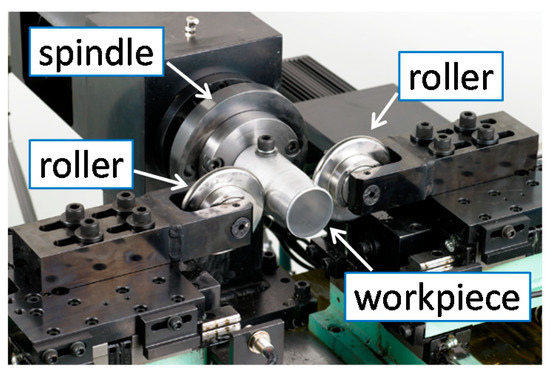
Figure 5.
Five-axis two-roller CNC spinning machine.
3.2. Target Shape
Four types of curved shape with different radii of curvature, samples A, B, C, and D, were formed. The diameter of the necked portion was 30 mm. The radii of curvature of the outer side were (A) 40 mm, (B) 50 mm, (C) 60 mm, and (D) 70 mm, therefore, the radii of curvature of the inner side were (A) 10 mm, (B) 20 mm, (C) 30 mm, and (D) 40 mm, respectively. A cross section in the middle of the curved portion was perpendicular to the spindle axis (α = 0) and its center had an offset of 7 mm from the axis. As described in Section 2.1.1, the curved portion was composed of discrete circular cross sections. The step of inclination angle was 1° and the position of each center was calculated according to the radius of curvature. The maximum inclination angle, , was (A) 64°, (B) 55°, (C) 45°, and (D) 41°.
The calculation algorithm of the contact position of the roller in Section 2.1 was programmed in C language. The contact positions were calculated at 120 points per rotation of the workpiece and every 1 mm in the axial position of the roller. In the case of sample D, 8760 contact positions were calculated in total. The calculations took 12 s using a Windows personal computer (Intel Core i7 CPU, 3.6 GHz).
3.3. Multiple Tool Paths
In the experiments reported in [21], normalized multiple tool paths that were nearly parallel to the axial direction similar to those in Figure 4 were used. Regarding spinning eccentric and oblique shapes, [21] showed that the asymmetry of the radial feed resulted in uneven axial elongation, which depends on the circumferential location. In the case of a small number of paths, the bias of elongation bended the workpiece during the spinning process and it deteriorated the dimensional accuracy.
To solve this problem, a different pattern of normalized paths as shown in Figure 6 was used. Each path element connected between the base side of the target shape and the tip side of the blank. The dimensional error in [21] occurred because the intermediate workpiece was bent beyond the surface of the target shape. The new normalized paths can provide the intermediate workpiece a larger margin to the target shape as the roller approaches the tip end.
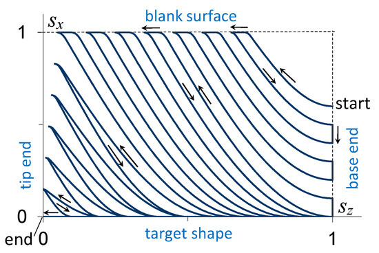
Figure 6.
Normalized tool paths used in the experiments. The roller moves along the curved path elements between the base side of the target shape and the tip side of the blank surface. The radial feed to the target shape increases from the base side to the tip side.
The number of roller passes was 12 roundtrips. The axial roller feed was 2 mm/rev. The final pass along the whole target shape had a 1 mm/rev roller feed. The spindle speed was 30 rpm.
3.4. Mearsurement of Products
Three samples were formed for each type of sample (A, B, C, and D). Two samples were used for shape measurement by the laser sensor. White paint was sprayed on the surface of the spun samples to obtain diffused reflection. A laser range sensor of 0.5 μm resolution was used to measure the shape of each product. To obtain the profiles of the outer curve and inner curve, the surface of the sample was measured every 1 mm in the axial direction. The average values of the two samples were plotted. The circular cross section in the middle of the curved portion, which was perpendicular to the spindle axis, was also measured circumferentially using the laser sensor every 9° of workpiece rotation. From these 40 measurement positions, the offset of the center of the necked portion from the axis was calculated. Also, the distance between the center and each measurement point was calculated, and the average radius and the out of roundness, i.e., the difference between the maximum radius and the minimum radius, were calculated.
The wall thickness and the strain distribution along the outer and inner sides of the curvature were measured using another sample. For the measurement of the axial and circumferential strains, grid lines were scribed on the inner surface of the blank tube before forming. The CNC spinning machine was used to control the position of the L-shaped scriber and the rotation of the blank tube to scribe the marks precisely on the inside of the tube. The line marks parallel to the spindle axis were scribed every 7.5° of rotation of the blank tube. The circumferential marks perpendicular to the axis were scribed every 2.5 mm in the axial direction for samples A and B and every 5 mm for samples C and D. The change in the distance between the marks after the spinning process was measured to calculate the axial and circumferential strains. The samples were cut in the axial direction away from the center of the curve. Then pencil graphite was rubbed into the surface grooves. Transparent adhesive tape was placed on the grid surface, removed, and transferred to paper to obtain a high-resolution image of the grid marks for scanning. The positions of the grid points were identified by the image viewer software to calculate the distance between the marks. The wall thickness of the same cut sample was also measured using a digital micrometer with a dual ball anvil along the outer and inner curves every 5 mm in the axial direction.
4. Results and Discussion
4.1. Dimensional Accuracy
Figure 7 shows a photograph of the formed products of samples A, B, C, and D with different radii of curvature. See Video S1 of the supplementary files. The peeling off of the workpiece surface reported in [20] did not occur. Figure 8a,b show the profiles of the outer and inner sides of the curved portion measured using the laser range sensor. The profiles mostly coincide with those of the target shape (thin solid lines) except that the inner sides near the tip end of samples C and D tend to deviate from the target shape. The root mean square of the deviation from the target shape is plotted in Figure 9. The deviations are 0.08–0.12 mm on the outer side and 0.17–0.32 mm on the inner side.
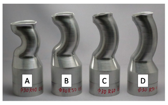
Figure 7.
Formed products of samples A, B, C, and D.
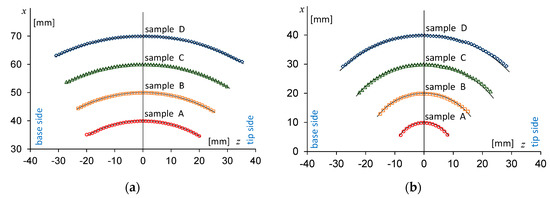
Figure 8.
Profiles of the curved portion of samples A, B, C, and D. (a) Outer and (b) inner sides of the curve. The thin solid lines correspond to target shapes. The horizontal axis represents the axial distance from the middle cross section perpendicular to the spindle axis, in which the base side is negative and the tip side is positive. The origin (0,0) is at the center of each target curvature.
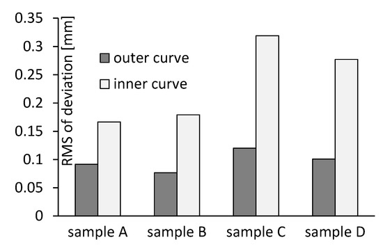
Figure 9.
Root mean square of the deviation from the target shape.
The circular cross sections in the middle of the curved portion, which are perpendicular to the spindle axis, were also measured circumferentially using the laser sensor. Table 1 shows the average radius, the offset from the axis, and the out-of-roundness of each sample. The cross sections have the radius and the offset close to the target values, 15 and 7 mm.

Table 1.
Average radius, offset from the axis, and out-of-roundness of the cross sections perpendicular to the spindle axis.
4.2. Strain Distribution
Figure 10a,b show the distribution of thickness strain along the outer and inner sides of the curved portion of samples A, B, C, and D. The thickness strain was calculated from the measured thickness of the formed products and the blank tube. The thickness strain of the outer side shows a similar tendency for all samples. The wall thickness increases around the middle part and decreases towards the base end. The thickness also decreases towards the tip end to a lesser extent. On the other hand, the thickness of the inner side decreases around the middle of the curved portion. The peak of thinning deviates from the zero position towards the base end. As the radius of the curvature increases, the thinning becomes smaller and the thickness surpasses the blank thickness on the opposite side. The thinning peak moves towards the base end as the curvature radius increases. The actual wall thicknesses were as follows: sample A, 0.90–2.08 mm; sample B, 1.21–2.11 mm; sample C, 1.49–2.09 mm; sample D, 1.65–2.57 mm.
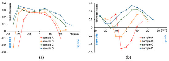
Figure 10.
Distribution of thickness strain in the axial direction. (a) Outer and (b) inner sides of the curve. The horizontal axis represents the distance in the axial direction. The origin of the horizontal axis is at the middle cross section perpendicular to the spindle axis.
Figure 11a,b are plots of the axial strain and the circumferential strain along the outer side of the curved portion. The surface of the outer side shrinks circumferentially and stretches axially. The absolute value of these strains increases towards the tip end. Figure 12a,b show the axial and circumferential strains along the inner side. Although the inner side also shrinks circumferentially and stretches axially, the peak of strain is around the middle cross section. The axial strain at the middle cross section increases as the radius of the curve decreases. This tendency agrees with that of the change in thickness in Figure 10b.
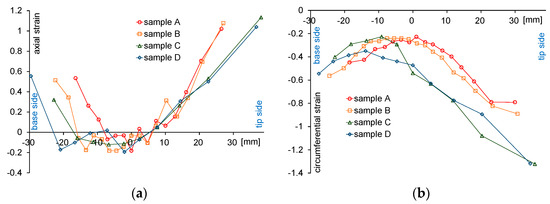
Figure 11.
Distributions of (a) axial strain and (b) circumferential strain in the axial direction of the outer curve. The horizontal axis represents the distance along the curved surface in the axial direction. The origin is at the middle cross section perpendicular to the spindle axis.
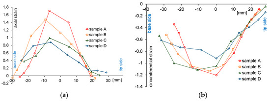
Figure 12.
Distributions of (a) axial strain and (b) circumferential strain in the axial direction of the inner curve. The horizontal axis represents the distance along the curved surface in the axial direction. The origin is at the middle cross section perpendicular to the spindle axis.
4.3. Effect of Normalized Paths
To verify the effect of the new normalized paths in Figure 6, they were compared with simple normalized paths parallel to the spindle axis. Sample B’, which had the same target shape as sample B, was spun using the parallel paths and the dimensional accuracy was measured. Figure 13 shows the actual roller paths for the inner side of the curve after the interpolation described in Section 2.2. Figure 13a shows the actual paths using the parallel normalized paths and Figure 13b shows the actual paths using the new normalized paths. The same axial roller feed and spindle speed were used for both paths.
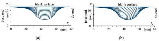
Figure 13.
Actual roller paths for samples (a) B’ and (b) B. and are the positions of the roller in the radial and axial directions. The origin of the horizontal axes is at the base end of the product.
The shapes of the inner curve measured using the laser sensor are plotted in Figure 14. The profile of sample B’ deviates from the target shape near the tip end of the curve. In addition, the roller deviated from the workpiece surface of the inner curve near the tip end while sample B’ was spun. The radial feed of the inner side of the curve was larger than that of the outer side. Then, the inner side elongated more than the outer side, and the tip end of the workpiece was bent towards the outer side beyond the target shape. In contrast, the final roller paths of Figure 13b show less radial feed at the base side and a larger margin to the target shape at the tip side than Figure 13a. Hence, the dimensional error near the tip end was smaller in sample B.
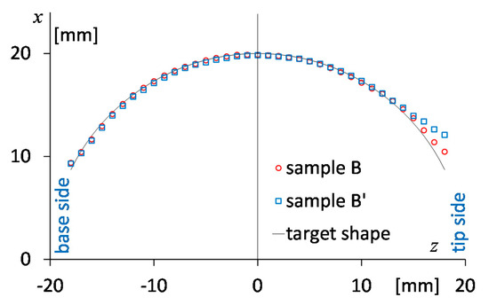
Figure 14.
Profiles of the inner curves of samples B (red) and B’ (blue). The thin solid line corresponds to the target shape. The horizontal axis represents the axial distance from the middle cross section perpendicular to the spindle axis. The origin (0,0) is at the center of the target curvature.
5. Conclusions
The proposed searching algorithm can find the contact position between the roller and the oblique/curved shapes expressed as a series of inclined circular cross sections with offset. The experiments focused on relatively simple curved shapes with cross sections of a constant radius and with a constant curvature. However, more complicated curved shapes of changing radius and curvature can be handled by the same algorithm. It is also easy to calculate the roller contact position with the oblique target shapes of the straight-line profile.
In this study, the position of a point on the surface of the target shape is calculated from the two parameters and using Equations (2) and (3). Here, it is assumed that the center of the circular cross section is on the plane, and the cross sections are rotated around the axis. These equations can be naturally extended to handle more general cases where the center of the cross section has offset in the and directions, and the cross section is inclined around the and axes. Furthermore, the framework of this method is theoretically applicable to an arbitrary tubular surface that can be parametrically expressed as functions of two parameters, e.g., ellipsoids, even if the cross-sectional shape is noncircular.
The experimental results demonstrated that the proposed method can form the curved shapes according to the target shape parameters. A small radius of curvature (10 mm) and a large inclination angle (64°) were achieved in sample A. It is difficult for the spinning machine reported in [3,4,5] to form such a shape because of the mechanical interference between the rollers and the workpiece. Reference [20] showed peeling off of the workpiece surface owing to the side slip of the roller in the normal direction. In contrast, the motion of the roller relative to the workpiece in the proposed method is in the rolling direction of the roller and does not have the side slip. The proposed method prevents the peeling off and hence allows a large inclination angle. Comparison of these two methods can be seen in Videos S2 and S3 of the supplementary files.
Reference [21] suggests that the asymmetry of the radial roller feed resulted in the partial elongation of the workpiece in the axial direction and bending of the workpiece. The improvement of the normalized tool paths as shown in Figure 6 gave the tip side of the intermediate workpiece a larger margin with respect to the target shape. Even when the workpiece is bent, its surface does not go beyond the target profile. The experimental results presented in Figure 14 show the suppression of the dimensional error in the proposed method compared with the previous method. Nevertheless, the error near the tip end is still observed for the new normalized paths of sample B. The deviation from the target profile is also found in samples C and D in Figure 8b. The deviation of the inner curve is larger than that of the outer curve in Figure 9. These dimensional errors may also be attributed to the bending due to the asymmetric radial feed. Further investigation on methods to deal with this problem more generally would be necessary in future work.
Supplementary Materials
The following are available online at https://www.mdpi.com/2075-4701/10/6/733/s1, Video S1: forming process of sample type B by the proposed method. Video S2: peeling off of workpiece surface by the method of Reference [20]. Video S3: spinning of the same shape without peeling off by the proposed method.
Author Contributions
Conceptualization, H.A.; Data curation, S.G.; Formal analysis, S.G.; Investigation, H.A. and S.G.; Methodology, H.A.; Software, H.A.; Validation, S.G.; Writing—original draft, H.A.; Writing—review and editing, H.A. and S.G. All authors have read and agreed to the published version of the manuscript.
Funding
This research received no external funding.
Acknowledgments
The authors wish to thank Shuhei Murakami, Yamagata Research Institute of Technology, for measurement of experimental results.
Conflicts of Interest
The authors declare no conflict of interest.
References
- Music, O.; Allwood, J.M.; Kawai, K. A review of the mechanics of metal spinning. J. Mater. Process. Technol. 2010, 219, 3–23. [Google Scholar] [CrossRef]
- Xia, Q.; Xiao, G.; Long, H.; Cheng, X.; Sheng, X. A review of process advancement of novel metal spinning. Int. J. Mach. Tools Manuf. 2014, 85, 100–121. [Google Scholar] [CrossRef]
- Irie, T. Method and Apparatus for Forming a Processed Portion of a Workpiece. U.S. Patent US6223993B1, 22 May 2001. [Google Scholar]
- Xia, Q.; Cheng, X.; Hu, Y.; Ruan, F. Finite element simulation and experimental investigation on the forming forces of 3D non-axisymmetrical tubes spinning. Int. J. Mech. Sci. 2006, 48, 726–735. [Google Scholar] [CrossRef]
- Xia, Q.; Cheng, X.; Long, H.; Ruan, F. Finite element analysis and experimental investigation on deformation mechanism of non-axisymmetric tube spinning. Int. J. Adv. Manuf. Technol. 2012, 59, 263–272. [Google Scholar] [CrossRef]
- Amano, T.; Tamura, K. The study of an elliptical cone spinning by the trial equipment. In Proceedings of the 3rd International Conference on Rotary Metalworking Processes, Kyoto, Japan, 8–10 September 1984; pp. 213–224. [Google Scholar]
- Xia, Q.; Lai, Z.; Zhan, X.; Cheng, X. Research on Spinning Method of Hollow Part with Triangle Arc-Type Cross Section Based on Profiling Driving. Steel Res. Int. 2010, 81, 994–998. [Google Scholar] [CrossRef]
- Shimizu, I. Asymmetric forming of aluminum sheets by synchronous spinning. J. Mater. Process. Technol. 2010, 210, 585–592. [Google Scholar] [CrossRef]
- Arai, H.; Okazaki, I.; Fujimura, S. Synchronized metal spinning of non-axisymmetric tubes. In Proceedings of the 56th Japanese Joint Conference for the Technology of Plasticity, Naha, Japan, 18–20 November 2005; pp. 687–688. (In Japanese). [Google Scholar]
- Härtel, S.; Laue, R. An optimization approach in non-circular spinning. J. Mater. Process. Technol. 2016, 229, 417–430. [Google Scholar] [CrossRef]
- Sugita, Y.; Arai, H. Formability in synchronous multipass spinning using simple pass set. J. Mater. Process. Technol. 2015, 217, 336–344. [Google Scholar] [CrossRef]
- Music, O.; Allwood, J.M. Flexible asymmetric spinning. CIRP Ann. Manuf. Technol. 2011, 60, 319–322. [Google Scholar] [CrossRef]
- Russo, I.; Cleaver, C.; Allwood, J.M.; Loukaides, E. The influence of part asymmetry on the achievable forming height in multi-pass spinning. J. Mater. Process. Technol. 2020, 275, 116350. [Google Scholar] [CrossRef]
- Sekiguchi, A.; Arai, H. Synchronous die-less spinning of curved products. Steel Res. Int. 2010, 81, 1010–1013. [Google Scholar] [CrossRef]
- Han, Z.; Xu, Q.; Jia, Z.; Li, X. Experimental research on oblique cone die-less shear spinning. Proc. Inst. Mech. Eng. Part B J. Eng. Manuf. 2017, 231, 1182–1189. [Google Scholar] [CrossRef]
- Sekiguchi, A.; Arai, H. Development of oblique metal spinning with force control. In Proceedings of the 2010 International Symposium on Flexible Automation, Tokyo, Japan, 12–14 July 2010; pp. 1863–1869. [Google Scholar]
- Arai, H.; Kanazawa, T. Synchronous multipass spinning of oblique-bottom shape. J. Mater. Process. Technol. 2018, 260, 66–76. [Google Scholar] [CrossRef]
- Xiao, Y.; Han, Z.; Zhou, S.; Jia, Z. Asymmetric spinning for offset blanks. Int. J. Adv. Manuf. Technol. 2020, 107, 2433–2448. [Google Scholar] [CrossRef]
- Xiao, Y.; Han, Z.; Fan, Z.; Jia, Z. A study of asymmetric multi-pass spinning for angled-flange cylinder. J. Mater. Process. Technol. 2018, 256, 202–215. [Google Scholar] [CrossRef]
- Arai, H. NC programming for oblique/curved tube necking using synchronous multipass spinning. In Proceedings of the 2015 Japanese Spring Conference for the Technology of Plasticity, Yokohama, Japan, 29–31 May 2015; pp. 171–172. (In Japanese). [Google Scholar]
- Arai, H. Noncircular tube spinning based on three-dimensional CAD model. Int. J. Mach. Tools Manuf. 2019, 144. [Google Scholar] [CrossRef]
© 2020 by the authors. Licensee MDPI, Basel, Switzerland. This article is an open access article distributed under the terms and conditions of the Creative Commons Attribution (CC BY) license (http://creativecommons.org/licenses/by/4.0/).