Article

Influence of Hot Forging Parameters on a Low Carbon Continuous Cooling Bainitic Steel Microstructure

by
Antonio Carlos de Figueiredo Silveira
1,*,
William Lemos Bevilaqua
1,
Vinicius Waechter Dias
1,
Pedro José de Castro
1,
Jeremy Epp
2 and
Alexandre da Silva Rocha
1
1
Post-Graduation Program in Mining, Metallurgical and Materials Engineering, Federal University of Rio Grande do Sul, Avenida Bento Gonçalves, 9500, 91509-900 Porto Alegre, Brazil
2
Leibniz-Institut für Werkstofforientierte Technologien, Badgasteiner Street 3, 28359 Bremen, Germany
*
Author to whom correspondence should be addressed.
Metals 2020, 10(5), 601; https://doi.org/10.3390/met10050601
Submission received: 13 April 2020 / Revised: 1 May 2020 / Accepted: 4 May 2020 / Published: 6 May 2020

Abstract

:
Thermomechanical processing of low carbon bainitic steels is used to obtain a bainitic microstructure with good strength and toughness by continuous cooling after forging without the need of further heat treating, hence reducing manufacturing costs. However, hot forging parameters can significantly influence the microstructure in the forged material. A series of heat treating and forging experiments was carried out to analyze the effect of austenitizing time and temperature on the grain growth and the effect of forging temperature on the Prior Austenite Grain Size (PAGS) and continuously cooled microstructure. The forged microstructures were characterized by optical microscopy, microhardness tests, and X-ray diffraction. The results indicate that at 1200 °C austenitizing temperature abnormal grain growth takes place. Forging temperature significantly affects the PAGS and the subsequently formed microstructure. At high forging temperature (1200 °C), an almost fully bainitic microstructure was obtained. As the forging temperature was reduced to 1100 and 1000 °C, the PAGS refined, while the polygonal ferrite faction increased and the amount of retained austenite decreased. Further evaluations showed that a decrease in the forging temperature results in a higher carbon concentration in solution in the retained austenite leading to a stabilization effect.

Graphical Abstract

1. Introduction

In the last decade, the application of advanced bainitic steels in thermomechanical processing (TMP) has gained significant importance [1]. Caballero et al. [2] presented a comprehensive study of continuously cooled bainitic steels for automotive structural parts. Other authors [3,4,5] have also studied the effect of different thermomechanical routes on the microstructure and mechanical properties of bainitic steels. The implementation of TMP in forged components is complex. Different cooling rates between the center and surface of the component can generate a heterogeneous microstructure [6,7], restricting the TMP processing window. Hence, a significant number of articles focus on developing steels with a chemical composition that enables them to obtain a bainitic microstructure using a broader cooling range [8,9]. The use of continuous cooling can reduce the manufacturing costs by replacing long isothermal treatments or even subsequent conventional quenching and tempering, therefore decreasing significantly the thermal cycles and energy consumption [10].
Thermomechanical processing comprehends controlled steps of austenitizing, plastic deformation, and cooling. Thus, understanding how the process parameters affect recrystallization and the final microstructure is crucial to ensure a well-defined processing window of forged components with suitable mechanical properties. For instance, the use of an excessive high austenitizing temperature can lead to strong grain coarsening and abnormal grain growth [11]. During the hot deformation, temperature in combination with strain and strain rate affects directly the recrystallization.
Yang et al. [12] investigated the workability of a low carbon bainitic steel through processing map analysis and showed that the amount of strain significantly affected the suitable hot deformations parameters, also known as stable regions in a processing map. At lower deformation degree (0.2–0.4 true strain), higher values of strain rate can be applied (5–10 s−1) without compromising the recrystallized microstructure homogeneity. However, at higher levels of deformation (0.6–0.8), lower values of strain rate must be applied (0.001–0.016 s−1) to avoid incomplete recrystallized regions, which can result in poor mechanical properties. The Prior Austenite Grain Size (PAGS) significantly influences the packet size and growth orientation of bainite [13,14,15,16]. PAGS also affects the formation of other phases, such as Polygonal Ferrite (PF) [15,17,18] and martensite [19]. Therefore, non-homogeneous austenitic grain size can lead to variations on the final microstructure after the cooling step. Consequently, the TMP of bainitic steels requires further investigation to avoid undesirable microstructures related to grain coarsening, incomplete recrystallization, and heterogeneous microstructure in the forged component.
Most of the work carried out on bainitic transformation has been concentrated on isothermal forging conditions. Therefore, there is a lack of information regarding the thermomechanical processing of bainitic steel in conditions similar to industrial hot forging. In this article, we discuss the effect of austenitizing and forging parameters on the growth and recrystallization of PAGS and continuously cooled microstructure of a low carbon bainitic steel through optical microscopy, microhardness, and X-ray diffraction analysis.

2. Materials and Methods

For this work, hot rolled bars of a DIN 18MnCrSiMo6-4 (HSX 130) steel from Swisstec (Swiss Steel), Emmenbrücke, Switzerland, with 43 mm of diameter were employed. The bars were directly air-cooled after hot rolling. Table 1 gives the chemical composition of the steel, and the as-received microstructure is shown in Figure 1.

2.1. Grain Growth Evaluation on the Austenitizing Step for the Hot Forging

To analyze the effect of temperature and time on the grain growth, quarter-circle specimens with 21.5-mm radius and 10-mm thickness were machined from the steel bars. The small size was adopted to avoid significant temperature gradients during heating. The experiments consisted in an austenitizing step at temperatures of 905, 1000, 1100, and 1200 °C with different holding times of 0, 10, 20, and 40 min followed by rapid cooling to room temperature by water quenching to retain PAGS. The temperature of the sample at its core was monitored by inserted type K thermocouples. The holding time of 0 indicates the minimum time for the sample’s core to achieve the austenitizing temperature i.e. minimum soaking time. According to the material composition, 905 °C is the minimum temperature for a complete austenitization (Ac3). By using this temperature and the minimum soaking time, the resulted PAGS was estimated as the austenitic grain size of the material as received. For the remaining temperatures, by increasing the holding time from 0 to 40 min, both effects of temperature and time on the grain growth could be evaluated.

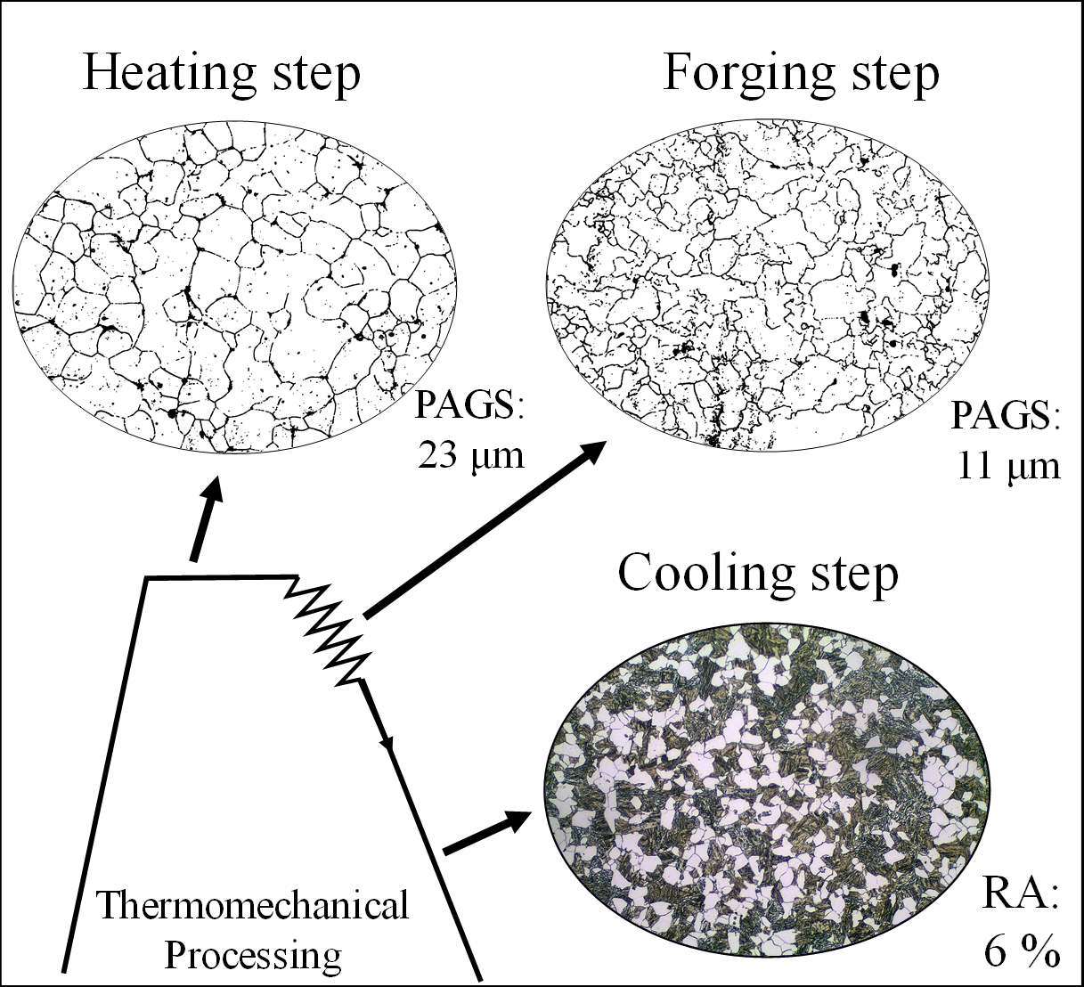
2.2. Hot Forging Experiments and Microstructure Evaluation

For the hot forging experiments, billets with 38-mm diameter and 54-mm height were machined from hot rolled steel bars. Forging was carried out in a 40-tonf (356-kN) hydraulic press equipped with a load cell and Linear Variable Differential Transformer (LVDT) to acquire force versus displacement curves during forging. Flat dies manufactured from hardened and tempered AISI H13 steel were used for the upsetting. Graphite water solution was applied to the surfaces of the dies as a forging lubricant. To simulate temperature losses of an ongoing industrial process, the dies were pre-heated by a resistance coil attached to the lower die (stationary); then, both dies were kept in contact for 1 h before forging to achieve temperatures around 250 and 180 °C for lower and upper die, respectively. The temperature losses between air and billet during transportation from the furnace to the press were quantified by type K thermocouples in the billet. The samples were submitted to a 60% height reduction. Figure 2a shows the thermomechanical routes. Three different routes were applied, with heating temperatures of 1000, 1100, and 1200 °C, always with a holding time of 10 min after the sample’s core had reached the heating temperature set in the furnace (minimum soaking time). For each route, one sample was water quenched for PAGS analysis, and another one was cooled in calm air to characterize the continuous cooled microstructure. Figure 2b shows a macrograph of a forged sample as an example, after a height reduction of 60%. Due to the friction and thermal losses to the dies, the top and bottom regions of the samples presented were excluded for PAGS and phase quantification; only the center areas (red rectangle) were used in the analysis.

2.3. Critical Strain

Based on the true flow stress curves from the hot forging experiments, the onset of dynamic recrystallization (DRX) can be determined by the double-differentiation technique proposed by Poliak and Jonas [20]. Equation (1) shows the basic equation for the strain hardening effect, where θ is the strain hardening rate, σ is the flow stress, and ϕ is the true strain.
θ = σ / ϕ
The Poliak and Jonas approach identifies the beginning of the DRX as an inflection point of the strain hardening rate. This inflection point is more easily seen as a minimum on the ( θ / σ ) vs. σ plot [21]. This minimum value corresponds to critical stress, which is equivalent to a critical strain, where strain hardening rates reach a minimum value indicating the recrystallization start acting point.

2.4. Metallurgical Characterization

Metallographic samples parallel to the compression direction from the forged billets and from the hot rolled bars (as-received microstructure) were prepared following standard procedures [22] and etched by immersion in a Nital 2% solution for 10 s. For PAGS characterization, a saturated aqueous picric acid solution was used. The etchant consists of wetting agent (42 mL), distilled water (58 mL), and picric acid (2.3 g). The samples were etched by swabbing for 5 min.
The circular intercept procedure was adopted for the PAGS quantification [23]. From 6 to 12 images were used to achieve a good statistical significance, and the evaluations were performed with the Omnimet 9.8 Software from Buehler, IL, USA [24]. The ferrite quantification was carried out with the ImageJ Software after the binarization of the images from optical microscopy (OM). Vickers microhardness was measured using an INSIZE ISH-TDV 1000 microhardness tester according to ASTM standard E384 [25]. For each forged sample, thirty measurements were performed with a load of 1 kgf for 10 s at different testing positions of the samples to obtain a mean hardness value. Further tests were carried out with a lower load of 0.1 kgf applied for 10 s to evaluate the hardness of each microconstituent of the microstructure. Three measurements were performed per microconstituent. For all hardness tests, a distance larger than the recommended indentations spacing was adopted to assure no interference between measurements.
The Retained Austenite (RA) fraction was quantified using X-Ray Diffraction (XRD) analysis. Before the analysis, all samples were electropolished to remove approximately 100 µm in order to eliminate the possible effects of mechanical preparation. The measurements were performed with a GE-Analytical X-ray MZ VI E Diffractometer with Cr-Kα radiation with a wavelength of 2.2897 Å. A 2θ range of 60–164° was adopted to obtain the {111}, {200}, and {220} austenite peaks and {110}, {200}, and {211} ferrite peaks, with a 0.05° step size. The retained austenite (RA) phase quantification was done with the Rietveld refinement software TOPAS version 4.2 (Bruker AXS, Karlsruhe, Germany) [26].

3. Results and Discussion

3.1. Grain Growth

Figure 3a shows the evolution of PAGS as a function of temperature and time. PAGS of the as-received material (indicated as the gray dashed line), was found to be 24 µm. At 1000 °C, a slight growth was observed at 40 min of holding time (≈4 µm) in comparison to the initial grain size. At 1100 °C, no growth was noticed at time t = 0 min and 10 min. A sharper growth was observed at 20 min, followed by a stabilization of the grain size at t = 40 min. At 1200 °C and t = 0 min, the grain showed an increase of ≈20 µm with the highest growth between 10 and 20 min and a stabilization of the grain size at 40 min, similar to 1100 °C. However, at 1200 °C, PAGS had a significant data dispersion (indicated by the error bars). This dispersion happened because larger grains than those of the matrix are present in the microstructure, as indicated in highlighted in red in Figure 3b.
This heterogeneity in the grain size indicates that abnormal grain growth took place at 1200 °C; however, this affect was not observed at lower temperatures. The abnormal grain growth may be associated with the dissolution of precipitates formed by microalloying elements such as Ti, N, and Al present in the steel [27]. Based on the chemical composition of the steel and solubility equations for precipitates in austenite [28], the temperature for total dissolution can be calculated for carbides such as TiC (907 °C) and nitrides such as TiN (1339 °C) and AlN (1004 °C). These precipitates inhibit the growth of the austenitic grains due to pinning effect [29]. The presence of impurities such as S also promotes the formation of sulfites such as MnS (1701 °C), which can act as a barrier to the grain growth as well [30]. However, as the temperature rises, these precipitates can be totally or partially dissolved in the austenite or even coalesce, as may be the case with MnS bands. Hence, the pressure exerted by the pin particles decreases, leading to excessive grain growth, resulting in a nonhomogeneous microstructure [11,31,32,33].

3.2. Effect of the Hot Deformation Temperature

3.2.1. Austenitic Grain Refinement

Figure 4 shows the morphology of the PAGS immediately after the hot deformation step. The deformation at 1000 and 1100 °C (Figure 4a,b, respectively) resulted in similar refinement, achieving PAGS approximately 50% smaller than the material in its initial state. The resulting PAGS of the forging at 1200 °C showed a similar size to the material in its initial state, indicating no refinement of the austenitic grain by forging at this temperature (Figure 4c).

3.2.2. Critical Strain

Figure 5a shows the flow stress curves from the hot forging experiments indicating the critical strain for the onset of DRX, while Figure 5b shows the ( θ / σ ) versus σ , where the minimum values correspond to the critical stress for the beginning of DRX.
Figure 5 shows that, as the forging temperature increases, the required strain necessary to initiate the DRX decreases. The hot forging at 1200 °C presented a smaller critical strain for the initiation of the DRX, and, as the forging temperature decreases to 1100 and 1000 °C, a higher degree of deformation was required to start the recrystallization. Although an increase in temperature decreased the critical strain for recrystallization (due to an increase of the internal energy), larger initial grain sizes had the opposite effect by decreasing grain boundary area, which are preferred nucleation sites [34].
A comparison between the flow stresses curves (Figure 5a) and PAGS (Figure 4) from the forging experiments show that an increase in the forging temperature reduces the flow stress and results in a larger PAGS. This is expected since PAGS during forging is associated to the strain rate and flow stress shape, which is controlled by the temperature [35]. Moreover, increasing the forging temperature means more time during cooling at temperatures where grain growth occurs, leading to a larger PAGS when the phase transformation starts. Even though recrystallization was observed at 1200 °C, the microstructure was subjected to longer periods at temperatures where grain growth occurred. As a result, the austenite grains grew sufficiently, reaching a similar size to PAGS of the as-received microstructure.

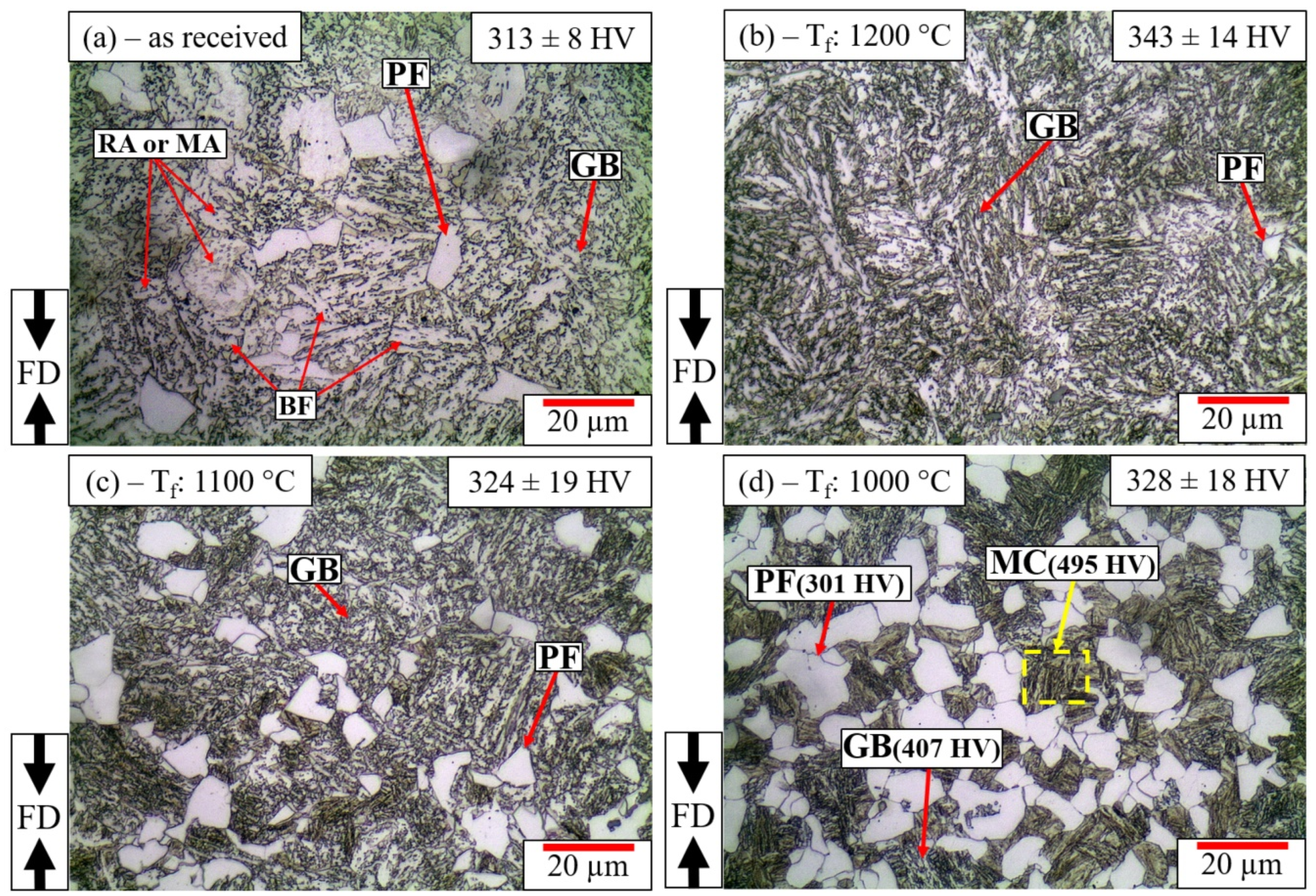
3.2.3. Continuously Cooled Microstructure

Figure 6 shows the microstructures and overall hardness of the samples forged and directly cooled by calm-air to room temperature in comparison with the as-received material. Figure 6a shows the as-received microstructure composed mainly of Granular Bainite (GB), which is characterized by Bainitic Ferrite (BF) (white regions) between the blocky RA and martensite/austenite (M/A) shown as the darker regions in the figure. The Polygonal Ferrite (PF) is revealed as a massive white block. The hot forging at 1200 °C (Figure 6b) resulted in a GB microstructure with a small portion of PF. As the forging temperature decreased to 1100 °C, as indicated in Figure 6c, the fraction of PF increased. Figure 6d shows the resulting microstructure after forging at 1000 °C composed by a high fraction of PF, small fractions of GB, and an additional microconstituent highlighted in yellow (MC). The microhardness tests results for the microconstituents are 301, 407, and 495 HV 0.1 for PF, GB, and MC, respectively. The latter presents a similar morphology to martensite [36]. Moreover, its hardness is approximately 90 HV 0.1 higher than the GB, indicating that this may indeed be martensite.
Deformation can significantly affect the PF formation [37]. The increase dislocation density caused by the plastic deformation leads to more unstable austenite. Usually, this instability is countered by recovery and recrystallization. The latter refines the austenite grain, increasing the total area of the austenitic grain boundaries. The boundaries are the preferred sites for the ferrite nucleation during the cooling [15,38,39]. Thus, a higher quantity of PF can be formed from a microstructure with smaller PAGS. Moreover, the increase of defects caused by the plastic deformation also elevates the temperature of austenite–ferrite transformation A3. Therefore, hot forging at the lowest temperature of 1000 °C not only increased the number of possible nucleation sites but also favored the beginning of the transformation is closer to the A3 temperature of the steel [37].
The polygonal ferrite formation during cooling can affect the bainite formation in two different ways. As reported by Quidort and Brechet [40], the formation of a small fraction of ferrite at grain boundaries (less than 10%) increases the number of nucleation sites. Since the grain boundaries are also the preferred site for bainite nucleation, the presence of ferrite may accelerate the bainitic reaction. However, Zhu et al. [33] reported that, as the ferrite nucleates and grows, the carbon and other alloys diffuse to the remaining austenite (partitioning process). However, due to the diffusion limitation during the cooling, this enrichment is not homogeneous, resulting in an austenite–ferrite interface with a higher concentration of these elements and regions distant from the interfaces with a chemical composition closer to the initial composition shown in Table 1. This chemical heterogeneity in the austenite would inhibit the bainitic transformation at the interfaces (higher carbon and alloy content), while facilitating the martensite reaction at the center regions of the remained austenite with lower carbon and alloy content. Lambert et al. [41] also found martensite at the center of austenitic grain, indicating a similar chemical variation in the austenite and, by Transmission Electron Microscope (TEM), identified dislocations in the interior of the austenite which could initiate the martensite formation. This indicates that the microconstituent highlighted in yellow in Figure 6d could indeed be martensite.
Figure 7 shows the polygonal ferrite obtained by OM quantification, and the RA fraction obtained by the XRD analysis of the forged samples. Forging at 1000 °C resulted in 30% of PF, 6% of RA, and a small parcel of GB. As temperature increased, the PF fraction decreased, and RA and GB increased. At 1200 °C, the PF reduced to almost zero, resulting in a GB microstructure with 10% of RA. RA in the microstructure is mainly related to the carbide suppression caused by Si in the steel, resulting in a carbide free bainitic microstructure with stable RA at room temperature due to the carbon partitioning [42]. This result indicates that RA stability is closely related to the GB presence in the microstructure. With the PF formation at lower forging temperatures, a higher RA stability should be expected, increasing the RA fraction. However, the lowest fraction of RA is found in the microstructure with higher quantities of PF. This low fraction is possibly related to martensite formation at the austenite regions with lower carbon and alloying elements content. With the increase of forging temperature, a higher fraction of GB is formed, favoring the formation of RA during bainitic transformation.
Based on the retained austenite lattice parameter obtained from the TOPAS Rietveld method, the average carbon content of the RA was calculated according to Dyson and Holmes’s equation [43]. Figure 7 shows that, at 1000 °C, RA reached 1.2 ma. % of carbon; as the forging temperature increased, the carbon concentration reduced to 1 ma. % and 0.8 ma. % at 1100 and 1200 °C, respectively. This result shows that, despite the lowest fraction of RA at 1000 °C, the resulting austenite is highly carbon enriched. According to Xiong et al. [44], this heterogeneous chemical composition favors the formation of a high carbon blocky RA at the austenite/ferrite interface. At the same time, the austenite regions with lower carbon would transform to martensite, as explained above. At higher forging temperature, since lower quantities of PF forms and no martensite appears, the RA is enriched only by the GB formation.

3.2.4. Summary of the Microstructure Characterization

In this study, the effect of austenitizing temperature and forging temperature on the microstructure of bainitic steel was investigated using stress–strain curves and microstructure analysis. Table 2 shows the main results of thermomechanical processed samples at different forging temperatures. The characterization shows that the forging temperature resulted in different PAGS and significantly affected the phases fraction and the RA carbon content in solution. This means that, by changing the forging temperature, a range of microstructures can be obtained without modifying the cooling parameters. At 1000 °C, the smallest PAGS and the highest fraction of PF were achieved with the presence of a third microconstituent with superior hardness. Moreover, the lowest fraction of RA and GB were obtained. Forging at 1100 °C resulted in similar PAGS refinement with a reduction in the PF fraction and an increase in RA and GB fractions. At 1200 °C, PAGS shows similar size with the material as received, and the microstructure obtained is almost entirely bainitic with small fractions of PF and higher quantities of RA.

4. Conclusions

  • Heat treating experiments with different austenitizing temperatures and holding times were carried out to evaluate the prior austenite grain size. The prior austenite grain size results show that an austenitizing temperature of 1200 °C promoted a significant grain growth and the presence of abnormal grain growth, however, abnormal grain growth was not identified at 1100 and 1000 °C.
  • The temperature also affected the prior austenite grain size after the hot forging, which affected the phase fractions in the final continuous cooling microstructure, especially the polygonal ferrite formation.
  • X-ray diffraction analysis showed that the fraction of retained austenite was reduced as the forging temperature decreased due to the formation of higher quantities of polygonal ferrite. Moreover, the carbon content increased in austenite due to the growth of polygonal ferrite during cooling.
  • Hot forging at 1000 °C promoted the formation of 30% of polygonal ferrite, resulting in a chemical heterogeneity of the remaining austenite, leading to martensite formation at the austenite regions with lower carbon and alloying elements.
  • The granular bainite formation and retained austenite fraction are favored in the coarser austenitic microstructure obtained at higher hot forging temperatures.

Author Contributions

Conceptualization, A.C.d.F.S.; methodology, A.C.d.F.S. and P.J.d.C.; validation, A.C.d.F.S. and P.J.d.C.; formal analysis, A.C.d.F.S. and J.E.; investigation, A.C.d.F.S., P.J.d.C., and W.L.B.; data curation, A.C.d.F.S.; writing—original draft preparation, A.C.d.F.S.; writing—review and editing, A.d.S.R., W.L.B., V.W.D., P.J.d.C., and J.E.; visualization, A.C.d.F.S.; and Funding acquisition, A.d.S.R. and J.E. All authors have read and agreed to the published version of the manuscript.

Funding

This research was funded in part by the Coordenação de Aperfeiçoamento de Pessoal de Nível Superior—Brasil (CAPES)—Finance Code 001 and n° 1844/2017, Conselho Nacional de Desenvolvimento Científico e Tecnológico (proc 167149/2017-2 and Pq-2018, proc 308773/2018-7) and the Deutsche Forschungsgemeinschaft_DFG (ZO 140/21-1).

Acknowledgments

The authors express their gratitude to the following laboratories: Metal Forming Laboratory (LdTM), Foundry Laboratory (LAFUN), and Institut für Werkstofforientierte Technologien (IWT) for the investigation support and the company Swiss Steel for the material donation. Antonio Carlos de Figueiredo Silveira, William Lemos Bevilaqua, Vinicius Waechter Dias and Pedro José de thank the Coordenação de Aperfeiçoamento de Pessoal de Nível Superior (Brazil) (CAPES) and Conselho Nacional de Desenvolvimento Científico e Tecnológico (Brazil) (CnPQ) for the master and doctorate scholarships.

Conflicts of Interest

The authors declare no conflict of interest.

References

  1. Sourmail, T.; Smanio, V.; Ziegler, C.; Heuer, V.; Kuntz, M.; Caballero, F.G.; Garcia-Mateo, C.; Cornide, J.; Elvira, R.; Leiro, A.; et al. Novel Nanostructured Bainitic Steel Grades to Answer the Need for High-Performance Steel Components; European Commission: Brussels, Belgium, 2013. [Google Scholar] [CrossRef]
  2. Caballero, F.G.; Garcia-Mateo, C.; Cornide, J.; Allain, S.; Puerta, J.; Crouvizer, M.; Mastrorillo, T.; Jantzen, L.; Vuorinen, E.; Lindgren, L.E.; et al. New Advanced Ultra High Strength Bainitic Steels: Ductility and Formability. Res. Fund Coal Steel Eur. Commision 2013, 1–124. [Google Scholar] [CrossRef]
  3. Cao, J.; Yan, J.; Zhang, J.; Yu, T. Effects of thermomechanical processing on microstructure and properties of bainitic work hardening steel. Mater. Sci. Eng. A 2015, 639, 192–197. [Google Scholar] [CrossRef]
  4. Liang, X.; Deardo, A.J. A study of the influence of thermomechanical controlled processing on the microstructure of bainite in high strength plate steel. Metall. Mater. Trans. A Phys. Metall. Mater. Sci. 2014, 45, 5173–5184. [Google Scholar] [CrossRef]
  5. Zhao, L.; Qian, L.; Liu, S.; Zhou, Q.; Meng, J.; Zheng, C.; Zhang, F. Producing superfine low-carbon bainitic structure through a new combined thermo-mechanical process. J. Alloys Compd. 2016, 685, 300–303. [Google Scholar] [CrossRef]
  6. Sourmail, T. Bainite and Superbainite in Long Products and Forged Applications. HTM J. Heat Treat. Mater. 2017, 72, 371–378. [Google Scholar] [CrossRef]
  7. Bleck, W.; Bambach, M.; Wirths, V.; Stieben, A. Microalloyed Engineering Steels with Improved Performance—An Overview. HTM J. Heat Treat. Mater. 2017, 72, 346–354. [Google Scholar] [CrossRef]
  8. Fang, H.S.; Chun, F.E.; Zheng, Y.K.; Yang, Z.G.; Bai, B.Z. Creation of Air-Cooled Mn Series Bainitic Steels. J. Iron Steel Res. Int. 2008, 15, 1–9. [Google Scholar] [CrossRef]
  9. Hasler, S.; Roelofs, H.; Lembke, M.; Caballero, F.G. New air cooled steels with outstanding impact toughness. In Proceedings of the 3nd International Conferente On Steels in Cars and Trucks, Salzburg, Austria, 5–9 June 2011; p. 9. [Google Scholar]
  10. ASM. Handbook. Volume 14: Forming and Forging; ASM International: Materials Park, OH, USA, 1993; Volume 14, ISBN 0-87170-007-7. [Google Scholar] [CrossRef]
  11. Fernández, J.; Illescas, S.; Guilemany, J.M. Effect of microalloying elements on the austenitic grain growth in a low carbon HSLA steel. Mater. Lett. 2007, 61, 2389–2392. [Google Scholar] [CrossRef]
  12. Yang, Z.; Zhang, F.; Zheng, C.; Zhang, M.; Lv, B.; Qu, L. Study on hot deformation behaviour and processing maps of low carbon bainitic steel. Mater. Des. 2015, 66, 258–266. [Google Scholar] [CrossRef]
  13. Rancel, L.; Gómez, M.; Medina, S.F. Influence of Microalloying Elements (Nb, V, Ti) on Yield Strength in Bainitic Steels. Steel Res. Int. 2008, 79, 947–953. [Google Scholar] [CrossRef]
  14. Zhao, H.; Wynne, B.P.; Palmiere, E.J. Effect of austenite grain size on the bainitic ferrite morphology and grain refinement of a pipeline steel after continuous cooling. Mater. Charact. 2017, 123, 128–136. [Google Scholar] [CrossRef]
  15. Li, X.; Xia, D.; Wang, X.; Wang, X.; Shang, C. Effect of austenite grain size and accelerated cooling start temperature on the transformation behaviors of multi-phase steel. Sci. China Technol. Sci. 2013, 56, 66–70. [Google Scholar] [CrossRef]
  16. Rancel, L.; Gómez, M.; Medina, S.F.; Gutierrez, I. Measurement of bainite packet size and its influence on cleavage fracture in a medium carbon bainitic steel. Mater. Sci. Eng. A 2011, 530, 21–27. [Google Scholar] [CrossRef]
  17. Capdevila, C.; Caballero, F.G. Carlos García de Andrés Austenite Grain Size Effects on Isothermal Allotriomorphic Ferrite Formation in 0.37C-1.45Mn-0.11V Microalloyed Steel. Mater. Trans. 2003, 44, 1087–1095. [Google Scholar] [CrossRef] [Green Version]
  18. Ferry, M.; Thompson, M.; Manohar, P.A. Decomposition of coarse grained austenite during accelerated cooling of C-Mn steels. ISIJ Int. 2002, 42, 86–93. [Google Scholar] [CrossRef] [Green Version]
  19. Celada-Casero, C.; Sietsma, J.; Santofimia, M.J. The role of the austenite grain size in the martensitic transformation in low carbon steels. Mater. Des. 2019, 167. [Google Scholar] [CrossRef]
  20. Poliak, E.I.; Jonas, J.J. A one-parameter approach to determining the critical conditions for the initiation of dynamic recrystallization. Acta Mater. 1996, 44, 127–136. [Google Scholar] [CrossRef]
  21. McQueen, H.J.; Yue, S.; Ryan, N.D.; Fry, E. Hot working characteristics of steels in austenitic state. J. Mater. Process. Technol. 1995, 53, 293–310. [Google Scholar] [CrossRef]
  22. ASM International (Ed.) Volume 9: Metallography and Microstructure, 9th ed.; ASM International: Materials Park, OH, USA, 2004; Volume 9, ISBN 0871707063. [Google Scholar]
  23. ASTM Standard. E112-12:Standard Test Methods for Determining Average Grain Size; ASTM International: Materials Park, OH, USA, 2012. [Google Scholar] [CrossRef]
  24. Voort, G. Vander Introduction to quantitative metallography. Buehler TechNotes 2015, 1, 5. [Google Scholar]
  25. ASTM International. E384 Standard Test Method for Microindentation Hardness of Materials; ASTM International: Materials Park, OH, USA, 2017; pp. 1–40. [Google Scholar] [CrossRef]
  26. Dinnebier, R.E.; Leineweber, A.; Evans, J.S.O. Rietveld Refinement—Practical Powder Diffraction Pattern Analysis Using TOPAS; De Gruyter, Ed.; De Gruyter: Berlin, Germany; Boston, MA, USA, 2018; ISBN 9783110456219. [Google Scholar] [CrossRef]
  27. Razzak, M.A.; Perez, M.; Sourmail, T.; Cazottes, S.; Frotey, M. Preventing Abnormal Grain Growth of Austenite in Low Alloy Steels. ISIJ Int. 2014, 54, 1927–1934. [Google Scholar] [CrossRef] [Green Version]
  28. Totten, G.E.; Xie, L.; Funatani, K. Handbook of Mechanical Alloy Design; CRC Press: New York, NY, USA, 2003; ISBN 978-0-8247-4308-6. [Google Scholar] [CrossRef]
  29. Zener, C. Theory of Growth of Spherical Precipitates from Solid Solution. J. Appl. Phys. 1949, 20, 950. [Google Scholar] [CrossRef]
  30. Guo, L.; Roelofs, H.; Lembke, M.I.; Bhadeshia, H.K.D.H. Effect of manganese sulphide particle shape on the pinning of grain boundary. Mater. Sci. Technol. 2017, 33, 1013–1018. [Google Scholar] [CrossRef] [Green Version]
  31. Totten, G.E. Steel Heat Treatment; Taylor & Francis Group: Abingdon, UK, 2006; pp. 1–820. ISBN 978-0-8493-8455-4. [Google Scholar]
  32. Li, M.; Li, J.; Qiu, D.; Zheng, Q.; Wang, G.; Zhang, M.X. Crystallographic study of grain refinement in low and medium carbon steels. Philos. Mag. 2016, 96, 1556–1578. [Google Scholar] [CrossRef]
  33. Zhu, K.; Chen, H.; Masse, J.P.; Bouaziz, O.; Gachet, G. The effect of prior ferrite formation on bainite and martensite transformation kinetics in advanced high-strength steels. Acta Mater. 2013, 61, 6025–6036. [Google Scholar] [CrossRef]
  34. Humphreys, J.; Rohrer, G.S.; Rollett, A. Recrystallization and Related Annealing Phenomena. In Recrystallization and Related Annealing Phenomena, 2nd ed.; Elsevier: Amsterdam, The Netherlands, 2017; pp. 1–734. ISBN 978-0-08-098235-9. [Google Scholar]
  35. Derby, B. The dependence of grain size on stress during dynamic recrystallisation. Acta Metall. Mater. 1991, 39, 955–962. [Google Scholar] [CrossRef]
  36. Krauss, G. Steels: Processing, Structure, and Performance, 2nd ed.; ASM, I.H.C., Ed.; ASM International: Materials Park, OH, USA, 2005. [Google Scholar]
  37. Sietsma, J. 14—Nucleation and growth during the austenite-to-ferrite phase transformation in steels after plastic deformation. In Phase Transformations in Steels; Woodhead Publishing Limited: Sawstone, Cambridge, UK, 2012; Volume 1, pp. 505–526. ISBN 9781845699703. [Google Scholar] [CrossRef]
  38. Aranda, M.M.; Kim, B.; Rementeria, R.; Capdevila, C.; De Andrés, C.G. Effect of prior austenite grain size on pearlite transformation in A hypoeuctectoid Fe-C-Mn steel. Metall. Mater. Trans. A Phys. Metall. Mater. Sci. 2014, 45, 1778–1786. [Google Scholar] [CrossRef] [Green Version]
  39. Lan, H.F.; Du, L.X.; Liu, X.H. Microstructure and mechanical properties of a low carbon bainitic steel. Steel Res. Int. 2013, 84, 352–361. [Google Scholar] [CrossRef]
  40. Quidort, D.; Brechet, Y.J.M. Isothermal growth kinetics of bainite in 0.5% C steels. Acta Mater. 2001, 49, 4161–4170. [Google Scholar] [CrossRef]
  41. Lambert, A.; Drillet, J.; Gourgues, A.F.; Sturel, T.; Pineau, A. Microstructure of martensite-austenite constituents in heat affected zones of high strength low alloy steel welds in relation to toughness properties. Sci. Technol. Weld. Join. 2000, 5, 168–173. [Google Scholar] [CrossRef]
  42. Caballero, F.G. Carbide-free bainite in steels. In Phase Transformations in Steels; Elsevier: Amsterdam, The Netherlands, 2012; Volume 1, pp. 436–467. ISBN 9781845699703. [Google Scholar] [CrossRef]
  43. Dyson, D.J. Holmes B effect of alloying additions on the lattice parameter of austenite. J. Iron Steel Inst. 1970, 208, 469–474. [Google Scholar]
  44. Xiong, X.C.; Chen, B.; Huang, M.X.; Wang, J.F.; Wang, L. The effect of morphology on the stability of retained austenite in a quenched and partitioned steel. Scr. Mater. 2013, 68, 321–324. [Google Scholar] [CrossRef]
Figure 1. Optical microscopy of the DIN 18MnCrSiMo6-4 as-received microstructure.
Metals 10 00601 g001
Figure 2. (a) Thermomechanical routes. tsmin, minimum soaking time. (b) Half-section macrograph of the forged sample. The red rectangle indicates the analyzed area. The yellow circle labeled 1 indicates the position from where the micrographs shown in this work were taken.
Metals 10 00601 g002
Figure 3. (a) Effect of temperature and holding time on austenitic grain; and (b) PAGS microstructure after austenitizing at 1200 °C with 0 min of holding time, indicating the presence of abnormal grain. Highlighted grain has a mean size of 200 µm and the matrix 45 µm.
Metals 10 00601 g003
Figure 4. Optical microscopy of the PAGS after hot deformation with 60% of reduction at (a) 1000 °C; (b) 1100 °C; and (c) 1000 °C Tf, forging temperature; FD, forging direction.
Metals 10 00601 g004
Figure 5. (a) Flow stress curves of the hot forging experiments with the critical strain for the onset of the DRX; and (b) ( θ / σ ) versus σ curve, where the minimum value corresponds to the critical stress.
Metals 10 00601 g005
Figure 6. Optical microscopy of (a) as-received condition and forged samples cooled in calm air: (b) forged at 1200 °C; (c) forged at 1100 °C; and (d) forged at 1000 °C. PF, polygonal ferrite; GB, granular bainite; MC, third microconstituent; RA, retained austenite; MA, martensite/austenite; BF, bainitic Ferrite; FD, forging direction.
Metals 10 00601 g006
Figure 7. The effect of the forging temperature on the PF and RA fractions and carbon content of the austenite.
Metals 10 00601 g007
Table 1. Chemical composition (in ma. %).
CSiMnSNiCrCuMoAlTiNFe
0.181.191.420.0150.0631.170.100.270.0050.0040.01Balance
Table 2. Summary of the microstructure characterization.
Forging TemperaturePAGS (μm)MicrostructurePF Fraction (vol. %)RA (vol. %)CRA Content (ma. %)Overall Hardness (HV 1)
As received24 ± 3.2GB + PF3.5 ± 1.810.50.8313 ± 8
1000 °C11 ± 1.7PF + MC + GB30.0 ± 5.86.31.2328 ± 18
1100 °C13 ± 3.0GB + PF20.0 ± 5.48.81.0324 ± 19
1200 °C28 ± 5.3GB + PF1.3 ± 0.810.10.8343 ± 14

