Abstract
In practice, structures of pallet racks are characterized by very wide options of beam-to-column connections. The up to date part of the standard Eurocode 3 considers details for the design of connections. However, experimental determination of the joint properties in steel pallet racks is the most reliable process, since it takes into account an inability to develop a general analytical model for the design of these connections. In this paper, a test procedure for the behavior of beam-to-column connections is presented and the results are analyzed according to the procedure defined in the relevant design codes. With aim to avoid expensive experiments to determine structural properties of different types of connections, a polynomial model and a corresponding numerical model were developed to be used for simulating the experiment. After verification, the developed analytical and numerical model can be applied for investigation of various combinations of beam-to-column connections.
1. Introduction
Racking systems play a key role in satisfying today’s manufacturing and distribution needs that are determined by competitive markets. When choosing storage equipment, an engineer is faced with a wide variety of options. Racking systems, ranging from selective/adjustable racks, double-deep, drive-in or drive-through configurations, to live pallet storage, push-back and mobile storage systems, are all conventional pallet racking configurations. All these different types of racks vary slightly in their structure and functioning. They are self-sustaining thin-walled steel constructions, with the ability to carry significant vertical and lateral loads. Racking systems are designed as easy-to-install structures and this means that connections must be easily detachable in order to allow the users to change the layout according to their needs. Thus, bolted and welded connections do not qualify for these purposes. The design and development of connections between parts of the spacious pallet racking system are very important due to carrying the capacity and profitability of a steel structure. Cold-formed, boltless, semi-rigid connections between the beams and columns of a frame pallet structure offer cost savings from materials and from the costs of manufacturing and assembly, which are the main reason for their wide application. Nevertheless, pallet rack structures are prone to structural failure due to lateral loads e.g., seismic loads due to semi-rigid connections between the beams and columns. For this reason, special European standards and regulations give guidelines for structural design requirements to all types of adjustable pallet racking systems, especially for the self-sustaining warehouses, fabricated from steel members subject to seismic actions. The modern technical practice treats connections according to the European Eurocode 3 standard [1]. The study on joint rigidity dates back to the beginning of the 1990s, including both the experimental study and the analytical approach. However, the studies on joints in cold-formed steel structures, particularly those of pallet rack systems, are only a few decades old.
A simple design approach which ensures the stability of pallet rack structures and includes the influence of the form of the moment-rotation characteristics on the type of stability of the system was described by Lewis in 1991 [2].
In order to determine the parameters governing an efficient beam-end-connector design, Markazi et al. [3] performed tests on four different types of beam-end-connectors. Research presented in reference [4] implies that the required ductility does not depend on the stiffness of the connector. A comparison between results of an elastic 3D linear analysis of the connector and corresponding experimental results is presented and discussed in reference [5].
The research presented by Bernuzzi et al. [6] in 2001 points out the impracticality of analytical tools in the prediction of the stiffness and strength of connectors due to wide variations in the beam-end connectors and the fact that major international codes for rack design demand the conducting of experiments in order to determine the properties of connectors.
Using the cantilever and double cantilever test set-ups, Bajoria and Talikoti [7] conducted experiments to determine the flexibility of the beam-to-column connectors of conventional pallet racking systems. For the verification of results, a full-scale frame test was conducted. The double cantilever set-up was found to be superior to the conventional single cantilever test because the shear-to-moment ratio in an actual frame is better presented by this test. In addition, both tests together with the full-scale test were subjected to non-linear finite element analyses.
Prabha et al. [8] proposed two analytical models for the calculation of the stiffness of cold formed boltless semi-rigid pallet rack connections: the polynomial model based on the Frye-Morris method and the power model. It was established that the polynomial model predicts the initial stiffness of the tested connections reasonably well and that it is useful in linear design space, while the power model can predict the ultimate capacity of the connection.
The results of the experimental tests conducted on double-sided semi-rigid beam-to-column joints as predominant joints in typical pallet racking systems were analyzed by Krolin 2014. A comparison between the experimentally obtained stiffness and the bending moment of the double-sided and the single-sided joints was presented in reference [9].
Large displacements, geometrical properties and material nonlinearities were taken into account in a 3D non-linear finite element model developed in Shah et al. [10] in 2016. The model was verified by comparing the numerical data with experimental data; good agreement between the two sets of results was obtained.
In order to predict the initial rotational stiffness of the beam-to-column connections used in cold-formed steel racks, Zhao et al. [11] developed a corresponding mechanical model in 2017. The model was verified by experiments and the obtained results showed good agreement between the initial rotational stiffness given by the model and that recorded in the experimental results. The main factors influencing the observed initial rotational stiffness of the connections that were included in the model were also discussed in the paper.
In 2018, Gausella et al. [12] presented the results of monotonic and cyclic tests carried out on four different types of industrial rack joints. The experimental results from the cyclic tests enable the moment-rotation curves of joints to be accurately defined, confirming that the industrial rack joints are significantly different from traditional joints used in steel framed buildings due to the pinching in hysteresis loops. The curves obtained in the cyclic tests can also be used for reliable modeling of joints in the analysis of seismic behavior of steel pallet racks.
The behavior of the beam-to-column connections and the column bases has a major influence on the stability of rack structures [2,3,4,5,6,7,8,9,10,11,12]. Complex design details such as different mechanical devices used in beam-to-column connections (tabs and hooks without bolts and welds) do not allow the flexural behavior of the beam-to-column connections of steel storage racks to be easily predicted.
The properties of the beam-to-column connections can be determined only through experiments because it is currently impossible to develop a general analytical model. In this paper, with aim to define moment-rotation curve (M-Φ curve) a test procedure for the behavior of beam-to-column connections is presented and the results are analyzed according to the procedure (cantilever and/or portal test method) defined in the current design codes for steel pallet racks, FEM (European Materials Handling Federation) [13] and European standard EN 15512 [14]. Since the experiments are too expensive, in order to reduce the costs of determination of joint properties, this paper presents a polynomial model as well as numerical model developed for the simulation of the experiment. After the verification of the models by comparing the simulation results with the available experimental results, the proposed models can be applied to various combinations of beam-to-column connections. The model makes it possible to determine characteristics of connections. The determined structural properties can be used for the comprehensive study of the racking structure and for the analysis of each element by following the proceedings from the code [13] and standard [14]. European Standard EN 16681 [15] deals with all the relevant and specific seismic design issues for racking systems, based on the criteria defined in EN 1998-1, Eurocode 8 [16]. While the basic technical description of an earthquake is the same for all structures, the general principles and technical requirements applicable for conventional steel structures have to be adapted for racking systems, in order to take the peculiarities of racking to achieve the requested safety level into account [15].
2. Configuration of a Pallet Racking
A typical selective pallet rack configuration is shown in Figure 1. The side frames and horizontal beams, usually made of thin-walled cold-formed profiles, form a spatial frame structure of the pallet racking system. The horizontal and vertical bracing system of frames provides the rack stability in the cross-aisle direction. The beam-to-column connectors as a special part are welded to the beams or otherwise formed as an integral part of the beam. They have special devices like tabs, stud or hooks engaged in the perforations of the column. In this way, through the stiffness of the beam-to column connection, the stability of the rack in the direction of the corridor is ensured.
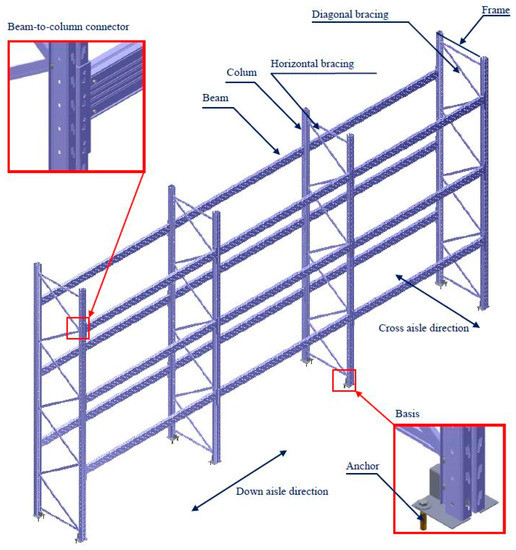
Figure 1.
Parts of the racking system.
In general, starting from the traditional assumption of the ideal connections among the elements in the joint, connections are classified as rigid or elastic. Nevertheless, the modern practice and experiments have confirmed behavior of some joints between ideal characteristics. Thus, a new division of the joints arose on:
- simple or elastic joints,
- semi-rigid joints and.
- continuous or rigid joints.
The new semi-rigid joint between the main racking elements provides completely specific behavior of spatial racking structure. Such behavior of joint in thin walled structures of rack is caused by deformation of the special devices on a beam-end connector, destruction of the upright perforation and distortion of the column walls. In practice, there are different types and designs for these connections, which are characteristic of different producers of racks [3].
3. Analytical Approach and Experimental Study on Beam-to-Column Connections
The diagram shown in Figure 2 defines correlation between the bending moment at the connecting point, Mj,Ed, and the relative rotation of the joint, ΦEd. This M-Φ curve (M-Φ characteristic) can be reliably determined in several ways: through an experiment, by using semi-empirical expressions developed for different connections or by using numerical methods or the recommendations from FEM codes and Eurocodes. Sometimes the real M-Φ curve includes some initial deviations due to the various effects such as insufficient alignment of the elements in the assembly or mistakes in production and installation.
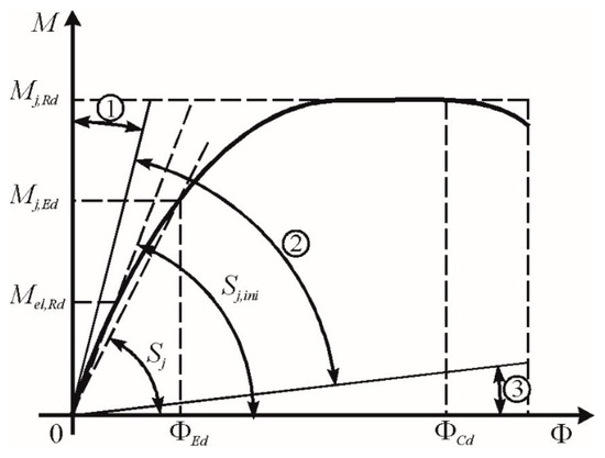
Figure 2.
Moment-rotation characteristics.
The outcome can be the significant initial rotation and this mast be taken into account when deriving the M-Φ curve.
Three zones with their boundaries (1, 2 and 3, respectively) corresponding to the rigid, semi-rigid or simple joints with their structural properties that can be determined by using the M-Φ curve are shown in Figure 2:
- bending strength, Mj,Rd,
- rotational stiffness, Sj, and
- rotational capacity, ΦCd.
3.1. Cantilever Test
The purpose of the test is to determine the stiffness and the bending strength of the beam-end connector [13,14]. The behavior of the beam-to-column connection is influenced by both members in the joint with many of their characteristics. Some of the factors, which must be taken into account during the analysis of joint behavior, are:
- the column profile,
- the thickness of the column wall,
- the beam profile,
- the thickness of the beam walls,
- the position of the connector on the beam,
- the way of connection between the connector and the beam,
- the connector type and
- the characteristics of the materials for all elements in the connection.
The combinations of the factors of the beam-to-column connection mentioned above that occur within the pallet racking system should be considered separately.
According to the standard procedure defined in [13] and [14] for each beam-end connector column joint, a minimum of three identic tests should be done in order to statistically interpret obtained results.
3.1.1. Experiment Set-up
Figure 3 shows cantilever bending test arrangement. Within the very rigid testing frame as shown in the Figure 3, a short part of the racking column is fitted whose length should satisfy the following condition:
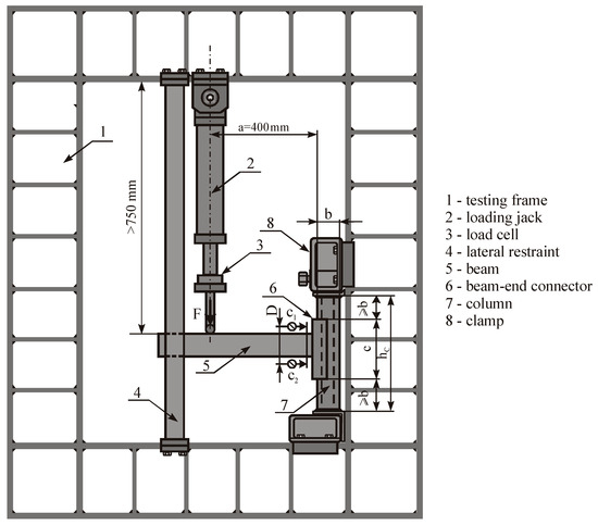
Figure 3.
Cantilever test set-up.
During the experiment, the column should not come in the contact with the testing frame outside this distance. Connection between short piece of the beam and stiff column is obtained over a beam-end connector. The beam is secured from disassembling by means of a beam locks during the test.
A special part of the experiment settings is lateral guides, which prevent lateral movement and twisting of the beam end. However, these guides provide the beam end to move freely in the direction of the applied force.
The force is applied at a distance of 400 mm far from the perforated face of the column by a loading jack that is at least 750 mm long between the support at the testing frame and beam level according to the test set up. The rotation shall be determined by either of the following:
- two gauges C1 and C2 as shown in Figure 3 bearing onto a plate fixed to the beam near to the connector, but far from it in order to allow for connector distortion, or
- by an inclinometer connected to the beam close to the connector.
A complete procedure for cantilever bending test is defined in code [13] and standard [14].
Table 1 shows four combinations of tested samples with different size of column and beam wall thickness. Materials with their standard properties used for elements of the connection are S350 GD Z 200 UNI EN 10326 for the column and S320 GD Z 200 UNI EN 10326 for the beam.

Table 1.
Joint combinations of columns and beams.
Dimensions of all parts in the connection and their position necessary for the experiment performing are shown in Figure 4. Table 2 shows values of all dimensions shown in Figure 4 for the five samples of three tested joints made by the same producer.
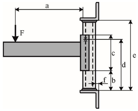
Figure 4.
Arrangement of the parts of the sample.
Table 2.
Dimensions of the elements in connection.
The disposition of measuring devices is shown in Figure 5. In Table 3, dimensions of the position of all devices for measuring displacement are given. Bending tests were performed on five samples of each joint as shown in Table 2 and Table 3. Each sample consists of the short part of the beam with beam-end connector connected to the short part of the racking column and secured from the disassembling by a beam lock. The samples of each joint marked from 5 to 8 are subjected to the force which generates positive bending moment under normal operating conditions, while the fifth sample marked as 9 is loaded in such a way that the applied force generates a negative bending moment which endeavors to separate the connection.
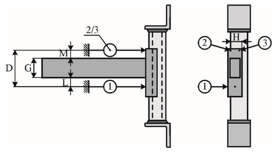
Figure 5.
Disposition of the measuring equipment.
Table 3.
Dimensions of the position of measuring equipment.
3.1.2. Experiment Procedure
Within the performed tests, the applied force acting in the downward direction parallel to the beam-end connector causes shear. If tests in the upward direction show the results for stiffness and strength, which are less than 50% of the values measured in these tests, then the actual figures will be measured to be used in the design. The design of the connectors should use the mean value for the stiffness and strength obtained from the values for the right and left connectors.
The load, F, must be slowly increased until the moment at the connector reaches a value equal to 10% of the failure moment in order to mount the components. After assembling of the parts, load should be removed and displacement transducers reset. Then, the gradual increase of the load F should be applied until the maximum is reached and the connection breaks.
For each test, the moment, M, and the rotation, Φ, should be plotted using the following relations [13,14,17]:
and
where:
- a—the length at which the force F acts,
- D—distance between the displacement transducers on the opposite sides of the beam,
- δ1, δ2—displacement measured by gauges C1 and C2.
Finally, the connection rotation, Φ, is determined according to the expression:
where:
- δ3 is the displacement measured by gauge C3,
Cantilever bending tests on beam-end connectors up to their collapse under normal operating conditions (bending moment is conventionally defined positive) were performed on the racking elements described previously. Initial loading-unloading cycles for the assembly and fitting of the connected parts were provided, up to the maximum load level of F0, after which the load was increased incrementally until it reached the value of the failure load, Fti. Table 4 shows the maximum measured values of the achieved force, F, for each sample, with corresponding failure moments, Mti, calculated according to formula (2). Duration of each test, t, is also given in Table 4 for each sample.
Table 4.
Values of the obtained force and moment.
3.1.3. Test Results
The maximum observed moment seen in Figure 6 is the failure moment, Mti. The mean value, Mm, of the individual test results is:
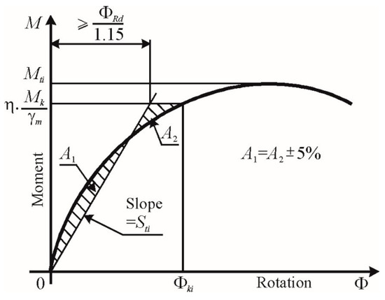
Figure 6.
Derivation of moment-rotation relationship.
For each tested joint, the characteristic failure moment, Mk, can be determined according to procedure defined in [13] for the derivation of characteristics values as following:
in which:
ks is the coefficient given in [13], which depends on the number of tests (for n = 4, ks = 2.68),
s is the standard deviation of the adjusted test results according to the following expression [13]:
The design moment, MRd, for the connection is as follows:
in which:
γM is the partial safety factor for connections, [1,13],
η is variable moment reduction factor selected by the designer ≤ 1.
It is permissible to choose any value of the design moment less than or equal to the allowable maximum in order to optimize the possibly conflicting requirements for stiffness and strength. Thus, by reducing the design strength, it is possible to achieve a greater design stiffness.
The rotational stiffness of the connector, Sti, is the slope of the line going through the origin and forming the equal areas between the straight line and the experimental curve below the design moment, MRd, (Figure 6), under condition [15]:
The design value of the connector stiffness, Sd, should be taken as the average value, Sm, as shown in Table 5, where:
Table 5.
Obtained experimental results.
3.2. Frye-Morris Polynomial Model
The Frye-Morris method [8] proposes a non-dimensional polynomial model for determining the moment-rotation characteristic of a single connection; the model is generated by replacing the numerical values of its individual parameters in a standardized connection. The parameters used to determine the equation can be: the thickness of the wall of the column, tu, the beam height, db and the thickness of the wall of the beam profile, tb. The standardized link is then given by the equation:
where:
- Φr—relative rotation in rad,
- M—moment of rotation in Nmm,
- K—coefficient that scales the ordinate of curves,
- C1, C2C3—constants for curve fitting.
The coefficient K which scales the ordinates of the curves taking into account the numerical value of the individual connection parameters is calculated according to:
where:
- qj—numerical value of j parameter,
- aj—exponent that shows the effect of the numerical value of the j parameter on the moment-rotation relation,
- m—number of parameters j.
The determination of the exponent aj in Equation (12) is performed on the basis of the pair of experimentally obtained moment-rotation curves for two identical joints, but in which the parameter qj is not included.
The relationship between the moments M1 and M2 for connections 1 and 2 at rotation Φ is assumed in the form:
where qj1 and qj2 are the values of the parameters qj for connections 1 and 2, respectively.
From relation (13), the coefficient aj can be expressed according to:
Expression (14) is used to calculate the values of aj corresponding to different rotations for each combination of experimental curves. When the mean value is calculated for all “m” exponents aj, they are applied to a standardized moment-rotation diagram. Finally, the curve fitting is done to generate a standardized moment-rotation connection.
The mean value of a1 for variable column thickness is −0.126, the mean value of a2 for variable heights of the beam is −2.981 and the mean value of a3 for the variable thickness of the beam is −0.121.
Therefore, the standardized coefficient K is expressed as:
Constants for curve fitting obtained for all connectors are shown in Table 6. They are calculated using a procedure developed in Microsoft Excel [17].
Table 6.
Constants for curve fitting.
The mean values of the coefficients are:
C1 = 43.693; C2 = 0.0393; C3 = 0.000435.
The Frye-Morris equation for the observed structure is:
4. Numerical Analysis of Beam-to-Column Connection
4.1. Finite Element Model of Cantilever Test
As a state-of-the-art method in the field of structural analysis, the Finite Element Method is commonly addressed to provide accurate and reliable predictions of structural deformation and stress states. Recent developments [18] enable high computational efficiency of finite element models even if nonlinear effects are involved. Finite element models for the cantilever test were generated in Femap with the NX Nastran software version 2019 sold by software company Siemens Digital Industries Software from Plano, TX, USA, based on the data given in the tables in chapter 3.1.1 provided by the producer of the equipment. The numerical analysis was conducted using the elasto-plastic material model with kinematic reinforcement made in the LS-Dyna software version R.9.0.1. developed by Livermore Software Technology Corporation (LSTC) from Livermore, CA, USA. The elements of the tested samples, shown in Figure 3 are modeled with finite elements as following:
- Column with 41,356 3D 8-nodal finite elements, Figure 7a.
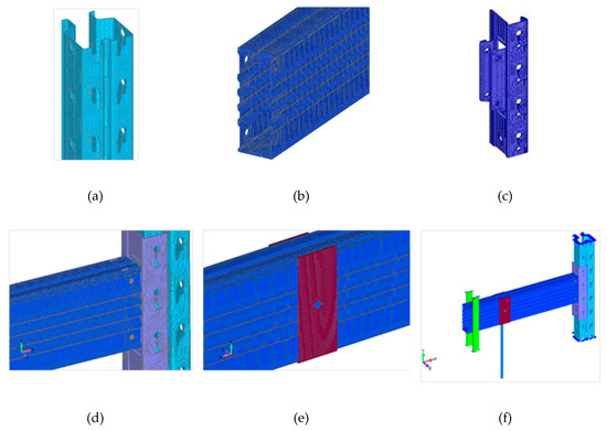 Figure 7. Finite element model of elements of cantilever test: (a) Column; (b) Beam; (c) Beam-end connector; (d) Screw; (e) Loading transfer plate; (f) Boundary conditions and the applied load.
 - Beam with 150,540 3D 8-nodal finite elements, Figure 7b.
- Beam-end connector with 63,777 3D 8-nodal finite elements, Figure 7c.
- Screws for joint beam-end connector and beam with 3395 3D 8-nodal finite elements, Figure 7d.
- Load transfer plate with 4136 shell elements, Figure 7e.
- 1D finite elements, i.e., rods were used for load modeling, Figure 7f.
- Surface-to-surface contact elements were used for the connected parts in samples: the column-beam end connector, beam end connector-beam and beam parts for blocking the lateral movement.
As shown in Figure 7f, the corresponding movement acts according to the diagram shown in Figure 8 along the direction of the rod. Actually, the value of the movement at the end of the rod on which the load acts is calculated using the experimental data based on dependence between the angle of rotation and the corresponding force value, i.e., the bending moment.
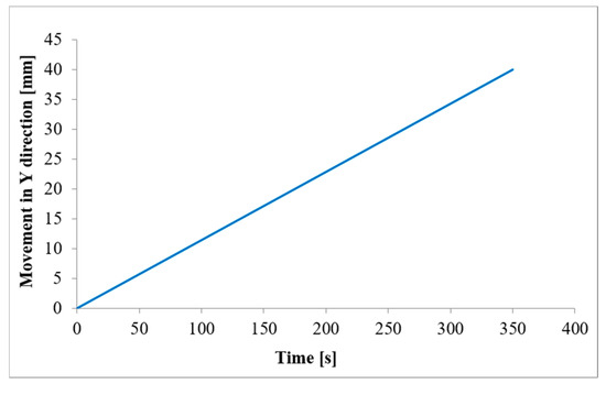
Figure 8.
Diagram of the displacement.
Figure 9 shows the experimentally obtained M-Φ curves for the four tested samples of the S80ML-R140L joint, the curve generated by using the analytical polynomial model of the Frye-Morris method, and the curve generated using a finite element model of the tested joint.
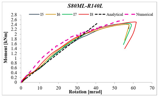
Figure 9.
Moment-rotation curves for the S80ML-R140L joint.
Very good agreement between the experimental results and the proposed polynomial model of the initial part of the moment-rotation capacity curve can be observed in Figure 9. The Frye-Morris method-based analytical polynomial model contains the standardization coefficient K, which involves three dimension parameters: column wall thickness, beam profile height and beam profile wall thickness. This constant is evaluated using the experimental results. The numerical analysis made by the LS-Dyna software showed that the finite element model developed using the test results was the best fit for experimental behavior. Figure 10 shows the deformation of one of the tested samples and displacement fields obtained by the numerical model, which shows good agreement. That is why the validated finite element model can be used in further parametric studies.
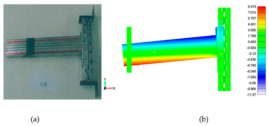
Figure 10.
Comparison of the results of the tested joints S80ML-R140L: (a) Deformation of the tested sample (b) Displacement field in the x direction obtained by the numerical model.
Figure 11 shows the M-Φ curves for the S80M-R140M joint obtained by the numerical model and the analytical application of expression (14). Using the described methodology for determination of the rotational stiffness of the connection according to references [13,15], defined in chapter 3.1.3, a value of 74.65 kNm/rad was obtained for the observed joint, as shown in Figure 11. The use of the numerical model only has its limitations because the applied maximum moment resistance is the mean value in determination of the rotational stiffness [15]. However, despite this limitation, developed finite elements model can be applied to determine the structural properties of the beam-to-column connection.
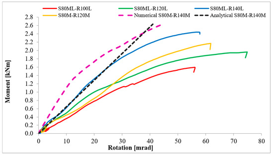
Figure 11.
Comparative average moment-rotation curves for the tested samples and numerical model.
The numerical model provides a detailed further investigation of each constituting part as well as of the structure as a whole. In addition, the validated finite element model can be used for a parametric analysis and identification of the effects of various parameters on the overall performance of the observed beam-to-column connection. Further parametric studies should analyze the influence of the number of tabs or hooks, the column thickness and the connector depth. The design of the beam-to-column connector and the efficiency of the accompanying members (beam, column) determine the moment-rotation characteristics of the joint.
4.2. Influence of the Column and Beam Wall Thickness on the Behaviour of the Connection
Comparing the average moment-rotation characteristics for tested samples (shown as green and orange curves in Figure 11) with the simultaneous change of the thickness of the wall of the column profile from 1.5 mm to 2.0 mm and the thickness of the wall of the beam profile from 1.00 mm to the 1.25 mm, with the same other parameters of the joints (height of the beam profile and beam-end connector), the bending strength is increased by 10%. The rotational stiffness remains almost unchanged. Further analysis of the behavior of the joint S80M-R140M numerically obtained, given as pink curve in Figure 11, with the experimentally curve of the joint S80ML-R140L, shows increasing of the bending strength by 13%, while rotational stiffness is increased by 15% after taking in consideration the limitations of the numerical model. From this analysis, it follows that the wall thickness of the column and beam profile has a dominant influence on the bending strength of the connection.
4.3. Influence of the Height of the Beam Profile and Beam-End Connector on the Behaviour of the Connection
Observing the joints with the same column wall thickness of 1.5 mm and the same height of the beam-end connector, with three “teeth” of 215 mm height, after changing only the height of the beam profile with the wall thickness of 1.00 mm from 100 mm up to 120 mm as shown in Figure 11 on red and green curves, the bending strength and rotational stiffness increases proportionally by 20%. However, by changing the height of the beam profile from 100 mm to 140 mm, the bending strength increases proportionally by 40%, while the rotational stiffness increases by 70% as shown in Figure 11 with red and blue curves and the data given in Table 5. The beam-end connector with three teeth in height had to be changed with a four-tooth connector from 215 mm to 290 mm. The conclusion is that dominant influence on the rotational stiffness has a beam-end connector with its parameters.
5. Conclusions
Better cognition of behavior of the beam-to-column connection based on the M-Φ characteristics is of great importance for comprehensive analysis of the joint in the structure and its influence on the whole spacious construction of racking system. Design codes like the FEM [13] or EN 15512 standard codes [14] demand experimental testing for which they supply the testing protocols with marginal differences for predicting the moment-rotation M-Φ behavior of any pallet rack beam-to-column connection. However, the prescribed experimental testing is expensive, so a possible solution may be found in the development of a particular uniform M-Φ relationship for each type of connection in terms of parameters by using analytical prediction or finite element modeling. The experimental testing of the beam-to-column connection was the subject of a large number of recent studies. However, few studies have considered the behavior of this connection numerically.
The Frye-Morris method-based analytical polynomial model predicts reasonably well the initial stiffness of the tested connections, but it cannot capture the overall strength of the connection. Analytical models have not given satisfactory results so far, while the usage of numerical method in combination with experimental testing provides very useful results. By simply changing the model of the experiment, which is possible due to modern computer technology, characteristics of the connections of various combinations of elements in the joint can be examined and determined. In this way, rough approximations of real characteristics and their introduction into the calculation are avoided.
Further research in the field of semi-rigid connections of the pallet rack elements will certainly refer to the possibility of improving the connection. This can be achieved, for example, by increasing the load capacity, i.e., by enabling an additional, multiple contacts between the parts of the beam-end connector and the column. Possible problems that may occur in this case, such as the weakening of the column because of multiple perforations, should be previously analyzed and solved using the proposed numerical model. Numerical analysis enables rapid and optimized construction without the need for expensive experiments.
Author Contributions
Conceptualization, R.V. and S.V.; methodology, R.V.; software, R.V. and S.V.; validation, S.V and A.P.; formal analysis, R.V., N.M. and S.V.; investigation, R.V. and A.P.; resources, R.V. and S.V.; writing—original draft preparation, R.V. and N.M; writing—review and editing, R.V. and N.M.; visualization, R.V. and S.V; supervision, R.V. All authors have read and agreed to the published version of the manuscript.
Funding
This research received no external funding.
Conflicts of Interest
The authors declare no conflict of interest.
References
- Eurocode 3: EN 1993-1-1: 2005, Design of Steel Structures, Part 1-1: General Rules and Rules for Buildings, Part 1-3: General Rules—Supplementary Rules for Cold Formed Thin Gauge Members and Sheeting, Part 1-8: Design of Joints; European Union: Brussels, Belgium, 2005.
- Lewis, G.M. Stability of rack structures. Thin Walled Struct. 1991, 12, 163–174. [Google Scholar] [CrossRef]
- Markazi, F.D.; Beale, R.G.; Godley, M.H.R. Experimental Analysis of Semi-Rigid Boltless Connectors. Thin Walled Struct. 1997, 28, 57–87. [Google Scholar] [CrossRef]
- Godley, M.H.R. Plastic design of pallet rack beams. Thin Walled Struct. 1997, 29, 175–188. [Google Scholar] [CrossRef]
- Markazi, F.D.; Beale, R.G.; Godley, M.H.R. Numerical modeling of semi-rigid boltless connectors. Thin Walled Struct. 2001, 79, 2391–2402. [Google Scholar] [CrossRef]
- Bernuzzi, C.; Castiglioni, C.A. Experimental analysis on the cyclic behavior of beam-to-column joints in steel storage pallet racks. Thin Walled Struct. 2001, 39, 841–859. [Google Scholar] [CrossRef]
- Bajoria, K.M.; Talikoti, R.S. Determination of flexibility of beam-to-column connectors used in thin walled cold-formed steel pallet racking systems. Thin Walled Struct. 2006, 44, 372–380. [Google Scholar] [CrossRef]
- Prabha, P.; Marimuthu, V.; Saravanan, M.; Jayachandran, S.A. Evaluation of connection flexibility in cold formed steel racks. J. Constr. Steel Res. 2010, 66, 863–872. [Google Scholar] [CrossRef]
- Krol, P.A.; Papadopoulos-Wozniak, M.; Wojt, J. Experimental tests on semi-rigid, hooking-type beam-to-column double-sided joints in sway-frame structural pallet racking systems. Procedia Eng. 2014, 91, 238–243. [Google Scholar] [CrossRef][Green Version]
- Shah, S.N.R.; Sulong, R.N.H.; Khan, R.; Jumaat, M.Z.; Shariati, M. Behavior of industrial steel rack connections. Mech. Syst. Signal Process. 2016, 70–71, 725–740. [Google Scholar] [CrossRef]
- Zhao, X.; Dai, L.; Wang, T.; Sivakumaran, K.S.; Chen, Y. A theoretical model for the rotational stiffness of storage rack beam-to-column connections. J. Constr. Steel Res. 2017, 133, 269–281. [Google Scholar] [CrossRef]
- Gusella, F.; Lavacchini, G.; Orlando, M. Monotonic and cyclic tests on beam-column joints of industrial pallet racks. J. Constr. Steel Res. 2018, 140, 92–107. [Google Scholar] [CrossRef]
- FEM 10.2.02: Racking Design Code, The Design of Static Steel Pallet Racking; European Racking Federation—FEM Racking and Shelving Product Group: Brussels, Belgium, 2000.
- European Standard EN 15512: Steel Static Storage Systems—Adjustable Pallet Racking Systems—Principles for Structural Design; European Committee for Standardization: Brussels, Belgium, 2009.
- European Standard EN 16681:2016: Steel Static Storage Systems—Adjustable Pallet Racking Systems—Principles for Seismic Design; European Committee for Standardization: Brussels, Belgium, 2016.
- Eurocode 8: EN 1998-1: Design of Structures for Earthquake Resistance—Part 1: General Rules, Seismic Actions and Rules for Buildings; European Union: Brussels, Belgium, 2004.
- Vujanac, R.; Vulovic, S.; Disic, A.; Miloradovic, N. Numerical analysis of beam-to-column connection of pallet racks. In Proceedings of the IOP Conference Series: Materials Science and Engineering, The 10th International Symposium Machine and Industrial Design in Mechanical Engineering (KOD 2018), Novi Sad, Serbia, 6–8 June 2018; Volume 393, pp. 1–11. [Google Scholar] [CrossRef]
- Nguyen, V.A.; Zehn, M.; Marinković, D. An efficient co-rotational FEM formulation using a projector matrix. Facta Univ. Ser. Mech. Eng. 2016, 14, 227–240. [Google Scholar] [CrossRef]


© 2020 by the authors. Licensee MDPI, Basel, Switzerland. This article is an open access article distributed under the terms and conditions of the Creative Commons Attribution (CC BY) license (http://creativecommons.org/licenses/by/4.0/).