Article

A Design Approach of Porthole Die for Flow Balance in Extrusion of Complex Solid Aluminum Heatsink Profile with Large Variable Wall Thickness

1
Department of Mechanical Engineering, Hung Yen University of Technology and Education, Dan Tien, Khoai Chau, Hung Yen 17817, Vietnam
2
Department of Mechanical Engineering, National Kaohsiung University of Science and Technology, 415 Chien-Kung Road, Kaohsiung City 80778, Taiwan
3
Department of Ultra-Precision Machines and Systems, Korea Institute of Machinery and Materials, Yuseong-gu, Daejeon 34103, Korea
4
Department of Mold and Die Engineering, National Kaohsiung University of Science and Technology, 415 Chien-Kung Road, Kaohsiung City 80778, Taiwan
*
Author to whom correspondence should be addressed.
Metals 2020, 10(5), 553; https://doi.org/10.3390/met10050553
Submission received: 30 March 2020 / Revised: 21 April 2020 / Accepted: 23 April 2020 / Published: 25 April 2020
(This article belongs to the Special Issue Modeling and Simulation of Metal Processing)

Abstract

:
In this study, porthole die used for extrusion of a solid heatsink profile with wall thickness variation ratio up to 15.3 was designed using finite element (FE) simulations. To improve the flow balance in the die, a design approach was introduced to find the appropriate die structure, which includes the porthole and pocket geometry correction, the bearing length adjustment, and the port bridge structure modification. Using the proposed die, the predicted velocity relative difference (VRD) and the maximum velocity difference (ΔV) of extrudate were significantly lower than those of an initial die, which was preliminarily designed based on general design experiences. The required extrusion force and the residual stress in the product were also reduced significantly. Then, the effects of the port bridge structure and welding chamber height on the behavior of the metal flow in the die were investigated. To verify the proposed die design, experimental extrusions were conducted on a 930-ton extruder. The experiment results showed that the extruded product fulfilled the requirements for dimensional tolerances. The design approach presented in this paper can be useful for practical implementation of die design when extruding similar solid heatsink profiles with large wall thickness variation.

Graphical Abstract

1. Introduction

Aluminum alloys are increasingly used in many industrial fields because of their advantages namely, lightweight, high specific strength, good formability, high thermal conductivity, and corrosion resistant. Hot extrusion is an economical process, which has been widely used to manufacture many aluminum alloys products [1]. Among them, aluminum heatsink products can be found in many cooling devices such as CPU coolers, radiators of light-emitting diode (LED) or high-performance electronic systems, etc. [2].
There are two basic types of aluminum heatsink profiles, which include solid and hollow profiles. The geometry of solid profiles is commonly complex, with long fins and variable wall thickness. Increasing the complexity of extruded profiles makes the die design process more challenging. A heatsink with long fins leads to the formation of a weak tongue-shaped cavity structure. Hence, the die can be easily deformed or damaged during the extrusion process. In addition, extruded metal velocity commonly flows faster in the areas of the product with large wall thickness [2], which may cause a tremendous difference in velocity on the extrudate, and therefore defects in the product’s geometry. In general, the design of extrusion dies for heatsink products is always a great challenge for designers to balance the metal flow and ensure product quality.
The traditional solution of the extrusion die design is based on the experiences of skillful engineers combined with repeated die tests. In this way, based on the nose geometry of the tested extrudate, an experienced engineer often predicts the possible causes of the die error and then performs a die repair, including die structure modification and/or bearing lengths adjustment. By conducting this modification process several times, a reasonable die structure can be achieved. However, this design process is expensive and time-consuming, especially when designing the die for extrusion of high complex profiles. As a result, the traditional design approach may significantly increase production costs.
In recent development of design technology, by using finite element (FE) analysis, a variety of parameters related to the extrusion process such as velocity, temperature, extrusion force, die stress, die deflection, and nose shape of the extrudate can be predicted before the actual fabrication of the die and extrusion production [3]. Therefore, many authors have studied the effects of die structure on the performance of the extrusion process with FE analysis. Based on a non-steady extrusion simulation, Lee et al. [4] numerically investigated the effect of the welding chamber geometry on the elastic deformation of the die during extrusion of condenser tube. They showed that the bottom cone angle and welding chamber height have significant effects on the deflection of the mandrel and die bearing. Wu et al. [5] optimized the structure of the die used for extrusion of a rectangular hollow pipe using numerical simulation. By redesigning the porthole and bearing lengths, they achieved a more uniform velocity distribution in the extrudate. Printer et al. [6] investigated the effects of die geometry and process parameters on the formation of welding seam and die deformation during the extrusion of a hollow tube based on FE analysis with HyperXtrude software. Chen et al. [7] compared the extrusion ability of traditional porthole and pyramid dies using steady-state and transient simulations. They pointed out that the die with a pyramid angle at the porthole entrance offers many advantages over the traditional die such as reducing extrusion force, lessening charge welding length, decreasing stress in the die plates, and increasing welding pressure. However, the pyramid dies caused a negative effect on balancing metal flow and increased length of the butt scrap. Liu et al. [8] optimized the porthole die for extrusion of a small profile with a high ratio of length to width by combining the die modifications and FE analysis. They introduced some modification steps to optimize the die structure, which included porthole correction, adding baffles, and fine-tuning bearing lengths. Xue et al. [9] aimed at improving the flow balance during the extrusion of a thin-walled profile by multi-cavity die. By combining the FE analysis and Taguchi method, they determined preferable parameters for the die structure, such as the undercut angle of porthole entrance, the relief angle of the porthole, and the welding chamber height. Chen et al. [10] investigated the effect of ram speed on extrusion parameters with porthole dies. The related extrusion parameters with the pyramid die, such as velocity, extrusion force, temperature, charge weld, and billet skin were compared to those of the traditional porthole die. Other authors [11,12] investigated the welding seam characteristics in the extrusion of simple solid profiles manufactured by the porthole die. Güley et al. [13] evaluated the capability of the flat-face and porthole dies used for extrusion of simple bar profiles, in which the extruded material was AA6060 aluminum alloy recycled from chips. They pointed out that the welding quality with the porthole die was improved significantly. The ductility of extruded products with the porthole die was 80% higher than that with the traditional flat-face die.
For the extrusion of solid heatsink profiles, there are two major types of dies which are widely used: the feeder die and the porthole die with a semi-hollow feeder plate [1]. Recently, optimal design for feeder extrusion dies using FE analysis has been conducted by several researchers. Lee et al. [14] studied the metal flow balance in the die and deflection of the feeder die in the extrusion of a heatsink profile simulated by an FE model with DEFORM-3D software. They highlighted that the feeder structure plays a vital role in determining the velocity distribution and the die deformation. Hwang et al. [15] optimized the structure of a feeder die for CPU cooling profile extrusion based on non-steady FE simulations. They reported that the position of the die opening and the welding chamber height greatly influenced the balance of flow distribution in the extrudate. Zhang et al. [16] carried out an optimization design for a spread extrusion die by means of FE simulation combined with a response surface and particle swarm optimization algorithms. The geometry of the feeder and the position of the die orifice were optimized to improve the metal flow balance.
Previous studies have shown that the design optimization of the extrusion die is essential for the extrusion of aluminum profiles. One of the most important issues in die design is to ensure a good balance of metal flow in the die. This is because the flow balance directly affects the geometry of the extruded product, as well as the die deformation and the extrusion temperature. In the case of complex profiles, the problem of flow balance will become more and more critical. Researchers have made significant efforts to create guidelines for die design, mainly based on numerical simulations. However, studies for the optimal design of porthole dies are still insufficient. So far, studies on porthole dies mainly focus on flow balance for hollow profiles, and welding seam performance when extruding simple solid profiles. Moreover, the existing studies on the flow balance only consider the solid heatsink profiles with a small variable wall thickness by employing a feeder die. However, the flow balance solutions for a complex profile with massive wall thickness change and applying the porthole die have not been discussed. Accordingly, there are very few design guidelines for this type of die. Finally, experimental studies on the extrusion of heatsink profiles with large wall thickness variation have rarely been addressed.
In this study, porthole die used for extrusion of a complex solid heatsink profile with large variable wall thickness is designed. First, an initial die is designed based on experience, in which the flow balancing method used includes utilizing a semi-hollow feeder plate, adding a second-step welding chamber, and using variable bearing lengths. Later, modification steps are introduced, including porthole correction, pocket modification, bearing lengths adjustment, and adding a bridge chamfer. Next, the effects of the port bridge structure and the welding chamber height on the behavior of the metal flow in the die are extensively investigated. Steady-state simulations of extrusion performed by HyperXtrude 2019 software are used in the die design process. To verify the designed die, experimental extrusions are conducted on a 930-ton extruder. Then, the geometric dimensions of the extruded product are measured, and the dimensional deviations of the product geometry are evaluated.

2. Geometry of the Aluminum Heatsink and Initial Die Structure

The cross-section geometry and the three-dimensional (3D) model of the aluminum heatsink product are shown in Figure 1. The product consists of 12 fins with four levels of wall thickness: 23.13 mm, 8.32 mm, 2.57 mm, and 1.51 mm, as indicated in Figure 1a. Hence, the maximum wall thickness variation ratio is about 15.3. Moreover, in order to increase the heat transfer area, wavy patterns are created in four surfaces of the fins, including two outer surfaces of the left and right fins and two surfaces of the fin at the center position. The thickness of the bottom part of the radiator is 4.04 mm.
During the extrusion process, the velocity of the billet in the center region is higher than that in the area near the container wall due to the effect of friction [2]. In addition, the velocity of metal flow in the areas with thicker wall thickness is commonly higher than that in other regions [17]. Thus, it is a great challenge for the die designer to achieve uniform velocity distribution in the extruded product. With a large change in the wall thickness of the product, the solutions such as using a feeder or pocket to support flow balancing are generally less effective. Therefore, the idea of utilizing a porthole die with a port bridge placed at the maximum wall thickness position is considered. Accordingly, an initial porthole die is designed on the basis of empirical experiences, as shown in Figure 2. The porthole die consists of an upper and a lower part, with a height and a diameter of 90 and 180 mm, respectively.
It is noted that the upper die does not contain a mandrel as the traditional hollow dies. Instead, a port bridge of 18 mm in width is designed, as depicted in Figure 2b. The rear tip width of the port bridge is 10 mm, and the tip angle is 50°. As a result, the upper die consists of two portholes, which are symmetric through the Y-axis. Hence, this upper die is also called the semi-hollow feeder plate. The profile of porthole expands gradually toward the die center with an opening angle of 7°. The porthole will deliver the material into the main body area. The center of the port bridge is chosen at the die center, which corresponds to the largest wall thickness of the extrudate. The height of the welding chamber is chosen by experience as 10% of the container diameter, so the calculated welding chamber height is 13 mm.
The lower die plate contains a pocket (also called a second-step welding chamber), which is placed in front of the die opening to control the metal flow balance in the die cavity. For the case of porthole dies and complex extrusion profiles, a second-step welding chamber is commonly used [18]. Hence, a bow-shaped pocket profile is adopted here. Moreover, bearing with variable lengths is also utilized to aid the balance of material flow. Finally, two run-out steps are designed so that the extrudate does not touch the die surfaces. They also increase the die strength during the extrusion process.
Figure 3 shows the correspondent bearing regions with constant and variable lengths along the extruded profile circumference. The bearing lengths are calculated based on the existing empirical experiences as follows:
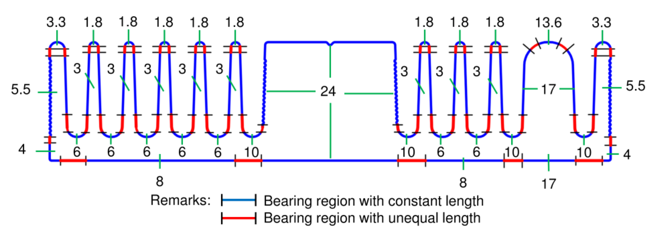
  • The base bearing length is approximated as twice the wall thickness of the extrudate.
  • The bearing length at the thin fin position is multiplied by a coefficient Kc = 0.75, which takes into account the flow obstruction due to the complex geometry.
  • The bearing length at the thick fin position under the port bridge is multiplied by a coefficient Kb = 0.52, which takes into account the flow obstruction due to the port bridge geometry. Thus, the bearing length calculated for this region is about 24 mm.
  • The bearing length at the tip of the extrudate is approximated as 0.6 times the adjacent bearing length [19].

3. Construction of Finite Element Model

Figure 4a demonstrates the 3D assembly model of the components, which is built by CATIA V5R20 software (Dassault Systèmes, Vélizy-Villacoublay, France). Figure 4b illustrates the FE models with different mesh sizes, which will be used for steady-state extrusion simulation with the arbitrary Lagrangian–Eulerian (ALE) algorithm by HyperXtrude 2019 software (Altair Engineering, Inc., Michigan, MA, USA). The entire FE models are divided into six regions, including billet, porthole, welding chamber, pocket, bearing, and profile, as shown in Figure 4b. Rough mesh size is used for the billet region, and fine mesh size is adopted for the bearing region, where severe deformations occur. The tetrahedral element is assigned to the billet, porthole, welding chamber, and pocket regions. The triangular prism element is applied to the remaining regions. The meshing process is carried out automatically as a recommendation by the software with fine mesh level selection. The total number of elements used for this simulation model is approximately 760,000.
The material of the tooling and the porthole die is H13 tool steel. The material used for billet is AA6063 aluminum alloy. Rigid and viscoplastic simulation models are used for the tools and the billet, respectively. The physical and thermal parameters of these materials are the same as those used by the HyperXtrude software library, as shown in Table 1. The continuous equation based on the Sellar–Tegart model, which is widely used in simulations of aluminum profile extrusion [9,10], is applied for the simulation, as described in Equation (1):
σ   = 1 β sin h 1 ( Z ¯ A ) 1 / n
where σ indicates the flow stress of the material; β and A are the extruded material coefficients; n is the exponent; Z is the Zener–Hollomon coefficient calculated by Equation (2):
Z = ε ¯ · e Q / R T
where ε ¯ · is the effective strain rate; Q, R, and T are the activation energy, gas coefficient, and absolute temperature, respectively. The parameters of AA6063 material used in Equation (1) are as follows [19]:   β = 4 × 10 8 m 2 / N ; Q = 1.4155 × 10 5 J / mol ; R = 8.314 J / ( mol .   K ) ; A = 5.90152 × 10 9   s 1 ; n = 5.385.
The stick friction condition is assumed between the extruded material and tools (including dies) with a shear friction coefficient of 1 [8]. The sliding friction condition is assumed between the extruded material and bearing region with a Coulomb coefficient of 0.3 [9]. The heat convection coefficient between the billet and the tooling is 3000 W / m 2 °C [9]. The parameters related to the numerical simulation of the extrusion process are summarized in Table 2.

4. Results and Discussion

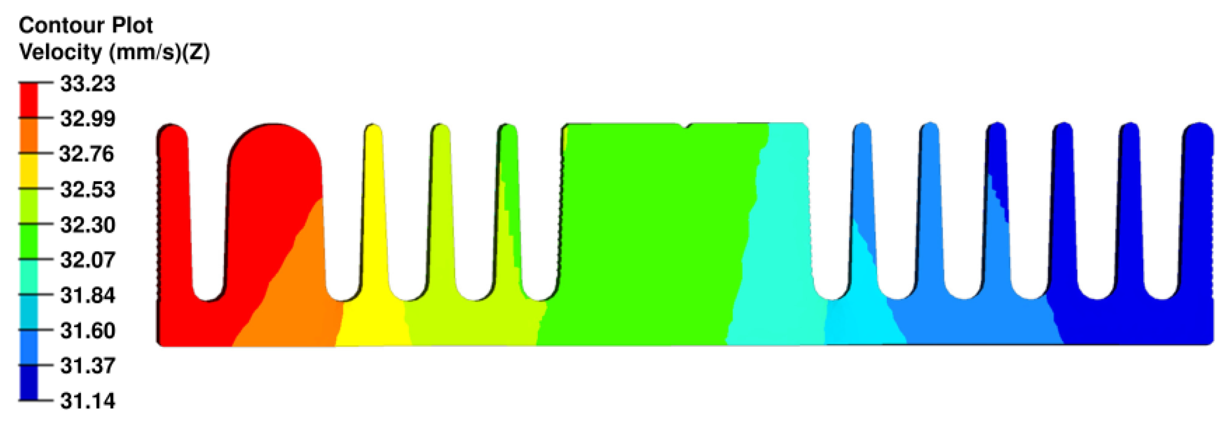
4.1. Velocity Distribution with the Initial Die Design

The flow velocity distribution during extrusion is a crucial factor that determines the success of an extrusion process. Therefore, it is always the first factor to be considered when designing an extrusion die. The quality of velocity distribution can be monitored through several parameters such as the standard deviation of velocity (SDV) [18] or the velocity relative difference (VRD) [20]. In this study, the VRD is used and calculated by Equation (3):
V R D = i = 1 n | V i V a | V a n × 100 %
where Vi is the extrusion velocity at node i on the extrudate; Va is the average velocity calculated from all nodes of the extrudate; n is the number of nodes considered in a cross-section of the extrudate. A total of 3269 nodes was used for the VRD calculations.
In addition, the difference between the maximum and minimum velocities (ΔV) is also used to evaluate the flow balance. This is because geometric defects are likely to occur when significant speed differences arise at any position of the product.
Figure 5 plots the simulated results of flow velocity distribution and the deformation trend of the extrudate. The minimum flow velocities appear in the regions where the metal contacts with the dies and the tools because of the sticking friction effect. The maximum velocities occur at the die orifice region. Nonuniform velocity distribution is generally observed, in which the metal on the left side of the product flows faster than that on the right, especially at the thick fin region. The calculated VRD and ΔV are 4.1% and 4.72 mm/s, respectively. Such uneven velocity distribution will result in bending of product geometry to the right. Therefore, the initial die design needs to be adjusted.

4.2. Adjusting Die Structure

4.2.1. Resizing Porthole

From the simulated flow velocity of the initial die, the metal flows faster on the right-hand section of the profile, which contains a fin with 8.32 mm in thickness. Therefore, the first step of correction here is to reduce the size of porthole 2. In this way, an offset distance of 3 mm is applied for the entrance and bottom edges of this porthole profile. The other geometric parameters of the initial die are fixed. Figure 6 demonstrates the geometry of porthole 2 before and after correction. By applying this correction, the area of porthole 2 is reduced to 1702 mm2 compared to the area of porthole 1 which is 1960 mm2. Consequently, the area ratio of porthole 1 vs. porthole 2 is about 1.15, which approximately equals to the area ratio of the left- and right-side cross-section of the product (about 1.12).
Figure 7 shows the simulated velocity distribution of metal flow with porthole 2 correction. This figure indicates that VRD and ΔV are reduced to 1.76% and 2.09 mm/s, respectively. Hence, the velocity distribution has improved. However, the velocity difference is still relatively high, which may result in a defective extruded product. Therefore, the extrusion die still needs further modification to improve velocity distribution as well as geometric accuracy.

4.2.2. Modifying Pocket Profile

The second step of the welding chamber solution is highly effective for extrusion with porthole die and complex product profiles [18,21]. However, the geometry of the welding chamber usually needs an appropriate design. Therefore, the pocket profile of the lower die is modified here to improve the metal flow distribution. Only the geometry of the pocket profile is further modified in this second step, while the other geometric parameters from the previous modification step are unchanged. Figure 8 shows the modification scheme for the pocket profile of the lower die. In general, the left profile of the pocket is enlarged to reduce the influence of friction and the dead metal zone (DMZ), thereby increasing extrusion speed. On the contrary, the right profile is narrowed at positions of high flow velocities.
Figure 9 presents the simulated velocity distribution using the extrusion die with pocket profile modification. The improvement in flow velocity distribution is clearly observed. The values of VRD and ΔV are reduced to 0.87% and 0.89 mm/s, respectively. With the improvement in flow velocity distribution, deformations at the bottom and left fin regions of the extrudate can be reduced.

4.2.3. Adjusting Bearing Lengths

Adjusting bearing lengths usually takes place at the end of the design process to make some fine-tune adjustments for the die structure, something considered by many authors [3,8]. The main objective of adjusting bearing lengths is to precisely control the product geometry. In this modified step 3, adjusting bearing lengths is performed, while the other die parameters are kept the same as step 2.
Figure 10 demonstrates the distribution of bearing lengths after modification. The general rule for adjusting bearing lengths is based on the velocity distribution in the extrudate. The bearing lengths are reduced at the slower flow velocity areas, whereas they are increased at the faster velocity zones. Accordingly, the bearing lengths on the left side of the product profile are reduced slightly. For the bearing regions on the right side, the bearing lengths at the bottom and the corner of the profile are increased.
Figure 11 shows simulated flow velocity distribution using the die with adjusted bearing lengths. It can be seen that a fairly uniform velocity distribution is obtained. The values of VRD and ΔV are decreased to only 0.75% and 0.78 mm/s, respectively. As a result, the product without geometric defects can be extruded. Hence, the bearing length adjustment solution successfully enhances the flow balancing.

4.3. Effects of the Port Bridge Structural Parameters and the Welding Chamber Height

In the initial die, the parameters of the port bridge and the welding chamber were roughly chosen based on practical experience. Therefore, parameters related to bridge structure such as the port bridge width (W), chamfered bridge, rear tip width (Wt), and welding chamber height (H) (Figure 12), are further investigated to determine the appropriate values. The other parameters in step 3 remain the same. Moreover, the behavior of metal flow with varied die structural parameters is also examined.

4.3.1. Effect of the Port Bridge Parameters

Two types of portholes are considered, including the ones with and without the chamfered bridge. To investigate the effect of the port bridge’s width, W varying from 18 to 26 mm is examined. The parameters Wt and the tip angle are set to 10 mm and 50°, respectively. The chamfer dimension of the port bridge is selected at 4 × 25°, which is commonly used for the die with a container diameter of 130 mm in practical extrusion.
Figure 13 shows the effects of W on ΔV and the required extrusion force. It can be observed that the required extrusion force increases with increasing W. This can be explained by the fact that increasing W will increase the dead material zone (DMZ) under the bridge and reduce the entrance size of the porthole. Moreover, the extrusion force of the porthole die with the chamfered bridge significantly reduces compared to the traditional porthole die, as shown in Figure 13. The reduced amount of extrusion force estimated for W = 18 mm is about 9.7 tons. This is because the size of the DMZ formed before the port bridge is decreased in the die with the chamfered bridge.
Figure 13 also shows that increasing W leads to an increase of ΔV. However, ΔV of both dies with and without chamfered bridges is almost the same.
Figure 14 presents the effect of W on the flatness of the profile nose (ΔD). It is seen that the behavior of ΔD with respect to W is fairly similar to that of ΔV (in Figure 13). The maximum values of the profile nose (Dmax) are found at the 8.32 mm fin area. In the extrusion process, the velocity in the porthole tends to be fast in its center. Increasing W will push the high-velocity zone away from the die center, which leads to increasing the velocity mainly at the 8.32 mm fin area, and therefore Dmax.
From Figure 13, the porthole die with the chamfered bridge is recommended because it reduces the extrusion force significantly while the velocity difference is negligible. In this way, the width W = 18 mm is selected as the appropriate value for this die design.
Figure 15 illustrates the effect of Wt varying from 2 to 10 mm on ΔV, ΔD, and the maximum exit profile temperature. It can be seen that ΔV and ΔD all have the same reduction tendency with increasing Wt. Therefore, the flow balance is improved with increasing Wt. However, the maximum temperature in the exit profile rises slightly. This is because when Wt increases, the size of the DMZ under the bridge is increased (see Figure 16), resulting in a higher degree of metal deformation. Moreover, the increase in exit temperature is also attributed to the flow obstruction caused by the DMZ. Figure 17 depicts the velocity distribution of material estimated for Wt = 2 mm and Wt = 10 mm. The flow velocity under the port bridge with Wt = 10 mm is significantly reduced compared to that with Wt = 2 mm.
In summary, bridge parameters W and Wt significantly influence the velocity distribution of metal during extrusion. The chamfered bridge shows a little effect on the flow balance; however, it can significantly reduce the extrusion force. From the presented results, the proper values of W and Wt for obtaining a good flow balance are 18 and 10 mm, respectively.

4.3.2. Effect of the Welding Chamber Height

In this section, the effects of welding chamber height (H) varying from 9 and 17 mm on the extrusion process parameters are analyzed. Figure 18 shows the behavior of ΔV, ΔD, and maximum exit profile temperature. It can be seen that the effects of H on the extrusion process parameters are totally different compared to the effects of W and Wt represented earlier in Figure 14 and Figure 15. As indicated in Figure 18, the unbalance of flow increases as H becomes very high or very small. H = 13 mm is the best value to achieve the flow balance as both ΔV and ΔD reach their minimum values.
Figure 18 also illustrates that the maximum exit temperature of the profile decreases with increasing H. This is caused by the effect of the DMZ, which exists under the port bridge. For the die with a lower value of H, the DMZ causes greater obstruction to the metal flow at the die opening compared to that of the die with a larger H, as demonstrated in Figure 19. Moreover, reducing H also increases the deformation of metal in front of the die orifice, as shown in Figure 20.
From Figure 18, it can be concluded that the welding chamber height remarkably influences the flow balance. A welding chamber height of 13 mm is the preferable parameter for the present die.

4.4. The Final Die Structure

The ultimate die is obtained after the presented modification steps of die structure. Table 3 summarizes the simulation results corresponding to the die modification steps. Steps 1–3 mainly aim at improving the flow balance of metal (reducing VRD, ΔV, and ΔD), which, however, increases the extrusion force because the extruded material experiences a higher degree of deformation. In the last step, by designing a chamfered bridge structure, the extrusion force is reduced to a minimum, whilst the other parameters VRD, ΔV, and ΔD do not change significantly. Figure 21 presents the 2D layout and 3D model of the proposed extrusion die.
Figure 22 shows the velocity distribution of metal in the initial and proposed dies. It can be seen that the velocity distribution of the proposed die is significantly improved compared to the original one. The deformation of the extrudate with the proposed extrusion die is also reduced.
Figure 23 displays the temperature distribution during the extrusion process of the original and proposed dies. In general, maximum temperatures of proposed and original dies are well approximated. Higher temperature occurs near porthole 2 due to the increase of material deformation in this region.
Figure 24 highlights the distribution of residual stress in the extrudate of the initial and proposed dies. The maximum residual stress in the extrudate with the proposed die is smaller compared to the original die (12.83 MPa vs. 16.19 MPa). High residual stresses are mainly concentrated at the intersection regions between fins with a large wall thickness and the main body of the heatsink, which are caused by the differences in velocity and temperature of the respective regions.

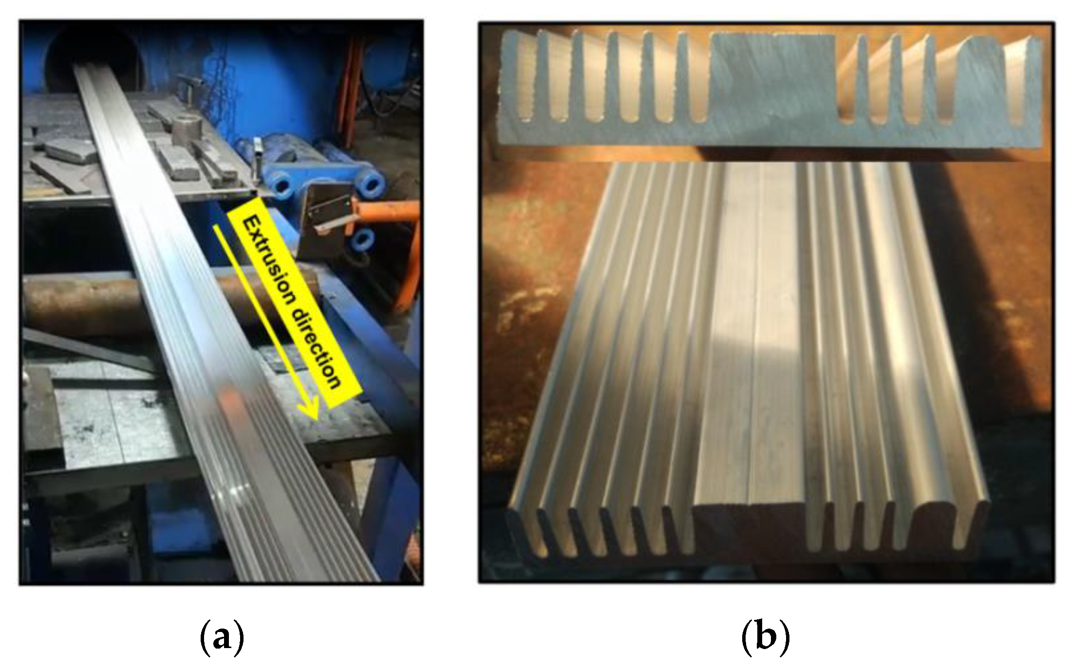
4.5. Extrusion Experiment

To verify the proposed die design, the real porthole die is fabricated according to the geometry parameters of the proposed die. After that, the extrusion experiment is conducted on a 930-ton extruder. Figure 25a shows the experimental extrusion process. Figure 25b presents the final extruded product. It can be seen that a defect-free product was produced. The geometry of the product is generally consistent with the simulation results. To check the geometric dimensions of the extruded product, measurements were carried out using electronic calipers. The deviations in the wall thickness of the product are within the allowable limits of ±0.15 mm, and dimensional errors of the length and width of the product are less than 0.25 mm. Hence, the extrudate meets the requirement for dimensional tolerance.
It is worth noting that the proposed die successfully extrudes for the first time without the need for die modifications. Therefore, the proposed design approach is very useful and reliable. It is also noted here that the effects of die deformation on the dimensional tolerance of the extruded product were assumed negligible. This is because the extrusion process used a porthole die, which reduced the direct impact from the billet to the die orifice. Therefore, the deformation of this die will be smaller than the traditional flat-face dies. Secondly, the extrusion ratio is quite low (=10.73), resulting in a small required extrusion force, and therefore small die deflection. Lastly, the die contains two run-out steps, which support the die opening and increase the die strength. The run-out steps also ensure that the extrudate does not touch the die surface. Hence, die deformation can be minimized.

5. Conclusions

In this study, an appropriate die for extrusion of a complex heatsink aluminum profile with large variable wall thickness was designed. The die design was implemented by combining the existing design experiences and steady-state extrusion simulation with the ALE algorithm. The effects of the structural parameters of the port bridge and the welding chamber height on the metal flow were examined. Experiments were conducted to verify the proposed die. The conclusions are obtained as follows:
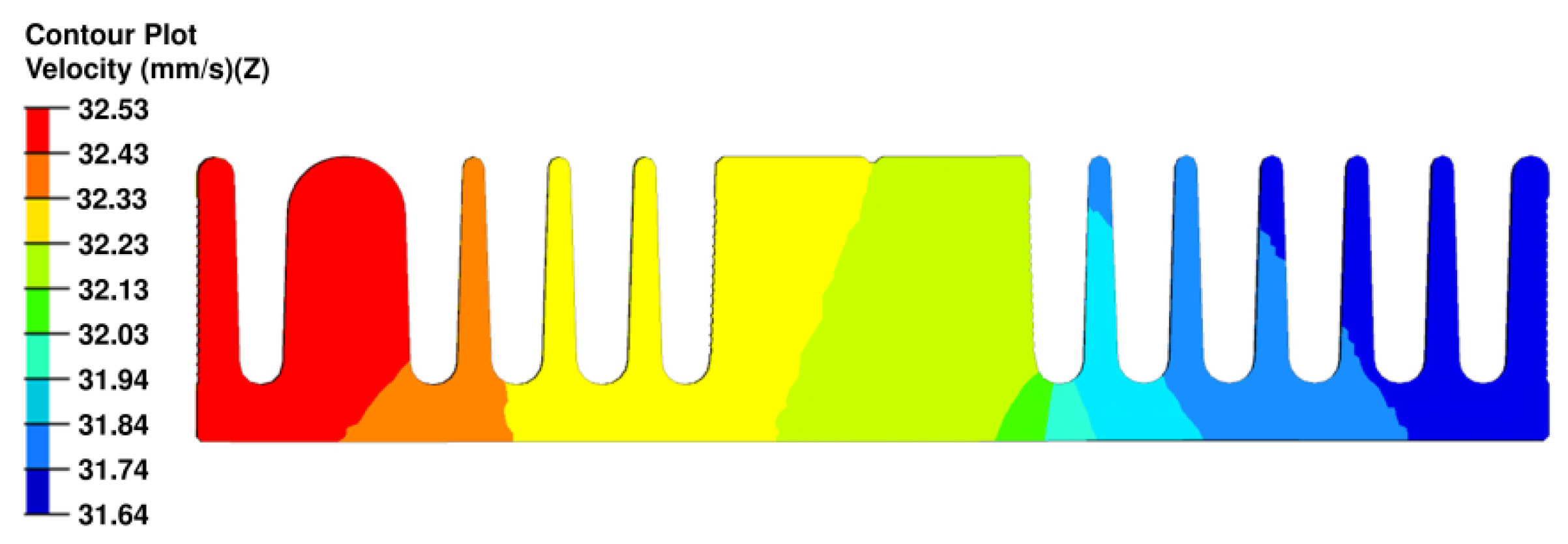
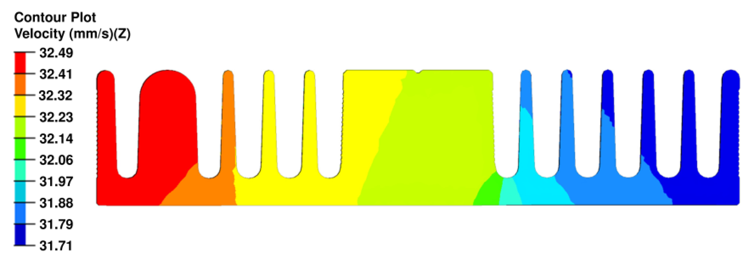
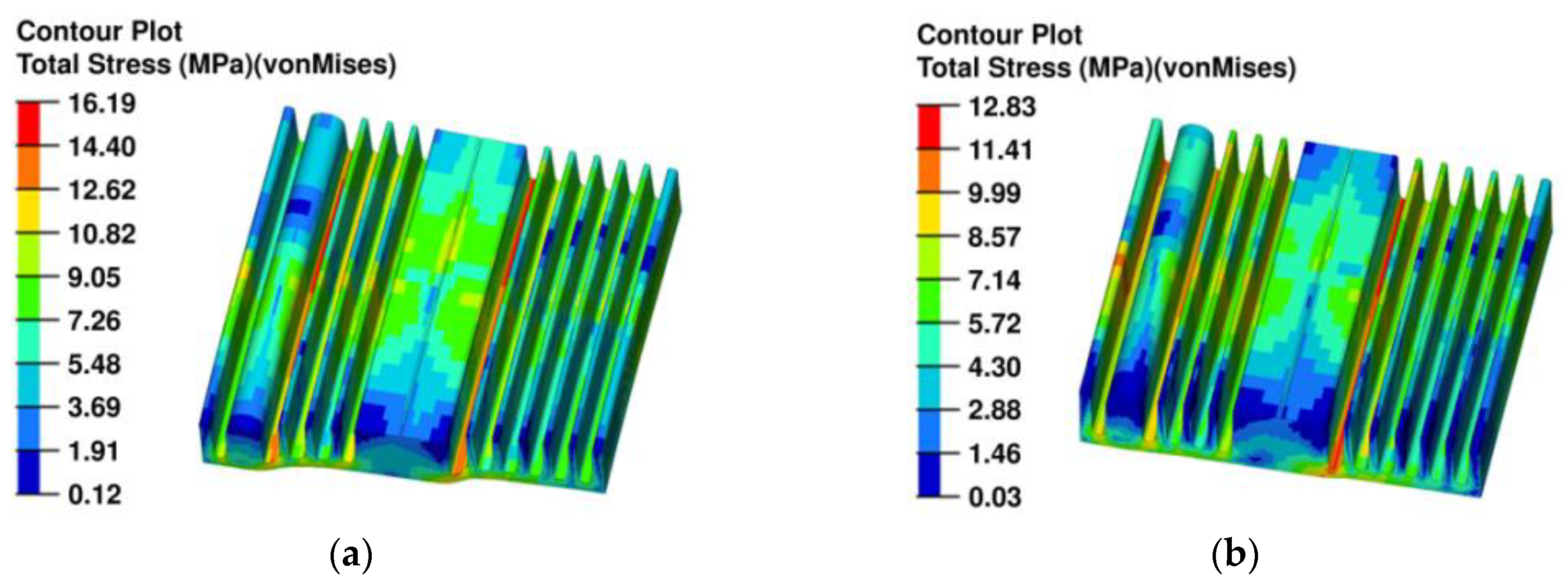
  • The following steps are proposed to obtain suitable porthole extrusion die: (1) resizing the porthole and pocket profiles; (2) adjusting the bearing lengths; (3) modifying the port bridge structure. The simulation results indicate that using the proposed die, the quality of flow balance of metal in the die was improved considerably. Comparing to the initial die, the velocity distribution measures of the proposed solution such as VRD and ΔV are reduced from 4.1% and 4.72 mm/s to 0.82% and 0.86 mm/s, respectively; the required extrusion force and residual stresses in the extrudate are also reduced from 479.55 tons and 16.19 MPa to 477.88 tons and 12.83 MPa, respectively. The maximum exit temperature of the extrudate increases slightly as compared to the initial die.
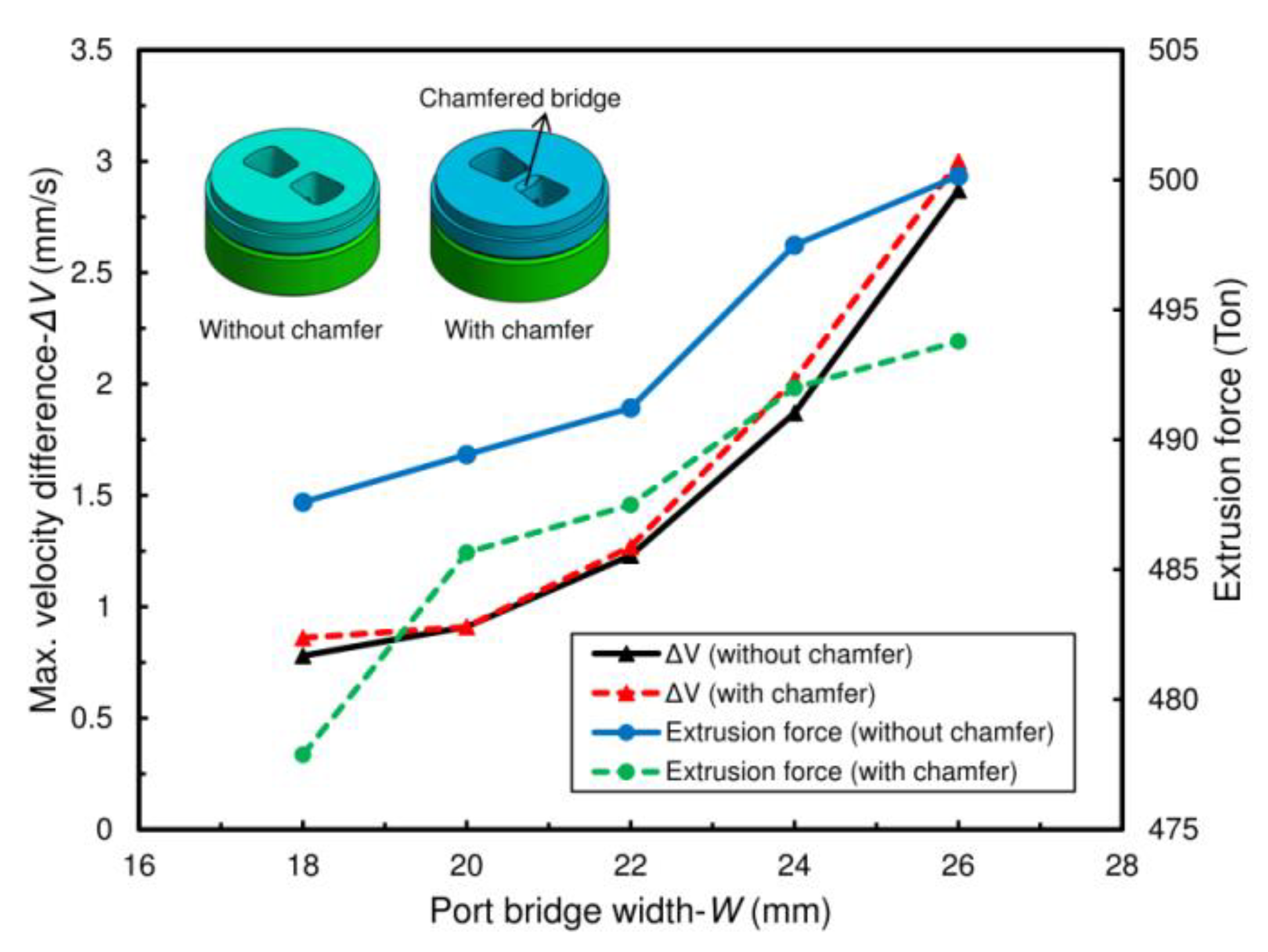
  • The entrance of a porthole with a chamfered bridge significantly reduces the required extrusion force. However, it has a negligible influence on the velocity distribution of flow in the extruded product.
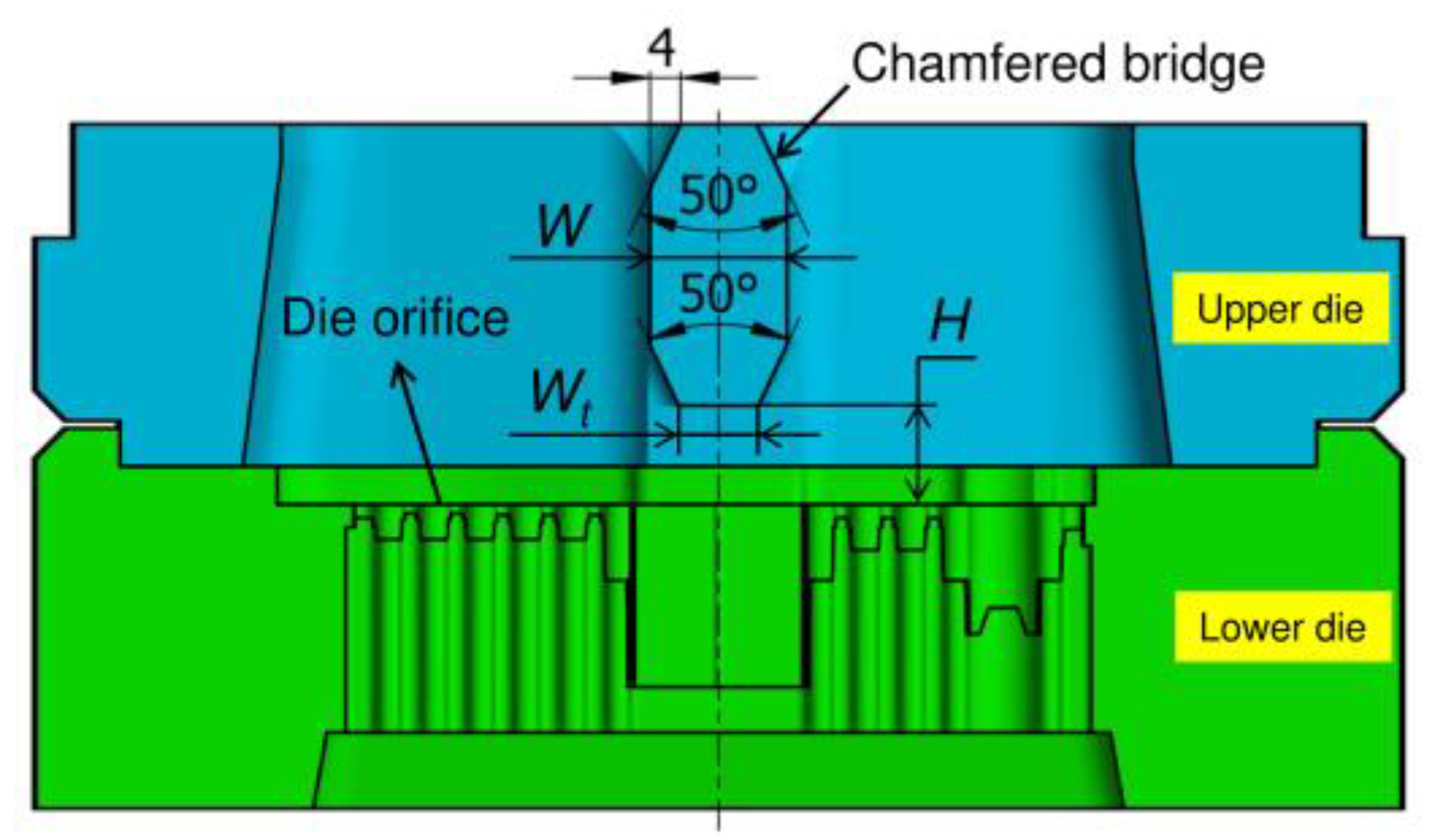
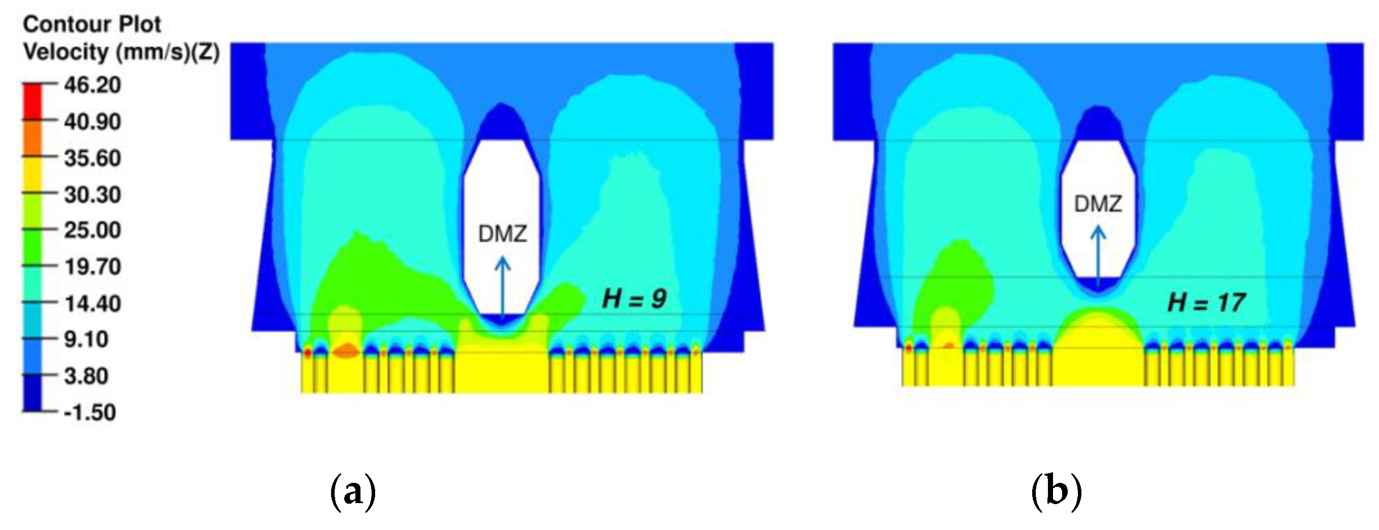
  • The die parameters including the width of the port bridge (W), the rear tip width of the port bridge (Wt), and the welding chamber height (H) all influence the metal flow velocity due to the braking effect of the dead metal zone (DMZ) formed under the port bridge. Moreover, these parameters have different effects on velocity distribution on the extrudate. In particular, the velocity distribution becomes more uniform with increasing Wt from 2 to 10 mm. On the other hand, increasing W from 18 to 20 mm results in uneven velocity distribution in the extrudate. Very high (above 17 mm) or very small (below 9 mm) values of welding chamber height H all have a negative effect on the balance of metal flow.
  • In conclusion, appropriate porthole extrusion die is the key to success of the extrusion of heatsink products with significant wall thickness variation. The main concern in designing this die type is to determine the position and structure of the port bridge, which plays a vital role in balancing the metal flow on the extrudate, especially at the location where the wall thickness is very thick. Although the proposed die is highly suitable for metal flow balance, this die type commonly generates longitudinal weld seams in the extrudates. Moreover, it may cause poor surface quality of the products after anodizing, and higher extrusion force when compared to the flat-face die. Hence, design optimization of porthole dies needs to be extended further.

Author Contributions

T.-T.T. synthesized data, designed and simulated extrusion dies, conducted experiments, and wrote the original manuscript; Q.-C.H. instructed, supervised, and edited the content; V.-C.T. analyzed the results, reviewed, and edited the manuscript. J.-J.S. reviewed and edited the manuscript. All authors have read and agreed to the published version of the manuscript.

Funding

This research was partially funded by the Ministry of Science and Technology, Taiwan, under grant number MOST 108-2221-E-992-066-.

Acknowledgments

The authors would like to acknowledge the financial support from the Ministry of Science and Technology, Taiwan.

Conflicts of Interest

The authors declare no conflicts of interest.

References

  1. Aluminum Extruders Council. Aluminum Extrusion Manual, 4th ed.; Aluminum Extruders Council: Wauconda, IL, USA, 2014; p. 259. [Google Scholar]
  2. Sauer, G.; Ames, A. Extrusion Tooling, 2nd ed.; ASM International: Cleveland, OH, USA, 2006; 592p. [Google Scholar]
  3. Fang, W.; Tang, D.; Wang, H.; Li, D.; Peng, Y. Optimization of die design for thin-walled flat multi-port tube with the aid of finite element simulation. J. Mater. Process. Technol. 2020, 277, 116418. [Google Scholar] [CrossRef]
  4. Lee, J.M.; Kim, B.M.; Kang, C.G. Effects of chamber shapes of porthole die on elastic deformation and extrusion process in condenser tube extrusion. Mater. Des. 2006, 26, 327–336. [Google Scholar] [CrossRef]
  5. Wu, X.; Zhao, W.; Luan, Y.; Ma, X. Numerical simulation and die structure optimization of an aluminum rectangular hollow pipe extrusion process. Mater. Sci. Eng. A 2006, 435, 266–274. [Google Scholar] [CrossRef]
  6. Pinter, T.; Reggiani, B.; Donati, L.; Tomesani, L. Numerical assessment of the influence of process and geometric parameters on extrusion welds and die deformation after multiple-cycles. Mater. Today Proc. 2015, 2, 4856–4865. [Google Scholar] [CrossRef]
  7. Chen, L.; Zhao, G.; Yu, J.; Zhang, W. Evaluation of a pyramid die extrusion for a hollow aluminum profile using FE simulation. J. Mech. Sci. Technol. 2015, 29, 2195–2203. [Google Scholar] [CrossRef]
  8. Liu, Z.; Li, L.; Li, S.; Yi, J.; Wang, G. Simulation analysis of porthole die extrusion process and die structure modifications for an aluminum profile with high length-width ratio and small cavity. Materials 2018, 11, 1517. [Google Scholar] [CrossRef] [PubMed] [Green Version]
  9. Xue, X.; Vincze, G.; Pereira, A.; Pan, J.; Liao, J. Assessment of metal flow balance in multi-output porthole hot extrusion of AA6060 thin-walled profile. Metals 2018, 8, 462. [Google Scholar] [CrossRef] [Green Version]
  10. Chen, L.; Zhao, G.; Yu, J. Effects of ram velocity on pyramid die extrusion of hollow aluminum profile. Int. J. Adv. Manuf. Technol. 2015, 79, 2117–2125. [Google Scholar] [CrossRef]
  11. Donati, L.; Tomesani, L.; Minak, G. Characterization of seam weld quality in AA6082 extruded profiles. J. Mater. Process. Technol. 2007, 191, 127–131. [Google Scholar] [CrossRef]
  12. Yu, J.; Zhao, G.; Chen, L. Investigation of interface evolution, microstructure and mechanical properties of solid-state bonding seams in hot extrusion process of aluminum alloy profiles. J. Mater. Process. Technol. 2016, 230, 153–166. [Google Scholar] [CrossRef]
  13. Güley, V.; Güzel, A.; Jäger, A.; Khalifa, N.B.; Tekkaya, A.; Misiolek, W. Effect of die design on the welding quality during solid state recycling of AA6060 chips by hot extrusion. Mater. Sci. Eng. A 2013, 574, 163–175. [Google Scholar] [CrossRef]
  14. Lee, J.M.; Kim, B.M.; Kang, C.G. A study on the improvement of extrudability for extrusion process of heat sink. In Key Engineering Materials; Trans Tech Publications Ltd.: Kapellweg, Baech, Switzerland, 2004; pp. 487–492. [Google Scholar]
  15. Hwang, Y.; Shen, C. Analysis of plastic flow and die design during extrusion of CPU heat sinks. J. Mater. Process. Technol. 2008, 201, 174–178. [Google Scholar] [CrossRef]
  16. Zhang, C.; Zhao, G.; Chen, H.; Guan, Y. Optimisation design of aluminium radiator extrusion die using response surface method. Mater. Res. Innov. 2011, 15, s288–s290. [Google Scholar] [CrossRef]
  17. Lee, G.A.; Im, Y.T. Analysis and die design of flat-die hot extrusion process 2. Numerical design of bearing lengths. Int. J. Mech. Sci. 2002, 44, 935–946. [Google Scholar] [CrossRef]
  18. Chen, L.; Zhao, G.; Yu, J.; Zhang, W.; Wu, T. Analysis and porthole die design for a multi-hole extrusion process of a hollow, thin-walled aluminum profile. Int. J. Adv. Manuf. Technol. 2014, 74, 383–392. [Google Scholar] [CrossRef]
  19. Truong, T.T.; Hsu, Q.-C.; Tong, V.C. Effects of solid die types in complex and large-scale aluminum profile extrusion. App. Sci. 2020, 10, 263. [Google Scholar] [CrossRef] [Green Version]
  20. Zhang, C.; Zhao, G.; Chen, H.; Guan, Y.; Li, H. Optimization of an aluminum profile extrusion process based on Taguchi’s method with S/N analysis. Int. J. Adv. Manuf. Technol. 2012, 60, 589–599. [Google Scholar] [CrossRef]
  21. Lou, S.; Wang, Y.; Lu, S.; Su, C. Die structure optimization for hollow aluminum profile. Procedia Manuf. 2018, 15, 249–256. [Google Scholar] [CrossRef]
Figure 1. The geometry of aluminum heatsink: (a) the cross-section geometry and main dimensions; (b) the three-dimensional (3D) model (unit: mm).
Metals 10 00553 g001
Figure 2. Design of the initial extrusion die: (a) the 2D layout of the die; (b) the 3D assembly model with the main dimensions of the port bridge (unit: mm).
Metals 10 00553 g002
Figure 3. Schematic of bearing lengths for the initial extrusion die (unit: mm).
Metals 10 00553 g003
Figure 4. Finite element (FE) modeling for steady-state extrusion of aluminum heatsink profile: (a) the 3D assembly model of elements during extrusion; (b) meshing of the regions.
Metals 10 00553 g004
Figure 5. Velocity distribution and deformation trend of the extrudate using the initial die.
Metals 10 00553 g005
Figure 6. Adjustment scheme of porthole 2 of the upper die (unit: mm).
Metals 10 00553 g006
Figure 7. Velocity distribution on the extrudate with the extrusion die after correcting the porthole.
Metals 10 00553 g007
Figure 8. Modification scheme of the pocket profile: (a) the 2D view of pocket profile before and after the change; (b) the 3D model of the lower die after modifying the pocket profile (unit: mm).
Metals 10 00553 g008
Figure 9. Simulated flow velocity distribution using the extrusion die after modifying the pocket profile.
Metals 10 00553 g009
Figure 10. Scheme of recalculated bearing lengths (unit: mm).
Metals 10 00553 g010
Figure 11. Flow velocity distribution using the die with adjusted bearing lengths.
Metals 10 00553 g011
Figure 12. The die geometry with the chamfered bridge. The geometric parameters shown include the port bridge width (W), rear tip width (Wt), and welding chamber height (H).
Metals 10 00553 g012
Figure 13. Influence of W on ΔV and the extrusion force in two types of dies with and without chamfered bridges.
Metals 10 00553 g013
Figure 14. Effect of W on ΔD of the porthole die with the chamfered bridge.
Metals 10 00553 g014
Figure 15. The effects of Wt on (a) ΔV and the maximum exit profile temperature; (b) on ΔD.
Metals 10 00553 g015
Figure 16. Distribution of strain rate of material inside the die: (a) Wt = 2 mm; (b) Wt = 10 mm.
Metals 10 00553 g016
Figure 17. Distribution of velocity inside the die: (a) Wt = 2 mm; (b) Wt = 10 mm.
Metals 10 00553 g017
Figure 18. The effects of H on the extrusion process parameters: (a) ΔV and the maximum exit temperature profile; (b) ΔD.
Metals 10 00553 g018
Figure 19. Distribution of velocity in dies: (a) the die with H = 9 mm; (b) the die with H = 17 mm.
Metals 10 00553 g019
Figure 20. Distribution of strain rate with different H values: (a) H = 9 mm; (b) H = 17 mm.
Metals 10 00553 g020
Figure 21. The proposed die for extrusion of the aluminum heatsink profile: (a) the 2D layout of the proposed die; (b) the 3D assembly model of the upper and lower dies (unit: mm).
Metals 10 00553 g021
Figure 22. Velocity distribution on the extrudate: (a) the initial die; (b) the proposed die.
Metals 10 00553 g022
Figure 23. Temperature distribution during the extrusion: (a) the initial die; (b) the proposed die.
Metals 10 00553 g023
Figure 24. Distribution of residual stress in the extrudate: (a) the initial die; (b) the proposed die.
Metals 10 00553 g024
Figure 25. Extrusion experiments: (a) the aluminum porthole extrusion process of a heatsink profile in practice; (b) the sample of the real product after extrusion.
Metals 10 00553 g025
Table 1. Material properties of the billet and the tools for extrusion simulation.
MaterialDensity (Kg/m3)Heat Capacity (J/(kg °C))Thermal Conductivity (W/m.K)Poisson’s RatioYoung Modulus (GPa)
AA606327009001980.3540
H13787046024.30.35210
Table 2. The parameters used for numerical simulation.
Simulation ParametersValues
Container diameter (mm)130
Billet length (mm)500
Billet temperature (°C)500
Container temperature (°C)450
Die temperature (°C)490
Ram speed (mm/s)3
Extrusion ratio10.73
Table 3. Summary of simulation results of dies corresponding to modifying steps.
StepModificationSimulation results
VRD (%)ΔV (mm/s)ΔD (mm)Extrusion force (ton)
0Initial die design4.104.7212.42479.55
1Reducing porthole1.762.095.76481.88
2Modifying pocket0.870.892.69487.07
3Adjusting bearing lengths0.780.782.38487.59
4Chamfering port bridge0.820.862.58477.88

