Abstract
Spent nuclear fuel (SNF) is nuclear fuel that has been irradiated and discharged from nuclear reactors. During the whole management stages of SNF before it is, in the end, disposed in a deep geological repository, the structural integrity of fuel rods and the assemblies should be maintained for safety and economic reasons. In licensing applications for the SNF storage and transportation, the integrity of SNF needs to be evaluated considering various loading conditions. However, this is a challenging task due to the complexity of the geometry and properties of SNF. In this paper, a simple and equivalent analysis model for SNF rods is developed using model calibration based on optimization and process integration. The spent fuel rod is simplified into a hollow beam with a homogenous isotropic material, and the model parameters thus found are not dependent on the length of the reference fuel rod segment that is considered. Two distinct models with different interfacial conditions between the fuel pellets and cladding are used in the calibration to account for the effect of PCMI (Pellet-Clad Mechanical Interaction). The feasibility of the models in dynamic impact simulations is examined, and it is expected that the developed models can be utilized in the analysis of assembly-level analyses for the SNF integrity assessment during transportation and storage.
1. Introduction
The SNF (Spent Nuclear Fuel), which is the discharged nuclear fuel after irradiation in a nuclear reactor, should be carefully managed due to its strong radioactivity and toxicity. In a so-called open fuel cycle, which is also called a once-through fuel cycle [1], the management program of SNF consists of several stages, namely the temporary storage in the SNF pool, interim storage in a dry storage cask, transportation and final disposal in a deep geological repository, as depicted in Figure 1.
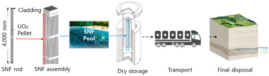
Figure 1.
Management of SNF in the open fuel cycle [1].
The nuclear fuel rod mainly consists of fuel pellets made from uranium oxide encapsulated by tubular cladding made of zirconium-based alloys. The structural integrity of SNF, especially that of the cladding, is important for the safe and economic management of SNF before its final disposal. The cladding serves as the first barrier preventing the release of radioactive materials into the environment. For this reason, the integrity of SNF and cladding should be carefully evaluated during the licensing process of SNF transportation and storage, and it is enforced by safety regulations [2,3,4]. The purpose of such regulations is to protect SNF cladding from any possible sources of degradations and to prevent any gross rupture of SNF to guarantee retrievability and transportability [5].
The structural evaluation of SNF, however, is a very complicated process, due to several reasons. First, the properties and geometry of an irradiated nuclear fuel are different from those of a fresh nuclear fuel, and they possess essential uncertainties due to the random nature of the reactor core environment. In the literature, there are models available for the prediction of cladding properties [6] as functions of burnup, but it should be reminded that they are mostly empirical models based on experimental data and may contain errors. The measurement of the material properties of irradiated claddings or pellets is a very demanding task because it can be performed only in a hot cell environment due to the high radioactivity of SNF. One phenomenon that has not been thoroughly investigated is the bonding between the pellets and cladding, which forms during the irradiation, especially with a high burnup. It is known that this bond makes significant differences in the flexural rigidity and load-bearing capability of the SNF rod [7], but its mechanical properties and characteristics have not been fully understood until now. The effect of the pellet-cladding interaction (PCI) in the reactor environment has been investigated by numerous researchers [8,9,10]. Recently, reports and papers have been published on the effect of PCI on SNF structural integrity under normal conditions of transportation [11,12]. Differences in the impact resistance of high burnup SNF rods caused by PCI under vertical and horizontal drop conditions were quantified [13], and the significance of PCI compared to other uncertain parameters of SNF was analyzed with a parameter study using a design of experiments [14].
The second difficulty in the structural evaluation of SNF loaded in a storage or transport cask arises from the complexity in its shape. The use of a simplified numerical model of SNF is inevitable to avoid excessive computational burden. For commercially utilized casks, around 30 assemblies of PWR fuel can be loaded, and each assembly consists of hundreds of fuel rods. Thus, modular approaches [7,15,16,17,18,19,20,21,22,23] have been utilized where models of SNF assemblies with fuel rods with different levels of fidelity are built to quantify the forces exerted on the SNF assembly with fuel rods under design basis accident conditions, and to finally obtain the detailed behavior of fuel rods. In assembly level analyses, the SNF rods are often simplified into beams with degenerated section and material properties. However, this model simplification procedure is not simple due to the complicated composite behavior of fuel pellets and cladding with uncertain interfacial conditions. Thus, conventional approaches rely on conservatism to neglect the structural resistance of fuel pellets, while their mass is solely included in the calculation as a source of loading. In the work of Lee and Kim [24], the material properties of the equivalent beam model of the SNF rod was found using optimization, considering two distinct interfacial conditions. It was shown that the proposed approach produces more reasonable degenerated models compared to the conventional approach. However, the approach shows a drawback insofar as the calibrated material property of the beam depends on the length of fuel rods’ segments considered.
In this work, equivalent beam models of SNF rods are developed using parameter calibration based on optimization. Efforts are made to make the models independent of the length of the reference fuel rod segment. For this, detailed finite element models of SNF rods are constructed with the material properties predicted by available models in the literature. Two different interfacial conditions are implemented to account for the two extreme cases of PCMI. An integrated optimization is performed to find the best setting of beam material and cross section parameters that minimize the discrepancies in the structural response of the simplified beam model and the original detailed model. The beam models thus found are examined in dynamic impact simulations to check their applicability in the assessment of fuel rod failure under accident conditions.
2. Material Properties of Target Fuel Rod
2.1. Reference Fuel
Table 1 describes important parameters of the reference fuel assembly considered in this work. This fuel assembly is the same one that is considered in [24]. It is noted that the SNF with a burnup greater than 45 GWd/MTU is categorized into high burnup fuel (HBF), whose characteristics are distinctively different from those of low burnup fuels. In this work, only high burnup fuels are considered.

Table 1.
Specifications of the fuel rod and assembly [24].
2.2. Mechanical Properties of Irradiated Fuel Rod
One important issue which has been extensively investigated in the field of SNF management is the characterization of the material properties of HBF cladding. The properties are determined by many factors related to the reactor operation and the environments to which SNF is exposed after its discharge from the reactor. Researchers of PNNL (Pacific Northwest National Laboratory) [6] developed a model which calculates the mechanical properties of irradiated cladding and fuel pellets as functions of various factors such as temperature, neutron fluence, hydrogen contents, burnup, and so on. This model is based on extensive data obtained from hot cell tests on the irradiated fuel and cladding. In this work, the PNNL model is utilized for the calculation of the mechanical properties of cladding and pellets of the reference SNF. A very routine management history starting from the SNF pool in the reactor site to the dry storage of up to five years was considered. The peak cladding temperature (PCT) is maintained at around 30 °C in the reactor pool and increases shortly up to 400 °C during the vacuum drying stage. It gradually decreases during the storage period due to the reduction of decay heat generation. In approximately five years of storage, the PCT of the reference SNF reaches around 300 °C. Important parameters for the calculation of mechanical properties of fuel cladding are summarized in Table 2 for reference.
Table 2.
Input parameters for the calculation of mechanical properties of irradiated cladding [24].
The PNNL model describes the stress-strain relationship of irradiated Zircaloy with Hook’s law for elastic deformation and with the power law for plastic deformation, as follows:
where is the true stress (MPa), is the true strain, and is the Young’s modulus (MPa). In Equation (2), is the strength coefficient (MPa), is the strain rate (/s), is the strain rate exponent, and is the strain hardening exponent. The yield stress is given as the non-zero intersection of Equations (1) and (2), as follows:
The ultimate tensile strength can be obtained using Equation (1) by putting the summation of the maximum elongation and elastic strain at yield into . All the parameters in Equations (1)–(3) are provided in [6] as functions of various parameters. With the entry data, including those listed in Table 2, the material parameters relevant for the reference SNF are calculated and summarized in Table 3. Figure 2 is the generated true stress-strain curve of the reference SNF cladding. It is noted that this model does not predict the failure of cladding and can be applied only to the cladding with circumferential hydrides. The strain failure limit of HBF cladding ranges between 1% and 4% [25], and 1% is chosen in this work to be on the conservative side.
Table 3.
Mechanical parameters of the fuel rod model [24].
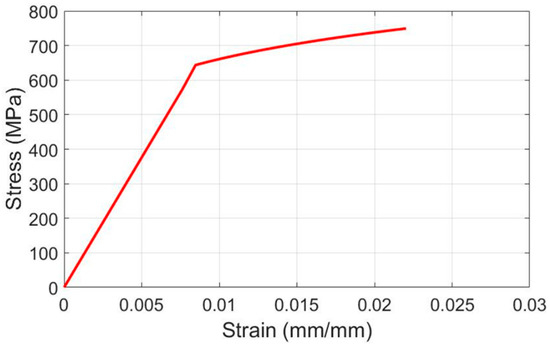
Figure 2.
Stress-strain curve of Zircaloy-4 cladding obtained by the PNNL model [6].
The irradiated UO2 pellets are considered as an elastic material, and their mechanical properties are obtained from [7,11]. It is well-known that the imperfections in the UO2 pellets, especially cracks, can make significant variations in the mechanical properties of pellets. Although the cracks are not modeled explicitly in this study, their effects are considered in the estimation of the mechanical properties of pellets, as stated in [11]. It is believed that the errors and uncertainties resulting from the pellet properties can be quantified and reduced upon provision of more data.
3. Equivalent Beam Model of Spent Nuclear Fuel Rod
3.1. Objective of Model Simplification
The strategy of model simplification can vary depending on the usage of the model. For example, the simplified model or equivalent model for the mechanical vibration analysis cannot be the same as the one for the dynamic impact analysis even for the same target object. In this work, an equivalent model of the SNF rod for the dynamic impact analyses is developed considering the conditions of transportation accidents. The purpose of the model is the accurate prediction of fuel rod failure under the same critical impact load derived from the detailed model, with a much lower computational cost. For this, a detailed finite element model of the SNF rod is constructed and static analyses are performed to capture the fuel rod response under a static load and to find the critical load that results in the failure of fuel rods. Then, these results are utilized in the model calibration procedure to generate an equivalent beam of SNF under a lateral impact load. Unlike the model developed in [24], it is endeavored to develop an equivalent model whose properties are not dependent on the length of the reference fuel rod segment.
3.2. Detailed Finite Element Model of Fuel Rod Segment
A segment of a fuel rod with 35 fuel pellets is taken as the reference for the model simplification. The length is 397 mm. Finite element models for this fuel segment are constructed using hexahedral elements, as shown in Figure 3. Since the interfacial behavior between pellets and cladding is important, the pellets are modeled with enough geometrical details and mesh density. Element C3D8I of ABAQUS/Standard [26] is used to better capture the bending behavior. To save computational time, a half model with a symmetry boundary condition is utilized. A total of 418,906 elements with 346,080 nodes are used in the model.
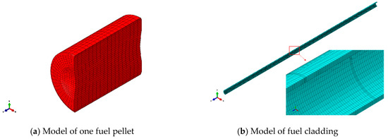
Figure 3.
Detailed finite element model of the reference fuel rod segment.
In a fresh fuel rod, there is a small gap between the pellets and cladding filled with inert gas such as Helium. The size of the gap is 165 μm in diameter for the reference fuel type. During the reactor operation, this interfacial condition changes due to chemical and mechanical interactions caused by high temperature, pressure, and irradiation. This change becomes more prominent as the burnup increases, and normally the gap is filled with fused material in HBF as the pellets and cladding are fused together during the reactor operation [8,9,10]. In the work of Wang et al. [11,12], cyclic loadings were applied to the irradiated fuel rod specimens in the hot cell, and numerical simulations were performed to characterize the behavior of composite fuel rods under mechanical loadings. It was revealed that the interfacial bond makes a significant contribution to the flexural rigidity of fuel rods and the external bending load, and the bond breaks as the loading cycle progresses. Unfortunately, the characteristics of this bond have not been well investigated, and there is no data with enough details that can be referred to in order to describe the behavior of this bond in a quantitative manner. For this reason, two extreme cases are considered in this study as shown in Figure 4. In one case, all the pellets are bonded to the inner surface of the cladding, and in the other case the pellets are separated from and in contact with the cladding. These conditions are implemented by imposing different surface-to-surface interactions in finite element analyses. To simulate the condition where the outer surfaces of the pellets are boned to the inner surface of the cladding, the degrees of freedom of the mating surfaces are tied together. In the other case, surface-to-surface contact with zero friction is assigned between the pellets and cladding. These conditions are implemented with relevant keywords in ABAQUS/Standard. In real HBF, bonds also form between fuel pellets, but these bonds are not considered in this work. Thus, all the pellets are in contact with each other without friction.
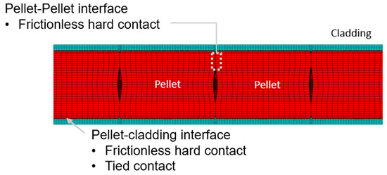
Figure 4.
Interfacial conditions between pellets and cladding.
3.3. Loading, Boundary Conditions for Static Analyses of Fuel Rod Segments
Pure bending, as shown in Figure 5, is imposed onto the reference fuel rod segment for the static analysis. The ideal scenario is that the loading is representative enough of the actual loading that a SNF rod experiences in reality. In a lateral impact, the fuel rod experiences complicated loadings such as distributed shear force due to inertia, pinch load exerted by the supporting grids, pinch load which results from the collision with other fuel rods, and so on. However, the deformation mostly incurred by the above-mentioned loading conditions is the bending, and it is well known that the bending moment dominates the bending behavior for long and slender members. In a pure bending, the loading condition is consistent throughout the length of the fuel rod, and it is expected that material properties derived from this loading can be independent of the length of the fuel rod segment considered. The nodes at both sides of the end cross sections are connected to reference points by rigid beams (Figure 5). Bending moment are imposed onto these two reference points, and the critical value of their magnitude is sought, which results in the failure of the cladding. A detailed discussion of this is provided in the following section.
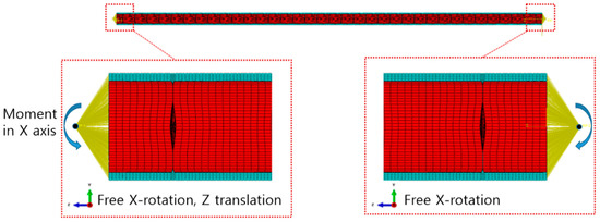
Figure 5.
Loading and boundary condition of single fuel rod segment analyses.
The degree of freedom of one reference point is constrained except in the x directional rotation, and for the other reference point the z directional translation is additionally permitted, so that the fuel rod can bend freely without rigid body motions, as shown in Figure 5.
3.4. Results of Static Analyses for the Fuel Rod Segments
Through static analyses using detailed models, the force-displacement curves of the fuel rod segments and the critical bending moments that yield the failure of the cladding are obtained for bonded and de-bonded interfacial conditions, respectively. It is known from numerous experimental data that the cladding of high burnup SNF fails under plastic strain between 1% and 4% [25]. The tests used to generate those data are the pressurized tube tests, and the stress states of cladding under those experiments are uniaxial or biaxial tension. The fuel pellets were all removed by defueling operations before the tests, and the complicated stress states which occur in real SNF rods due to the PCMI could not be reflected in those test data. The data regarding the failure criteria of irradiated cladding under more complicated 3-D stress states is hardly available. For this reason, the plastic bending strain computed from the centerline curvature of the fuel rod is utilized as a measure to determine the failure of cladding. The curvature can be calculated from the coordinates of three points located along the centerline of the fuel rod by solving Equation (4), and the total strain and the plastic bending strain can be calculated using Equations (5)–(6):
In the above equations, , , and are the coordinates of three points located along the centerline of the fuel rod, and denotes the coordinates of the center of the curvature. is the outer diameter of the fuel rod.
The threshold value of plastic strain is chosen as 1% to be on the conservative side. From the static analyses using ABAQUS, the critical bending moment for the fuel rod segment with a fully bonded interface is calculated as 31,919 N⋅mm, while that of the fully de-bonded case is calculated as 27,975 N⋅mm. The deformed shape and stress contours are shown in Figure 6 and Figure 7. Different patterns of stress distribution are observed for the two cases. The bending moment versus maximum deflection of the fuel rods is plotted in Figure 8 and Figure 9. The flexural rigidity of fuel rods can be calculated from these moment-deflection curves, and the effective Young’s moduli are obtained assuming that the fuel rods are solid circular beams. The effective Young’s modulus of the fully bonded fuel rod is 110 GPa, while that of the fully de-bonded fuel rod is 35 GPa.
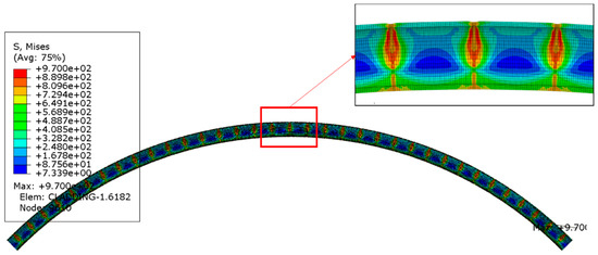
Figure 6.
Deformed shape and stress distribution of cladding (fully bonded interface).
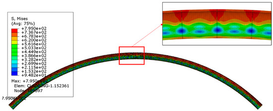
Figure 7.
Deformed shape and stress distribution of cladding (fully de-bonded interface).
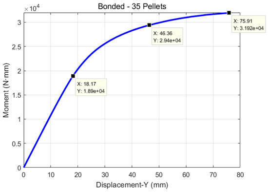
Figure 8.
Moment versus maximum displacement diagram (fully bonded case).
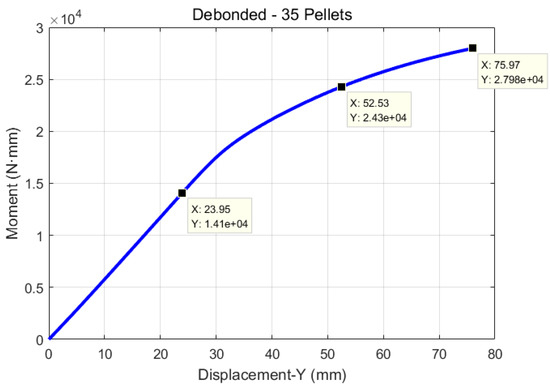
Figure 9.
Moment versus maximum displacement diagram (fully de-bonded case).
3.5. Calibration of Material and Section Parameters of Simplified Beam Model
For numerical simplicity, the spent fuel rod is degenerated into a beam made of homogeneous isotropic material with an annular cross section. The material properties and cross section parameters of this beam should be carefully chosen to make the mechanical responses of this beam close enough to those of the original detailed model discussed in Section 3.4. The ideal situation is that the behavior of this beam is identical to that of the detailed model throughout the whole ranges of loading. However, to find such model parameters may not be practically possible, and the existence of such a solution is not guaranteed. Thus, it is aimed in this work to have the simplified model fail under the critical load for the detailed model derived in Section 3.4, and the failure should be predictable with the same criteria as the detailed model. Because the failure criterion adopted is the plastic strain calculated from the curvature and the curvature is calculated from the displacement of three points along the centerline of the fuel rod, it is endeavored to make the equivalent beam model have the same displacement as with the detailed model for given moment loadings. By doing this, it is also expected that the load transferred from the collision with other fuel rods or a fuel basket in a cask can be simulated accurately because the beam model possesses the same flexural rigidity as with the detailed model. Three points along the moment-deflection curves are chosen for calibration, as depicted in Figure 9 and Figure 10 as squares with their coordinates. The leftmost point is chosen in the elastic region, and the rightmost point corresponds to the critical moment that yields a 1% plastic strain along the length of the fuel rod. The center point is arbitrarily chosen in the plastic region between the leftmost point and the rightmost point. The values of moments at these points are denoted by , , and , respectively, for future reference. The subscripts , , and mean elastic, plastic, and critical. The material model introduced in Section 2.2 is utilized to describe the material property of the equivalent beam.
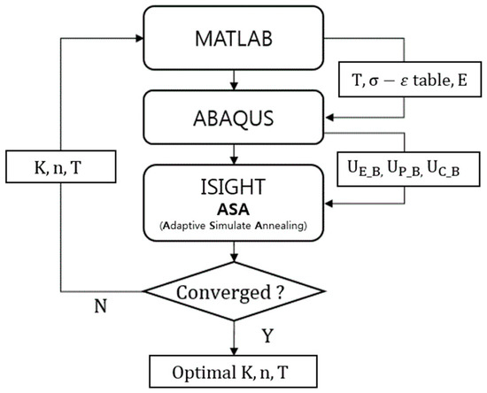
Figure 10.
Flowchart of the parameter calibration for the equivalent beam models of SNF.
The calibration parameters considered are the thickness of the annulus in the beam cross section, strength coefficient , and the hardening exponent in the material model. The calibration procedure is formulated into an optimization problem as follows:
where , , and mean the maximum displacement of the model under , , and , respectively. The subscripts and denote the detailed model with solid elements and the equivalent model with beam elements, respectively. The values of , , and are predetermined as discussed in the previous section for both fully bonded and fully de-bonded cases (Figure 8 and Figure 9).
The solution of the above problem is found by integrating several software. ABAQUS is used for the calculation of , , and for the given beam parameters , , and . An optimization algorithm, adaptive simulated annealing (ASA) [27], is used to find optimal values of the calibration parameters, and MATLAB is used to generate a stress-strain table from the calibrated parameter values found by ASA. It is then input into ABAQUS for static analyses of the beam model. The Young’s modulus is pre-determined from the moment-curvature curves obtained by the detailed models in advance of the calibration procedure, and the density of the beam is determined in such a way that the beam model possesses the same mass as the detailed model. The flowchart of the solution procedure is illustrated in Figure 10. The commercial software iSight [28] is utilized for the process integration and optimization.
The optimization procedure successfully found the solutions, and the results are summarized in Table 4. In the Table, the (dev. %) means the percentage difference between the values of the displacement calculated from the detailed models and those calculated from the simplified beam models. The moment-curvature curves of the beam models compared with those of the detailed solid models are shown in Figure 11. It is observed that the curves of the simplified beam models match well with those of the detailed model in the elastic region and at the critical points for both the fully-bonded and fully de-bonded cases. On the other hand, they show considerable discrepancies in the intermediate plastic region. This happens because the ASA puts more priority in reducing the discrepancy of the displacement under the critical loading, since the difference in and is dominant in the calculation of the objective function in Equation (7).
Table 4.
Results of the beam model parameter calibration.
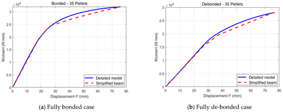
Figure 11.
Comparison of the moment-curvature diagrams of the detailed model and simplified model.
3.6. Applicability of Simplified Models in Analyses of Fuel Rods with Various Lengths
The beam properties obtained in the previous section are applied to fuel rod segments with different lengths to check the validity of the calibrated parameters in the analyses of fuel rods with different lengths. Separate models for fully bonded cases and fully de-bonded cases are constructed, and the same boundary condition and loading are applied as those for the reference fuel rod segments (Figure 5). The results are summarized in Table 5. It is observed that the behavior of the detailed models match exactly with those of the simplified models using the parameters found in Section 3.5, regardless of the lengths of the fuel rods. Although the behavior of the fuel rods varies according to their lengths, it can be predicted, using simplified models with a single set of parameters. Thus, the applicability of the simplified model found in Section 3.5 to fuel rods with various lengths is well demonstrated.
Table 5.
Application of the calibrated beam parameters to different lengths of fuel rod segments.
4. Applicability of Developed Models in Dynamic Impact Simulations
4.1. Models for Impact Simulation and Impact Conditions
In Section 3, simplified models of high burnup SNF were developed using static analyses. The feasibility of using those models in dynamic simulations considering the accident conditions involving impact is examined in this section. For this, the same fuel rod segment in Section 3 is considered, and models for impact analyses are constructed using solid elements for the detailed models and using beam elements for the simplified models. The solid model of the fuel rod segment is identical with that used in the previous section, and blocks of Zircaloy are attached to both ends of the segment to impose the simply supported boundary condition (Figure 12). The simplified model using beam elements is constructed in the same manner (Figure 13). The motions of the Zircaloy blocks are constrained, allowing only the vertical translation. For the detailed model, the symmetry boundary condition is also imposed in order to use the half model. The reference points in the detailed model (Figure 5) are tied to nodes of Zircaloy blocks, while the end nodes of the simplified beam model share the translational degree of freedom with nodes of Zircaloy blocks, as shown in Figure 12 and Figure 13.
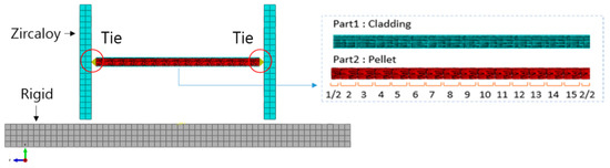
Figure 12.
Model for the dynamic impact analysis (Detailed model).
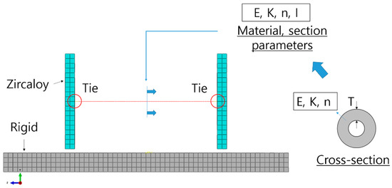
Figure 13.
Model for the dynamic impact analysis (Simplified model).
The ground to which the fuel rod models are impacting is a rigid body. To check the correlation of simplified model and detailed model under a range of impacting forces, a number of drop heights from 0.5 m to 4.0 m are tried. The drop height is converted into impact velocity, as in Equation (8) and then input into ABAQUS/Explicit as the initial condition of the dynamic analyses:
In all cases, the maximum vertical deflection of the fuel rod segments and the plastic strain are calculated by analyzing the time history of the displacements of three locations on the fuel rod segments with Equations (4)–(6). The plastic strain is calculated from the maximum curvature of the fuel rod during the impact.
4.2. Results and Discussions
Dynamic impact simulations are performed using ABAQUS/Explicit with models described in the previous section. Eight drop simulations with different initial velocities are carried out for a fully bonded case and fully de-bonded case, respectively, and the results are summarized in Table 6 and Table 7. The critical drop heights, which result in a plastic strain of 1.0% in the detailed models, are calculated with additional simulations based on linear interpolation. The critical drop height for the fully bonded fuel rods is calculated as 3.05 m, while that of the fully de-bonded fuel rods is 2.63 m. For all the simulation cases, the results of the simplified beam model are compared with those of the detailed models, and it is recognized that the displacement prediction shows a good correlation while the plastic strain prediction contains considerable deviations. The deviations in the maximum displacement for the fully bonded fuel rod are less than 4.5% in the whole range of drop heights, while those for the fully de-bonded fuel rod are up to 18%. The deviation of the plastic strain prediction under the critical drop height is 27% for the fully bonded case and 16.3% for the fully de-bonded cases. It is noted that these deviations were eliminated in the static analyses through beam parameter calibration. During the impact, the deformation is transient and caused by mechanical vibration and stress waves as well as by rigid body deceleration. This dynamic effect was not considered in the calibration procedure, and it is supposed that this nature of static and dynamic deformation is the major reason for the differences in the behavior of the detailed model and the beam model. The pellets are much heavier than the cladding, and the different mass distributions of the detailed model and the beam model can be another source of the deviations. The pellets in the fully de-bonded fuel rods have more degrees of freedom relative to the cladding than in the fully bonded case, and their inertia effect makes a bigger difference in the behavior of the simplified model and the detailed model. Since the plastic bending strain contains considerable deviations from those calculated by the detailed model, a new measure such as a dynamic amplification factor might be necessary for the simplified model to be used in the prediction of fuel rod failure.
Table 6.
Results of the impact analyses for the fully bonded case.
Table 7.
Results of the impact analyses for the fully de-bonded case.
In Table 8, the time history of the maximum deflection is plotted under various drop heights, including the critical ones. Differences in the dynamic behavior caused by the different interfacial conditions are well observed. The simplified models capture such differences well, although they do not show a perfect correlation with the results of the detailed models. As explained beforehand, the displacement prediction is more accurate for the fully bonded case than for the fully de-bonded case. However, the vibration characteristics of the detailed models, such as the vibration period and damping, are not well captured by the beam models for both cases. To calibrate the model parameters for vibratory responses, a different strategy is necessary, taking into account a different set of calibration parameters, such as material damping and so on. In the current scope of this work, an accurate prediction of the maximum displacement during the impact is most important. The discrepancy in the dynamic behavior of the simplified models and the detailed models is also attributed to the different mass distributions within the cross section of the models. Because the simplified models are made of one homogeneous isotropic material, the mass distribution in the cross section cannot be made the same as that of the detailed models. This makes no difference in the static analyses, while it does in the dynamic simulations. To overcome this, a different strategy of model calibration might be necessary, such as calibrating material parameters using dynamic simulations.
Table 8.
History of the maximum deflection of fuel rods calculated by dynamic impact simulations.
5. Discussions and Conclusions
Equivalent beam models of high burnup SNF rods are developed by an integrated model calibration procedure. It is intended that the developed models be used in the assessment of fuel rod integrity under drop impact accidents without resorting to detailed models of SNF rods. Two separate models are utilized in the calibration procedure to account for two extreme conditions of interfaces between the fuel pellets and cladding because it was well revealed by previous research that the interfacial condition makes a significant difference in the fuel rod behavior and resistance to failure. It was demonstrated that the simplified models thus developed successfully reproduced the distinct behavior of fuel rods caused by the different interfacial conditions. It was also shown that the proposed models were applicable irrespective of the length of the fuel rod segments under consideration.
The calibration procedure is based on static analyses, and the applicability of the proposed models in a dynamic impact simulation is examined. Overall, the simplified models mimic the dynamic behavior of the detailed models, but they do not show a perfect correlation, especially in the calculation of the plastic strain, which is important for the failure prediction. Issues including this problem are discussed below:
- -
- In this work, only the horizontal or lateral loading cases are considered. It is known that the horizontal and vertical drops are two representative drop orientations of the SNF transportation cask and that the horizontal drop is more bounding than the vertical one [14,15]. Thus, the use of the developed models in other drop orientations would produce rather conservative results. The applicability of the proposed method and models in other drop orientations needs to be carefully investigated in order to demonstrate the usefulness of the current work for SNF transportation applications. This is the topic of the authors’ future research.
- -
- The calibration procedure is based on an assumption that the fuel rod failure can be predicted via the plastic strain calculated by the curvature rather than via the local strain components. The validity of this assumption cannot be checked right away due to the lack of supporting data. However, the procedure proposed in this work can be used with minimal modifications with a different measure of fuel rod failure.
- -
- In this work, two extreme cases of interfacial conditions were considered. The actual behavior of the interfacial bonding might be intermediate; the bond may break during the loading processes. It is expected that the results of this study provide the bounds of the effective properties of the high burnup fuel rods.
- -
- Although the proposed simplified models show perfect agreements with the detailed models in predicting the maximum displacement and plastic strain in static analyses, they show considerable discrepancies in dynamic impact simulations. To overcome this issue, a compensating factor can be introduced for the accurate prediction of fuel rod failure. This is a topic which needs further investigations.
- -
- There exist many types of uncertainties in the properties and geometries of SNF rods, and they need to be adequately considered for a more realistic and reliable prediction of fuel rod behavior. The approach proposed in this work is purely deterministic but can be combined with well-established uncertainty propagation methods in the literature to quantify the uncertainties in the calibrated model parameters and the resulting behavior of SNF rods and to find their error bounds.
Author Contributions
S.L. is the principal investigator of this research and contributed to the research planning, verification of the results and the manuscript writing. S.K. contributed to the survey of relevant literature, scientific computing using ABAQUS and preparation of data, figures and tables in the manuscript. All authors have read and agreed to the published version of the manuscript.
Funding
This research was funded by Keimyung University grant number 20180342. And The APC was funded by Keimyung University.
Acknowledgments
This research was supported by the Bisa Research Grant of Keimyung University in 2018.
Conflicts of Interest
The Authors declare that there is no conflict of interest.
References
- Ojovan, M.I.; Lee, W.E.; Kalmykov, S.N. An Introduction to Nuclear Waste Immobilization; Elsevier: Amsterdam, The Netherlands, 2019. [Google Scholar]
- U.S. Nuclear Regulatory Commission. Licensing Requirements for the Independent Storage of Spent Nuclear Fuel, High-level Radioactive Waste, and Reactor-related Greater than Class C Waste, Rules and Regulations, Title 10, Part 72; US NRC: Washington, DC, USA, 2010.
- U.S. Nuclear Regulatory Commission. Packaging and Transportation of Radioactive Material, Rules and Regulations, Title 10, Part 71; US NRC: Washington, DC, USA, 2009.
- IAEA Safety Standard. Regulations for the Safe Transport of Radioactive Material, 2012 ed.; Specific Safety Requirements No. SSR-6; IAEA: Vienna, Austria, 2012. [Google Scholar]
- U.S. Nuclear Regulatory Commission. Cladding Considerations for the Transportation and Storage of Spent Fuel, Interim Staff Guidance-11 Rev. 3; US NRC: Washington, DC, USA, 2003.
- Geelhood, K.J.; Beyer, C.E.; Luscher, W.G. PNNL Stress/Strain Correlation for Zircaloy (PNNL-17700); Pacific Northwest National Laboratory (PNNL): Richland, WA, USA, 2008. [Google Scholar]
- Adkins, H.; Geelhood, K.; Koeppel, B.; Coleman, J.; Bignell, J.; Flores, G.; Wang, J.A.; Sanborn, S.; Spears, R.; Klymyshyn, N. Used Fuel Disposition Campaign, Used Nuclear Fuel Loading and Structural Performance under Normal Conditions of Transport—Demonstration of Approach and Results on Used Fuel Performance Characterization (FCRD-UFD-2013-000325); U.S. Department of Energy: Washington, DC, USA, 2013.
- Cheon, J.S.; Lee, B.H.; Koo, Y.H.; Oh, J.Y.; Sohn, D.S. Evaluation of a pellet-clad mechanical interaction in mixed oxide fuels during power transients by using axisymmetric finite element modeling. Nucl. Eng. Des. 2004, 231, 39–50. [Google Scholar] [CrossRef]
- Marchal, N.; Campos, C.; Garnier, C. Finite element simulation of Pellet-Cladding Interaction (PCI) in nuclear fuel rods. Comput. Mater. Sci. 2009, 45, 821–826. [Google Scholar] [CrossRef]
- Kim, H.C.; Seo, S.K.; Lee, S.U.; Yang, Y.S. Development of NUFORM3D module with FRAPCON3. 4 for simulation of pellet-cladding mechanical interaction. Nucl. Eng. Des. 2017, 318, 61–71. [Google Scholar] [CrossRef]
- Jiang, H.; Wang, J.A.; Wang, H. The impact of interface bonding efficiency on high-burnup spent nuclear fuel dynamic performance. Nucl. Eng. Des. 2016, 309, 40–52. [Google Scholar] [CrossRef]
- Wang, J.A.; Wang, H.; Jiang, H.; Bevard, B. High burn-up spent nuclear fuel transport reliability investigation. Nucl. Eng. Des. 2018, 330, 497–515. [Google Scholar] [CrossRef]
- Almomani, B.; Jang, D.; Lee, S. Structural integrity of a high-burnup spent fuel rod under drop impact considering pellet-clad interfacial bonding influence. Nucl. Eng. Des. 2018, 337, 324–340. [Google Scholar] [CrossRef]
- Almomani, B.; Kim, S.; Jang, D.; Lee, S. Parametric study on the structural response of a high burnup spent nuclear fuel rod under drop impact considering post-irradiated fuel conditions. Nucl. Eng. Technol. 2019, in press. [Google Scholar] [CrossRef]
- Chun, R.; Witte, M.; Schwartz, M. Dynamic Impact Effects on Spent Fuel Assemblies (UCID-21246); Lawrence Livermore National Laboratory: Livermore, CA, USA, 1987. [Google Scholar]
- Sanders, T.L.; Seager, K.D.; Rashid, Y.R.; Barrett, P.R.; Malinauskas, A.P.; Einziger, R.E.; Jordan, H.; Duffey, T.A.; Sutherland, S.H.; Reardon, P.C. A Method for Determining the Spent-fuel Contribution to Transport Cask Containment Requirements (SAND90-2406); Sandia National Labs: Albuquerque, NM, USA, 1992. [Google Scholar]
- U.S. Nuclear Regulatory Commission. Spent Fuel Transportation Risk Assessment (NUREG-2125); US NRC: Washington, DC, USA, 2014.
- Kalan, R.J.; Clutz, C.J.R.; Ammerman, D.J. Analysis of a 17 × 17 Pressurized Water Reactor (PWR) Fuel Assembly; Letter Report to the U.S. Department of Energy; US DOE: Washington, DC, USA, 2005.
- Bjorkman, G.S. The buckling of fuel rods under inertia loading. Packag. Transp. Storage Secur. Radioact. Mater. 2010, 21, 165–168. [Google Scholar] [CrossRef]
- Ballheimer, V.; Wille, F.; Droste, B. Mechanical safety analysis for high burn-up spent fuel assemblies under accident transport conditions. Packag. Transp. Storage Secur. Radioact. Mater. 2010, 21, 212–217. [Google Scholar] [CrossRef]
- James, R.; Rashid, J.; Dunham, R.; Zhang, L. Spent Fuel Transportation Applications: Fuel Rod Failure Evaluation under Simulated Cask Side Drop Conditions (EPRI 1009929); EPRI: Palo Alto, CA, USA, 2005. [Google Scholar]
- Rashid, J.; Dunham, R.; Wong, F.; James, R. Spent Fuel Transportation Applications: Global Forces Acting on Spent Fuel Rods and Deformation Patterns Resulting from Transportation Accidents (EPRI 1011817); EPRI: Palo Alto, CA, USA, 2005. [Google Scholar]
- Rashid, J. Spent Fuel Transportation Applications—Assessment of Cladding Performance: A Synthesis Report (EPRI 1-15048); EPRI: Palo Alto, CA, USA, 2007. [Google Scholar]
- Lee, S.; Kim, S. Simplified beam model of high burnup spent fuel rod under lateral load considering pellet-clad interfacial bonding influence. Nucl. Eng. Technol. 2019, 51, 1333–1344. [Google Scholar] [CrossRef]
- U.S. Nuclear Regulatory Commission. A Pilot Probabilistic Risk Assessment of a Dry Cask Storage System at a Nuclear Power Plant (NUREG-1864); US NRC: Washington, DC, USA, 2007.
- Michael, S. ABAQUS/Standard User’s Manual, Version 6.9; Dassault Systèmes Simulia Corp: Providence, RI, USA, 2009. [Google Scholar]
- Aguiar, H.; Ingber, L.; Petraglia, A.; Rembold, M.; Augusta, M. Adaptive Simulated Annealing. In Stochastic Global Optimization and Its Applications with Fuzzy Adaptive Simulated Annealing; Intelligent Systems Reference Library Volume 35; Springer: Berlin/Heidelberg, Germany, 2012. [Google Scholar]
- Velden, A.; Koch, P. Isight Design Optimization Methodologies. In ASM Handbook Volume 22B, Metals Process Simulation; Furrer, D.U., Semiatin, S.L., Eds.; ASM International: Geauga County, OH, USA, 2010. [Google Scholar]


© 2020 by the authors. Licensee MDPI, Basel, Switzerland. This article is an open access article distributed under the terms and conditions of the Creative Commons Attribution (CC BY) license (http://creativecommons.org/licenses/by/4.0/).