Article

Experimental Investigation on the Wear and Damage Characteristics of Machined Wheel/Rail Materials under Dry Rolling-Sliding Condition

School of Mechanical and Automotive Engineering, South China University of Technology, Guangzhou 510640, China
*
Author to whom correspondence should be addressed.
Metals 2020, 10(4), 472; https://doi.org/10.3390/met10040472
Submission received: 9 March 2020 / Revised: 28 March 2020 / Accepted: 1 April 2020 / Published: 3 April 2020

Abstract

:
To guarantee the smooth operation of trains, rail grinding and wheel turning are necessary practices to remove surface defects. Surface integrity of machined wheel/rail materials is significant to affect their tribological performance. In this paper, firstly, the wheel specimens were turned by a CNC lathe and the rail specimens were ground by a cylindrical grinding machine with various machining parameters. Then, the wear and damage behavior of the machined wheel/rail discs was systematically investigated via a twin-disc wear testing apparatus under dry rolling-sliding condition. The experimental results show that the surface hardness of rail discs after machining is slightly higher than that of wheel discs, while the surface roughness and plastic deformation layer of wheel discs are much larger than those of rail discs. The surface hardness increase degree of rail discs and their thickness of plastic deformation layer are greater than those of wheel discs after the rolling-sliding test. The wear loss of wheel discs is much larger than that of rail discs. Surface roughness, hardness and plastic deformation layer of wheel/rail discs after machining exert a comprehensive effect on the wear behavior, and friction pair with appropriate original surface hardness and roughness generates the smallest amount of wear loss.

1. Introduction

As the vital components in the railway transportation network, wheel and rail play an indispensable part in the stability and safety of railway operation. With the rapid development of railway transportation network throughout the world and the ever-increasing train axle load and traffic volume, the service condition between the wheel and track has become harsher and more complex, and thus the defects induced by the dynamic wheel/rail interaction are prone to come into being, such as cracks [1], corrugation [2], spalling [3] and squats [4]. If these diseases are not effectively eradicated in time, they can eventually engender the partial or complete failure of wheel/rail and even bring about the risk of derailment. In order to remove the undesirable defects occurring on wheel/rail surfaces to restore their profiles, rail re-profiling (i.e., rail grinding) and wheel re-profiling (i.e., wheel turning) have been adopted as common railway infrastructure maintenance practices by the railway industry to ensure the appropriate contact between the wheel and rail. During the rail grinding process, the rail defects and surface unevenness can be eliminated by peripheral grinding method with the help of a grinding wheel [5,6]. During the wheel re-profiling process, the flaws existing on the wheel tread and wheel flange can be removed by a turning tool to keep the acceptable profile, which can help to extend the wheel service life [7,8]. Aiming at maintaining the appropriate profiles of the rail and wheel to ascertain the smooth and secure operation of trains, rail grinding and wheel re-profiling are very essential for the timely maintenance of railway infrastructure, which directly improves the wheel/rail contact conditions.
Up to date, researches on the tribological performance of wheel/rail materials mainly focus on the laser-related treatment of wheel/rail materials [9,10,11,12,13,14,15], the wheel/rail hardness matching [16,17], the selection and matching of wheel/rail materials [18] and various wheel/rail creep ratios [19]. As a potential and promising technique to extend the railway component service life, laser cladding technology performed on rail steels can improve and enhance their microstructural and mechanical properties [9,10,13], increase the hardness and enhance the wear resistant performances [9,14,15] and affect the residual stress distribution of laser-cladded rails [20]. Lai et al. [9] investigated the effects of laser depositing directions and heat treatment modes on the microstructural and mechanical properties of laser-cladded rail repairs, and their published findings corroborated the corresponding strength and hardness distribution in the laser deposited layers, which are the crucial indications of wear and mechanical behavior of the cladded hypereutectoid rails. Roy et al. [13] evaluated the mechanical characteristics of laser-cladded hypereutectoid steel rails, and they found that the improvement in tensile properties was related to a more favorable microstructure, which gave rise to a more dimpled morphology of the fractographic analysis of the tested samples. Lai et al. [14] studied the effects of various cladding materials, processing parameters and heating conditions on the material properties of laser-cladded premium hypereutectoid rails, and they determined the optimal processing parameters for each of the given cladding materials and selected a preferable cladding material for the wheel-rail applications. Roy et al. [15] investigated the influence of deposition materials and heat treatment on the wear and rolling contact fatigue characteristics of laser-cladded rails, and the experimental results indicated that SS420 cladding had the highest wear resistant behavior but severe surface cracks and spalling were found in the worn area. Their findings also showed that Stellite 6 is the most promising deposition material for repairing rails via laser cladding. Shi et al. [17] studied the effect of hardness matching of wheel/rail steels on the performance of wear resistance and rolling contact fatigue life, and the results showed that the optimal Hr/Hw was 0.96. Ma et al. [19] conducted a research on the wear and rolling contact fatigue characteristics of wheel/rail steels under various creep ratios, and they concluded that wheel/rail discs exhibit apparently different damage mechanisms under different creep ratio conditions. Nevertheless, very few systematic investigations concentrating on the rolling-sliding wear and damage characteristics on the wheel/rail materials after machining can be available, which means that the effect of surface integrity of the machined wheel/rail materials on adhesion coefficient, wear and surface damage lacks sufficient systematic investigations. Existing studies pertaining to the surface integrity of wheel/rail interface have primarily centered on railway environmental noise [21,22,23]. In fact, surface integrity of the machined workpiece plays a crucial role in affecting the tribological performance during the rolling-sliding process.
In this work, firstly, the wheel specimens are turned by a CNC lathe and the rail specimens are ground by a cylindrical grinding machine with various machining parameters, and the surface hardness, surface roughness and subsurface plastic deformation layer are inspected. Then, the wear and damage behavior of the aforementioned machined wheel/rail discs are systematically investigated via a twin-disc wear testing apparatus under dry rolling-sliding condition by changing different friction pairs. Based on the experimental results, the adhesion coefficient, surface hardness and wear loss of the wheel/rail discs are analyzed. Furthermore, the wheel/rail discs after the rolling-sliding test are utilized to conduct the micro-examination of surface damage and subsurface plastic deformation.

2. Materials and Methods

2.1. Materials

The tested rail specimens were taken from a kind of widely engaged high-carbon Mn-steel (Chinese brand: U71Mn) in Chinese railway transportation system [24]. The tested wheel specimens were sampled from a kind of extensively applied solid forged Mn-steel (Chinese brand: CL60) [25]. To ensure the uniformity of material properties, all of the rail and wheel specimens were sampled by electric discharge machining (EDM) with their upper surfaces parallel and adjacent to the top surfaces of rail head and wheel tread, respectively. The sampling positions of the wheel/rail discs are shown in Figure 1. Table 1 gives the chemical constituents of wheel/rail materials. The typical microstructures of U71Mn rail steel and CL60 wheel steel are displayed in Figure 2 via a scanning electron microscope (SEM, Quanta 200, FEI, USA) after grinding, fine polishing and etching. It can be seen from Figure 2 that CL60 wheel steel displays the ferrite-pearlite microstructure which is constituted of a mixture of pearlite and a small amount of pro-eutectoid ferrite, while the microstructure U71Mn rail steel is composed of pearlite.

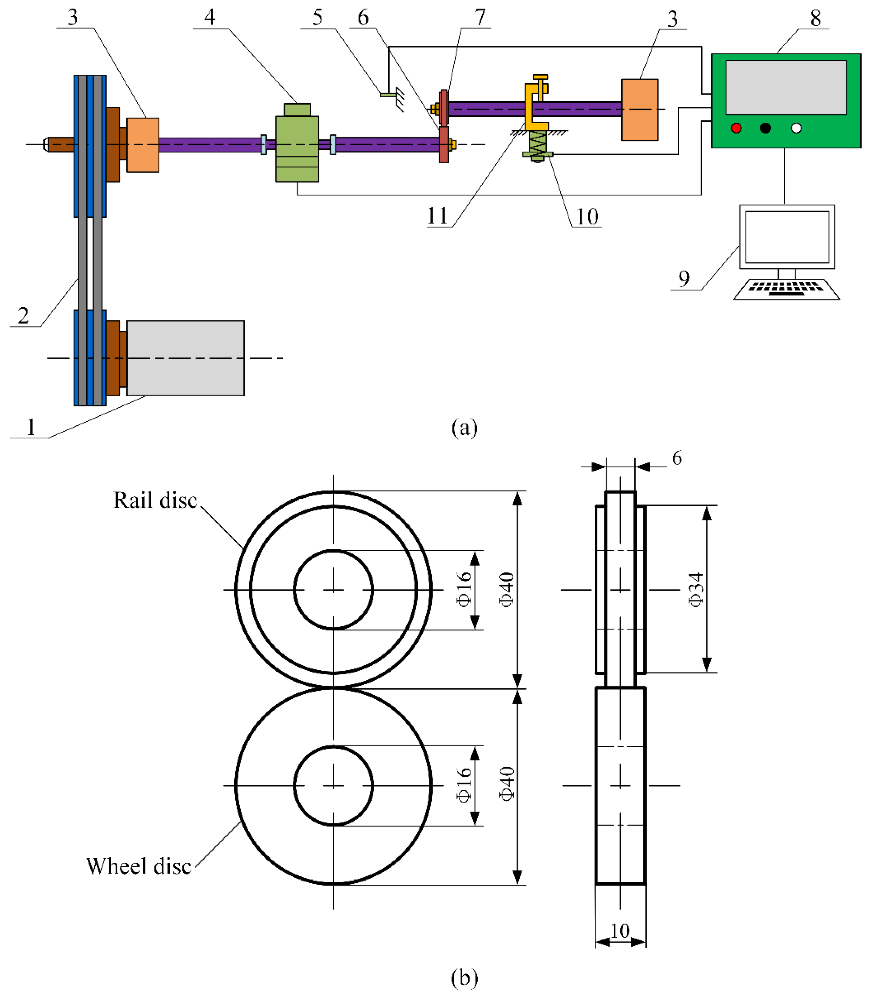
2.2. Experimental Procedures

Before the investigation of the rolling-sliding wear characteristics on the wheel/rail materials, the wheel specimens were turned by a CNC lathe and the rail specimens were ground by a cylindrical grinding machine with various machining parameters. The grinding parameters of rail discs and the turning parameters of wheel discs are shown in Table 2 and Table 3, respectively. The machining parameters of wheel/rail specimens used in this study are within the range of parameters utilized in the actual field of wheel/rail re-profiling. Figure 3 shows the photographs of the wheel/rail samples after machining. The surface roughness Ra of the machined wheel/rail discs was measured by a surface profilometer (RTEC-UP Dual Mode, USA). A Vickers hardness tester (HV-1000, China) was utilized to measure the surface hardness (HV0.1) of the machined wheel/rail discs. The averaged measurement results are displayed in Table 4. It can be found from Table 4 that the surface roughness Ra and the surface hardness HV0.1 of the machined wheel samples #W1, #W2 and #W3 present an increasing trend, meanwhile, the surface roughness Ra of the machined rail samples #R1, #R2 and #R3 shows no significant difference, and the surface hardness HV0.1 of the machined rail specimens displays a decreasing trend.
After the process of grinding, fine polishing and corroding, the cross section of every machined wheel/rail sample was utilized to carry out the micro-examination of the subsurface plastic deformation via an optical microscope (i.e., OM, DMI5000 M, Leica, Germany), as shown in Figure 4. It can be seen from Figure 4 that the thickness of plastic deformation layer of the wheel specimens is much larger than that of the rail specimens before the rolling-sliding test. Obvious plastic deformation layer of #W1, #W2 and #W3 after turning can be observed and the thickness of plastic deformation layer exhibits an increasing trend, which ranges from 14 to 25 μm. Compared with the plastic deformation layer of the wheel specimens after turning, no apparent plastic deformation layer of #R1, #R2 and #R3 after grinding can be observed, and the thickness of plastic deformation layer ranges from 2 to 4 μm.
The rolling-sliding experiments on the machined wheel/rail specimens were conducted under the dry condition via a twin-disc rolling-sliding wear testing facility, as shown in Figure 5a. This apparatus is equipped with two rollers which serve as the wheel disc (i.e., lower roller) and the rail disc (i.e., upper roller), respectively. With the transmission of the driving belt and the gearbox, the wheel disc is propelled and controlled by a DC motor, and the rail disc is then driven by the wheel disc when they make a contact with each other. The vertical loading force (ranges from 0 to 2000 N) applied on the discs is executed by the adjustment of the compression spring and its value is measured and recorded via a load transducer. The friction torque is measured by a torque transducer. The configuration and geometric size of the wheel/rail discs is displayed in Figure 5b. All of the wheel/rail discs have the outer diameter of 40 mm and the line contact width is 6 mm.
To conduct the rolling-sliding tests, the aforementioned turned wheel discs #W1, #W2 and #W3 and the ground rail discs #R1, #R2 and #R3 are matched with each other, which means that there are 9 friction pairs in total, i.e., #W1-#R1, #W2-#R1, #W3-#R1, #W1-#R2, #W2-#R2, #W3-#R2, #W1-#R3, #W2-#R3 and #W3-#R3. According to [26], the creep ratio λ between the wheel and rail discs is expressed in Equation (1). The adhesion coefficient μ can be calculated with the readings of the load sensor and the torque transducer, as formulated by Equation (2). The contact mode between the wheel/rail discs is line contact, as per [18], the maximum Hertzian contact stress is expressed in Equation (3).
λ = ω wheel R wheel ω rail R rail ω wheel R wheel = 1 ω rail R rail ω wheel R wheel
μ = 1000 T P · R rail
σ max = 0.418 P E L · R wheel + R rail R wheel R rail
where ωrail and ωwheel denote the rotational velocities of the rail and wheel specimens, respectively; Rrail and Rwheel represent the radii of the rail and wheel discs (unit: mm), respectively; T indicates the frictional torque (unit: N·m) and P is the applied normal contact force (unit: N); L represents the line contact width (unit: mm); E is the Young’s modulus (unit: MPa).
In this study, the rotational speed of the wheel disc was 400 r/min and the number of cycles was 1.92 × 10⁵. The contact stress σmax between the wheel and rail discs was set as 1000 MPa, which is in line with the typical contact pressure values under real-world wheel/rail contact [27]. The creep ratio λ between the wheel and rail discs was adopted as 10%.
All of the wheel/rail discs were carefully cleaned by virtue of ultrasonic cleaning method using ethanol for 10 minutes, and then were dried before and after each test. An electronic balance (FA1104N, China) with a measurement accuracy of 0.0001 g was engaged to weigh each sample. The surface hardness HV0.1 of the worn surfaces was measured via a Vickers hardness tester (HV-1000, China). Figure 6 displays the sampling preparation process of circumferential surface and section of the wheel/rail discs after the rolling-sliding test. The worn circumferential surfaces were characterized by a scanning electron microscope (SEM, Quanta 200, FEI, USA). Longitudinal sections were sampled along the rolling direction by EDM and each section of the sample piece was mounted into a mixture with resin powder and curing agent blended in appropriate proportion, and then was ground with abrasive papers and was finely polished by metallographic polishing agent. Finally, the cross section of the sample piece was corroded with 4% nital and was observed by means of an optical microscope (DMI5000 M, Leica, Germany).

3. Results and Discussion

3.1. Adhesion Coefficient

The changes of adhesion coefficients of the machined wheel/rail discs with the number of rolling cycles are shown in Figure 7. It can be seen from Figure 7 that the changes of the adhesion coefficient can be divided into three stages, which are running-in stage, stable wear stage and scuffing stage. At the beginning of the test, the adhesion coefficient during the running-in stage undergoes a drastic increase owing to the discrepancy of the original surface state between the friction pair, which means that the initial surface roughness of wheel/rail discs generates an instantaneous rise in friction. As the rolling-sliding process progresses (approximately 25,000 rolling cycles), the wheel/rail materials reach steady wear stage, and the adhesion coefficients between different friction pairs become stable which ranges from 0.60 to 0.66. This is caused by the fact that the surface micro-peaks are gradually worn off and the contact region between the wheel/rail interface steps into the fully sliding zone, which indicates that the adhesion force of wheel/rail reaches a state of saturation. During the stable wear stage, the adhesion coefficients among friction pairs #W3-#R1, #W3-#R2 and #W3-#R3 are great than 0.65, the adhesion coefficients among friction pairs #W2-#R1, #W2-#R2 and #W2-#R3 range from 0.61 to 0.63 and the adhesion coefficients among friction pairs #W1-#R1, #W1-#R2 and #W1-#R3 are 0.60. In the late stage of the wear test, the adhesion coefficients between varied friction pairs present a decreasing trend. This may be caused by the difference of surface damage occurring on the wheel/rail discs in the late stage of the rolling-sliding test, which brings about varied roughness between the wheel/rail contact interface.
The previous research on the wheel/rail hardness matching showed that surface hardness has little impact on the adhesion coefficient of the friction pair [28,29]. Therefore, the dominating factor influencing the adhesion coefficient is the original surface roughness of the wheel/rail discs. Due to the larger initial surface roughness of #W3 than that of #W1 and #W2, the corresponding adhesion coefficient of #W3 is larger than that of #W1 and #W2 after the rolling-sliding contact with rail discs machined with the same grinding parameters. Likewise, the corresponding adhesion coefficient of #W2 is larger than that of #W1 after the rolling-sliding contact with rail discs machined with the same grinding parameters.

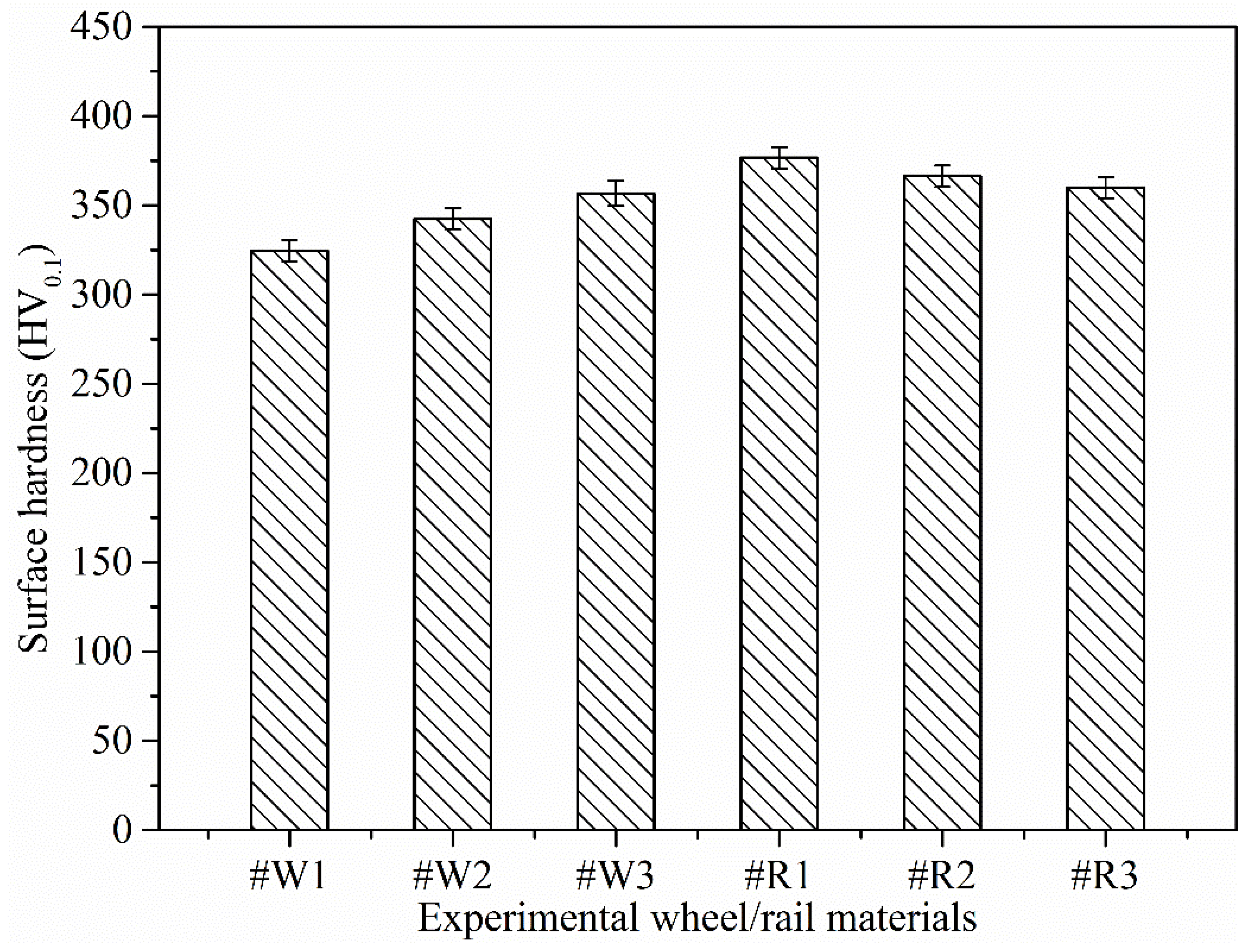
3.2. Surface Hardness and Wear Loss

The surface hardness of wheel/rail discs before the rolling-sliding contact is shown in Figure 8. Figure 9 presents the variations of surface hardness of wheel/rail discs after the rolling-sliding test. Compared with Figure 8 and Figure 9, it can be found that there is a pronounced increase in the surface hardness of wheel/rail discs after the rolling-sliding test, and that the surface hardness of the rail discs before and after the rolling-sliding test is greater than that of the wheel discs. The surface hardness of the wheel discs before the rolling-sliding test ranges from 324.48 to 356.72 HV0.1, after the rolling-sliding test, it ranges from 418.95 to 485.79 HV0.1, and the maximum increment of surface hardness of the wheel discs is 41.9%. Meanwhile, the surface hardness of the rail discs before the rolling-sliding test ranges from 359.83 to 376.56 HV0.1, after the rolling-sliding test, it ranges from 510.57 to 578.16 HV0.1, and the maximum increment of surface hardness of the rail discs is 53.5%. In general, the degree of increase in the surface hardness of the rail disc is greater than that of the wheel disc after the rolling-sliding test. The surface hardness values of #W2 and #W3 are close after the rolling-sliding contact with the rail discs machined with the same grinding parameters, which are larger than that of #W1. This means that when the machined wheel discs make the rolling-sliding contact with the rail discs machined with the same grinding parameters, the turned wheel disc with original lower surface hardness and lower surface roughness can generate relatively small surface hardness after the rolling-sliding test. Compared with the surface hardness of the rail discs, the surface hardness of #R1 is higher than that of #R2 and #R3 after the rolling-sliding contact with the wheel discs machined with the same turning parameters, which shows that when the machined rail discs make the rolling-sliding contact with the wheel discs machined with the same turning parameters, the surface hardness of the ground rail disc with initial larger surface hardness increases accordingly after the rolling-sliding test, which is beneficial to reduce the wear amount of rail material.
The cumulative wear loss of wheel/rail discs after the rolling-sliding test is shown in Figure 10. From Figure 10, it can be seen that the wear loss of the wheel disc after each rolling-sliding test is above 1.4 g, while the wear loss of the rail disc after each rolling-sliding test ranges from 0.2 to 0.3 g. The wear loss of the wheel discs is much larger than that of the rail discs, which is caused by the reason that the carbon content and the surface hardness of rail material are higher than those of wheel material. Thus, the rail material exhibits better wear-resistant performance. When #W1, #W2 and #W3 make the rolling-sliding contact with the rail discs machined with the same grinding parameters, the wear loss of #W1 and the corresponding total wear loss of wheel/rail discs are larger than those of #W2 and #W3, respectively, while the wear loss of #W2 and the corresponding total wear loss of wheel/rail discs is slightly smaller than those of #W3, which indicates that the surface roughness and hardness of the machined wheel/rail exert a combination effect on the wheel/rail anti-wear performance. Although the surface hardness of #W3 is larger than that of #W2 after the turning process, the surface roughness of #W3 is larger than that of #W2, which accelerates the wear of #W3, thus causing larger wear loss than that of #W2. When #R1, #R2 and #R3 come into the rolling-sliding contact with the wheel discs machined with the same turning parameters, the wear losses of rail material from large to small are #R3, #R2 and #R1, respectively. This is caused by the reason that due to no significant difference of surface roughness among the rail discs, the initial surface hardness of the rail discs after grinding is the dominant factor affecting the rail wear loss. From the perspective of the total wear loss of the wheel/rail discs, in all the friction pairs, #W2-#R1, #W2-#R2 and #W2-#R3 generate the relatively small amount of total wear of wheel/rail materials after the rolling-sliding test, which means that overall better abrasion resistance is reached when #W2 makes the rolling-sliding contact with the rail specimens.

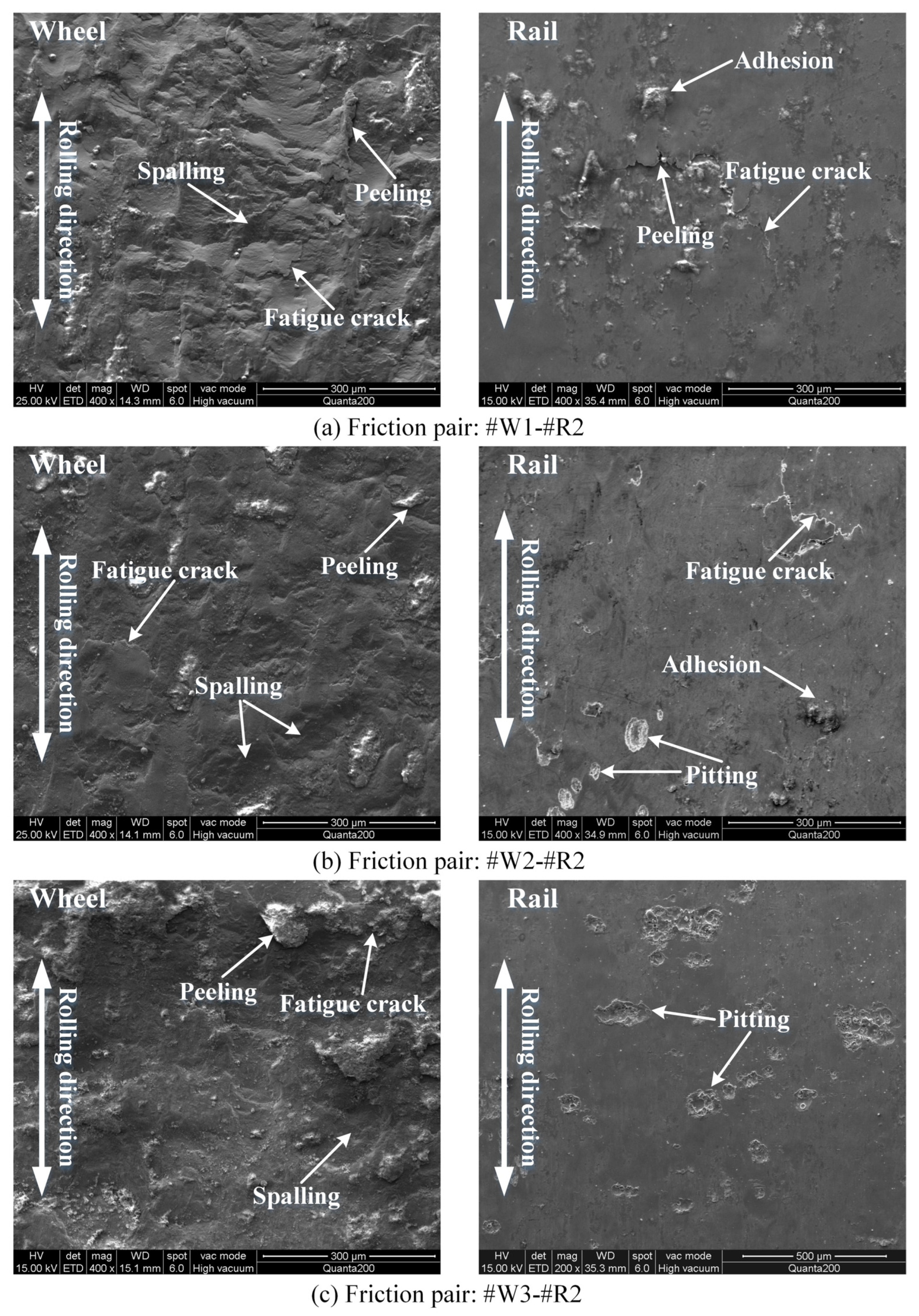
3.3. Surface Damage Characteristics

Figure 11 displays the SEM micrographs of surface damage of wheel/rail discs under friction pairs #W1-#R1, #W2-#R1 and #W3-#R1. From Figure 11a–c, it is apparent that the surface damage morphology of the wheel discs is strikingly different from that of rail discs after the rolling-sliding contact. In general, the surface damage of the wheel discs is more serious than that of the rail discs. The surface damage of the wheel discs is predominated by the combination of adhesive wear, spalling, peeling and fatigue cracks, while the surface of the rail discs presents different degrees of adhesion, pitting and fatigue cracks. Owing to the larger surface roughness of the turned wheel discs than that of the ground rail discs and the lower surface hardness of the turned wheel discs than that of the ground rail discs, adhesion of wheel material is more susceptible to occur in the wheel/rail contact interface where the shear stress is large during the rolling-sliding process, the adhesion points are sheared, transferred and smeared on the surface of the rail disc with higher surface hardness, finally causing the adhesive wear of the wheel discs. Compared with the worn surfaces of #W2 and #W3, #W1 exhibits a relatively rougher surface after the rolling-sliding test. Furthermore, the surface damage morphology of #W1 mainly exhibits deep spalling and its spalling degree is more serious than that of #W2 and #W3. More peeling and less spalling can be found on the surface of #W3, while the surface damage morphology of #W2 is mainly based on shallow spalling and the worn surface of #W2 is relatively smoother after the rolling-sliding test, which indicates that when making the rolling-sliding contact with the rail discs machined with the same grinding parameters, the surface of wheel discs with original lower surface roughness does not necessarily generate the worn surface with less damage after the rolling-sliding test. It can be also found that there is less damage on the surface of #R1 in friction pair #W1-#R1, meanwhile, slight adhesion and sparse pitting are observed on the surface of #R1 in friction pair #W2-#R1. Dense pitting is observed on the surface of #R1 in friction pair #W3-#R1.
The SEM micrographs of surface damage of wheel/rail discs under friction pairs #W1-#R2, #W2-#R2 and #W3-#R2 are presented in Figure 12. Figure 13 shows the SEM micrographs of surface damage of wheel/rail discs under friction pairs #W1-#R3, #W2-#R3 and #W3-#R3. Similarly, it is distinct that there are remarkable differences on the surface damage morphology between the wheel and rail discs. The surface damage morphology of the wheel discs in Figure 12 and Figure 13 is approximately the same as that in Figure 11. After the rolling-sliding contact with the wheel discs machined with the same turning parameters, compared with #R1 and #R2, more pitting occurs on the surface of #R3, which indicates that the surface hardness of the rail discs after grinding directly affect the surface wear morphology. Furthermore, the surface damage of #R1, #R2 and #R3 after the rolling-sliding contact with #W3 is more deteriorated than that of their rolling-sliding contact with #W1 and #W2. From the aforementioned analysis, the surface integrity of the wheel/rail discs after machining affects the formation of the surface damage morphology after the rolling-sliding contact.

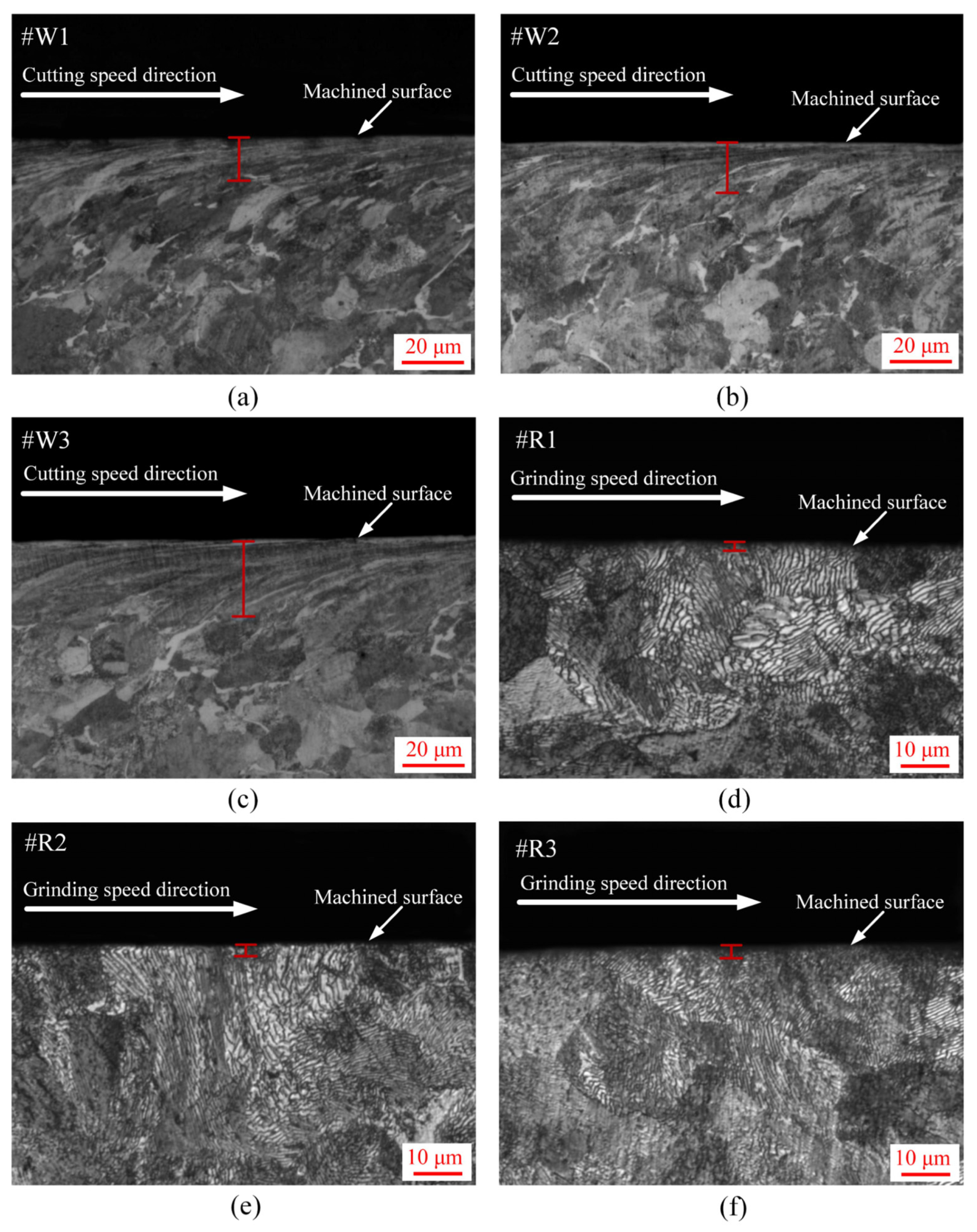
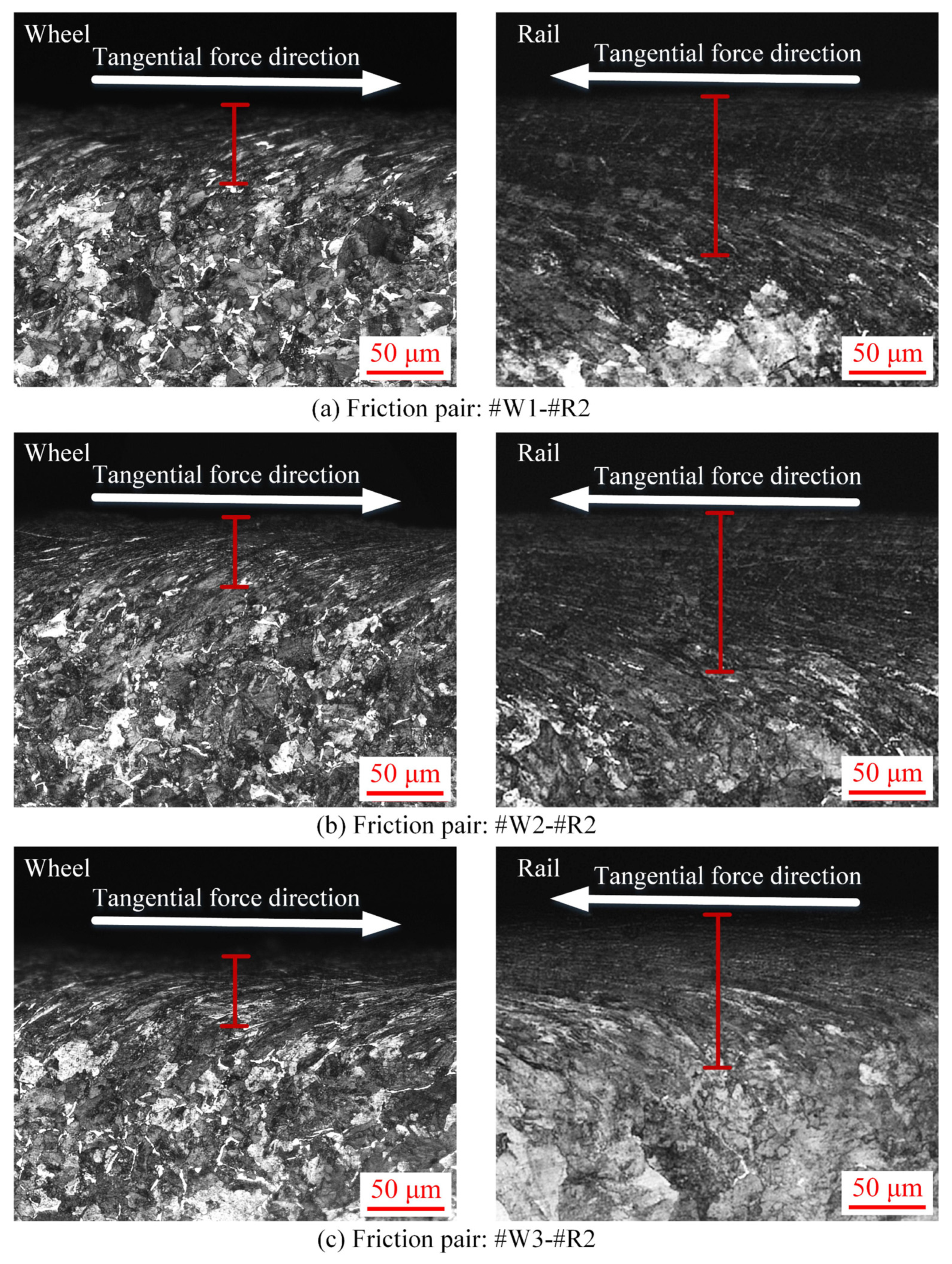
3.4. Subsurface Plastic Deformation Characteristics

Longitudinal sections of the wheel/rail discs after each rolling-sliding test were cut along the rolling direction to perform the micro-examination of the subsurface plastic deformation via an optical microscope (OM), as illustrated in Figure 6. Figure 14, Figure 15 and Figure 16 show the plastic deformation of wheel/rail specimens after the rolling-sliding test, from which it can be conspicuously observed that different degrees of plastic deformation occur on the wheel/rail materials after the rolling-sliding test. The formation of the subsurface plastic deformation layer of wheel/rail materials represents the occurrence of work hardening phenomenon during the rolling-sliding process, finally increasing the surface hardness of wheel/rail materials. According to Figure 4, the thickness of subsurface plastic deformation of the turned wheel discs is much larger than that of the ground rail discs before the rolling-sliding test, the thickness of subsurface plastic deformation of the turned wheel discs ranges from 14 to 25 μm and that of the ground rail discs ranges from 2 to 4 μm. In the meanwhile, as per the cumulative wear loss of wheel/rail discs after the rolling-sliding test shown in Figure 10, it can be concluded that the original thin layers of subsurface plastic deformation of the wheel/rail discs after machining are completely worn off during rolling-sliding process, which indicates what Figure 14, Figure 15 and Figure 16 present are the newly-formed subsurface plastic deformation layers of wheel/rail discs under the tangential force during the rolling-sliding process.
From Figure 14, Figure 15 and Figure 16, it can be observed that the microstructure of wheel/rail in the plastic deformation zone is elongated and refined along the rolling direction, which finally forms the fibrous layer. The thickness of plastic deformation layer of the wheel discs ranges from 50 to 60 μm, while the thickness of plastic deformation layer of the rail discs is greater than 85 μm. Generally speaking, the thickness of plastic deformation layer of the rail discs is larger than that of the wheel discs after the rolling-sliding contact. This is caused by the reason that the wear loss of the wheel disc is more than quadruple larger than that of the rail disc, thus the surface material of the wheel undergoing plastic deformation is quickly worn off, while the wear loss of rail material is comparatively smaller and the wear rate is slower than that of wheel material, which eventually generates a thicker layer of plastic deformation of the rail discs. After the rolling-sliding contact with the rail discs machined with the same grinding parameters, the thickness of plastic deformation layer of #W1 is larger than that of #W2 and #W3, which means that when the surface hardness and surface roughness of the wheel discs after turning are relatively low, larger plastic deformation of the wheel discs occurs after the rolling-sliding test. It can be also found that the thickness of plastic deformation layer of #W2 and #W3 is similar, indicating that when the surface hardness and surface roughness of the wheel discs after turning are increased within a certain value at the same time, the thickness of plastic deformation layer does not change significantly after the rolling-sliding contact with the rail discs. It can be seen from Figure 14 that there is no significant difference on the thickness of plastic deformation layer of #R1 after the rolling-sliding contact with #W1, #W2 and #W3. From Figure 15 and Figure 16, it can be observed that the thickness of plastic deformation layer of #R2 and #R3 is larger than that of #R1 after the rolling-sliding contact with the wheel discs machined with the same turning parameters, and the thickness of plastic deformation layer of #R3 is the largest, which means that when the surface hardness of the rail discs after grinding is large, the plastic deformation layer after the rolling-sliding contact with the wheel discs is relatively thin.

4. Conclusions

In this work, the rolling-sliding wear and damage behavior on the machined wheel/rail discs under the dry condition has been experimentally investigated via a twin-disc wear testing apparatus by changing different friction pairs. Based on the experimental results, the following conclusions can be drawn:
1. The surface hardness of the rail discs after machining is only slightly higher than that of the wheel discs, while the surface roughness and plastic deformation layer of the turned wheel discs are much larger than those of the ground rail discs. After the rolling-sliding test, the maximum increment of surface hardness of the wheel discs is 41.9%, and the maximum increment of surface hardness of the rail discs is 53.5%. The thickness of plastic deformation layer of the wheel discs after the rolling-sliding test ranges from 50 to 60 μm, while the thickness of plastic deformation layer of the rail discs is greater than 85 μm. There is a striking increase in the surface hardness of wheel/rail discs after the rolling-sliding test, the increase degree of the surface hardness of the rail discs and their thickness of plastic deformation layer are greater than those of the wheel discs.
2. The changes of adhesion coefficients of the machined wheel/rail discs with the number of rolling cycles are divided into running-in stage, stable wear stage and scuffing stage. The wheel/rail discs machined with different parameters generate varied adhesion coefficients during the rolling-sliding process, and the wheel discs with larger surface roughness engender higher adhesion coefficients. The adhesion coefficients between different friction pairs become stable ranging from 0.60 to 0.66 during the steady wear stage.
3. The surface damage morphology of the wheel discs is strikingly different from that of rail discs after the rolling-sliding contact. In general, the surface damage of the wheel discs is more serious than that of the rail discs. The surface damage of the wheel discs is predominated by the combination of adhesive wear, spalling, peeling and fatigue cracks, while the main surface damage of rail discs presents obvious pitting and fatigue cracks.
4. After each rolling-sliding test, the wear loss of the wheel disc is above 1.4 g, while the wear loss of the rail disc ranges from 0.2 to 0.3 g. The wear loss of the wheel discs is much larger than that of the rail discs, and the rail material displays better wear-resistant performance. The surface hardness, surface roughness and plastic deformation layer of the wheel/rail discs after machining exert a comprehensive effect on the wear behavior, and friction pair with appropriate original surface hardness and roughness generates the smallest amount of wear loss. From the perspective of the total wear loss of wheel/rail discs, overall better abrasion resistance is reached when #W2 makes the rolling-sliding contact with the rail discs.

Author Contributions

Conceptualization, P.L. and Y.Q.; methodology, P.L.; software, P.L.; validation, P.L., J.W. and L.Y.; formal analysis, P.L.; investigation, P.L., J.W. and L.Y.; resources, Y.Q.; data curation, P.L. and L.Y.; writing—original draft preparation, P.L.; writing—review and editing, P.L. and Y.Q.; visualization, P.L., J.W. and L.Y.; supervision, Y.Q.; project administration, Y.Q.; funding acquisition, Y.Q. All authors have read and agreed to the published version of the manuscript.

Funding

This research was funded by the National Natural Science Foundation of China, grant number 51675184; the Science and Technology Planning Project of Guangdong Province, grant number 2016A010102006.

Acknowledgments

The authors gratefully acknowledge the National Natural Science Foundation of China (Grant No. 51675184) and the Science and Technology Planning Project of Guangdong Province (Grant No. 2016A010102006).

Conflicts of Interest

The authors declare no conflicts of interest.

References

  1. Daves, W.; Kráčalík, M.; Scheriau, S. Analysis of crack growth under rolling-sliding contact. Int. J. Fatigue 2019, 121, 63–72. [Google Scholar] [CrossRef]
  2. Grassie, S.L. Rail corrugation: Characteristics, causes, and treatments. Proc. Inst. Mech. Eng. Part F-J. Rail Rapid Transit. 2009, 223, 581–596. [Google Scholar] [CrossRef]
  3. Zeng, D.; Lu, L.; Gong, Y.; Zhang, Y.; Zhang, J. Influence of solid solution strengthening on spalling behavior of railway wheel steel. Wear 2017, 372–373, 158–168. [Google Scholar] [CrossRef]
  4. Kaewunruen, S.; Ishida, M.; Marich, S. Dynamic wheel-rail interaction over rail squat defects. Acoust. Aust. 2015, 43, 97–107. [Google Scholar] [CrossRef]
  5. Singleton, R.; Marshall, M.B.; Lewis, R.; Evans, G. Rail grinding for the 21st century-taking a lead from the aerospace industry. Proc. Inst. Mech. Eng. Part F-J. Rail Rapid Transit. 2014, 229, 457–465. [Google Scholar] [CrossRef] [Green Version]
  6. Uhlmann, E.; Lypovka, P.; Hochschild, L.; Schröer, N. Influence of rail grinding process parameters on rail surface roughness and surface layer hardness. Wear 2016, 366–367, 287–293. [Google Scholar] [CrossRef]
  7. Wang, J.; Xue, X.; Lu, Y. Study on cutting form and surface machining quality of wheel tread under reprofiling. Adv. Mater. Sci. Eng. 2017, 2017, 6950351. [Google Scholar] [CrossRef] [Green Version]
  8. Wang, L.; Xu, H.; Yuan, H.; Zhao, W.; Chen, X. Optimizing the re-profiling strategy of metro wheels based on a data-driven wear model. Eur. J. Oper. Res. 2015, 242, 975–986. [Google Scholar] [CrossRef]
  9. Lai, Q.; Abrahams, R.; Yan, W.; Qiu, C.; Mutton, P.; Paradowska, A.; Soodi, M. Investigation of a novel functionally graded material for the repair of premium hypereutectoid rails using laser cladding technology. Compos. Part B-Eng. 2017, 130, 174–191. [Google Scholar] [CrossRef]
  10. Lai, Q.; Abrahams, R.; Yan, W.; Qiu, C.; Mutton, P.; Paradowska, A.; Fang, X.; Soodi, M.; Wu, X. Effects of preheating and carbon dilution on material characteristics of laser-cladded hypereutectoid rail steels. Mater. Sci. Eng. A Struct. Mater. 2018, 712, 548–563. [Google Scholar] [CrossRef]
  11. Zeng, D.; Lu, L.; Li, Z.; Zhang, J.; Jin, X.; Zhu, M. Influence of laser dispersed treatment on rolling contact wear and fatigue behavior of railway wheel steel. Mater. Des. 2014, 54, 137–143. [Google Scholar] [CrossRef] [Green Version]
  12. Lewis, S.R.; Lewis, R.; Fletcher, D.I. Assessment of laser cladding as an option for repairing/enhancing rails. Wear 2015, 330–331, 581–591. [Google Scholar] [CrossRef]
  13. Roy, T.; Abrahams, R.; Paradowska, A.; Lai, Q.; Mutton, P.; Soodi, M.; Fasihi, P.; Yan, W. Evaluation of the mechanical properties of laser cladded hypereutectoid steel rails. Wear 2019, 432–433, 202930. [Google Scholar] [CrossRef]
  14. Lai, Q.; Abrahams, R.; Yan, W.; Qiu, C.; Mutton, P.; Paradowska, A.; Soodi, M.; Wu, X. Influences of depositing materials, processing parameters and heating conditions on material characteristics of laser-cladded hypereutectoid rails. J. Mater. Process. Technol. 2019, 263, 1–20. [Google Scholar] [CrossRef]
  15. Roy, T.; Lai, Q.; Abrahams, R.; Mutton, P.; Paradowska, A.; Soodi, M.; Yan, W. Effect of deposition material and heat treatment on wear and rolling contact fatigue of laser cladded rails. Wear 2018, 412–413, 69–81. [Google Scholar] [CrossRef]
  16. Razhkovskiy, A.A.; Bunkova, T.G.; Petrakova, A.G.; Gateluk, O.V. Optimization of hardness ratio in rail-wheel friction pair. J. Frict. Wear 2015, 36, 334–341. [Google Scholar] [CrossRef]
  17. Shi, X.; Yan, Q.; Zhang, X.; Diao, G.; Zhang, C.; Hong, Z.; Wen, Z.; Jin, X. Hardness matching of rail/wheel steels for high-speed-train based on wear rate and rolling contact fatigue performance. Mater. Res. Express 2019, 6, 066501. [Google Scholar] [CrossRef]
  18. Seo, J.W.; Jun, H.K.; Kwon, S.J.; Lee, D.H. Rolling contact fatigue and wear of two different rail steels under rolling-sliding contact. Int. J. Fatigue 2016, 83, 184–194. [Google Scholar] [CrossRef]
  19. Ma, L.; He, C.G.; Zhao, X.J.; Guo, J.; Zhu, Y.; Wang, W.J.; Liu, Q.Y.; Jin, X.S. Study on wear and rolling contact fatigue behaviors of wheel/rail materials under different slip ratio conditions. Wear 2016, 366–367, 13–26. [Google Scholar] [CrossRef]
  20. Roy, T.; Paradowska, A.; Abrahams, R.; Law, M.; Mutton, P.; Soodi, M.; Yan, W. Residual stress in laser cladded heavy-haul rails investigated by neutron diffraction. J. Mater. Process. Technol. 2020, 278, 116511. [Google Scholar] [CrossRef]
  21. Lyu, Y.; Bergseth, E.; Olofsson, U.; Lindgren, A.; Höjer, M. On the relationships among wheel-rail surface topography, interface noise and tribological transitions. Wear 2015, 338–339, 36–46. [Google Scholar] [CrossRef]
  22. Hardy, A.E.J.; Jones, R.R.K.; Turner, S. The influence of real-world rail head roughness on railway noise prediction. J. Sound Vibr. 2006, 293, 965–974. [Google Scholar] [CrossRef]
  23. Li, Q.; Thompson, D.J.; Toward, M.G.R. Estimation of track parameters and wheel-rail combined roughness from rail vibration. Proc. Inst. Mech. Eng. Part F-J. Rail Rapid Transit. 2017, 232, 1149–1167. [Google Scholar] [CrossRef] [Green Version]
  24. Liu, P.J.; Quan, Y.M.; Ding, G. Dynamic mechanical characteristics and constitutive modeling of rail steel over a wide range of temperatures and strain rates. Adv. Mater. Sci. Eng. 2019, 2019, 6862391. [Google Scholar] [CrossRef] [Green Version]
  25. Solid Forged and Rolled Wheels for Railway Wagon Applications, Railway Industry Standards of the People’s Republic of China; TB/T 2817-2018; China Railway Publishing House: Beijing, China, 2018.
  26. Wang, W.J.; Wang, H.; Wang, H.Y.; Guo, J.; Liu, Q.Y.; Zhu, M.H.; Jin, X.S. Sub-scale simulation and measurement of railroad wheel/rail adhesion under dry and wet conditions. Wear 2013, 302, 1461–1467. [Google Scholar] [CrossRef]
  27. Ramalho, A. Wear modelling in rail-wheel contact. Wear 2015, 330–331, 524–532. [Google Scholar] [CrossRef]
  28. Wang, W.J.; Liu, Q.Y.; Zhu, M.H. Hardness matching behavior of wheel rail materials. Tribology 2013, 33, 65–69. (In Chinese) [Google Scholar]
  29. Su, P.; Wang, A.B.; Jv, L.H.; Gao, X.G. Analysis of wheel/rail noise development mechanism based on the hardness test of wheel and rail materials. Noise Vibr. Control 2018, 38, 209–212. (In Chinese) [Google Scholar]
Figure 1. Sampling positions of the wheel/rail specimens.
Metals 10 00472 g001
Figure 2. SEM micrographs of wheel/rail specimens: (a) wheel steel; (b) rail steel.
Metals 10 00472 g002
Figure 3. Photographs of the wheel/rail samples after machining: (a) wheel samples after turning; (b) rail samples after grinding.
Metals 10 00472 g003
Figure 4. Optical microscope (OM) micrographs of subsurface plastic deformation of wheel/rail samples after machining: (a) #W1; (b) #W2; (c) #W3; (d) #R1; (e) #R2; (f) #R3.
Metals 10 00472 g004
Figure 5. Experimental setup for the rolling-sliding tests. (a) Schematic illustration of the testing apparatus. 1, DC motor; 2, driving belt; 3, gearbox; 4, torque transducer; 5, rotational speed transducer; 6, lower roller; 7, upper roller; 8, controller; 9, computer; 10, load transducer; 11, compression spring. (b) Configuration and geometric size of the wheel/rail discs (unit: mm).
Metals 10 00472 g005
Figure 6. Sampling preparation of circumferential surface and section of the wheel/rail discs after the rolling-sliding test.
Metals 10 00472 g006
Figure 7. Variations of adhesion coefficients with the number of rolling cycles between different wheel/rail friction pairs.
Metals 10 00472 g007
Figure 8. Surface hardness of the wheel/rail discs before the rolling-sliding contact.
Metals 10 00472 g008
Figure 9. Variations of surface hardness of the wheel/rail discs after the rolling-sliding contact.
Metals 10 00472 g009
Figure 10. Cumulative wear loss of the wheel/rail discs after the rolling-sliding contact.
Metals 10 00472 g010
Figure 11. SEM micrographs of surface damage of the wheel/rail discs under different friction pairs: (a) #W1-#R1; (b) #W2-#R1; (c) #W3-#R1.
Metals 10 00472 g011
Figure 12. SEM micrographs of surface damage of the wheel/rail discs under different friction pairs: (a) #W1-#R2; (b) #W2-#R2; (c) #W3-#R2.
Metals 10 00472 g012
Figure 13. SEM micrographs of surface damage of the wheel/rail discs under different friction pairs: (a) #W1-#R3; (b) #W2-#R3; (c) #W3-#R3.
Metals 10 00472 g013
Figure 14. OM micrographs of subsurface plastic deformation of the wheel/rail discs under different friction pairs: (a) #W1-#R1; (b) #W2-#R1; (c) #W3-#R1.
Metals 10 00472 g014
Figure 15. OM micrographs of subsurface plastic deformation of the wheel/rail discs under different friction pairs: (a) #W1-#R2; (b) #W2-#R2; (c) #W3-#R2.
Metals 10 00472 g015
Figure 16. OM micrographs of subsurface plastic deformation of the wheel/rail discs under different friction pairs: (a) #W1-#R3; (b) #W2-#R3; (c) #W3-#R3.
Metals 10 00472 g016
Table 1. Chemical constituents of rail and wheel materials (wt.%).
MaterialsCMnSiSPFe
Rail0.65–0.760.70–1.200.15–0.58≤0.025≤0.030Balance
Wheel0.55–0.650.50–0.800.17–0.37≤0.025≤0.025Balance
Table 2. Grinding parameters of the rail specimens.
Experiment NumberGrinding Wheel Velocity Vs (m/s)Workpiece Velocity Vw (m/s)Depth of Cut ap (mm)
#R1300.50.02
#R2300.80.05
#R3301.10.08
Table 3. Turning parameters of the wheel specimens.
Experiment NumberCutting Speed Vc (m/min)Feed f (mm/r)Depth of Cut ap (mm)
#W1700.41.2
#W2700.61.4
#W3700.81.6
Table 4. Surface roughness and hardness of the machined wheel/rail discs.
Experiment NumberSurface Roughness Ra (μm)Surface Hardness (HV0.1)
#W13.02324.48
#W24.18342.35
#W36.41356.72
#R11.32376.56
#R21.45366.37
#R31.38359.83

