Article

Application of the Progressive Forming Method in Simulation and Experimental Study of Rectangular Fins in a Heat Exchanger

School of mechanical engineering, Kyungnam University, 7 Kyungnamdaehak-ro, Masanhappo-gu, Changwon-si, Gyeongsangnam-do 51767, Korea
Metals 2020, 10(3), 395; https://doi.org/10.3390/met10030395
Submission received: 6 March 2020 / Accepted: 16 March 2020 / Published: 19 March 2020
(This article belongs to the Special Issue Application of FEM-Simulation in Metal Forming)

Abstract

:
A progressive forming method is applied where stamping is continuously executed to produce the rectangular fins of the plate fin heat exchanger. This process produced the fins one-by-one instead of by bundles. In order to produce a fin having a depth of more than 6.0 mm, the forming load and effective stress according to the size of the edge radii of punch and die are predicted by forming simulation. Furthermore, the process of forming the second, as well as the third, fins is predicted. As the edge radii of the die and those of the punch became smaller, the effective stresses generated during deformation became smaller. The forming load during deformation also became smaller. The sizes of the edge radii of die and punch were set to 0.5 mm and 0.2 mm, respectively. When the second fin was formed, overforming occurred at the ribs. The punch was therefore modified so that the rib could be compressed at the same time the fin was formed. With the designed process, the inner fins close to the target size could be manufactured. The resulting fins had right-angled ribs, although the fin width was a slightly opened isosceles trapezoid due to the spring-back.

1. Introduction

Plate fin heat exchangers are devices that conduct heat transfer as fluids of different temperatures pass between a finned chamber and a plate. The key component in the plate fin heat exchangers, which are used in automobile parts including radiators, intercoolers, and air conditioner condensers are over 100 assembled inner fins [1,2]. Recently, as the demand for comfort and fuel efficiency improvement for cars have been increasing, compact, lightweight, and high-performance aspects of heat exchangers have been demanded [3,4,5]. Lightweight and high-quality plate fin heat exchangers are directly related to the shape and materials of inner fins, and the shape and materials of inner fins are closely related to manufacturing technology [6,7].
The inner fin of the plate fin heat exchanger is a product in which corrugated fins are arranged in a uniform pattern on the thin plate. Since heat exchange takes place while the fluid passes through the inner fins, it is essential for them to possess the same shape with a constant gap. Fins should be narrow and deep in order to improve thermal efficiency. In addition, they should have mechanical strength, to some extent, in order to withstand the pressure difference of the fluids. Specifically, the manufacturing cost of the inner fins should be low and the production mode should be in mass quantity because about 100 inner fins are assembled on the plate fin heat exchangers. The manufacturing process that meets such requirements of the inner fin is a stamping process [8,9,10]. Jin et al. [11] used the commercial Finite Element Method (FEM) to analyze the optimization of plate type heat exchanger. Choi et al. [12] fabricated corrugated plate for a plate-type heat exchanger using multi-step stamping for improved formability.
The stamping process can form numerous fins in one process. In addition, its production cost is low and it can be manufactured in large quantities. However, there can be cracks, tears, or wrinkles in the corrugated plates during the manufacturing of fins. If the plate is thin, severe warpage can occur. Furthermore, since spring-back occurs during processing, there is a problem of forming a fin shape with a right angle. This problem can be resolved by using progressive forming. With progressive forming, several numbers of fins are not formed at once, but are formed one by one. If a ductile plate is used for forming, a fin with enough depth can be formed. However, high-speed forming should be executed to increase productivity [13,14,15,16].
In this study, progressive forming was adopted in order to produce inner fins with a depth of more than 6 mm. Because the inner fins should be formed continuously with high speed, a process in the order of uncoiler, feeder, and stamping die was planned in this study. The forming load and effective stress according to the die shape (edge radius) were predicted by means of a forming simulation with the help of a commercial program, while the die shape was selected from the simulation results. The deformation and defect were also analyzed while the inner fins were formed. The die shape was modified to avoid the defects derived from the simulation results. The modified die shape was adopted in the actual experiment, and the final inner fin samples were prepared.

2. Method of Experiment and Simulation

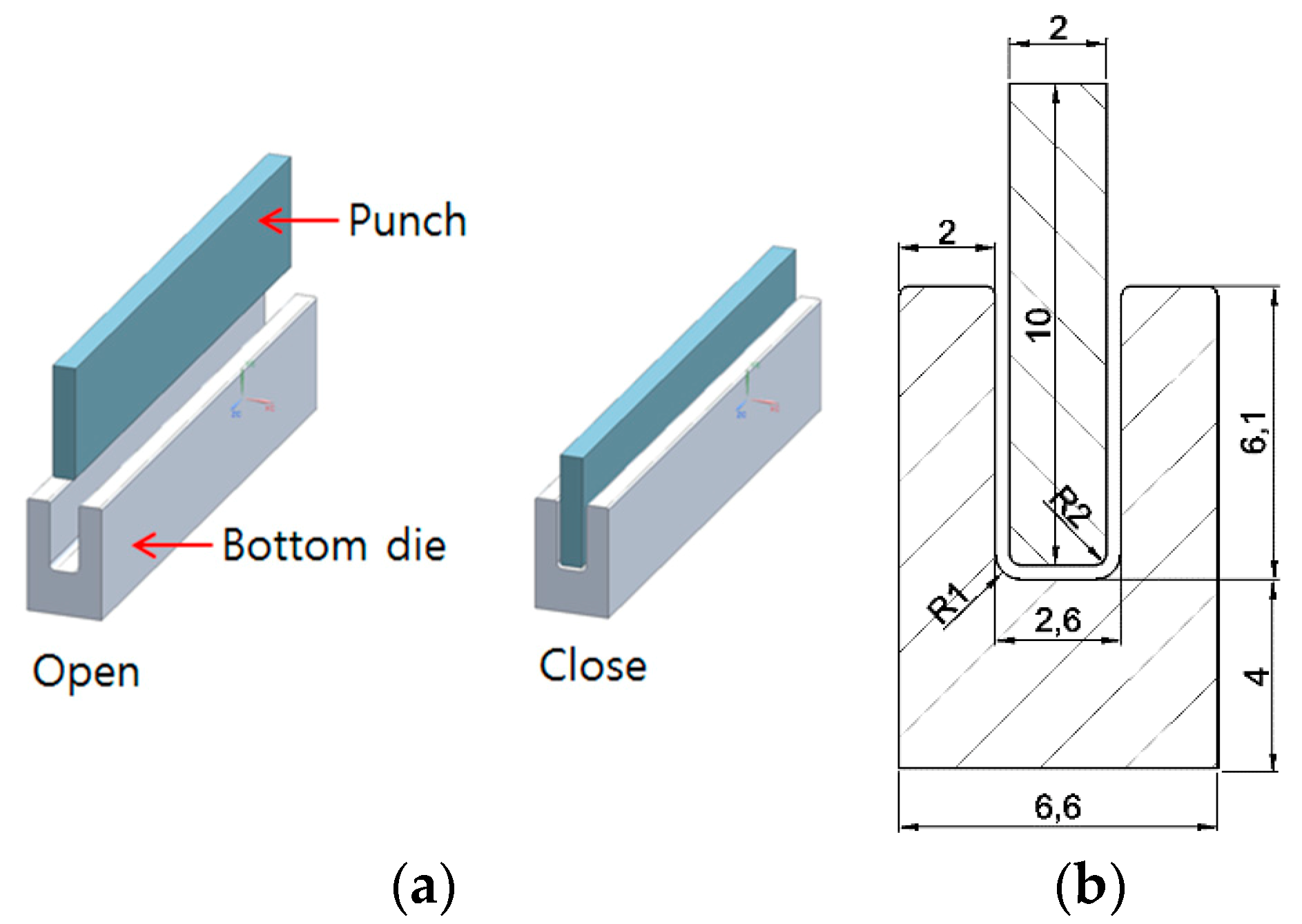
2.1. Design of Inner Fins

A cross section of the inner fin shows a uniformly formed corrugation exhibiting a constant gap. In order to raise heat transfer efficiency, the fins should be deep and the number of fins at a specific length should be large. To increase the number of fins, the fin shape should have a right angle and be narrow. Based on these requirements, the fin shape was designed to be rectangular as in Figure 1, which illustrates the inner fins of the plate fin heat exchanger. The length of the inner fin was 100 mm, and its depth was 6.1 mm. The width of the fin was 2.0 mm and each fin had a right angle. The thickness of the inner fin was set to 0.3 mm, the same thickness as the plate used to produce the fins. Outer edge radius (R1) and inner edge radius (R2) were decided from the set values for the simulation conditions.
Figure 2 shows the die and punch shape that performs the forming simulation of the inner fins. The die consists of a punch with “l” shape and a lower die with “U” shape. The lower die was fixed, and the punch was a moving type of up and down motion. The mode of forming is that while punch was descended, the blank was pushed into the lower die. The clearance, which is a gap between the punch and die, was set to 0.

2.2. Material of Inner Fins

Pure aluminum series A11060 was used as the material for inner fin. The coil-type A11060 plate having a thickness of 0.3 mm was used in this study. The mechanical properties of A11060 plate were investigated before they were input to the engineering data of the simulation program. Therefore, the tensile test and micro Vickers hardness (HM-210, Mitutoyo, Kawasaki, Japan) experiments were conducted. Tensile test specimens were processed towards three directions, along the rolling direction (0°), perpendicular to the rolling direction (90°), and 45 degrees to the rolling direction (45°). The specimens were prepared in accordance with ASTM E8/E8M-09 rectangular tension test specimen. The gage length was 50 mm and the gage width was 12.5 mm. The speed of the cross head of tensile tester was set to 5 mm/min, with the initial strain rate of 1.66 × 10⁻³ s−1. The micro Vickers hardness test was carried out towards the cross-sectional area of the sheet.
Table 1 shows the mechanical properties of the material A11060 obtained from the tensile test and micro Vickers hardness test. The yield strength was in the range of 21.2–29.2 MPa, the tensile strength 95.5–98.3 MPa, and the elongation rate 22.5–25.0%. Work hardening exponent refers to a slope of the flow stress curve. If a work hardening exponent was lower than 0.17 in the plate forming process, it would be considered as a material with poor formability. Meanwhile, if it was about 0.2, the material would be considered as having excellent formability [17]. The work hardening exponents for the directions of 0°, 45°, and 90° of the specimen A11060 were 0.215, 0.210, and 0.212, respectively, whereas the Vickers hardness value of the material was 45 HV.

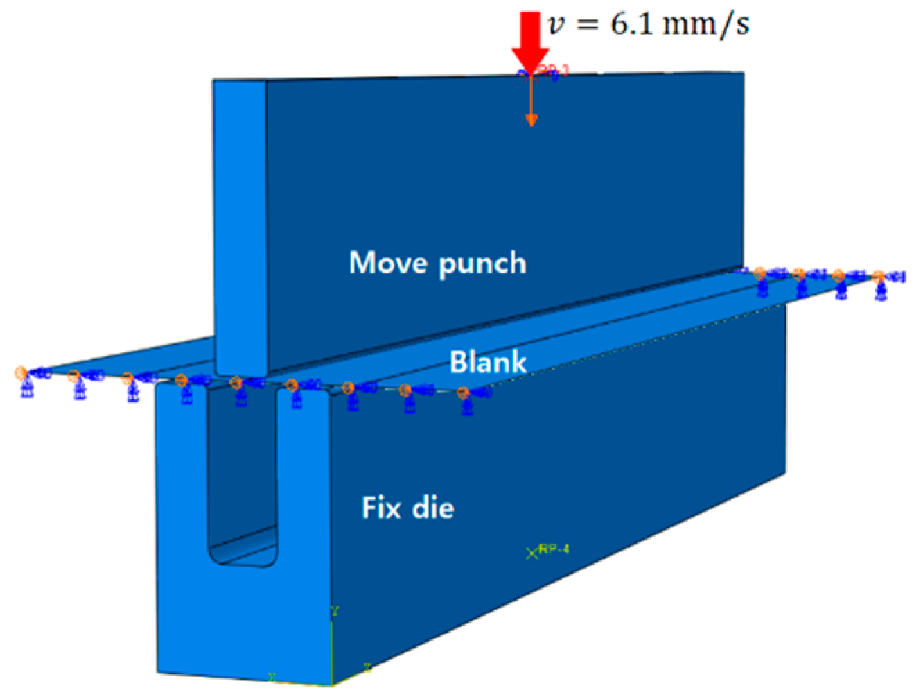
2.3. Simulation Method

The forming simulation by stamping the single fin with the punch and lower die was conducted via ABAQUS simulation program. This program provides an isotropic elasto-plasticity hardening model that is useful for cases involving gross plastic straining. Although this model is referred to as a hardening model, strain softening or hardening followed by softening can be defined. This material model is either as a rate-dependent or as a rate-independent model [18]. In this formulation, the strain rate decomposition is d ε ˙ = d ε ˙ el + d ε ˙ pl . d ε ˙ el is elastic component of the strain-rate tensor and d ε ˙ pl is plastic component of the strain-rate. The general flow rule e pl = d e - pl n . Where the flow direction n = 3 2 S q and the Mises equivalent stress q = 3 2 S : S , and d e - pl is the (scalar) equivalent plastic strain rate [18]. Von Mises yield criterion is:
3 G ( e ¯ Δ e ¯ p l ) σ ¯ = 0
This is a nonlinear equation for Δ e ¯ pl in the general case when σ ¯ depends on the equivalent plastic strain. Where G is shear modulus and σ ¯ is uniaxial strength. e ˜ is written as e ˜ = 2 3 e ^ : e ^ , e ^ = e el | t + Δ e and the deviatoric strain e = ε 1 3 ε vol I [18].
Equation (1) is solved by Newton’s method as follows:
c p l = 3 G ( e ˜ Δ e ¯ p l ) σ ¯ 3 G + H
where isotropic hardening of modulus H = d   σ ¯ d   e ¯ pl and Δ e ¯ pl = Δ e ¯ pl + c pl . The process is iterated until a convergence is reached. An overview of the ABAQUS theory manual and all kinds of information can be found elsewhere [18].
After the modeling of the punch, die, and blank with a 3D modeling program, each modeling file was loaded on the simulation program. The mechanical properties of the material A11060 in Table 1 were input in the engineering data of the simulation program. In order to perform the Finite Elements Method, mesh should be formed for the die and blank for Finite Elements Method. To derive accurate simulation results without incurring an extended analysis time, the mesh of the data that affected the simulation results should be set as fine as possible, while the portion which did not affect the result should be set rough. Figure 3 shows the setting of the mesh for the punch, die, and blank. For the blank, the mesh was divided into four partitions in the width direction first, with the sizes of meshes rendered different in each partition. In the center where forming was concentrated, the mesh size was set fine, whereas the mesh sizes at the edges (partition 1 and partition 4) were set rough. For the die, the mesh was set fine at the curved edges, while the mesh was set rough at the rest of the straight parts.
Once the mesh was set, boundary conditions were set next. Figure 4 shows boundary conditions defined for the die and the punch. The boundary conditions were applied in the same way as the actual manufacturing condition of the inner fins. The lower die was completely fixed on the press bed (6 degree of freedom fixed) and the punch was set to descend only. The punch speed was set to 6.1 mm/s to move down, that is, the forming speed to make the blank U shape was 1 s. The blank in Figure 4 had both ends free, but in practical cases, the left end was connected to the uncoiler, therefore, a symmetry condition was given in order to assume the blank as a continuum. Between the die and the blank, frictionless condition was assumed.
Table 2 shows the variables of simulation for the curved edge radius sizes of the punch and die. R1 refers to the curved edge radius of the lower die, while R2 refers to the curved edge radius of the punch in this study. Since the thickness of the blank was 0.3 mm, there was a size difference of 0.3 mm between R1 and R2. Four types of variables were set to analyze the effective stress and load according to R1 and R2 during deformation. In case of plate forming, both the elasticity and plastic deformation behavior should be considered. Therefore, the simulation was conducted with the implicit-quasi static with which linear analysis and non-linear analysis both could be carried out.

2.4. Experimental Method

The process for continuous inner fin production with a progressive forming is schematically shown in Figure 5. The forming device consists of an uncoiler, a feeder, and a set of punch and die. The A11060 plate in a coil form was hung on the uncoiler and the plate was inserted into the feeder. The plate after passing the feeder entered between the punch and die installed in the press. One side of the plate was fixed at the feeder, and other faces of the plate are free. Since one face of the plate material was locked to the feeder, it would not be moved out from the die when the punch compressed the plate. When the punch descended and the plate was pushed into the die cavity, one fin was formed. As the punch ascended, the feeder would push the plate in-between the punch and die precisely as much as fin pitch (4.6 mm). At the same time, die 3 moved downwards. While this process cycle was repeated, inner fins were produced. The speed of the punch to move up and down was 6.1 mm/s each and the speed for the feeder to transfer the plate was 4.6 mm/s. Therefore, the time taken to form one fin was 3 s. The punch was controlled as a stroke mode and was moved down as much as the set distance. Further, the force required to form a fin by the punch was measured through a load cell.

3. Results of Experiment and Simulation

3.1. Simulation

3.1.1. First Forming

Figure 6 shows the simulation results in terms of effective stress distribution for the single fin forming by the stamping process of the punch and die. The images at the left side of Figure 6 show the punch, die, and blank. The image at the right side in Figure 6 shows the simulation results only for the blank. The first stage of stamping is shown in Figure 6a where the blank start was pushed to the entrance of the die cavity by the punch and was deformed into a V shape. During this process, the stress over the yield strength of the A11060 material was generated at the bending zone and the material underwent a complete plastic deformation. Figure 6b shows the second stage of stamping wherein the punch entered the die cavity and the V angle of the blank became narrower. Since a bending occurred at large, the effective stress around more than 50 MPa was generated at the bending zone. Figure 6c shows the third stage of forming in which the punch was pushed into the die cavity, the V shape of the material was deformed to a U shape. In this stage, it was not the bottom face of the punch that pushed the blank down but the left and right faces of the punch. Therefore, the stress at the bending zone was less than that in the previous stage and the stresses were generated from the left, as well as the right faces close to the bending zone, which was about 40 MPa. Figure 6d shows the last stage of forming where the punch and blank touched the die cavity and fin was formed to a final shape. In this stage, since the blank was compressed while the bottom of the punch contacted the bottom face of the die cavity, the highest effective stress value of 69 MPa was generated at the bending zone.
Figure 7 shows the differences of effective stresses during the forming stages according to the R1 of the die and R2 of the punch. Figure 7a shows the second stage of Figure 6b. Condition 1 (R1= 1.0 mm and R2= 0.7 mm) and Condition 2 (R1= 0.7 mm and R2= 0.4 mm) generated the effective stress of more than 60 MPa in the bending zone. Under Condition 2, the area where the effective stress of more than 60 MPa was generated was smaller than that under Condition 1. With Condition 3 (R1= 0.5 mm and R2= 0.2 mm), an effective stress of about 55 MPa was generated in the bending zone, that is, the smaller the R1 and R2 were, the smaller the effective stress was. Figure 7b shows the third stage of Figure 6c. The effective stress in the bending zone of the U shape was 65 MPa under Condition 1, and most of the effective stresses were 40 MPa under Condition 2 except in some areas having an effective stress of 60 MPa. Under Condition 3, the effective stress values were about 40 MPa in all the zones. It was also found that as R1 and R2 became smaller, the effective stresses also became smaller in the bending zone of U shape. Figure 7c shows the last stage of Figure 6d. In this stage, the results were different from those found in the earlier stages. The area where the effective stress was the largest (Condition 3) was the largest, and the area of effective stress was the smallest under Condition 1. As the R1 and R2 were smaller, the area where the punch and die contacted became larger. In the last stage of forming, pressure was imposed while the blank contacted the bottom of the punch and bottom of the die cavity. Therefore, even if the effective stress equivalent to the ultimate tensile strength on the blank was generated, a crack would not occur. The stages where a crack could occur the most were the first and the second stages of forming. In this stage, since straight blank was deformed to a V shape, there was a high risk of a crack when the effective strength reached the ultimate tensile strength.
Figure 8 shows the forming load during the forming process of single fin calculated with the simulation program. The required load according to the R1 of the die and R2 of the punch was expressed over time. It is obvious that the largest load was required in the first stage (the process of deforming the blank to V shape). From the moment the blank entered the die cavity, the forming load decreased. When the blank was inserted about halfway into the die cavity, the forming load for deformation was almost zero, that is, a plastic deformation was completed when the blank entered the entrance of the die cavity and only the punch pushed the blank down from the next stage. The forming load according to the R1 of the die and R2 of the punch was the highest in Condition 1, while it was the smallest in Condition 3. In the first stage, the load 163 N was consumed under Condition 1, 149 N was consumed under Condition 2, and it was 70 N under Condition 3. Condition 3 needed about half of the load of Condition 1. Considering the effective stress and forming load in the process of deforming blank into fin, Condition 3 (R1= 0.5 mm and R2= 0.2 mm) would be the most suitable for fin processing.

3.1.2. Second Forming

Figure 9 shows the simulation results of forming in the second fin after forming in the first fin. When the punch pushed the blank into the die cavity, the blank was deformed to a V shape, which is why the rib was not deformed to a right angle during the forming process but was deformed to a round shape. The ideal shape of the fin should have a right angle with the ribs at the top and bottom, similar with the right angles shown in Figure 1.
Therefore, the shape of the punch was modified to form the rib with a right angle as in Figure 10a. The rib was designed in such a way that the rib could be compressed at the same time the fin was formed by the punch. As confirmed from the simulation results in Figure 10b, the rib portion was formed with a right angle.

3.2. Experiment

The inner fin sample produced with the punch and die is shown in Figure 2 and that produced by the punch and die in Figure 10a are presented in Figure 11. There were no visible cracks and wrinkles, as well as large warpage in both the samples. The cross-sectional observation and size measurement of the fin were carried out by means of a digital microscope (100× magnification of compact lens).
Figure 12a shows the cross-sectional shape of the fin produced by the punch and the die in Figure 2. The rib was round and not right-angled, similar to the results in Figure 9. The rib was formed with a bigger bulge compared with the simulation result. Since the rib was deformed to a round shape, the fin depth was 6.44 mm. After the blank was inserted into the die cavity by the punch, there occurred a spring-back phenomenon when the blank was released from the die, which is why the bottom of the fin width was 2.0 mm, but the top of the fin width was 2.22 mm. The approximate spring-back angle calculated by the shape of the fin was 1.08°. Figure 12b shows the cross-sectional shape of the fin produced by the modified punch and die in Figure 10a. Same as the simulation results in Figure 10b, the rib was formed to a right-angled shape. The depth of the fin was 6.08 mm. The reason why the depth of the fin was smaller by 0.02 mm than the ideal fin in Figure 1 was that the blank was shrunk while compressed by the punch. The bottom of the fin width was 2.0 mm and the top portion of the fin was 2.20 mm due to the spring-back. The approximate spring-back angle calculated by the shape of the fin was 0.98°. Although there was no overforming in the rib after the modification of the punch, spring-back was generated nonetheless.
Figure 13 shows the comparison results between the simulation and actual measurement of the forming load while forming one fin. The load data from the simulation had a little difference from the load obtained in the actual experiment. The load consumed in the deformation of the blank to a V shape in the first stage (0.1–0.2 s) was in the range of 79–69 N compared with the value in the range of 70–53 N in the simulation.

4. Conclusions

A progressive forming process was applied in order to produce the inner fins which were the key component of a plate fin heat exchanger. The forming load and effective stress according to the edge radii of the punch and the die were predicted through a forming simulation program. In addition, the defects generated during a continuous fin forming process were also investigated. The results obtained in this study were as follows:
  • The blank was deformed while it was pushed into the entrance of the die cavity by the punch, and the largest load (79 N) was consumed during this stage. The V shaped fin became U shaped when the blank entered the die cavity by a gradual descend of the punch. When the punch contacted the bottom of the die cavity, the fin was formed to a final shape.
  • As the edge radii of the die R1 and those of the punch R2 became smaller, the effective stresses generated during blank deformation became smaller. Moreover, the forming load as the fin deformed to a V shape, likewise became smaller. The optimal edge radius of the die R1 was found to be 0.5 mm and the edge radius of the punch R2 was found to be 0.2 mm in order to manufacture a rectangular fin with a depth of 6.1 mm, width of 2.0 mm, and thickness of 0.3 mm.
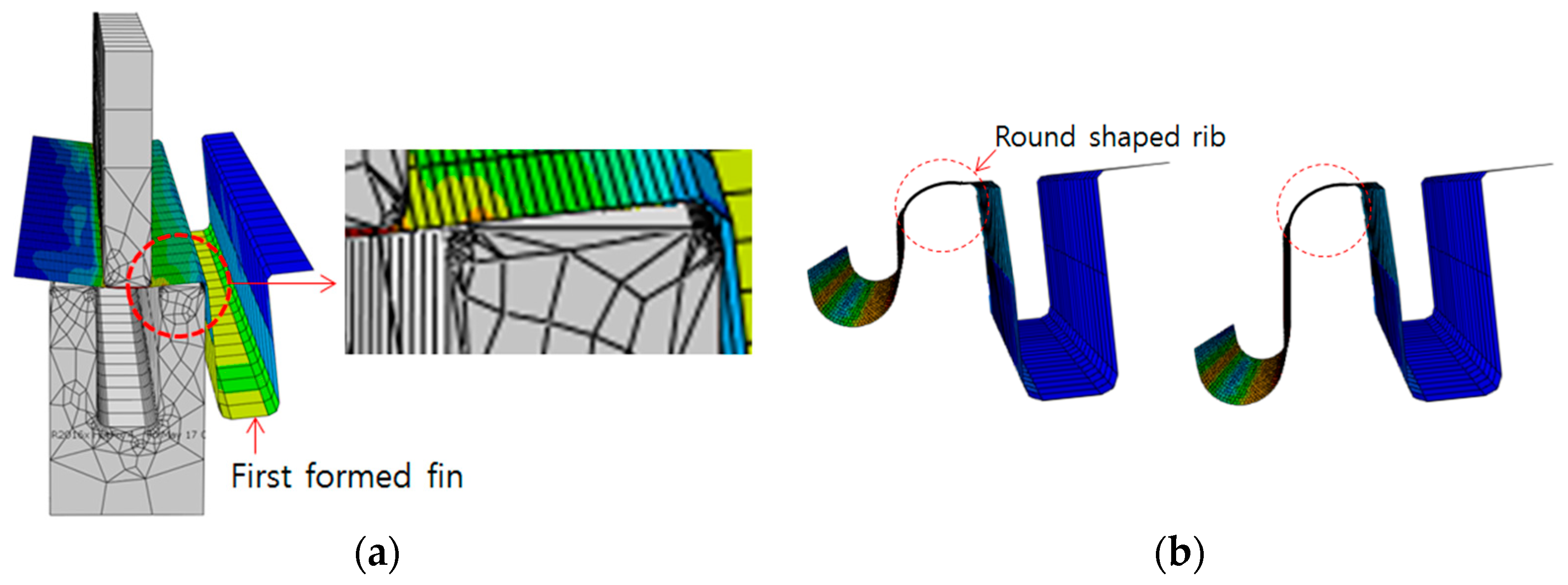
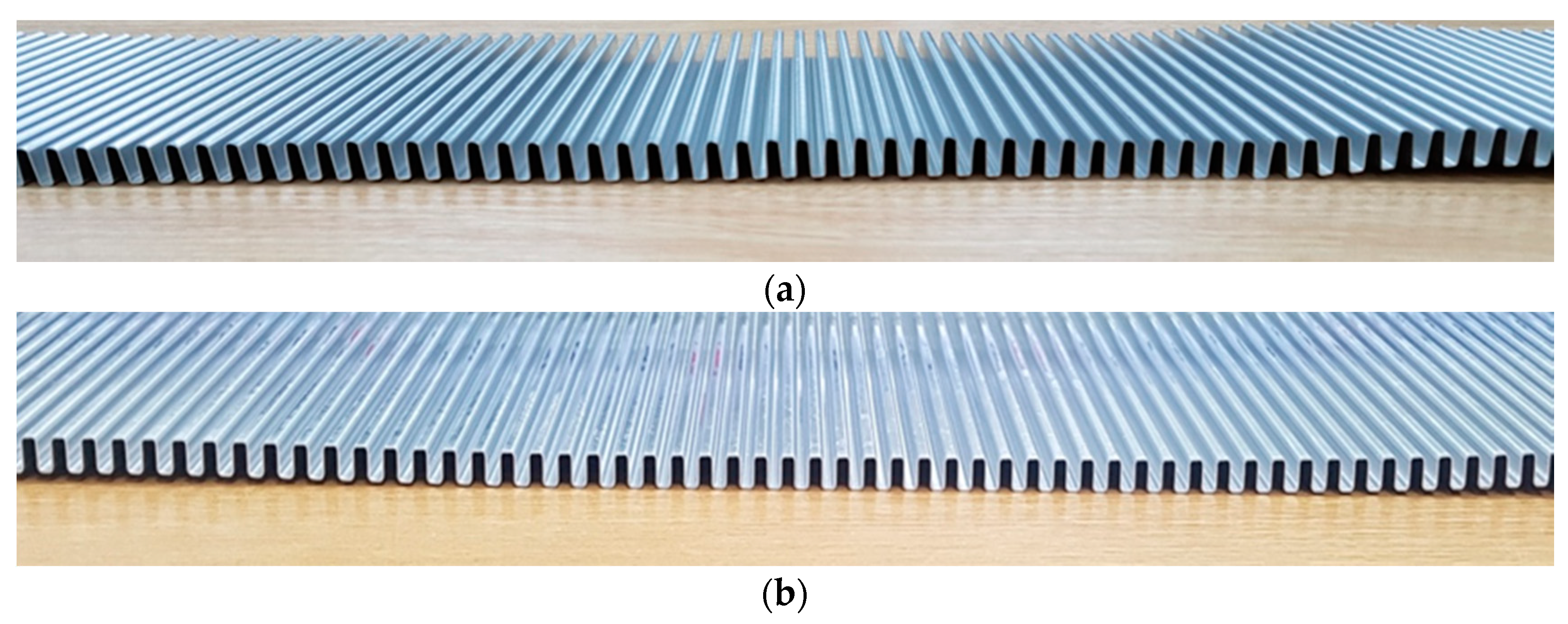
  • From the simulation, it was concluded that when the second fin and the third fin were formed, overforming occurred at the ribs. The overforming was also observed in the samples prepared in the laboratory with the results being the same as the simulation. The punch was modified so that the punch could compress the rib at the same time the fin was formed by the punch. The modified punch could produce the inner fins having right-angled ribs, however, the spring-back occurred during forming, resulting in the bottom of the fin width being 2.0 mm, while the top of the fin measured 2.20 mm and the depth of the fin measured 6.08 mm.

Acknowledgments

This work was supported by Kyungnam University Foundation Grant, 2019.

Conflicts of Interest

The author declares no conflict of interest.

References

  1. Shah, R.K.; Sekulic, D.P. Classification of Heat Exchanger. In Fundamentals of Heat Exchanger Design; John Wiley & Sons, Inc.: Hoboken, NJ, USA, 2003; pp. 1–74. [Google Scholar]
  2. Thulukkanam, K. Classification of Heat Exchanger. In Heat Exchanger Design Handbook, 2nd ed.; CRC Press Taylor & Francis Group: Boca Raton, FL, USA, 2013; pp. 1–27. [Google Scholar]
  3. Rajvir, S.D.; Pradeep, K.K.; Govind, M. Exergy based optimization and experimental evaluation of plate fin heat exchanger. Appl. Therm. Eng. 2016, 102, 80–90. [Google Scholar]
  4. Yorikata, M.; Toshihide, I.; Fumiko, K.; Noriyuki, S.; Masanori, T.; Tetsuo, Y.; Tetsuyuki, H. Development of structural design procedure of plate-fin heat exchanger for HTGR. Nucl. Eng. Des. 2013, 255, 248–262. [Google Scholar]
  5. Sai, K.M.; Sun, X.; Richard, N.C.; Raymond, R.U.; Richard, E.G.; Mike, W.P. Fabrication and design aspects of high-temperature compact diffusion bonded heat exchangers. Nucl. Eng. Des. 2012, 249, 49–56. [Google Scholar]
  6. Sommers, A.; Wang, Q.; Han, X.; T’Joen, C.; Park, Y.; Jacobi, A. Ceramics and ceramic matrix composites for heat exchangers in advanced thermal systems—A review. Appl. Therm. Eng. 2010, 30, 1277–1291. [Google Scholar] [CrossRef]
  7. David, C.D.; Michael, J.B.; Joshua, M.P.; John, Z. Expanded microchannel heat exchanger: Design, fabrication, and preliminary experimental test. P I Mech. Eng. A-J. Pow. 2012, 226, 532–544. [Google Scholar]
  8. Arun, M.; Carl, K.; Bengt, S.; Ramesh, K.S. Foam heat exchangers: A technology assessment. Heat Transf. Eng. 2012, 33, 42–51. [Google Scholar]
  9. Christophe, M.; Kevin, W.K. Fabrication and Performance of a Pin Fin Micro Heat Exchanger. J. Heat Transf. 2004, 126, 434–444. [Google Scholar]
  10. Chen, C.H.; Chen, C.T.; Wang, P.F.; Wang, Y.T.; Hsu, P.H.; Lin, C.L. A novel anatomical thin titanium mesh plate with patient-matched bending technique for orbital floor reconstruction. J. Cranio Maxill. Surg. 2018, 46, 126–1532. [Google Scholar] [CrossRef] [PubMed]
  11. Jin, B.J.; Lee, J.P.; Park, M.H.; Yun, T.J.; Song, Y.H.; Kim, I.S. A study on forming for plate-type heat exchangers of the Ti material. Procedia Eng. 2017, 174, 171–178. [Google Scholar] [CrossRef]
  12. Choi, S.W.; Park, S.H.; Jeong, H.S.; Cho, J.R.; Park, S.; Ha, M.Y. Improvement of formability for fabricating thin continuously corrugated structures in sheet metal forming process. J. Mech. Sci. Technol. 2012, 26, 2397–2403. [Google Scholar] [CrossRef]
  13. Kim, M.J.; Jin, C.K.; Kang, C.G. Comparison of formabilities of stainless steel 316L bipolar plates using static and dynamic load stamping. Int. J. Adv. Manuf. Tech. 2014, 75, 651–657. [Google Scholar] [CrossRef]
  14. Qinghui, H.; Dongming, Z.; Hao, F.; KaiKai, H. Investigation of stamping process of metallic bipolar plates in PEM fuel cell—Numerical simulation and experiments. Int. J. Hydrogen Energy 2014, 39, 13770–13776. [Google Scholar]
  15. Dou, S.; Xia, J. Analysis of sheet metal forming (stamping process): A study of the variable friction coefficient on 5052 aluminum alloy. Metals 2019, 9, 853. [Google Scholar] [CrossRef] [Green Version]
  16. Diogo, M.N.; Marta, C.O.; José, L.A.; Luís, F.M. Numerical study on the formability of metallic bipolar plates for proton exchan.e membrane (PEM) fuel cells. Metals 2019, 9, 810. [Google Scholar]
  17. Marciniak, Z.; Duncan, J.L.; Hu, S.J. Sheet deformation processes. In Mechanics of Sheet Metal Forming, 2nd ed.; Elsevier Ltd.: Amsterdam, The Netherlands, 2002; pp. 14–29. [Google Scholar]
  18. Abaqus/Explicit. Available online: https://www.3ds.com/products-services/simulia/products/abaqus/ (accessed on 7 March 2020).
Figure 1. Rectangular fins of the plate fin heat exchanger (unit: mm).
Metals 10 00395 g001
Figure 2. Shape of die and punch for forming simulation: (a) 3D and (b) 2D (unit: mm).
Metals 10 00395 g002
Figure 3. Method of mesh generation for blank and die: (a) blank and (b) die and punch.
Metals 10 00395 g003
Figure 4. Boundary condition for blank, punch, and die.
Metals 10 00395 g004
Figure 5. Progressive forming process for manufacturing inner fin.
Metals 10 00395 g005
Figure 6. The simulation results in terms of effective stress distribution for the single fin forming by stamping process: (a) first stage—V shape deformation; (b) second stage—V angle of the blank became narrower; (c) third stage—U shape deformation; and (d) last stage—fin shape deformation.
Metals 10 00395 g006aMetals 10 00395 g006b
Figure 7. The comparison of effective stress according to R1 of die and R2 of the punch: (a) second stage—V angle of the blank became narrower; (b) third stage—U shape deformation; and (c) last stage—fin shape deformation.
Metals 10 00395 g007aMetals 10 00395 g007b
Figure 8. The comparison of forming load according to R1 of the die and R2 of the punch.
Metals 10 00395 g008
Figure 9. Simulation results for second fin forming by stamping process: (a) blank compressed by punch and (b) rib deformation to a round shape.
Metals 10 00395 g009
Figure 10. Modified punch for compressing rib: (a) punch shape and(b) simulation result of formed rib.
Metals 10 00395 g010
Figure 11. Inner fin sample by progressive forming process: (a) punch and die in Figure 2 and (b) punch and die in Figure 10a.
Metals 10 00395 g011
Figure 12. Cross-sectional shape of the formed fin by a digital microscope (unit: mm): (a) punch and die in Figure 2 and (b) punch and die in Figure 10a.
Metals 10 00395 g012
Figure 13. The comparison of forming load between the simulation and experiment.
Metals 10 00395 g013
Table 1. Mechanical properties of Al1060.
Direction of SpecimenYield Strength (MPa)Tensile Strength (MPa)Elongation (%)Work Hardening Exponent
24.596.525.00.215
45°21.295.322.50.210
90°29.298.324.00.212
Table 2. Variables of simulation condition about edge radius of the punch and die.
Edge RadiusCondition 1Condition 2Condition 3
R11.0 mm0.7 mm0.5 mm
R20.7 mm0.4 mm0.2 mm

