Next Article in Journal
Liquation Cracking Tendency of Novel Al-Mg-Zn Alloys with a Zn/Mg Ratio below 1.0 during Fusion Welding
Next Article in Special Issue
The Effect of Hydrogen on Pore Formation in Aluminum Alloy Castings: Myth Versus Reality
Previous Article in Journal
Computational Modeling and Constructal Design Theory Applied to the Geometric Optimization of Thin Steel Plates with Stiffeners Subjected to Uniform Transverse Load
Previous Article in Special Issue
Numerical Simulation and Evaluation of Campbell Running and Gating Systems
 
 
Comment published on 3 April 2020, see Metals 2020, 10(4), 471.
Review

Recent Developments in Understanding Nucleation and Crystallization of Spheroidal Graphite in Iron-Carbon-Silicon Alloys

1
The Ohio State University, Columbus, OH and The University of Alabama, Tuscaloosa, AL 35487, USA
2
Azterlan, 48200 Durango (Bizkaia), Spain
3
Azterlan and Veigalan Estudio 2010, 48200 Durango (Bizkaia), Spain
*
Author to whom correspondence should be addressed.
Metals 2020, 10(2), 221; https://doi.org/10.3390/met10020221
Submission received: 27 December 2019 / Revised: 27 January 2020 / Accepted: 28 January 2020 / Published: 5 February 2020
(This article belongs to the Special Issue Dedicating to Professor John Campbell's 80th Birthday)

Abstract

:
The last decade has witnessed significant research efforts directed to the understanding of nucleation and crystallization of graphite and associated solidification phenomena, driven in part by the ever-growing interest in the use of spheroidal graphite cast iron in the manufacture of large castings, such as wind turbine parts. These applications raised new challenges to the production of sound castings, mostly because of the exceedingly long solidification times imposed by the size of the castings. These solidification conditions resulted in many instances in graphite degeneration with subsequent decrease in mechanical properties. Obviously, the subject of graphite nucleation and crystallization in cast iron is still in need of additional answers. Over the years, many reviews of the subject have been published. The goal of this paper is to provide an update on the advances achieved in comprehending the mechanisms that govern the nucleation and crystallization of spheroidal graphite and related imperfect morphologies from iron-carbon-silicon melts. In this analysis, we examine not only the crystallization of graphite in cast iron, but also that of metamorphic graphite (natural graphite formed through transformation by heat, pressure, or other natural actions), and of other materials with similar lattice structure and crystallization morphologies.

1. Introduction

Primitive people appear to have worked with meteoric iron long before learning to extract iron from iron ore. Thus, they were probably aware that meteoric iron sometimes contains graphite [1], as shown in Figure 1, but was certainly ignorant of the special properties that graphite can bring to iron, or iron alloys. Attempts to produce spheroidal graphite (SG) iron have been reported as early as 1938 when Carl Adey claimed to produce graphite nodules by fast solidification in irons with relatively high sulfur of 0.04% and no addition of spheroidizing elements [2]. However, it was not until 1943 when Keith Millis made a ladle addition of magnesium to cast iron through a Cu-Mg alloy and produced spheroidal graphite discovering ductile iron that the new material experienced an explosive expansion in the industry [3]. Indeed, analysis of AFS data on global casting production shows that between 1966 and 2017, the growth rate of ductile iron tonnage was an astonishing 22.5%/year [4]. Spheroidal graphite (SG) iron is, together with aluminum, one of the only two casting materials that have experienced continuous global growth since 1965, as shown in Figure 2. Even if only large SG iron castings alone are considered, the future of this material is more than promising. Indeed, the global wind turbine casting market size valued at USD 1.61 billion in 2015 will continue to experience fast-growing, because the ever-growing electricity needs resulting from urbanization and industrialization will drive the demand for renewable sources of energy, which will stimulate the usage of turbines that rely on SG iron castings, such as rotor hubs, axle pins, and main carriers [5].
This trend is the result of the continuous progress in understanding the processing -structure -properties paradigm of ductile iron, to include its solidification and its subsequent solid-state transformation during cooling or heat treatment. Review work on the solidification of cast iron has been periodically published, [6,7,8,9], with some addressing nucleation [10,11], while others focus on growth [12,13]. We also note Prof. Campbell’s work [14] that will be discussed in more detail later in this paper. The goal of this paper is to critically reassess the advances achieved over the last decade in comprehending the mechanisms that govern the crystallization of SG and related imperfect morphologies from Fe-C-Si melts (cast irons). Because of space limitations, only graphite nucleation and growth in Mg-treated irons will be discussed. However, this analysis will not be limited to cast iron. Available information on metamorphic graphite (natural graphite formed through transformation by heat, pressure, or other natural actions), and on other materials with similar lattice structure and crystallization morphologies, such as ice, will also be used to support the theories.

2. Some Basic Concepts

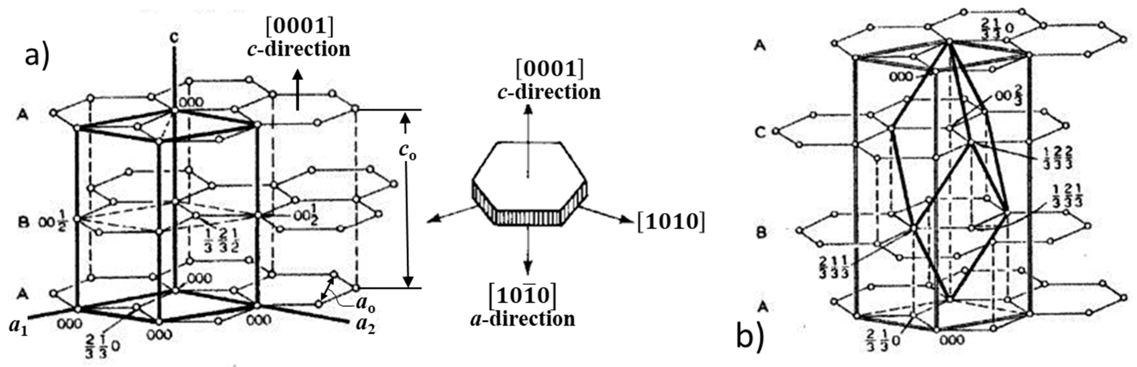
2.1. The Crystal Lattice of Graphite

Carbon can form sp-, sp2-, and sp3-hybridized bonds. Orbitals are regions around the nucleus where an electron can be found within a certain degree of probability. Hybridized bonds are mixtures between s and p orbitals. For example, in an sp3 hybridization, one s-orbital is mixed with three p orbitals to form four sp3 hybridized orbitals. Because of its ability to form hybridized bonds, carbon exists in a large number of forms to include graphite, diamond, nanotubes, fullerenes, and amorphous carbon [15]. The carbon allotropes with hexagonal lattice, include graphene, fullerene, carbon nanotube, and graphite. Thus, carbon is the unique element in the periodic table that has an allotrope in all dimensions, as shown in Figure 3. The other naturally occurring crystalline carbon, diamond, exhibits a face-centered cubic lattice above 900 °C, transforms into mono-layer graphene sheets aggregating into the layered structure typical for graphite (Figure 3c).
Both diamond and graphite also exist in two minor crystallographic forms: Hexagonal diamond and rhombohedral graphite. Experimentally observed crystal structures in graphite are commonly the AB hexagonal 2H (two hexagonal layers) structure and the ABC rhombohedral 3R (three rhombohedral layers) structure [17,18], as shown in Figure 4. Both hexagonal and rhombohedral structures were identified in spheroidal graphite in cast iron [19,20].
In addition to the common crystalline structure of carbon, hexagonal graphite and cubic diamond, polycrystalline samples transformed from graphite under high pressure and temperature have been reported to have higher hardness than single-crystal diamonds [21]. Subsequent experimental research [22] and ab-initio calculations [15] suggested that the structure of such samples could be a body-centered tetragonal carbon (bct-carbon) allotrope, a structure intermediate between that of graphite and hexagonal diamond.
As summarized in Reference [9], in the graphite crystal, the carbon atoms are arranged in a honeycomb lattice with the distance between atoms of 0.142 nm, and distance between planes of 0.335 nm. In the plane of the layers, the tri-electronic bond of each atom with its neighbors is a strong sigma-bond (a covalent bond resulting from the formation of a molecular orbital by the end-to-end overlap of atomic orbitals; 4.19 × 10⁵ to 5 × 10⁵ J/mol). The fourth electron is common for the layer giving the metallic properties of graphite. Weak van der Walls molecular forces exist between the layers (4.19∙103 to 8.37∙103 J/mol), as the large axial ratio, c/a ≈ 2.7, indicates. The hexagonal graphene monolayers are stacked in an ABAB sequence. The A and B layers are displaced by half of the c-axis spacing (Figure 4a). This configuration produces the faceted morphology and high anisotropic behavior of graphite [9,23].
As complete destruction of the graphite structure occurs only at about 4000 °C, the presence of some graphite aggregates in remelted cast iron, even at temperatures considerably higher than the liquidus temperature, is to be expected.
The prism plane is a high energy plane at which impurities absorb preferentially. Because of the difference in the bonding forces between the a- and c- directions atoms are added easily in the a-direction, but with lower probability in the c-direction. Thus, it is assumed that the preferred growth habit for graphite is in the [1010] a-direction, producing a sheet. It explains the graphite flakes found in natural graphite and the graphite lamellae in gray cast iron. However, in Ni-C, Co-C, and Fe-C alloys (steel and cast iron) spheroidal graphite can be produced, where the graphite aggregate appears to extend in the c-direction rather than the a-direction. This departure from the Bravais’s rule and the Gibbs-Wulff theorem has been a topic that continues to stimulate research. However, before engaging on the difficult path of explaining the various theories of graphite growth a small incursion in the study of the growth environment, i.e., the melt from which the graphite crystallizes is deemed necessary.

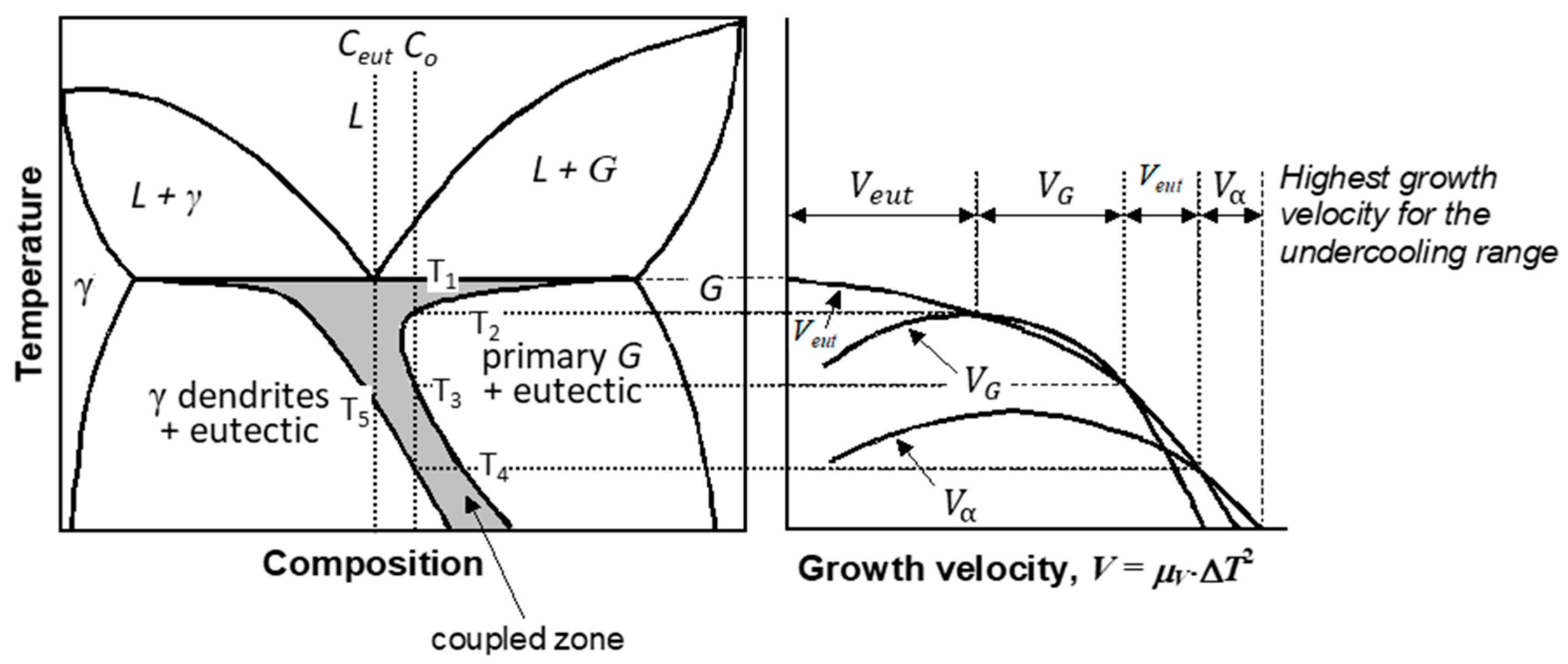
2.2. The Asymmetric Coupled Zone

To understand solidification of SG iron, and for that matter of any type of cast iron, it is necessary to master the concept of asymmetric coupled zone in the Fe-C diagram (Figure 5), an application by Kurz and Fisher [24] of a theory by Burden and Hunt [25] (see Reference [26] for a more detailed discussion), as it complicates the use of the Fe-C-Si equilibrium phase diagram in explaining the solidification structure. The coupled zone is the region of cooperative two-phases eutectic solidification. It is symmetric for regular eutectics, but asymmetric for irregular ones, such as lamellar graphite cast iron. It was originally introduced for the austenite (γ)/lamellar graphite (LG) eutectic, but calculations by Lux et al. [27] demonstrated that an asymmetric coupled zone also exists for the divorced γ/SG eutectic.
Consider the hypereutectic composition Co in Figure 5. If the cooling rate imposes an undercooling, such as the solidification starts immediately under the eutectic equilibrium temperature, T1, the growth velocity of the eutectic is higher than that of the γ dendrites and of the primary graphite resulting in solidification of the γ/G eutectic. However, if higher undercooling is achieved so that solidification starts under T2, the graphite phase grows faster. Eutectic can solidify again if the undercooling brings the temperature lower than T3. If the undercooling is so high that solidification starts under T4, austenite has the highest growth velocity and will solidify. Thus, depending on the undercooling, a hypereutectic iron can solidify fully with a γ/G eutectic, or even with an austenite + eutectic structure. Similarly, an iron of eutectic composition Ceut, may exhibit austenite dendrites in the microstructure if it solidifies at an undercooling lower than the temperature T5. As SG iron solidifies with higher undercooling than lamellar graphite iron, solidification with an asymmetric coupled zone is one of the reasons why in most ductile irons, dendrites are seen in the room temperature microstructure.

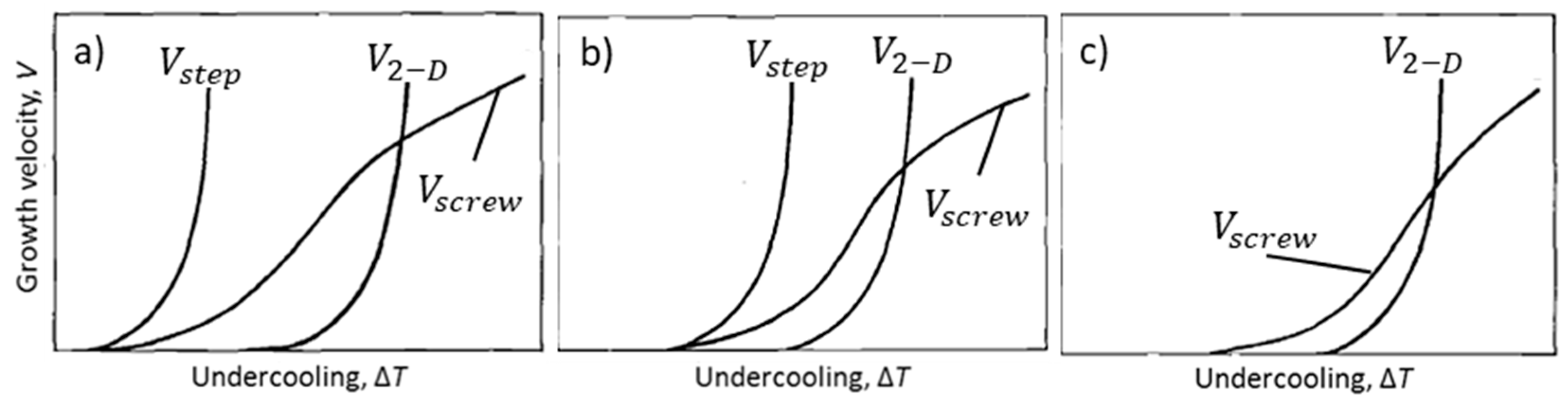
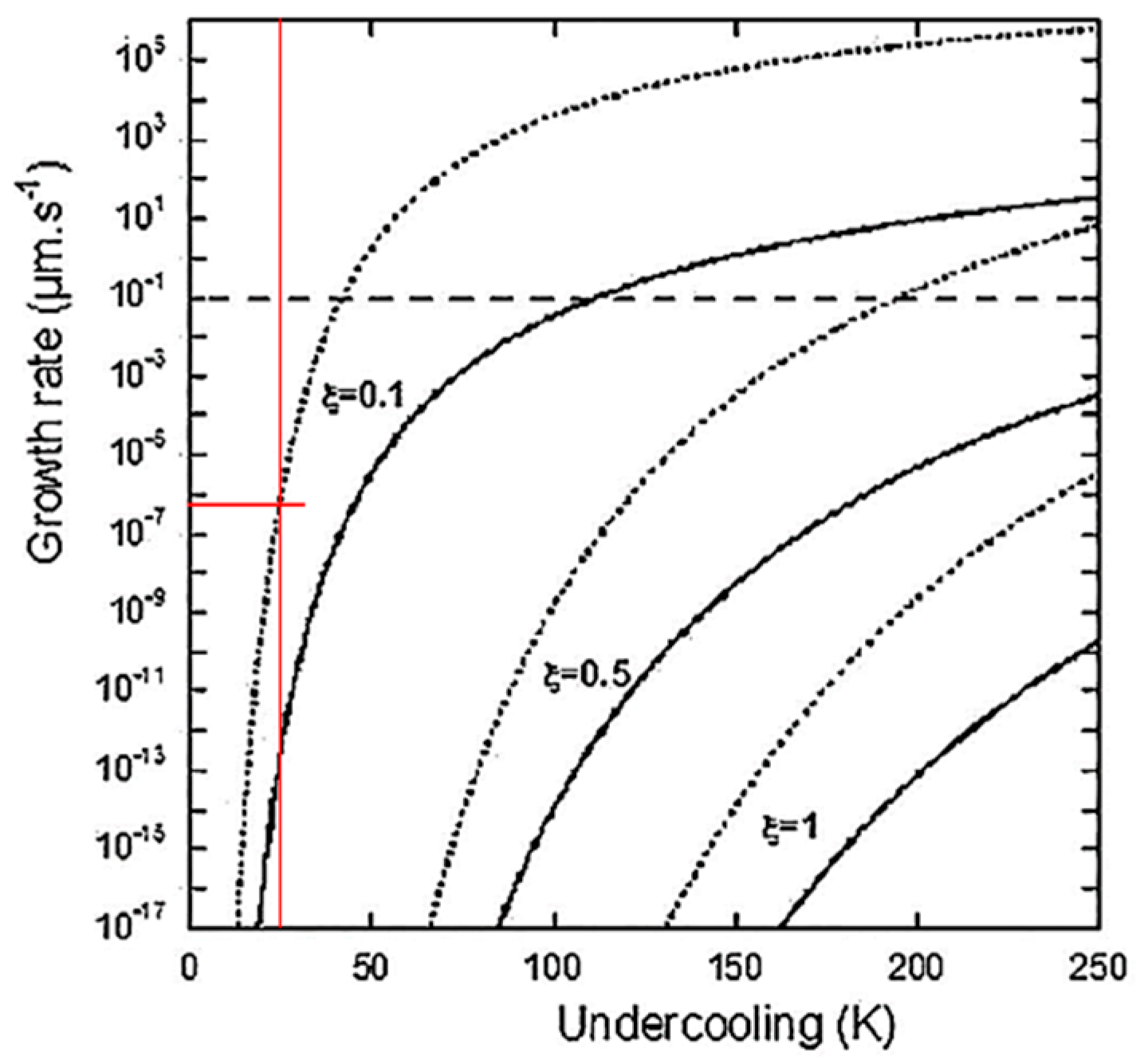
2.3. Growth Mechanisms for Crystals Relevant to Graphite Growth

The growth of a graphite crystal starts with the formation of 2-D graphene sheets that develop in the a-direction. Crystallization of graphite from Fe-C melts begin with the stacking of the graphene sheets in the c-direction into hexagonal faceted graphite platelets that are the basic building blocks of the graphite aggregates. Such platelets, 10–30 nm thick and hundreds of nanometers in length, have been found in graphite spheroids from carbon steel [28] (Figure 6a), in Mg-treated SG iron [29] (Figure 6b), and in compacted graphite (CG) aggregates as hexagonal faceted graphite platelets with nanometer-height in the c-direction and micrometer width in the a-direction [30] (Figure 6c). To produce a graphite aggregate as found in cast iron, the platelets must thicken and aggregate.
The operating growth mechanism of a crystal is a function of the nature of the interface and of the driving force (undercooling, supersaturation). For atomically rough (non-faceted) interfaces, such as dendritic austenite, the interface advances through a continuous growth that requires small driving forces. The growth rate is controlled by solute transport to the interface. For atomically smooth (faceted) interfaces crystals, such as graphite or ice, the interface advances through lateral growth, which requires larger driving forces. Two mechanisms are known for lateral growth, two-dimensional (2-D) nucleation of a new layer, and defect-controlled growth, where crystal defects are step sources for a new layer. The latter requires significantly lower driving force. Thickening of the platelets occurs through layer growth in the c-direction. The possible mechanisms include: 2-D nucleation and defects, such as screw dislocation or rotational stacking faults.
Because 2-D nucleation (Figure 7a) is slow and could not explain graphite thickening during graphite growth, a variant of 2-D nucleation, poly-nucleation (PNG), was considered. It assumes that a large number of 2-D nuclei form on the surface of a growing crystal, and also on top of the already growing islands before the layer spreading is complete (Figure 7b). It has been shown to occur on graphite plates in a Ni-C alloy (Figure 7c), but there is no experimental evidence that demonstrates that this mechanism contributes to SG growth. However, when comparing Figure 7b with Figure 8a, it seems more likely that the platelets in Figure 7c result from dislocation spiral growth.
Frank [35], and then Minkoff, Lux and coworkers [32,34] argue that growth occurs from steps on the graphite layers related to such defects as screw dislocations and twisted boundaries (Figure 8). Some early investigators recognized the role of such dislocations in generating spiral growth in the c-direction [7,36,37,38]. Electron microscopy studies by Delavignette and Amelinckx [39] on single crystal flakes of natural graphite predicated the existence of both basal plane and non-basal dislocations. Henning [40] found concentrations of screw dislocations whose Burgers vector parallels the c- axis in single crystals of natural graphite and in pyrolytic graphite. More recently, examples of spiral growth for pyrolytic graphite spheres [28], and for both lamellar [41], and compacted [42] graphite were found.
To produce the large variety of graphite morphologies found in cast iron the graphite platelets aggregate by a variety of mechanisms controlled by supersaturation (the difference in chemical potential between a carbon atom in solution and that in the graphite crystal). The basic mechanisms and some examples of graphite growth and of crystal growth in analogous materials are summarized in Figure 9, Figure 10, Figure 11, Figure 12, Figure 13, Figure 14 and Figure 15.
Foliated crystals are assemblies of thin plates connected by thin protrusions growing perpendicular to the basal planes, and separated by solvent impurity layers, identified by Saratovkin [43] who used the concept to explain iron entrapment between graphite layers during graphite growth in cast iron. The effect of solutal driven constitutional undercooling on foliated crystal growth is explained in some detail in Reference [42]. When crystals grow parallel to one another tiled-roof configurations result (Figure 9). If the overall growth of the foliated crystal is less organized, dendritic structures are produced (Figure 10). Stacking of the crystals in the [0001] direction generates columns (Figure 11).
Disclinations are line defects corresponding to “adding” or “subtracting” an angle around a line. The positive wedge disclination mechanism was suggested by Amelinckx et al. [45] who argued that the initial graphite layer adopts a slitted dome-shaped configuration by introducing a fivefold carbon ring in the six-fold carbon network. Successive sheets are rotated with respect to the previous one over a constant angle, thus, producing a micro-spiral cone around a “disclination” with a fivefold carbon ring core (Figure 12a).
When inserting a wedge into the basic hexagon a negative wedge disclination defect is produced (Figure 13a). It was used to explain macro-spiral growth in metamorphic graphite (referred to as helical growth in this paper), where upward spiraling plates were documented with hexagonal cavities in the middle of the aggregate (Figure 13b).
In their circumferential growth (or curved crystal growth) mechanism, Sadocha and Gruzlesky [49] argue that bending of graphite platelets growing in the a-direction can occur by the movement of steps around the surface of spheroids (Figure 14). They claim that this growth mechanism explains observations of graphite spheroids in high-purity Fe-C-Si alloys without Mg or Ce additions.
Hopper crystals belong to the family of skeletal crystals which develop when atoms are added more rapidly to the edges and corners of a growing crystal than to the centers of crystal faces, resulting in either branched dendritic habit, or hollow stepped depressions (hoppers) (Figure 15a). Hopper crystals are found in many materials, such as ice (Figure 15b), halite, bismuth, galena, gold and quartz.

2.4. Effect of Impurities in the Melt

It is well established that graphite crystallization is significantly affected by the presence of melt impurities in the melt in which it grows, even when these minor elements are in amounts of less than 0.1%. They may have a beneficial effect, promoting nucleation and spheroidization, or a negative one, causing graphite degeneration. The primary source of these elements is from the furnace charge materials, such as steel scrap, pig iron, and cast-iron returns. Other minor elements are intentionally added during preconditioning of the melt or as inoculants.
Minor elements can be grouped into three categories: Residual elements, trace elements, and tramp elements. Residual elements (e.g., S, P, Ti, Cr, V, Nb) originate from the charge materials. Trace elements (e.g., Al, As, B, Ba, Bi, Ca, Cd, Ce, La, Mg, Pb, Sb, Se, Te, Zn, Zr) are introduced during melt treatment. Tramp elements refer to any residual or trace element that degrades the microstructure and properties of cast-iron. The acceptable levels of all these elements and their effect on the microstructure have been summarized by Voigt [51].
When limiting our interest to only SG iron a different classification of impurities can be suggested: (a) Elements promoting graphite nucleation (Al, Ca, Ba, Sr, Ce, La, S, Ti, N, Zr); (b) reactive impurities favoring graphite spheroidization (Mg, Ca, Y, Ce, lanthanides); (c) surface-active impurities that tend to produce degeneration of spheroidal graphite into chunky, spiky and other forms (S, O, Al, Ti, As, Bi, Te, Pb, Sb). All elements decrease the surface energy of liquid Fe-C alloys. Ni, Cu and Si slightly reduce the surface energy, while Ca, Mg, Ce, S, Se, and Te have a much stronger effect. By changing the crystallography of the growth phases and the constitutional undercooling of the melt, the impurities affect graphite crystallization.
Reactive impurities (Mg, Ce) remove surface-active impurities generating high surface energy in the melt. For Mg-treated irons the maximum surface energy is reached at 0.015% Mg, a level lower than that required for SG formation [52]. Upon holding at temperature, the surface energy decreases because of Mg removal from the liquid by oxidation and vaporization (fading effect).
McSwain and Bates [53] performed iron/graphite surface tension measurements on Fe-C-Si0.037Mg and Fe-C-Si-0.05S alloys and use the data to calculate the interface energy. The data summarized in Table 1 show that for the Mg-treated iron the lowest energy is associated with the basal plane, while for the sulfur iron it is with the prism plane.
It may be summarized that various solutes in molten iron will affect graphite morphology through [54]:
  • Increased graphite/liquid interface undercooling because of the attachment of impurities (e.g., Mg, Ce, O) to the graphite surface, and rejection of solute (Mg, Bi, Pb, Sn) into the liquid;
  • Decreased graphite/liquid interface undercooling because of lower surface energy ensuing the adsorption (weak van der Waals forces) of surface-active elements (S, O);
  • Change of the graphite crystal habitus because of the adsorption of reactive or surface-active elements; this effect could also be understood in terms of bending of the graphene layer because of attachments of elements.
Impurity elements also have a significant influence on graphite nucleation, as they form a variety of compounds, such as sulfides, oxides, nitrides and others that can act as nuclei. To act as nucleation sites, these inclusions must satisfy some specific conditions, including high stability at elevated temperatures, high probability of formation (low standard free energy), good crystallographic compatibility (isomorphism or epitaxy with low lattice disregistry), fine dispersion in the melt (1–3 μm) and high surface energy between the liquid and the nucleant. For SG iron, a clear requirement of a good nucleant is strong affinity for oxygen and sulfur.

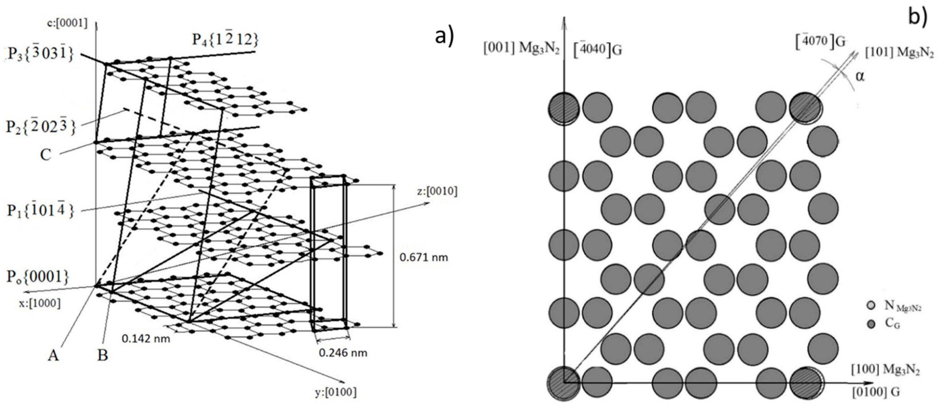
2.5. Crystallographic Considerations

Crystallographic compatibility implies that the substrate must have a coherent or semicoherent interface with the solid to be nucleated. According to Turnbull and Vonnegut [55], the crystallographic compatibility may be measured through the linear disregistry, δ :
δ = ( a n a S ) / a S
where aS and an are the interatomic spacing along with shared low-index crystal directions in the solid nucleus and the, nucleant, respectively. In the evaluation of nucleants for pure iron by Bramfitt [56], a planar disregistry of 5.9% was considered to be indicative of a highly effective nucleant, and one of 11.2% moderately effective. Bramfitt also argued that the Turnbull/Vonnegut equation for linear disregistry could not be applied to crystallographic combinations of two phases with planes of differing atomic arrangements (e.g., cubic Fe and hexagonal graphite), and proposed a planar disregistry equation that included the angular difference between the crystallographic directions within the plane:
δ ( h k l ) n ( h k l ) S = i = 1 3 | ( d [ u v w ] S i   c o s θ ) d [ u v w ] n i | 3 · d [ u v w ] n i   100
where ( h k l ) S is a low-index plane of the substrate, [ u v w ] S is a low-index direction in ( h k l ) S , ( h k l ) n is a low-index plane in the nucleated solid, [ u v w ] n is a low-index direction in ( h k l ) n , d [ u v w ] n , is the interatomic spacing along [ u v w ] n , d [ u v w ] S is the interatomic spacing along [ u v w ] S , and θ is the angle between [ u v w ] S and the [ u v w ] n . Highly effective inoculants have low disregistry, typically <12. A parabolic relationship between the undercooling and the disregistry ( Δ T c r = 0.25   δ 2 ) was found.
The earliest work on inoculation was initiated by Geilenkirchen [57] who, in 1908, observed that certain additions, such as ferrosilicon, Ca or V to liquid cast iron significantly affect its solidification. However, it was not until 1922 that the first industrial process for the inoculation of gray iron with calcium silicide was patented by Meehan [58]. By 1930, systematic studies on the inoculating effect of many elements (Na, Ca, Li, Mg, Ca, Sr, Ba) were conducted by Piwowarsky [59]. Today, most used inoculants are based on ferrosilicon. However, pure Si or pure FeSi are not effective [60,61], as the efficiency of the inoculant depends on the presence of minor elements, such as Ca, Ba, Sr, Al, Zr, Ti, lanthanides, and others [50,62,63,64,65,66,67,68,69].

3. Nucleation of Graphite during Solidification

Commercial cast iron, a multicomponent Fe-C-Si based alloy, contains significant amounts of preexisting impurities, such as undissolved graphite, solid films of oxides [14,70], and a variety of other inclusions, such as nitrides, sulfides, and silicates. Intentional additions of chemicals are made during a two-stage melt treatment (Mg-treatment followed by inoculation) with the goal of spheroidizing the graphite and increasing the number of graphite nodules. Thus, additional oxide and nitrides may result from metal-gas reactions, while metal-carbon reactions can produce carbides, and metal-sulfur reactions can generate sulfides. Further, these inclusions can combine into complex carbonitrides and oxysulfides, and all of them can act as SG nuclei. Graphite nucleation occurs in both stages of the melt treatment. Inoculation is not only creating new nuclei but is also modifying the nuclei produced during the Mg-treatment. The thermodynamics controlling these reactions is complicated by the transient nature of the iron melt in terms of composition and temperature. Thus, theories of graphite nucleation cover a wide range of possibilities, including homogeneous, heterogeneous, and sequential (multi-stage) nucleation.
Earlier work on assessing the effectiveness of an inoculant on graphite nucleation relied on indirect methods, such as the “nodule count”, that is on evaluating the number of graphite spheroids before and after inoculation. For example, while the nature of the nuclei was not specified, Kanetkar et al. [71] demonstrated that residual amounts of Pr, Nd, Y, La, or Ce in the FeSiMg alloy considerably increased the nodule count. Thus, the lanthanides and Y could be considered to be significant participants in graphite nucleation. Modern research that aims at collecting evidence on the chemistry and crystallography of the various compounds found to be nucleants relies heavily on transmission and scanning electron microscopy (TEM, SEM) coupled with energy dispersive X-ray analysis (EDX), as well as field emission-type Auger electron spectroscope. Extensive use of samples quenched during solidification allowed the identification of nuclei in a large number of graphite spheroids, as the probability of identifying nuclei on the metallographic image in small nodules is higher than that for large nodules [72]. This approach was successful in identifying the composition of compounds and families of chemical compounds that commonly provide nuclei for SG crystallization during the liquid/solid and solid/solid transformations.

3.1. Homogeneous Nucleation

An early (1947) theory by Boyles [73] argued that graphite grows from small size crystalline graphite already present in the melt. Steeb and Maier [74] advocated that in melts with more than 3.5% C there exist short-range order regions, which are carbon clusters containing approximately 15 atoms. At carbon contents consistent with the short-range order, the melt exhibited increased viscosity [75]. These and other [76,77] experiments indicate that either C n or ( F e 3 C ) n clusters (or molecules) that exist in dynamic equilibrium in molten Fe-C alloys may serve as nuclei for graphite.
Detailed SEM examination of graphite spheroids observed in vacuum-melted high-purity Fe-C-Si alloys produced from ultrapure zone-refined iron by Dhindaw and Verhoeven [78] did not find any impurities in the center of the spheroids. This implies homogeneous nucleation of SG. Stefanescu et al. [54] demonstrated that in low-carbon gray irons, graphite nucleates at the austenite/liquid interface without the presence of any foreign inclusions. Fredriksson [79] observed that following the dissolution of ferrosilicon in liquid cast iron, SiC crystals could be formed in the complex diffusion zone around the dissolving particles. The local supersaturation of C and Si in the melt subsequent to the SiC dissolution, may provide the necessary driving force for homogeneous nucleation of graphite. The fading effect was explained by the homogenization of C and Si in the melt through convection and diffusion.

3.2. Nucleation on Oxides

Oxides have been identified in the nuclei of SG by a large number of investigators, including Heine and Loper [80], Poyet and Ponchon (MgO, SiO2) [81], and Jacobs et al. (Mg, Al, Si, Ti oxides) [82]. Francis [83] found round, 2–5 µm diameter inclusions of CeO2 and Fe2O3 with some MgO, in iron treated with a Fe-46Si-3.5Mg-2.2RE alloy. Silicates were not identified. Gad and Bennett [84] suggested two-stage nucleation initiated on CaO, with subsequent formation of Ca-silicate and silica on the oxide.
Data on the standard free energy of formation and on the melting temperature of oxides are summarized in Table 2 [85]. Most data were calculated with the thermodynamics software FactSage; others were obtained from the literature, as indicated.
Data in Table 2 reveal that double and complex oxides have lower standard free energy, and thus, higher probability of formation, than single ones. The highest probability of formation is by far that of the complex oxide 2MgO∙2CaO∙14Al2O3 (Mg-Ca aluminate), followed by the double oxide 5CaO∙4TiO2 (Ca titanate). Calcium, aluminum and magnesium silicates also exhibit a high probability of formation. This is why single oxides are only seldom found as nuclei for SG. Indeed, a recent study on a very large number of nuclei could only find two cases of one-stage nucleation on single-compound inclusions, i.e., iron oxide and aluminum oxide [85]. However, two-stage nucleation on a nucleus with a (La,Ce)O core and an MgO shell was also observed (Figure 16a) [87].
The free energy of formation listed in tables is valid for reactions between pure elements. However, the real reaction energy in solution is defined by element activity and could be significantly different from that of pure elements. In particular, Ca reactions with sulfide formation could be more favorable than oxide formation in cast iron. Thus, the hierarchy listed in Table 2 and Table 3 may be considerably different for cast iron melts.

3.3. Nucleation on Sulfides

As early as 1966, Warrick [67] suggested that nuclei for lamellar and spheroidal graphite are composed of complex oxides and sulfides, including MgS, CeS, and LaS. Then, other investigators suggested these and other sulfides as potential nucleants: Stransky and Rek (MgS) [88], Mercier et al. (MgS, CaS) [89], Nieswaag and Zuithoff (Te-Mn sulfide) [90], Jacobs et al. (CaS, MgS, SrS) [82]. Lalich and Hitchings [91] concluded that in laboratory melts nuclei were primarily Mg, Ca or RE sulfides, while in cupola irons, the nuclei were probably complex mixtures of sulfides and silicates.
Jacobs et al. [82] developed the first two-stage nucleation theory of double-layered (cored) nucleation for SG. They contended that SG nucleates 1 µm duplex sulfide-oxide inclusions having a core made of Ca-Mg or Ca-Mg-Sr sulfides, and an outer shell of complex Mg-Al-Si-Ti oxides. The x-ray diffraction data showed that the first few graphite layers, adjacent to the (111) oxide, had a dilated lattice (0.264 nm, instead of 0.246 nm). It was suggested that the spacing within the graphite layers decreases away from the oxide until the unconstrained spacing is reached. Based on these findings it was proposed that initial sulfides serve as catalytic substrates for oxides, on which the spheroidal graphite nucleates. The sequence in the duplex structure of the inclusions (sulfide core and oxide shell) may be surprising in light of the fact that oxides have lower energy of formation that sulfides.
Experimental work by Igarashi and Okada [92] also supported a two-stage sequential theory, but in a different sequence. Their SEM-EDS analysis produced a (MgCa)S spherical nucleus with an MgO core.
It has been thoroughly documented that MnS or complex (MnX)S compounds which have low crystallographic misfit with graphite and have a core of complex Al-Ca-Mg oxide, e.g., References [93,94,95,96,97,98] are nucleants for lamellar graphite. However, MnS was never found in the center of graphite nodules, and thus, it is not a nucleant for SG.
As it can be observed from Table 3, the sulfides of elements from group II have high melting points and lower energy of formation than the carbides. They have a face-centered cubic structure with lattice parameters of 0.5 to 0.6 nm, very similar to that of their carbides.
Data in Table 2 indicate that oxides have lower energy of formation than the sulfides of the same metal. However, as the free energy values are rather close, and the iron melts are chemically nonhomogeneous, it is not necessary that the formation of oxides during cooling precedes that of sulfides. It is quite possible that they form simultaneously at various locations in the melt, as sulfides have been found as one-stage nucleants for SG (Figure 16b).

3.4. Nucleation on Carbides

Experiments by Lux and Tannenberger [60,99] showed that a number of pure metals, such as Li, Ca, and Ba, can be effective in promoting graphite nucleation in cast iron. They suggested that these and all elements from groups I (Na, K), II (Mg, Ca, Sr, Ba) and III (Y, La) from the periodic table, when introduced in molten iron, form salt-like carbides with cubic structure. The C 2 2 ions develop epitaxial planes with the graphite, and thus, constitute nuclei for graphite. Graphite is growing parallel to the (111) faces of the CaC2 lattice. The distance between the (111) CaC2 planes (0.341 nm) and the (0001) graphite layers (0.335 nm) is very close, giving a linear disregistry of 1.53% (Table 4), which is indicative of good crystallographic compatibility with graphite. Other elements from group II have similar lattice parameters. However, to the best of our knowledge, there is no report of carbides of elements in groups 1, II or III acting as nuclei for SG. This is probably because carbides have higher energy of formation than either oxides or sulfides and are seldom present in the melt. While TiC was identified in a graphite spheroid (Figure 16c), the carbide is most likely a complex carbonitride, Ti(CN), as also suggested in work by Sun and Loper [100].

3.5. Nucleation on Nitrides

As seen in Table 3, Zr, Ti and Al nitrides have lower energy of formation than sulfides, and thus, they should be able to act as nucleants in ductile iron. While TiC rarely appears as a nucleant, the carbonitride Ti(CN) frequently is. Planar disregistry calculation [101] in Table 5 indicate that TiN has better crystallographic compatibility with graphite than TiC (δ = 1.11 compared to δ = 2.69). As TiN also has a lower energy of formation than TiC (−580 vs. −163 kJ/mol), and as nitrogen is always present in cast iron, Ti(CN) is a more probable inclusion to act as nucleant than TiC alone. In most cases, the titanium carbonitride was found to nucleate on sulfides (Figure 17a) or oxides.
Mg-Si nitrides were first reported as potential nuclei for SG by Mercier et al. [88]. Then, Igarashi and Okada [91], and then Nakae and Igarashi [102] confirmed the Mg-Si-Al nitride as a compound contributing to the nucleation of SG. Solberg and Onsoien [103] studied the crystallographic structure of an Al-Mg-Si nitride found in the center of an SG and concluded that it has a trigonal crystal structure with the composition Mg2.5AlSi2.5N6. The parameters of the fundamental cell deviated only 1–3% from the parameters of the hexagonal AlN. They also stated that there is no obvious crystallographic similarity between the nitride particle and the graphite.
Following a thermodynamic analysis [104], the relevant energies of formation from Table 3 are: −580 kJ/mol for TiN, −538 kJ/mol for AlN, −118 kJ/mol for Mg3N2, and −163 kJ/mol for TiC. The Ti and Al nitrides have relatively low energies of formation, higher than MgO (−858), but lower than MgS (−294). It appears that some combination of Mg3N2 with AlN, and of TiC with TiN, are occurring, as nucleation was documented on Mg-Al-Si nitrides and Ti(CN), but was only seldom, if at all, reported on Mg3N2 or TiC. Further, the Mg2.5AlSi2.5N6 compound identified by Solberg and Onsøien can be written as the stoichiometric compound (AlN)6(Mg3N2)5(Si3N4)5 in which the aluminum nitride is the dominant compound. However, it is also possible that the complex nitride is associative, resulting from the successive growth of the three nitrides. As the energy of formation of aluminum and titanium nitrides is positioned between that of MgO and MgS, both proven as common nuclei for SG, it is sufficiently low for nucleation of graphite. The complex Mg-Al-Si nitride in Figure 17b,c appears also to be thermodynamically capable of acting as a substrate, in particular, if the compound is associative, with Mg3N2 nucleating on AlN. This is also true for the Ti(CN) nucleated on Mg(CaS) in Figure 17a.
To demonstrate the capability of these nitrides to serve as nuclei for spheroidal graphite disregistry calculations were performed. The planes Po to P4 of the graphite lattice in Figure 18 were selected for the calculation of planar disregistry with Mg3N2 that has a cubic crystalline structure. Small disregistry values of 0.59 and 0.125% were calculated for Po and P2, respectively (Table 5), suggesting near-perfect coherency, and hence, the possibility of graphite nucleation on Mg3N2. For these two planes cells with dimensions almost identical with the unit cell of Mg3N2. Were found.
The Mg3N2/graphite linear disregistry calculation also provided encouraging results, with a 4.41% linear disregistry between the Mg-Mg and the C-C atoms, and a range of 0 to 10.06%, between the N-N and C-C atoms. This data also supports the graphite nucleation ability of Mg3N2 [104].
A similar analysis was conducted for AlN, which has a hexagonal lattice. Calculations were performed for the disregistry between a lateral face of the AlN crystal and the cell in plane P4: ( 1 2 ¯ 12 ) in Figure 18a, and a disregistry of 7.586% was obtained (Table 5). This is higher than that of Mg3N2, but still in the range accepted for nucleants. Moreover, note that AlN has a low energy of formation of −538 kJ/mol (Table 3).

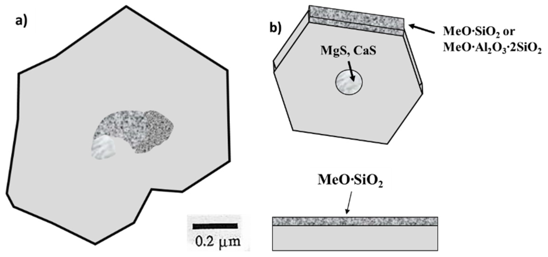
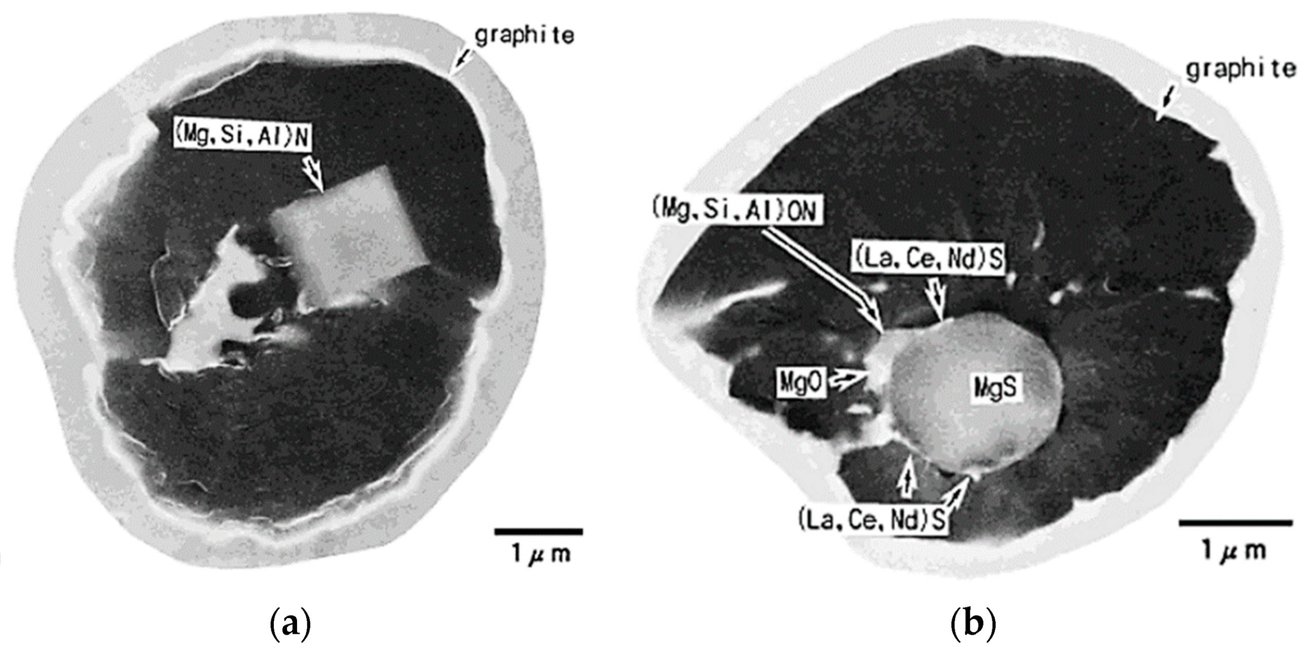
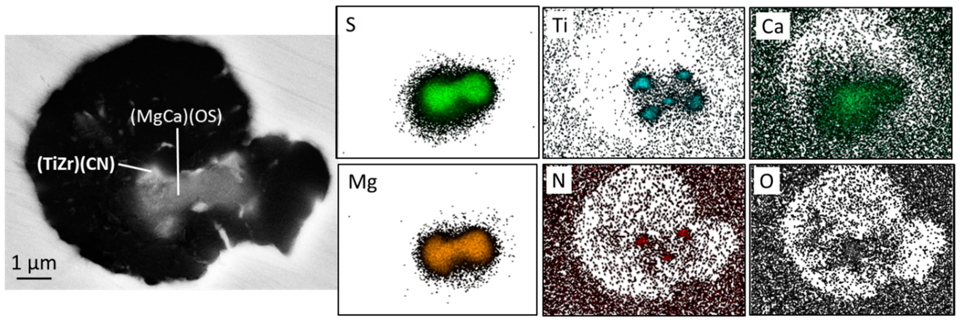
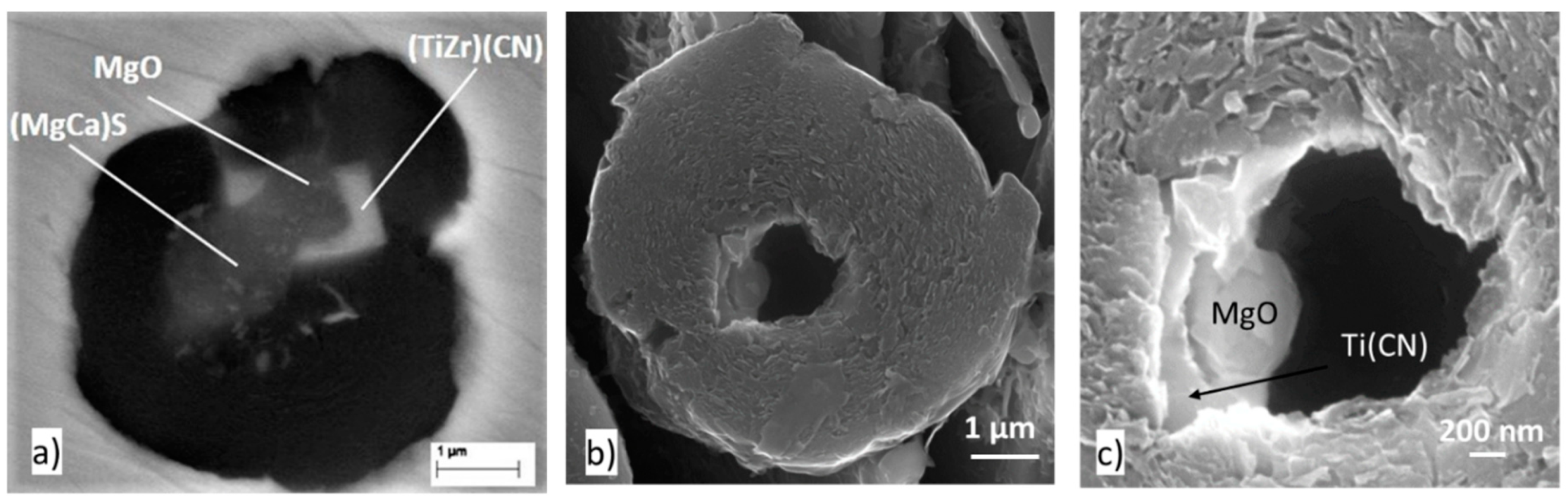
3.6. Nucleation on Complex Compounds

Early work documented that the majority of graphite nodules in SG iron are associated with non-metallic inclusions, mainly MgCa sulfides [91,105] or complex oxides and sulfides [67]. Analysis of the experimental data cited in this work leads to the conclusion that the majority of nuclei found in SG are complex compounds. In recent research by Alonso et al. [87] in which about 1000 graphite nodules were analyzed, a variety of different inclusions of complex composition that included sulfides, oxides, nitrides and silicates was found in the nuclei. Magnesium sulfide sometimes accompanied by TiC was found in about 63–75% of the nodules. Mg-Ca oxysulfides were found in 10–13% of the spheroids.
A further significant contribution to the two-stage nucleation theory of SG is the silicate theory developed by Skaland et al. [86] who analyzed nucleation in irons with the composition in the range 3.43–3.8% C, 2.24–2.64% Si, 0.002–0.004% S, 0.033–0.064% Mg, 0.009–0.015% Ti. They reported that the nuclei are hexagonal double layer compounds, with an Mg-Ca sulfide core surrounded by silicates (MgO SiO2 and 2 MgO SiO2) or oxides that have low potency (large disregistry) on which epitaxial graphite growth occurs (Figure 19). Some aluminum can enter the deoxidation products forming more complex phases, such as MgO·Al2O3 or MgO·Al2O3·SiO2. These silicates (complex oxides) and others have good planar disregistry with graphite, supporting their qualifications as graphite nuclei (Table 6).
Another example of two-stage nucleation was provided by Igarashi and Okada [92] who found graphite spheroids nucleating on a CaO, MgO, Al2O3 or MgO/MgS core, enveloped by a complex nitride (MgSiAl)N.
The first three-stage nucleation theory was again postulated by Skaland et al. [86] who argued that after inoculation with FeSi that contains another metal (Me), such as Al, Ca, Sr or Ba, hexagonal silicates (MeO∙SiO2 or MeO∙Al2O3∙2SiO2) form at the surface of the oxides, with coherent/ semi-coherent low energy interfaces between the (001) basal planes of these substrates and the graphite (Figure 19b).
Recently, Alonso et al. [87] found TiC and (TiZr)(CN) in the center of graphite spheroids. While most references to Ti(CN) describe this compound as being a cubic crystal, allotriomorphic (a form different from the normal or expected) inclusions of titanium, such as dendritic shape in RE-treated compacted graphite cast iron, have also been identified [100].
From this review of earlier work, it is apparent that a multitude of more or less complex inclusions can act as nuclei for SG. More recent work has shown that the type of nucleant depends strongly on the chemical composition of the base iron used for Mg treatment.

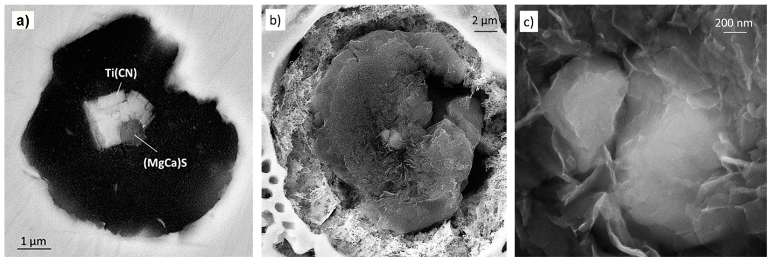
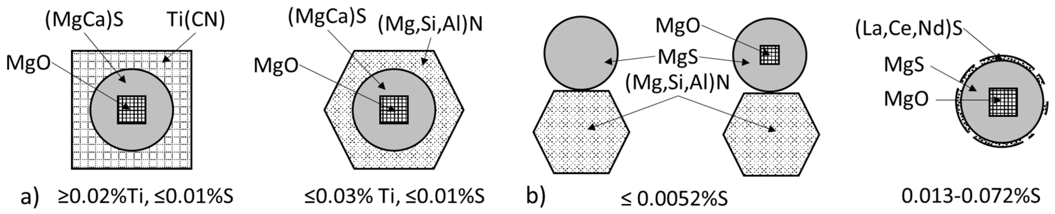
3.7. Influence of Base Metal Composition on the Nature of Nuclei

Nakae and Igarashi [102] found that sulfur content in Mg-treated iron (0.0004–0.059% S, 0.018–0.045% Mg) has a significant effect on the nature of the SG nuclei. Indeed, at S content above 0.005%, the nucleus is a spherical MgS, while at S contents less than 0.0022% the nucleus is a hexagonal (Mg,Si,Al)N, as shown in Figure 20. The maximum number of graphite nodules was found for the SG iron prepared from the 0.01%S base iron (Figure 21).
Alonso et al. [106] investigated the effect of titanium on SG nucleation in melts with 0.038–0.056% Mg, 0.006–0.01% S and 0.007–0.037% Ti, with and without inoculation on samples quenched during solidification. SEM/EDX examination of images allowed estimation of the type of compounds. As seen in Figure 22a, the Ti level in the base melt significantly affects the type of inclusions that act as nuclei for SG. For irons with less than 0.01%Ti the dominant inclusions are (Mg,Si,Al)N and the sulfides, while for the high Ti irons the Ti(CN) and sulfides are the most frequent. In many instances, the nucleus was made of two or three different compounds, and all of them were in contact with the graphite. The nitrides grow on complex Mg-Ca or Mg-Ca-La sulfides that can nucleate on Mg oxides or oxysulfides (Figure 23). As the Ti level increases, the number of oxides decreases fast. The cubic morphology of the TiC is seen in Figure 24a,b and the hexagonal crystal morphology of the Mg-Si-Al nitride in Figure 24c.
In summary, in most cases, sequential nucleation in two- or three-stages was observed. The Ti content in the iron affected the sequential growth of the nuclei. Independently of the inoculant, the nucleus contained multiple compounds that nucleated on one another in sequences as follows:
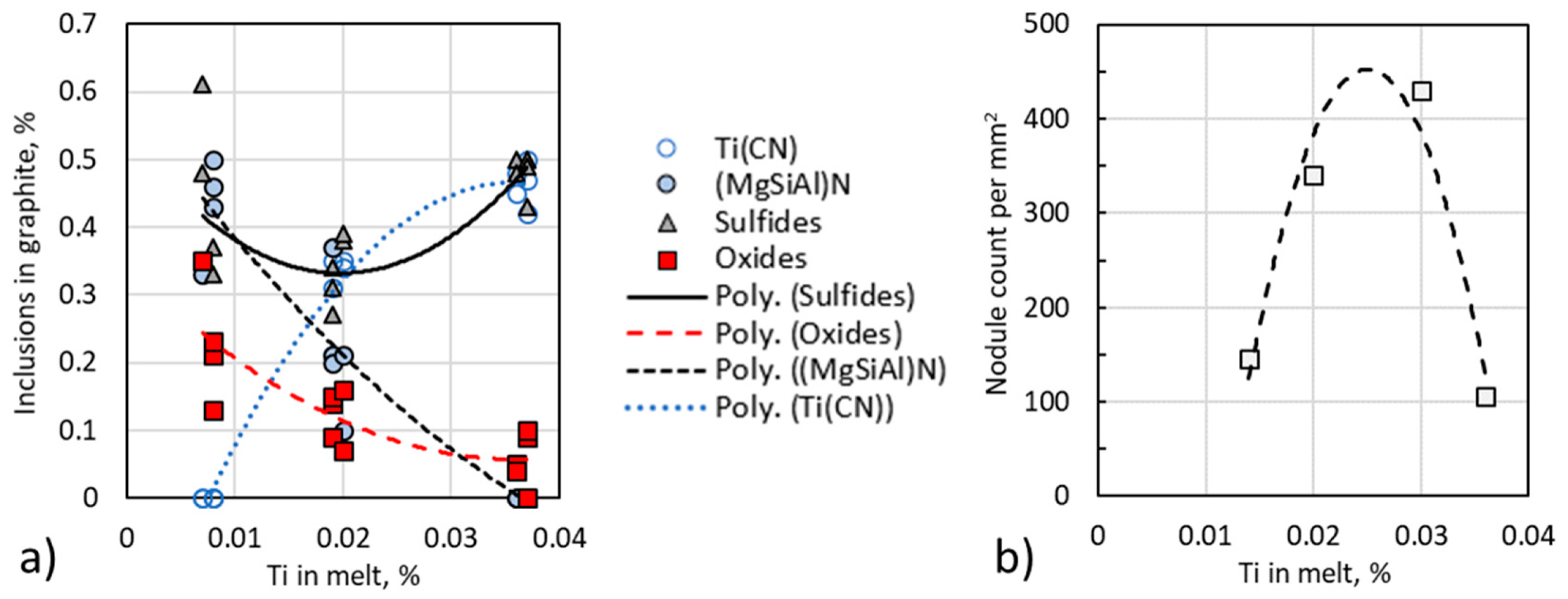
  • Ti ≤ 0.011%:  MgO→(MgCa)S or MgO→(MgCa)S→(Mg,Si,Al)N
  • Ti = 0.014%:  MgO→(MgCa)(OS) or (MgCa)S→(Mg,Si,Al)N
  • 0.02% ≤ Ti ≤ 0.03%: (MgCa)S or (MgCa)(OS)→Ti(CN) or/and (Mg,Si,Al)N
  • Ti = 0.036%:  (MgCa)S or (MgCa)(OS)→Ti(CN)
Not surprisingly, the influence of titanium on the nucleation sequence and the type of nuclei has a remarkable effect on the nodule count in ductile iron. As seen in Figure 22b, the highest nodule count occurs at Ti levels of 0.02–0.03%, which corresponds to the range where the best balance of oxides, sulfides and nitrides is achieved. Low Ti level produces high amounts of (Mg,Si,Al)N, while high levels of Ti generates high amounts of Ti (CN), both detrimental to the nodule count.
While inoculation increases the number of graphite nodules, no significant difference in the type of inclusions found in inoculated and not-inoculated samples was observed [106]. A Ce-containing inoculant was most effective in increasing the nodule count in low-Ti irons, while a ZrMn inoculant produced better results for high-Ti iron. The Al-rich inoculant appears to stimulate (Mg,Si,Al)N formation. Graphite in samples inoculated with a RE-rich inoculant exhibited some Ce and La sulfides in their nuclei, but such sulfides were also found in not-inoculated samples and can be attributed to the nodulizing agent.

3.8. Effect of the Shape of the Nucleus on Graphite Shape

For homogeneous nucleation, the shape of the final crystal does not depend on the shape of the nucleus as they have the same crystallography. In heterogenous, nucleation the situation is more complex, as multiple inclusions of various compositions may form the nucleus. However, recent work by Pugliara et al. [108] consisting of 3D-STEM observation of one multiphase nucleus of spheroidal graphite, claimed to have provided “a definitive proof that the shape of a nucleus does not determine that of the emerging graphite precipitate”, as the elongated nucleus produced a good spheroid. Our observations on hundreds of nuclei show that, indeed, when graphite crystallization occurs on sulfides or oxides the shape of the graphite nodule is most often close to spherical. This is not necessarily true when the nuclei are nitrides. When the nucleus is spherical as is often the case for sulfide inclusions, the platelets in the vicinity of the nucleus are less disorganized as compared with those adjacent to cuboidal or prismatic nuclei [104].
Consider the picture in Figure 25a. The Ti-Zr carbonitride that has grown around an MgO inclusion clearly affects graphite growth, producing an aggregate which appears to show a smaller spheroid on the carbonitride side attached to a larger spheroid on the Mg sulfide side. This is because graphite growth is more favored by the crystallography of the sulfide compared with that of the carbonitride. The spheroid in Figure 25b,c has grown on a complex nucleus made of a sulfide (the black hole remained after sulfide dissolution after deep etching), an Mg oxide and a Ti carbonitride. Graphite growth was inhibited on the Ti(CN) side compared with that on the MgS side. This is in line with the report of He et al. [109] who stated that in annealed steel, the graphite spheroids nucleated on AlN are less regular than those produced from the direct decomposition of carbides.
It must be stated though that the growth time of the graphite may improve the overall shape, as recrystallization will favor a spheroidal one. It is also important to notice that initial growth of graphite on nitrides, such as the one shown in Figure 17c occurs through rather erratic platelets, which explains the lower crystallinity in the central zone of spheroids reported by many investigators.
There is an apparent discrepancy between Skaland et al. [86] silicate theory (Figure 19), which proposes an epitaxial growth mechanism of graphite on complex oxides (silicates) with an (MgCa)S core, and many other experimental data, e.g., [50,92,105] that found the nuclei to be Mg or MgCa sulfides with an MgO core or attachment. According to Nakae and Igarashi [102], this is because Skaland used a base melt with very low sulfur (e.g., 0.0036%S) as calculated from the composition of their raw materials.
The effect of the S and Ti level in the melt on the nucleation mechanism of SG is summarized in Figure 26 based on the experimental work reported in References [102,106]. It is seen that in low-sulfur irons (≤0.01%), nitrides play an important role. The type of nitride is a function of the Ti level in the iron, with Ti(CN) being dominant at ≥0.02%Ti, and (Mg,Si,Al)N at the smaller Ti contents. Sequential nucleation oxide→sulfide→nitride is most common. At the sulfur level in excess of 0.013%, the Mg sulfide with an oxide core is most frequent. Lanthanides and cerium sulfides may partially cover the round MgS which explain their efficiency when present in the Mg treatment alloy or in the inoculant.
We should note that earlier secondary ion mass spectroscopy analysis on duplex graphite nodules by Franklin and Stark [110] support nitride nucleation at higher Ti levels in the iron, as Ti concentration is seen in the position of the nucleus, suggesting a Ti-based inclusion (Figure 27b). However, the rather uniform distribution of La and Ce across the core but not the shell in an iron treated with Ce-mischmetal (Figure 27a) implies no nucleation effect, but continuous incorporation in the Gr growing in the liquid. Mg, Ca, and Ti exhibited a peak outside of the nodule, indicating the presence of an inclusion. Other than that, Mg was uniformly distributed throughout the graphite and the matrix, which is not confirmed by more recent research.

4. Nucleation of Graphite during Solid-State Transformation

To help understanding solid-state nucleation of graphite irons of ~4.35% carbon equivalent (%C+0.31 %Si-0027·%Mn) with Mg levels of <0.01 to 0.047% were rapidly solidified in copper molds to produce 4 mm thick disks with metastable ledeburite structure [111]. The samples were then annealed at 950 °C to promote graphite growth, and then quenched in water. For all samples, the graphite count increases with the annealing time, which implies that significant nucleation occurred in a solid state. The number of graphite aggregates also increased with higher Mg, demonstrating that Mg plays an important role in solid-state nucleation. Thus, both nucleation in the liquid, observable on the as-cast quenched samples, and nucleation in the solid, observable in the annealed sample, must be considered.
In the absence of Mg, nucleation occurs on the pre-existing iron carbide plates (Figure 28a). However, in a limited number of cases, sequential nucleation on MgO→MgS was observed on residual oxides/sulfides coming from the charge materials that included SG iron returns (Figure 28b,c). Additions as low as 0.017% Mg induced significant nucleation in the liquid with the formation of new Mg or complex Mg sulfide and oxide inclusions, on which most nucleation occurred during subsequent annealing.

5. Growth of Graphite during Solidification

Industrial cast irons exhibit a large variety of graphite morphologies, including the “standard” shapes: Lamellar or flake (LG), compacted or vermicular (CG), spheroidal or nodular (SG), and temper or aggregated graphite (in malleable iron), as well as some “degenerated” morphology, such as spiky, exploded, or chunky graphite. The reasons for this wide variation in shape and crystallography reside in the chemical complexity of the iron melts, and the transitory nature of nucleation, local segregation and cooling rate during solidification. Room temperature graphite morphology in cast Fe-C alloys is the result of crystallization from the liquid, initially controlled by attachment kinetics, and then by crystallization and growth in the austenite (γ), pearlite or ferrite, controlled by carbon diffusion.

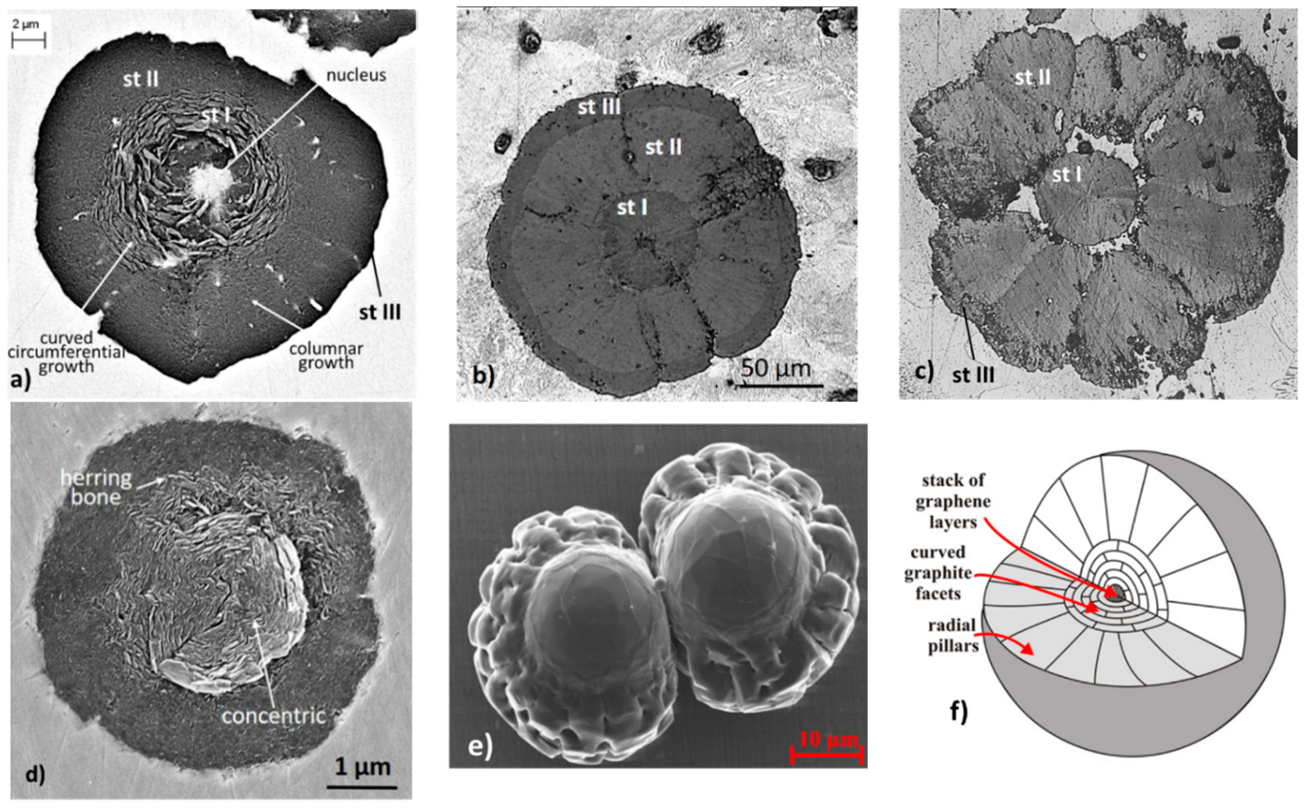
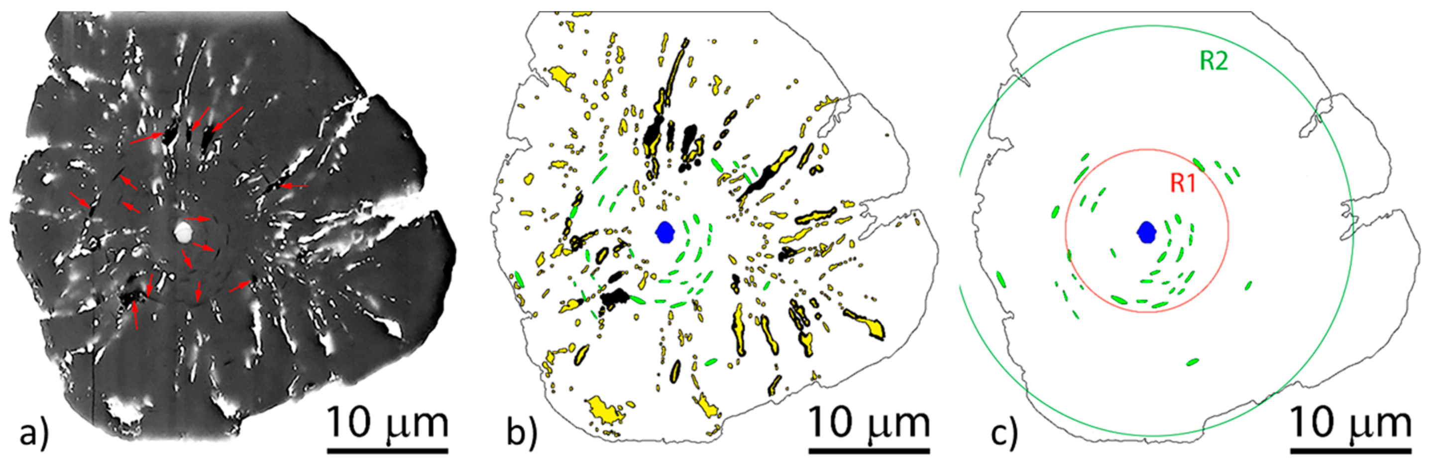
5.1. Growth of Spheroidal Graphite

Understanding the complexity graphite crystallization from iron melts is not trivial, and comparative studies of crystal growth in materials with crystal morphologies analogous to that of graphite are helpful. Similarities between the solidification of Si- and Ge-based eutectics and cast irons were discussed by Hellawell [112]. Loper et al. [113] turned their attention to analogies between Al-Si alloys and cast iron. Stefanescu et al. [12] included in their analysis growth of other hexagonal or tetragonal crystals, such as ice crystals and Al3Ti in aluminum-titanium alloys, as well as growth of graphite through other processing routes, such as chemical vapor deposition (a gas-to-solid transformation), and heat treatment of carbon steel (a solid-to-solid transformation). All this information provides a solid basis for a better understanding of graphite crystallization.
Early investigators sought to explain the various graphite morphologies encountered in castings through the interplay between the growth velocity of the basal face (0001) and the prism face ( 10 1 ¯ 0 ) of the graphite crystal. For equilibrium conditions, the Gibbs-Curie-Wulf law states that the crystal face in contact with the melt that has the highest interface energy grows more rapidly in the normal direction. Estimated data suggested that for graphite the ratio between the interface energies of the planes is γ [ 10 1 ¯ 0 ] / γ [ 0001 ] = 7.7 . Thus, the preferred growth direction should be the a-direction [ 10 1 ¯ 0 ] . Bravais’ rule stipulates that the growth rate in the direction normal to a plane is inversely proportional to the density of atoms located on the plane which again means that the preferred growth direction should be the a-direction. However, for non-equilibrium conditions, directional solidification studies of pure metals concluded that the most densely occupied crystal face has the highest growth velocity in the direction of its normal [114,115]. Based on this information Herfurth [116] argued that assuming growth by two-dimensional (2-D) nucleation, the highest rate of growth will be on the face with the higher density of atoms, where the probability for nucleation is higher. Thus, in a melt with surface-active impurities (S, O, Pb, Ti, etc.), these elements are adsorbed on the high-energy plane [ 10 1 ¯ 0 ] , which then have higher atomic density than the [0001] faces, and growth is predominant in the a-direction with formation of lamellar (plate) graphite (Figure 29a). When reactive impurities (Mg, Ce, La) are added to the melt, they remove the surface-active elements, and the preferred growth direction becomes the c-direction, and polycrystalline spheroidal graphite results (Figure 29b). In pure Fe-C-Si alloys, the highest growth rate will also be in the c-direction [0001] of the graphite crystal.
Similar conclusions were reached by McSwain and Bates [53] who, based on sessile drop experiments, found that graphite grows from the melt normal to the plane with the lowest interfacial energy, which is the c-direction [0001] for a Fe-C-Mg alloy and the a-direction [1010] for a Fe-C-S alloy (see Table 1).
In their early theory of defect growth of graphite, Minkoff and Lux [36] argue that growth occurs from steps on the graphite layers related to such defects as unmatching boundaries, twisted boundaries, and screw dislocations, with the associated growth mechanisms: 2-D nucleation, step at twisted boundary (rotational stacking fault of angles 13°, 22° or 28°), and spiral growth of screw dislocations, respectively (Figure 8). The first two mechanisms are governed by exponential laws and apply to the ( 10 1 ¯ 0 ) surfaces of graphite. The third is governed by a parabolic law and applies to the (0001) surface. When weak surface-active impurities, such as sulfur are present in the melt, the edge energy of steps change, resulting in relative position change of the growth rates involved, as shown in Figure 30a. The curve for growth on the step of a defect boundary, V s t e p , is at a lower undercooling than those for growth by 2-D nucleation, V 2 D , or by screw dislocation, V s c r e w . Thus, defect boundary growth is dominant. In a pure melt, the growth velocity curves are displaced to higher undercooling (Figure 30b). In a pure melt, or when increasing cooling rate, the higher degree of undercooling may allow growth through screw dislocations, so that graphite spheroids can form. Indeed, the LG-to-SG transition was obtained in pure Ni-C alloys by increasing the cooling rate, and in ultrapure Fe-C alloys by cooling slowly in a vacuum. Impurities will react with the surface-active elements and the growth on twist boundary will be neutralized, leaving only the curves for V 2 D and V s c r e w displaced to greater undercooling (Figure 30c).
In more recent work on high purity Ni-C alloys, Amini and Abbaschian [31] argued that as the driving force (undercooling, supersaturation) for solidification increases, a roughening transition from faceted to diffuse G/L interface occurs, producing a change in the growth mechanism from 2-D faceted (limited by carbon diffusion to the interface) to linear continuous that brings about the LG-to-SG transition. In the range of continuous growth, isotropic growth of graphite occurs, as the growth velocities in the 10 1 ¯ 0 and 0001 directions are very close. This produces graphite spheroids. Amini and Abbaschian also calculated that thickening of the graphite plates can be described by 2D nucleation and growth in its poly-nucleation growth (PNG) variant.
Theuwissen et al. [117] argue that the 2-D PNG nucleation mechanism advocated by Amini and Abbaschian for polyhedral plates is operational for both flake and spheroidal graphite. As there is no direct experimental evidence to support this contention, Lacaze et al. [118] attempted to support it through analytical calculations. The lateral extension of the new graphite layers controlled by carbon diffusion in the liquid was assumed. The model calculations are summarized in Figure 31. The choice of calculation range for undercooling up to 250 K is surprising, as undercoolings higher than about 50 K will be conducive to metastable structure in Fe-C-Si alloys. We also notice some numerical incongruities: At a reasonable undercooling of 25 K (thin vertical line on the figure) it will take 3 hrs. For the formation of a 1 µm graphite spheroid for the 0.1 diffuseness curve, and 1.4 × 10⁸ h. for 0.5 diffuseness. The growth rate goes to zero at about 15 K undercooling. Such unrealistic calculation results are not surprising given the number of parameters that have to be estimated (e.g., the height of the nucleating disk, diffuseness, the correction for the structural factors), and demonstrate that analytical models cannot describe the complexities associated with SG crystallization. Fortunately, contemporary researchers have other tools available in their arsenal and results with such tools will be discussed in the following paragraphs.
Capitalizing on his successful work on aluminum alloys, Campbell [14,120] emphasizes the role of oxide double films (silica bifilms) on the growth of various forms of graphite. The presence of oxides (MgO, SiO2, Fe2O3, MnO) or silicates (Mg2SiO4, Fe2SiO4) in liquid ductile iron or in the associated slag is well documented through experiments, e.g., [70,121], and through thermodynamic calculations, e.g., [122]. Campbell argues that these oxides are not compact spheres, cubes, rods, etc., but rather films or bifilms that have lower Stokes velocity, which allows them to remain in suspension in the melt for long periods of time. In the absence of Mg, oxysulfide particles nucleate on silica-rich oxide bifilms, followed by nucleation and growth of graphite on the oxysulfide inclusions to produce lamellar graphite. Magnesium additions eliminate the silica-rich bifilms, and then, graphite spheroids grow on the oxysulfides, as the spherical shape is assumed to be the natural growth mode of graphite. Degenerated graphite forms could also be explained through this mechanism. It is unclear how sulfur affects graphite shape.
It is now accepted that the graphite spheroid is, in most cases, the product of several growth stages, starting with curved circumferential growth in contact with the liquid (stage I), followed by columnar-layer growth through an austenite shell during the eutectic reaction (stage II). Further growth occurs during the solid-solid transformation as the solubility of carbon in austenite, and then ferrite, decreases with temperature (stage III). Multiple examples are available. Selected ones are shown in Figure 32. However, in many instances, graphite spheroids with only two or one stages are found. We now turn to the difficult task to explain these complex aggregates.
At low undercooling and supersaturation graphite grows in the general a-direction as large plates made of hexagonal faceted platelets distributed in a tiled-roof configuration. The platelets twin and branch as they grow, generating lamellar graphite (Figure 9). As the driving force increases, graphite platelets begin stacking in the c-direction forming foliated dendrites (Figure 10). Upon further increase in undercooling and supersaturation following additions of graphite compacting elements (e.g., Mg, Ce) or higher cooling rate, foliated graphite platelets stack increasingly along the c-direction, producing polyhedral blocks (Figure 11) and highly curved graphite aggregates branching in various directions [30].
Regarding crystallization of graphite spheroids, the mechanism for early stages of solidification (stage-I), appears to be consistently explained by the curved-circumferential crystal growth mechanism postulated by Sadocha and Gruzleski (Figure 14a). It is supported by direct observations, such as micrographs obtained through plasma etching (Figure 14b) or through chemical etching on Fe-C-Si alloys (Figure 32a–d) and of Ni-C alloys (Figure 14c and Figure 32e). Thermal etching [123] also allowed observation of significant defects in the circumferential growth region, with plate-graphite in the center, and voids between the curved graphite plates. The high resolution focused ion beam (FIB) 3D tomography using a plasma source [124] indirectly confirmed the existence of two stages through the observation of concentric voids in the central region (circumferential growth) and radially oriented voids in the outside region (sector growth) (Figure 33). TEM work [20] also found that curved basal planes accommodate the curvature of spheroidal graphite growing in the liquid.
However, the curved platelets are not always in direct contact along the (0001) planes as observable in Figure 14c where the peripheral platelets are separated from the platelets under them. Thus, a curved-circumferential foliated dendrite growth can also be envisioned.
For stage II of SG growth, the images in Figure 32 suggest a radial growth of cylindrical columns or of conical sectors, similar to the pyramidal sectors found in ice and silicon crystals. The cone-helix model postulated by Double and Hellawell [34,125], based on positive wedge disclination, is probably the best-reasoned model to explain this type of growth. When subtracting a wedge from the basic hexagon, the graphene sheet can curl around itself at an angle α = 60 ° (but not only) to produce a cone [45,47]. This model (Figure 34a) may explain the herring-bone appearance of graphite platelets in some spheroids (Figure 32d) and is also consistent with the observation that the growing ends of whiskers produced through carbon pyrolysis assumed a conical shape [126].
Questions on the operation of the cone-helix model at the scale of a graphite spheroid arise from recent TEM work [109,127] that show that the [0001] direction of graphite planes is parallel to the symmetry axis of the cone in the graphite spheroid. However, the cone-helix model generates {0001} graphite planes rotated around the cone symmetry axis that is at an angle with respect to the axis of the cone. This apparent discrepancy can be explained through the effect of the sectioning of the TEM sample at different angles [125].
A similar mechanism was proposed by Miao et al. [29] and endorsed by He et al. [109]. It was found that the [001] direction of each platelet is twisted about 2° around the radius of the graphite spherulite and the 001 directions of all platelets are oriented nearly parallel to the radius, suggesting that the graphite has grown in a spiral manner from a common nucleus. The difference between The Miao et al. model (Figure 34b) and the cone-helix growth mechanism is that the former assumes growth in the c-direction through spiral growth, while the latter postulates growth in the a-direction of platelets.
Neither the curved circumferential growth, nor the con-helix mode can explain the growth of cylindrical columns observed in ice crystals, Al-Si alloys, metamorphic graphite (Figure 35), Ni-C alloys (Figure 32e), and in Fe-C-Si alloys [12]. Experiments [42] have shown that at sufficient Mg levels, the platelets aggregate in clusters that produce blocks of polyhedral graphite, similar to those found in natural graphite. Apparent nucleation of new crystals found on polyhedral ice plates and on metamorphic graphite (Figure 35b) may point to the possibility that PNG (Figure 7b) may explain the growth of such shapes. Alternatively, as the platelets of the column present clear separations, they could be the result of foliated crystal stacking through foliated growth (Figure 11). The twist-tilt boundary mechanism (Figure 8) suggested by Frank [35] can also explain the growth in the c-direction as small angle tilt or twist boundaries between adjacent grains of graphite provide nucleation sites for growth along the c-axis. Some evidence for this growth mechanism can be seen from the arrangement of steps on the pinacoid surfaces in Figure 35a.
The decreased carbon solubility in the austenite with lower temperature produce carbon atoms migration to the growing graphite, which is the reason for stage-III graphite growth. However, high diffusion rates may result in recrystallization of carbon, and thus, in the morphing of stage-III microstructure into the conical sector structure of stage-II [107]. Examples of crystallization of amorphous carbon to form spheroids are also found for processes unrelated to metal casting, such as heating of amorphous carbon in an electronic beam [128]. Crystallization of the amorphous carbon can occur at all stages of solidification. It may thicken the existing platelets or grow new platelets. It may fill the spaces between the columnar crystals or not [107].
In summary, this analysis demonstrates that in Mg-treated irons graphite growth takes place through a multitude of mechanisms as a function of the local conditions at the solidifying interface as affected by undercooling and supersaturation. Schematic representations of the effect of processing variables on graphite growth, like the one in Figure 36, have been proposed by many investigators over time [47,129,130]. They can give a general idea of the transitions from lamellar to spheroidal graphite, but they cannot capture the complexity of the associated phenomena.

5.2. Growth of Degenerated Graphite

Figure 32c shows clearly separated conical graphite columns that indicate the beginning of graphite degeneration. There are many forms of so-called degenerated graphite, including dendritic, exploded, chunky, and spiky. They all have damaging effects on the mechanical properties of the iron, as summarized in an excellent review for chunky graphite (CHG) by Baer [13].
Dendritic graphite in LG iron has been observed and discussed by Oron and Minkoff [38]. Its growth was associated with twist boundary defects. Graphite dendrites were also observed in Sb containing CG irons (Figure 37a) and in slow-cooling cerium treated SG irons (Figure 37b). However, unlike the common stem-dendrites found LG iron that grows along the a-direction, the dendrites in Mg or Ce-treated irons are stacked in the c-direction (Figure 37c).
There are some clear similarities between graphite dendrites and chunky graphite. Like CG, chunky graphite is interconnected, and in many instances, grows radially from a common center (Figure 38a). The interconnected structure of the chunky graphite has been documented by various investigators [130,132,133].
The schematic representation of the sequence of graphite degeneration from SG to CHG presented in Figure 39 captures two important elements of the morphology of CHG, the radial growth and the interconnection of various segments. Interconnection is always seen, but radial growth is not always present. An apparently different form of degenerated graphite appears as concatenated (chain-linked) small graphite spheres [135] observed in Si solution-strengthened SG iron (Figure 38). However, after analyzing other research on Si solution-strengthened SG iron [136], Baer [131] concluded that chunky graphite in these materials exhibits the same microstructural features as typical for conventional ferritic SG irons.
TEM images of dendritic graphite show that the aggregate is made of graphite layers stacked in the c-direction (Figure 37c), and so is CHG. Ultrasonic vibration breaking of CHG aggregates by Itofuji et al. [132] produced blocks with hexagonal shape made of parallel graphite platelets (their Figure 7). They concluded that CHG was built of graphite blocks, that no spiral growth was involved in the process, and that the basic substructure of CG, SG and CHG is the same, implying that they grow through the same mechanism. However, the helical growth of chunky graphite has been documented by Liu et al. [48] through the SEM image in Figure 13. Additional evidence was provided by Gagné and Argo [137] from deep etched chunky graphite samples, and by Labrecque et al. [138] through the examination of broken chunky graphite. Other possible growth mechanisms include foliated dendrite growth (Figure 10) and foliated columnar growth (Figure 11).
From this discussion, it is apparent that understanding crystallization of chunky graphite is still a work in progress. Nevertheless, how about controlling this defect in castings? It is well known that the chemical composition and the solidification rate affect the occurrence of CHG. The widely quoted Thielemann equation [139] could be used to assess the complex effect of relevant trace elements on graphite formation in irons modified with Mg alloys:
S b = 4.4   w T i + 2   w A s + 2.3   w S n + 5   w S b + 290   w P b + 370   w B i + 1.6   w A l
where w i stands for the content of the element i in wt%. To avoid graphite degeneration in the production of SG iron it is suggested to have S b > 1 . If this level is exceeded, rare earth additions are recommended. The practical applicability of this equation is limited by the fact that it does not include the effect of solidification time.
Another equation proposed by Löblich [140] considers the influence of Ce, Pb, Sb and As on the maximum tolerable Si content for CHG avoidance:
w S i = [ 2.26 1.5 ( w C e w P b + w S b + w A s ) ] / [ 1 0.64 ( w C e w P b + w S b + w A s ) ]
The equation is valid for a wall thickness of 200 mm. The tolerance is higher as the wall thickness decreases as indicated by the arrow in Figure 40. Further research [141] demonstrated that the Si criterion works for melts containing the elements included in the previous equation, but fails when other elements, such as Al, Ca, B and Bi are present, and proposed another empirical parameter, including more elements and the modulus (Figure 41). Below an element ratio of about 45 and a thermal modulus ≤ 4.2 cm, no chunky graphite is formed (range 1).
Baer’s review includes other similar criteria, including one by Sertucha et al. [142]. However, according to Baer, quantitative rules to prevent chunky graphite are complex and have limited practical impact because of the exceedingly narrow validity windows. Because of the controversial aspect of many publications and the big scatter of the literature data, no specific numbers could be recommended for chemical element contents, temperatures, and other process parameters. Nevertheless, it was concluded that the most relevant measures reported to be effective against CHG formation include increased cooling rate, reduction of the silicon content, control of trace elements and addition of specific alloying elements.

6. Solid-State Growth of Graphite

When discussing growth of graphite in solid state one must take into account the growth environment, whether Mg-free liquid (e.g., steel) or not, and also differentiate between the growth of graphite crystallized in the liquid and then cooled to room temperature, and that of graphite nucleated in the liquid, but grown during subsequent heat treatment, such as annealing or austempering. The type of nuclei on which this graphite grows appears to be important.
Work by Cowlam et al. [143] on ferritic steels reveled that the crystallinity of graphite increased and the c-spacing of the lattice parameter decreased with increased annealing times. This again demonstrated recrystallization of graphite upon residence at elevated temperature.
In their study of the graphitization annealing of 0.38 wt.% carbon steel in the quenched martensitic state, He et al. [109] found that some nodules exhibited an irregular morphology with a nitride or an oxide core, while others were more regularly spheroidal and without a nucleating particle. TEM microscopy demonstrated that for the more spherical nodules, the outer mantles had a strong graphitic character, while the core regions exhibited a more amorphous carbon structure. They also concluded that most nucleation was provided by the dissolving cementite particles in the martensite.
In Mg-treated irons graphite nucleation may be expected to occur in the liquid. Upon subsequent cooling graphite growth may be significant as in typical ductile iron where some solid-state growth occurs because of decreased carbon solubility in the cooling austenite, or extremely limited as in low carbon equivalent rapidly cooled irons (malleable iron), where graphite growth is achieved in additional processing through heat treatment.
Some unusual alternative to the above scenario is SG growth in irons solidified partly in the stable system and partly in the metastable one. Laffont et al. [144] studied such a material and confirmed the two-fold structure (well-crystallized outer zone and distorted inner zone.) of nodules in as-cast material as discussed previously in this paper. The inner zone of the graphite recrystallized during heat-treatment producing a radial sectors structure, visible at room temperature. Then, assuming that formation of this zone in the as-cast material is the result of mechanical deformation because of liquid contraction during metastable solidification, they conclude that the growth mechanism of SG “could be the same when nodules precipitate directly from the liquid during solidification or precipitate by cementite decomposition during solid-state heat-treatment in the austenitic field”. However, as shown extensively in this paper, the two-fold structure of SG is typical for as-cast ductile iron and does not incur upon metastable solidification. Furthermore, as we will show in the following paragraphs, a completely different graphite structure is obtained for graphite produced through the decomposition of cementite in Mg-treated irons.
Evans [145] suggested the addition of Mg to malleable iron to increase the number of graphite particles and decrease the duration of the heat treatment. To further understand solid-state graphite growth in metastable solidified Mg-treated melts, irons with Mg ranging from <0.01 to 0.047% were rapidly solidified in small discs and then annealed at 950 °C [111]. It was confirmed that in the Mg-free iron nucleation occurs on the iron carbide plates (Figure 28a). However, even at low Mg level of 0.017% nucleation occurs on Mg sulfide and oxide inclusions (Figure 28b).
In Mg-free annealed iron, the graphite appears as an irregular cluster of plates and blocks growing outward from a common center (Figure 42a). The iron with 0.017% Mg exhibited graphite with the appearance of complex quasispheroidal skeletal-hopper crystals with multiple empty hexagonal cavities (Figure 42b). At 0.047% Mg, the graphite morphology included hemispherical (Figure 42c), incomplete spheroids, and hopper crystals with a much lower number of empty cavities, as graphite growth is constrained by the adjacent carbide plates. The curved plates observed on the surface of the quasispheroidal and hemispherical graphite appear to indicate that curved circumferential growth mechanism is active not only in the liquid, but also during solid state growth.
Two different mechanisms could explain the formation of skeletal-hopper crystals in the Fe-C Mg-treated alloys. Because of high carbon supersaturation of the eutectic austenite resulting from the decomposition of carbides, the crystal edges and corners grow faster than the faces producing the holes in the growing graphite aggregate (Figure 15). Alternatively, Mg atoms may block the step-growth of dislocations, as suggested by Minkoff and Nixon [146].
The hemispherical growth of graphite at high Mg levels starts with graphite nucleation on Mg sulfide or oxide inclusions entrapped at the Fe3C/γ interface during eutectic solidification (Figure 43a). Initial growth occurs from the decomposition of the carbides in direct contact with the graphite (Figure 43b). High cooling rate and the crystallography of the MgS inclusion produce curved hemispherical graphite. Once an austenite layer separates the graphite and the carbide growth occurs mostly through carbon diffusion through the austenite. A schematic representation of the process is presented in Figure 44.
This analysis demonstrates that the mechanism of graphite growth in solid-state appears to be much more complex than originally discussed in previous literature.

7. Conclusions

The body of evidence reviewed in this work is conducive to a number of conclusions. Nucleation of graphite spheroids during the solidification of Mg-treated irons occurs most of the time through sequential nucleation with the formation of complex nuclei composed of several inclusions. The most favorable nuclei for graphite shape and nodule counts are the Mg sulfide and oxide inclusions, many times found as oxysulfides that can include other elements, such as Ca, Ce, lanthanides, Ba and others. When graphite crystallization occurs on sulfides or oxides the shape of the graphite nodule is most often close to spherical. This is not always the case when the nuclei are nitrides. Titanium nitrides or carbonitrides and Mg-Al-Si nitrides affect both the graphite shape and the nodule count negatively. The type of nuclei produced by the liquid treatment (spheroidizing and inoculation) is controlled by the S and Ti level in the base metal. The most frequent sequence in complex nucleation of irons with Ti ≤ 0.014% is MgO→(MgCa)S→nitrides, while in irons with Ti ≥ 0.02% it is (MgCa)S or (MgCa)(OS)→nitride.
Nucleation of graphite in the solid state in Mg-free irons occurs on the iron carbides. However, even minute amounts of Mg, such as residual Mg from the charge materials, may generate sulfides which become nuclei during the solid-state graphitization.
In Mg-treated irons graphite growth occurs through a multitude of mechanisms as a function of the local conditions at the solidifying interface as affected by undercooling and supersaturation. The multi-mechanism growth of graphite involves layer growth through poly-nucleation and spiral dislocation, foliated crystals growth, curved-circumferential growth, helical (macro-spiral) and cone-helix (micro-spiral) growth, radial growth of cylindrical or conical sectors, and skeletal (hopper) crystal growth. These mechanisms explain the various morphologies of graphite in Mg-treated irons, including CG, SG, and CHG. Recrystallization plays an important role in the final graphite shape, both during the eutectic and solid-state transformation.

Author Contributions

Conceptualization, D.M.S. and R.S.; methodology, D.M.S. and G.A.; formal analysis, D.M.S., G.A., R.S.; investigation, G.A., D.M.S.; writing—original draft preparation, D.M.S.; writing—review and editing, D.M.S., G.A., R.S.; project administration, R.S. All authors have read and agree to the published version of the manuscript.

Funding

This research was funded by Diputacion Foral de Bizkaia y.

Conflicts of Interest

The authors declare no conflict of interest.

References

  1. Korsakov, A.V.; Rezvukhina, O.V.; Jaszczak, J.A.; Rezvukhin, D.I.; Mikhailenko, D.S. Natural Graphite Cuboids. Minerals 2019, 9, 110. [Google Scholar] [CrossRef] [Green Version]
  2. Adey, C. Verfahren zum Herstellen von Grauguss höherer Festigkeit. German Patent No. 766592, June 1953. [Google Scholar]
  3. Prucha, T.E.; Twarog, D.; Monroe, R.W. History and Trends of Metal Casting. In ASM Handbook, Vol. 15 Casting; ASM International: Metals Park, OH, USA, 2008; pp. 3–154. [Google Scholar]
  4. Stefanescu, D.M. The Meritocratic Ascendance of Cast Iron: From Magic to Virtual Cast Iron. Int. J. Metalcasting 2019, 13, 726–752. [Google Scholar] [CrossRef]
  5. Wind turbine casting market analysis by type (horizontal axis, vertical axis), by application (onshore, offshore), by region (north America, Europe, Asia Pacific, central & South America, MEA), and segment forecasts, 2018–2025, Grand View Research Report, San Francisco, CA, USA (Jan, 2017). Available online: https://www.grandviewresearch.com/industry-analysis/wind-turbine-casting-market (accessed on 4 February 2020).
  6. Merchant, H.D. Solidification of Cast Iron—A Review of Literature. In Recent Research in Cast Iron; Merchant, H.D., Ed.; Gordon and Breach Sci. Publ.: New York, NY, USA, 1968. [Google Scholar]
  7. Minkoff, I. The Physical Metallurgy of Cast Iron; John Wiley & Sons: New York, NY, USA, 1983. [Google Scholar]
  8. Elliott, R. Cast Iron Technology; Butterworths: London, UK, 1988. [Google Scholar]
  9. Stefanescu, D.M. Microstructure Evolution during the Liquid/Solid Transformation in Cast Iron. In ASM Handbook Vol. 1A Cast Iron Science and Technology; Stefanescu, D.M., Ed.; ASM International: Materials Park, OH, USA, 2017; pp. 59–80. [Google Scholar]
  10. Skaland, T. Spheroidal Graphite Nuclei in Rare Earth and Magnesium Inoculated Irons. In Proceedings of the AFS Cast Iron Inoculation Conference, Schaumburg, IL, USA, 29–30 September 2005; pp. 13–30. [Google Scholar]
  11. Riposan, I.; Skaland, T. Modification and Inoculation of Cast Iron. In ASM Handbook Vol. 1A Cast Iron Science and Technology; Stefanescu, D.M., Ed.; ASM International: Materials Park, OH, USA, 2017; pp. 160–176. [Google Scholar]
  12. Stefanescu, D.M.; Alonso, G.; Larrañaga, P.; De la Fuente, E.; Suarez, R. A comparative study of graphite growth in cast iron and in analogous systems. Int. J. Metalcasting 2018, 12, 722–752. [Google Scholar] [CrossRef]
  13. Baer, W. Chunky Graphite in Ferritic Spheroidal Graphite Cast Iron: Formation, Prevention, Characterization, Impact on Properties: An Overview. Int. J. Metalcasting 2019. [Google Scholar] [CrossRef] [Green Version]
  14. Campbell, J. A Hypothesis for Cast Iron Microstructures. Metall. Mater. Trans. B 2009, 40, 786–801. [Google Scholar] [CrossRef]
  15. Zhou, X.F.; Qian, G.R.; Dong, X.; Zhang, L.; Tian, Y.; Wang, H.T. Ab initio study of the formation of transparent carbon under pressure. Phys. Rev. B 2010, 82, 134126. [Google Scholar] [CrossRef] [Green Version]
  16. Castro Neto, A.H.; Guinea, F.; Peres, N.M.R. Drawing conclusions from Graphene. Phys. World 2006, 16, 11. [Google Scholar]
  17. Pierson, H.O. Handbook of Carbon, Graphite, Diamond and Fullerenes: Properties, Processing, and Applications; Noyes Publications: Park Ridge, NJ, USA, 1993. [Google Scholar]
  18. Inagaki, M. Advanced carbon materials. In Handbook of Advanced Ceramics, 2nd ed.; Elsevier: Amsterdam, The Netherlands, 2013. [Google Scholar]
  19. Roviglione, A.N.; Hermida, J.D. Rhombohedral Graphite Phase in Nodules from Ductile Cast Iron. Procedia Mater. Sci. 2015, 8, 924–933. [Google Scholar] [CrossRef] [Green Version]
  20. Qing, J.; Richards, V.L.; Van Aken, D.C. Growth stages and hexagonal-rhombohedral structural arrangements in spheroidal graphite observed in ductile iron. Carbon 2017, 116, 456–469. [Google Scholar] [CrossRef] [Green Version]
  21. Irifune, T.; Kurio, A.; Sakamoto, S.; Inoue, T.; Sumiya, H. Materials: Ultrahard polycrystalline diamond from graphite. Nature 2003, 421, 599–600. [Google Scholar] [CrossRef]
  22. Umemoto, K.; Wentzcovitch, R.M.; Saito, S.; Miyake, T. Body-Centered Tetragonal C4: A Viable sp3 Carbon Allotrope. Phys. Rev. Lett. 2010, 104, 125504. [Google Scholar] [CrossRef] [PubMed]
  23. Wyckoff, R.W.G. Crystal Structures; Interscience: New York, NY, USA, 1963. [Google Scholar]
  24. Kurz, W.; Fisher, D.J. Dendrite growth in eutectic alloys: The coupled zone. Int. Metals Rev. 1979, 24, 177–204. [Google Scholar]
  25. Burden, M.H.; Hunt, J.D. The extent of the eutectic range. J. Cryst. Growth 1974, 22, 328. [Google Scholar] [CrossRef]
  26. Stefanescu, D.M. Science and Engineering of Casting Solidification, 3rd ed.; Springer: Berlin, Germany, 2015. [Google Scholar]
  27. Lux, B.; Mollard, F.; Minkoff, I. On the formation of envelopes around graphite in cast iron. In The Metallurgy of Cast Iron; Lux, B., Minkoff, I., Mollard, F., Eds.; Georgi Publishing: St. Saphorin, Switzerland, 1975; pp. 371–403. [Google Scholar]
  28. Li, D.D.; Tan, R.X.; Gao, J.X.; Wei, B.Q.; Fan, Z.Q.; Huang, Q.Z.; He, K.J. Comparison of pyrolytic graphite spheres from propylene with spheroidal graphite nodules in steel. Carbon 2017, 111, 428–438. [Google Scholar] [CrossRef]
  29. Miao, B.; Northwood, D.O.; Bian, W.; Fang, K.; Fan, M. Structure and growth of platelets in graphite spherulites in cast iron. J. Mater. Sci. 1994, 29, 255–261. [Google Scholar] [CrossRef]
  30. Stefanescu, D.M.; Alonso, G.; Larrañaga, P.; De la Fuente, E.; Suarez, R. On the crystallization of graphite from liquid Iron-Carbon-Silicon melts. Acta Mater. 2016, 107, 102–126. [Google Scholar] [CrossRef]
  31. Amini, S.; Abbaschian, R. Nucleation and growth kinetics of graphene layers from a molten phase. Carbon 2013, 51, 110–123. [Google Scholar] [CrossRef]
  32. Lux, B.; Minkoff, I.; Mollard, F.; Thury, E. Branching of graphite crystals growing from a metallic solution. In The Metallurgy of Cast Iron; Lux, B., Minkoff, I., Mollard, F., Eds.; Georgi Publishing: St. Saphorin, Switzerland, 1975; pp. 496–508. [Google Scholar]
  33. Amini, S.; Kalaantari, H.; Mojgani, S.; Abbaschian, R. Graphite crystals grown within electromagnetically levitated metallic droplets. Acta Mater. 2012, 60, 7123–7131. [Google Scholar] [CrossRef]
  34. Double, D.D.; Hellawell, A. Growth structure of various forms of graphite. In The Metallurgy of Cast Iron; Lux, B., Minkoff, I., Mollard, F., Eds.; Georgi Publishing Co.: St Saphorin, Switzerland, 1975; pp. 509–528. [Google Scholar]
  35. Frank, F.C. The influence of dislocations on crystal growth. Disc. Faraday Soc. 1949, 5, 48–54. [Google Scholar] [CrossRef]
  36. Minkoff, I.; Lux, B. Graphite growth from metallic solution. In The Metallurgy of Cast Iron; Lux, B., Minkoff, I., Mollard, F., Eds.; Georgi Publishing: St. Saphorin, Switzerland, 1975; pp. 473–493. [Google Scholar]
  37. Hillert, M.; Lindblom, Y.J. The growth of nodular graphite. Iron Steel Inst. 1954, 148, 388. [Google Scholar]
  38. Oron, M.; Minkoff, I. Structural factors in growth of graphite from the melt. In Recent Research on Cast Iron; Merchant, H.D., Ed.; Gordon and Breach: New York, NY, USA, 1968; pp. 173–193. [Google Scholar]
  39. Delavignette, P.; Amelinckx, S. Dislocation patterns in graphite. J. Nucl. Mater. 1962, 5, 17–66. [Google Scholar] [CrossRef]
  40. Hennig, G.R. Screw Dislocations in Graphite. Science 1965, 147, 733–734. [Google Scholar] [CrossRef]
  41. Zakhartchenko, E.V.; Akimov, E.P.; Loper, C.R. Kish graphite in gray cast iron. Trans. Am. Foundry. Soc. 1979, 87, 471–476. [Google Scholar]
  42. Stefanescu, D.M.; Huff, R.; Alonso, G.; Larrañaga, P.; De la Fuente, E.; Suarez, R. On the crystallization of compacted and chunky graphite from liquid multicomponent iron–carbon–silicon based melts. Metall. Mater. Trans. 2016, 47, 4012–4023. [Google Scholar] [CrossRef]
  43. Saratovkin, D.D. Dendritic Crystallization; Consultants Bureau: New York, NY, USA, 1959. [Google Scholar]
  44. St. John, D.H.; Hogan, L.M. Metallography and growth crystallography of Al3Ti in Al-Ti alloys up to 5 wt% Ti. J. Cryst. Growth 1979, 46, 387–398. [Google Scholar] [CrossRef]
  45. Amelinckx, S.; Luyten, W.; Krekels, T.; Van Tendeloo, G.; Van Landuit, J. Conical, helically wound, graphite whiskers: A limiting member of the “fullerenes”? J. Cryst. Growth 1992, 121, 543–558. [Google Scholar] [CrossRef]
  46. Jaszczaka, J.A.; Robinson, G.W.; Dimovskic, S.; Gogotsic, Y. Naturally occurring graphite cones. Carbon 2003, 41, 2085–2092. [Google Scholar] [CrossRef]
  47. Kvasnitsa, V.N.; Yatsenko, V.G.; Jaszczak, J.A. Disclinations in unusual graphite crystals from anorthosites of Ukraine. Can. Mineral. 1999, 37, 951–960. [Google Scholar]
  48. Liu, P.C.; Li, C.L.; Wu, D.H.; Loper, C.R. SEM Study of Chunky Graphite in Heavy Section Ductile Iron. Trans. Am. Foundry. Soc. 1983, 91, 119–126. [Google Scholar]
  49. Sadocha, J.P.; Gruzleski, J.E. The mechanism of graphite spheroid formation pure Fe-C-Si alloys. In The Metallurgy of Cast Iron; Lux, B., Minkoff, I., Mollard, F., Eds.; Georgi Publishing: St. Saphorin, Switzerland, 1975; pp. 443–459. [Google Scholar]
  50. Lalich, M.J. The influence of Rare Earth elements on magnesium treated ductile cast iron. In The Metallurgy of Cast Iron; Lux, B., Minkoff, I., Mollard, F., Eds.; Georgi Publishing: St. Saphorin, Switzerland, 1974; pp. 561–581. [Google Scholar]
  51. Voigt, R. Trace (Minor) Elements in Cast Irons. In ASM Handbook Vol. 1A Cast Iron Science and Technology; Stefanescu, D.M., Ed.; ASM International: Materials Park, OH, USA, 2017; pp. 177–181. [Google Scholar]
  52. Vashchenko, K.I.; Rudoi, A.P. Surface tension of cast iron. Trans. Am. Foundry Soc. 1962, 70, 855–864. [Google Scholar]
  53. McSwain, R.H.; Bates, C.E. Surface and Interfacial Relationships Controlling Graphite Formation in Cast Iron. In The Metallurgy of Cast Iron; Lux, B., Minkoff, I., Mollard, F., Eds.; Georgi Publishing: St. Saphorin, Switzerland, 1975; pp. 423–442. [Google Scholar]
  54. Stefanescu, D.M.; Alonso, G.; Larrañaga, P.; Suarez, R. On the stable eutectic solidification of iron-carbon-silicon alloys. Acta Mater. 2016, 103, 103–114. [Google Scholar] [CrossRef]
  55. Turnbull, D.; Vonnegut, R. Nucleation Catalysis. Ind. Eng. Chem. 1952, 44, 1292–1298. [Google Scholar] [CrossRef]
  56. Bramfitt, B. The Effect of Carbide and Nitride Additions on the Heterogeneous Nucleation Behavior of Liquid Iron. Metall. Trans. 1970, 1, 1987–1995. [Google Scholar] [CrossRef]
  57. Geilenkirchen, T. Herstellung dichter Güsse durch desoxydierende Zuschläge. Stahl und Eisen 1908, 28, 592. [Google Scholar]
  58. Meehan, A.F. Making Gray Iron. U.S. Patent no. 1,499,068, 24 June 1924. [Google Scholar]
  59. Piwowarsky, E. German Patent no. 649,475, 2 November 1930.
  60. Lux, B.; Tannenberger, H. Inoculation effect on graphite formation in pure Fe-C-Si. Mod. Cast. 1962, 41, 57. [Google Scholar]
  61. McGrady, D.D.; Langenberg, C.L.; Harvey, D.J.; Womochel, H.L. Mod. Cast. 1960, 38, 113–122.
  62. DeSy, A.L. Nodular Cast Iron Produced with Lithium, Calcium, Barium and Soda. Metal. Prog. 1950, 58, 357. [Google Scholar]
  63. McClure, N.C.; Khan, A.V.; McGrady, D.; Womochel, H.L. Inoculation of grey cast iron: Relative effectiveness of some silicon alloys and active metals. Trans. Am. Foundry Soc. 1957, 65, 340–349. [Google Scholar]
  64. Dawson, J.V. Factors influencing the inoculation of cast iron. BCIRA J. 1961, 9, 199–236. [Google Scholar]
  65. Lownie, H.W. Barium inoculants resist fading. Foundry 1963, 91, 66. [Google Scholar]
  66. Dawson, J.V. The stimulating effect of strontium on ferrosilicon and other silicon containing inoculants. Mod. Cast. 1966, 49, 171. [Google Scholar]
  67. Warrick, R.J. Spheroidal Graphite Nuclei in Rare Earth and Magnesium Inoculated Irons. AFS Cast Met. Res. J. 1966, 2, 97–108. [Google Scholar]
  68. Stefanescu, D.M. Inoculation of Ductile Iron with Barium and Cerium Alloys. AFS Cast Met. Res. J. 1973, 8–13. Available online: https://www.researchgate.net/profile/Doru_Stefanescu2/publication/260037604_Inoculation_of_Ductile_Iron_with_Barium_and_Cerium_Alloys/links/54e8fcbf0cf25ba91c7ecba0.pdf (accessed on 1 February 2020).
  69. Stefanescu, D.M.; Loper, C.R. Effect of Lanthanum and Cerium on the Structure of Eutectic Cast Iron. AFS Trans. 1981, 89, 425–436. [Google Scholar]
  70. Askeland, D.R.; Trojan, P.K. The Approach to Equilibrium and Dross Formation in Nodular Cast Iron. Trans. Am. Foundry Soc. 1969, 77, 344–352. [Google Scholar]
  71. Kanetkar, C.S.; Cornell, H.H.; Stefanescu, D.M. The Influence of Some Rare Earth (Ce, La, Pr, Nd) and Yttrium in the Magnesium Ferrosilicon Alloy on the Structure of Spheroidal Graphite Cast Iron. Trans. Am. Foundry Soc. 1984, 92, 417–428. [Google Scholar]
  72. Alonso, G. Nucleation and Growth of Graphite in Cast Iron. Ph.D. Thesis, Interdisciplinary Doctoral School, Transilvania University, Brasov, Romania, September 2019. [Google Scholar]
  73. Boyles, A. Structure of Cast Iron; ASM: Metals Park, OH, USA, 1947. [Google Scholar]
  74. Steeb, S.; Maier, U. Structure of molten Fe-C alloys by means of X-ray and neutron wide-angle diffraction as well as sound velocity measurements. In The Metallurgy of Cast Iron; Lux, B., Minkoff, I., Mollard, F., Eds.; Georgi Publishing: St. Saphorin, Switzerland, 1974; pp. 1–11. [Google Scholar]
  75. Krieger, W.; Trenkler, H. Die Deutung der Schmelzstrukturen von Eisen-Kohlenstoff-und Eisen-Nickel- Legierungen aus dem Viskositätsverhalten. Arch. Eisenhuttenwesen 1971, 42, 175. [Google Scholar] [CrossRef]
  76. Vertman, A.A.; Samarin, A.M. State of carbon in liquid cast iron. Dokl. Akad. Nauk SSSR 1960, 134, 629. [Google Scholar]
  77. Samarin, A.M.; Izmailov, V.A. Soviet Physics-Dokladi 1969, 14, 392.
  78. Dhindaw, B.; Verhoeven, J.D. Nodular Graphite Formation in Vacuum Melted High Purity Fe-C-Si Alloys. Metall. Trans. A 1980, 2A, 1049–1057. [Google Scholar] [CrossRef]
  79. Fredriksson, H. Inoculation of iron-base alloys. Mat. Sci. Eng. 1984, 65, 137–144. [Google Scholar] [CrossRef]
  80. Heine, R.W.; Loper, C.R. Dross Formation in the Processing of Ductile Iron. Trans. Am. Foundry Soc. 1966, 74, 274–280. [Google Scholar]
  81. Poyet, P.; Ponchon, J. Contributions to the study of nuclei for spheroidal graphite in iron for ingot molds. Fonderie 1969, 277, 183. [Google Scholar]
  82. Jacobs, M.H.; Law, T.J.; Melford, D.A.; Stowell, M.J. Basic Processes Controlling the Nucleation of Graphite Nodules in Chill Cast Iron. Met. Technol. 1974, 1, 490–500. [Google Scholar] [CrossRef]
  83. Francis, B. Heterogeneous Nuclei and Graphite Chemistry in Flake and Nodular Cast Irons. Metall. Trans. 1979, 10A, 21–31. [Google Scholar] [CrossRef]
  84. Gadd, M.A.; Bennett, G.H.J. Physical chemistry of Inoculation in Cast Iron. In The Physical Metallurgy of Cast Iron; Fredriksson, H., Hillert, M., Eds.; North-Holland: New York, NY, USA, 1984; pp. 99–108. [Google Scholar]
  85. Alonso, G.; Stefanescu, D.M.; Larrañaga, P.; De la Fuente, E.; Suárez, R. Reassessment of Nucleation Models for Spheroidal Graphite Through Advanced SEM Analysis. Trans. Am. Foundry Soc. 2017, 125, 131–146. [Google Scholar]
  86. Skaland, T.; Grong, O.; Grong, T. A Model for the Graphite Formation in Ductile Cast Iron. Metall. Trans. 1993, 24A, 2321–2345. [Google Scholar] [CrossRef]
  87. Alonso, G.; Larrañaga, P.; Stefanescu, D.M.; De la Fuente, E.; Natxiondo, A.; Suarez, R. Kinetics of Nucleation and Growth of Graphite at different Stages of Solidification for Spheroidal Graphite Iron. Int. J. Metalcast. 2017, 11, 14–26. [Google Scholar] [CrossRef]
  88. Stransky, K.; Rek, A. Contribution to the microanalysis of graphite nuclei in spheroidal graphite iron. Giesserei Rundschau 1969, 9, 32. [Google Scholar]
  89. Mercier, J.C.; Paton, R.; Margerie, J.C.; Mascré, C. Inclusions in spheroidal graphite. Fonderie 1969, 277, 191. [Google Scholar]
  90. Nieswaag, H.; Zuithoff, A.J. The occurrence of nodules in cast iron containing small amounts of tellurium. In Proceedings of the 37th International Foundry Congress, Brighton, UK, September 1970. [Google Scholar]
  91. Lalich, M.J.; Hitchings, J.R. Characterization of inclusions as nuclei for spheroidal graphite in ductile cast iron. Trans. Am. Foundry Soc. 1976, 84, 653–664. [Google Scholar]
  92. Igarashi, Y.; Okada, S. Observation and analysis of the nucleus of spheroidal graphite in magnesium-treated ductile iron. Int. J. Cast Metals Res. 1998, 11, 83–88. [Google Scholar] [CrossRef]
  93. Naro, R.L.; Wallace, J.F. Minor Elements in Gray Iron. Trans. Am. Foundry Soc. 1970, 78, 229–238. [Google Scholar]
  94. Muzumdar, K.M.; Wallace, J.F. Effect of Sulfur in Cast Iron. Trans. Am. Foundry. Soc. 1973, 81, 412–423. [Google Scholar]
  95. De, L.R.; Xiang, Y.J. Heterogeneous nuclei in flake graphite. Trans. Am. Foundry. Soc. 1991, 99, 707–712. [Google Scholar]
  96. Riposan, I.; Chisamera, M.; Stan, S.; Skaland, T. Graphite Nucleants (Microinclusions) Characterization in Ca/Sr Inoculated Grey Irons. Int. J. Cast Metals Res. 2003, 16, 105–111. [Google Scholar] [CrossRef]
  97. Sommerfeld, A.; Tonn, B. Theory of Graphite Nucelation in Graphite Cast Iron. In Proceedings of the Carl Loper Cast Iron Symposium, Madison, WI, USA, 27–29 May 2009; pp. 168–178. [Google Scholar]
  98. Moumeni, E.; Stefanescu, D.M.; Tiedje, N.S.; Larrañaga, P.; Hattel, J.H. Investigation on the effect of sulfur and titanium on the microstructure of lamellar graphite iron. Metall. Mater. Trans. 2013, 44A, 5134–5146. [Google Scholar] [CrossRef]
  99. Lux, B. Nucleation of graphite in Fe-C-Si alloys. In Recent Research on Cast Iron; Merchant, H.D., Ed.; Gordon and Breach: New York, NY, USA, 1968; pp. 241–279. [Google Scholar]
  100. Sun, G.X.; Loper, C.R. Titanium Carbonitrides in Cast Irons. Trans. Am. Foundry Soc. 1983, 91, 639–646. [Google Scholar]
  101. Alonso, G.; Crisan, A.; Stefanescu, D.M.; Suarez, R. Effect of Titanium in the Nucleation Process of Spheroidal and Compacted Graphite Cast Iron. In Proceedings of the BRAMAT 2019—11th International Conference on Materials Science & Engineering, Transilvania University of Brasov, Brasov, Romania, 13–16 March 2019. [Google Scholar]
  102. Nakae, H.; Igarashi, Y. Influence of Sulfur on Heterogeneous Nucleus of Spheroidal Graphite. Mater. Trans. 2002, 43, 2826–2831. [Google Scholar] [CrossRef]
  103. Solberg, J.K.; Onsoien, M.I. Nuclei for heterogeneous formation of graphite spheroids in ductile cast iron. Mater. Sci. Technol. 2001, 17, 1238–1242. [Google Scholar] [CrossRef]
  104. Stefanescu, D.M.; Crisan, A.; Alonso, G.; Larrañaga, P.; Suarez, R. Growth of spheroidal graphite on nitride nuclei: Disregistry and crystallinity during early growth. Metall. Mat. Trans. 2019, 50A, 1763–1772. [Google Scholar] [CrossRef]
  105. Kusakawa, T.; Okimoto, S.; Kobayashi, K.; Ide, K.; Okita, H. The Casting Research Laboratory; Waseda University: Tokyo, Japan, 1988. [Google Scholar]
  106. Alonso, G.; Stefanescu, D.M.; De la Fuente, E.; Larrañaga, P.; Suarez, R. The Influence of Trace Elements on the Nature of the Nuclei of the Graphite in Ductile Iron. Mater. Sci. Forum 2018, 925, 78–85. [Google Scholar] [CrossRef] [Green Version]
  107. Stefanescu, D.M.; Alonso, G.; Larrañaga, P.; De la Fuente, E.; Suarez, R. Reexamination of crystal growth theory of graphite in iron-carbon alloys. Acta Mater. 2017, 139, 109–121. [Google Scholar] [CrossRef]
  108. Pugliara, A.; Laffont, L.; Hungria, T.; Lacaze, J. 3D-STEM observation of a multiphase nucleus of spheroidal graphite. In Proceedings of the 2nd Carl Loper Cast Iron Symposium, Bilbao, Spain, 30 September–1 October 2019. [Google Scholar]
  109. He, K.; Daniels, H.R.; Brown, A.; Brydson, R.; Edmonds, D.V. An electron microscopic study of spheroidal graphite nodules formed in a medium-carbon steel by annealing. Acta Mater. 2007, 55, 2919–2927. [Google Scholar] [CrossRef]
  110. Franklin, S.E.; Stark, R.A. Further use of secondary mass spectrometry in the study of graphite morphology control in cast iron. In The Physical Metallurgy of Cast Iron; Fredriksson, H., Hillert, M., Eds.; Springer: Berlin, Germany, 1984; pp. 25–35. [Google Scholar]
  111. Alonso, G.; Stefanescu, D.M.; Gonzalez, R.; Suarez, R. Effect of magnesium on the solid-state nucleation and growth of graphite during annealing of white iron. Int. J. Metalcasting 2020. [Google Scholar] [CrossRef]
  112. Hellawell, A. The growth and structure of eutectics with silicon and germanium. Prog. Mater. Sci. 1970, 15, 3–78. [Google Scholar] [CrossRef]
  113. Loper, C.R.; Kim, C.B.; Htun, K.M.; Heine, R.W. Analogous Solidification in Cast Irons and Aluminum-Silicon Alloys. In Recent Research on Cast Iron; Merchant, H.D., Ed.; Gordon and Breach: New York, NY, USA, 1968; pp. 363–387. [Google Scholar]
  114. Rosenberg, A.; Tiller, W.A. The relationship between growth forms and the preferred direction of growth. Acta Metall. 1957, 5, 565. [Google Scholar] [CrossRef]
  115. Hellawell, A.; Herbert, P.M. The development of preferred orientation during the freezing of metals and alloys. Proc. R. Soc. 1962, A269, 560. [Google Scholar]
  116. Herfurth, K. Investigation into the influence of various additions on the surface tension of liquid cast iron with the aim of finding relationships between the surface tension and the occurrence of various forms of graphite. Freiberg Forschungs 1965, 105, 267. [Google Scholar]
  117. Theuwissen, K.; Lacaze, J.; Laffont, L. Structure of graphite precipitates in cast iron. Carbon 2016, 96, 1120–1128. [Google Scholar] [CrossRef] [Green Version]
  118. Lacaze, J.; Bourdie, J.; Castro-Roman, M.J. A 2-D nucleation-growth model of spheroidal graphite. Acta Mater. 2017, 134, 230–235. [Google Scholar] [CrossRef] [Green Version]
  119. Hillig, W.B. A derivation of classical two-dimensional nucleation kinetics and the associated crystal growth laws. Acta Metall. 1966, 14, 1868–1869. [Google Scholar] [CrossRef]
  120. Campbell, J. The Structure of Cast Iron. Mater. Sci. Forum 2018, 925, 86–89. [Google Scholar] [CrossRef] [Green Version]
  121. Hoffman, E.; Wolf, G. Reproduzierbare Herstellung von Gusseisen mit Vermiculargraphit unter Verwendung einer verbesserten EMK-Messtechnique. Giessereiforschung 2001, 53, 131–151. [Google Scholar]
  122. Mampaey, F.; Beghyn, K. Oxygen activity in cast iron measured in induction furnace at variable temperature. Trans. Am. Foundry Soc. 2006, 114, 637–656. [Google Scholar]
  123. Liu, Q.F.; Liu, Q.Y. Structure and Formation of Spheroidal Graphite in Cast Iron. Trans. Am. Foundry Soc. 1993, 101, 101–109. [Google Scholar]
  124. Ghassemali, E.; Hernando, J.C.; Stefanescu, D.M.; Dioszegi, A.; Jarfors, A.E.W.; Dluhoš, J.; Petrenec, M. Revisiting the graphite nodule in ductile iron. Scripta Mater. 2019, 161, 66–69. [Google Scholar] [CrossRef]
  125. Double, D.D.; Hellawell, A. Cone-helix growth forms of graphite. Acta Metall. 1974, 22, 481–487. [Google Scholar] [CrossRef]
  126. Haanstra, M.B.; Knippenber, W.F.; Verspui, G. Curved crystals, inorganic fullerenes and nanorods. In Proceedings of the 5th European Congress on Electron Microscopy, Manchester, UK, 5–12 September 1972; Institute of Physics: London, UK, 1972; p. 214. [Google Scholar]
  127. Monchoux, J.P.; Verdu, C.; Thollet, G.; Fougères, R.; Reynaud, A. Morphological changes of graphite spheroids during heat treatment of ductile cast irons. Acta Mater. 2001, 49, 4355–4362. [Google Scholar] [CrossRef]
  128. Ugarte, D. Curling and closure of graphitic networks under electron-beam irradiation. Nature 1992, 359, 707–709. [Google Scholar] [CrossRef]
  129. Stefanescu, D.M.; Martinez, F.; Chen, I.G. Solidification behavior of hypoeutectic and eutectic compacted graphite cast irons, chilling tendency and eutectic cells. AFS Trans. 1983, 91, 205–216. [Google Scholar]
  130. Deng, X.J.; Zhu, P.Y.; Liu, Q.F. Structure and Formation of Vermicular Graphite. AFS Trans. 1986, 94, 927–934. [Google Scholar]
  131. Hamasumi, M. A newly observed pattern of imperfect graphite spherulite in nodular iron. Trans. JIM 1965, 6, 234–239. [Google Scholar] [CrossRef] [Green Version]
  132. Itofuji, H.; Uchikawa, H. Formation mechanism of chunky graphite in heavy-section ductile cast irons. Trans. AFS 1990, 98, 429–448. [Google Scholar]
  133. Itofuji, H.; Masutani, A. Nucleation and growth behavior of chunky graphite. Int. J. Cast. Met. Res. 2001, 14, 1–14. [Google Scholar] [CrossRef]
  134. Metallography and Fractography Data Base of BAM, Division 5.1; Metallography, Fractography and Ageing of Engineered Materials; Federal Institute for Materials Research and Testing (BAM): Berlin, Germany, 2019.
  135. Löblich, H.; Stets, W. Werkstoff- und fertigungstechnische Grundlagen der Herstellung und Anwendung von hoch siliziumhaltigen Gusseisen mit Kugelgraphit. Giesserei 2013, 100, 42–53. [Google Scholar]
  136. Gonzalez-Martinez, R.; de la Torre, U.; Ebel, A.; Lacaze, J.; Sertucha, J. Effects of high silicon contents on graphite morphology and room temperature mechanical properties of as-cast ferritic ductile cast irons. Part I. Mat. Sci. Eng. A 2018, 712, 794–802. [Google Scholar] [CrossRef] [Green Version]
  137. Gagné, M.; Argo, D. Proceedings of the Advanced Casting Technology Conference; ASM International: Cleveland, OH, USA, 1987; pp. 231–256. [Google Scholar]
  138. Labrecque, C.; Grenier, S.; Cabanne, P.M.; Gagné, M. Heavy-Section Ductile Iron Castings. In ASM Handbook Vol. 1A: Cast Iron Science and Technology; Stefanescu, D.M., Ed.; ASM International: Cleveland, OH, USA, 2017; pp. 629–644. [Google Scholar]
  139. Thielemann, T. Zur Wirkung von Spurenelementen im Gusseisen mit Kugelgraphit. Gießereitechnik 1970, 16, 16–24. [Google Scholar]
  140. Löblich, H.; Wolf, G. Einfluss der Keimbildungsbedingungen auf die Entstehung von Chunky-Graphit in dickwandigem sowie legiertem Gusseisen mit Kugelgraphit GJS: Schlussbericht für den Zeitraum: 1.5.2003 - 31.8.2005; [Forschungsbericht E-317]. AiF-Forschungsvorhaben 2005, 13696 N/1, 1–25. [Google Scholar]
  141. Petzschmann, U. Vermeidung von Chunky-Graphit in dickwandigen Gussstücken aus Gusseisen mit Kugelgraphit, Final report AiF-Vorhaben 16801 N, Institut für Gießereitechnik, Düsseldorf, 2013. Available online: https://www.fvguss.de/fileadmin/content_fvguss/Dokumente/16801.pdf (accessed on 4 February 2020).
  142. Sertucha, J.; Lacaze, J.; Armendariz, S.; Larranaga, P. Statistical analysis of the influence of some trace elements on chunky graphite formation in heavy section nodular iron castings. Metall. Mater. Trans. A 2013, 44, 1159–1162. [Google Scholar] [CrossRef] [Green Version]
  143. Cowlam, N.; Bacon, G.E.; Gillott, L.; Kirkwood, D.H. Diffraction measurements of graphite nodules in ferritic steels. Acta Metall. 1981, 29, 651–660. [Google Scholar] [CrossRef]
  144. Laffont, L.; Jday, R.; Lacaze, J. An electron microscopy study of graphite growth in nodular cast irons. Metall. Mater. Trans. A 2018, 49A, 1287–1294. [Google Scholar] [CrossRef] [Green Version]
  145. Evans, T.R. Modified malleable iron. Mod. Cast. 1968, 1, 56–59. [Google Scholar]
  146. Minkoff, I.; Nixon, W.C. Scanning electron microscopy of graphite growth in iron and nickel alloys. J. Appl. Phys. 1966, 37, 4848–4855. [Google Scholar] [CrossRef]
Figure 1. SEM secondary electron image of graphite octahedrons (cliftonite) from the Canyon Diablo iron meteorite; reproduced from [1] with permission from MDPI, 2019.
Metals 10 00221 g001
Figure 2. Yearly trends in global metric tonnage of casting production; reproduced from [4] with permission from American Foundry Soc, 2019.
Metals 10 00221 g002
Figure 3. Allotropes of carbon: (a) 2-D graphene; (b) 1-D carbon nanotube; (c) 3-D graphite; (d) 0-D fullerene; adapted after [16].
Metals 10 00221 g003
Figure 4. Crystal lattice of allotropes of graphite: (a) Hexagonal graphite; lattice parameters ao = 0.2462 nm, co = 0.6708 nm; (b) rhombohedral system; lattice parameters: ao = 0.3635 nm, α = 39.49°; hexagonal system lattice parameters: ao = 0.2462 nm, co = 1.0062 nm; adapted after [18].
Metals 10 00221 g004
Figure 5. The asymmetric coupled zone for a eutectic alloy; adapted from [24,26]; the eutectic coupled zone is shown in grey.
Metals 10 00221 g005
Figure 6. Images of graphite platelets in graphite of various origins: (a) HR-TEM image of the 002 fringes of a graphite platelet in a graphite spheroid from carbon-steel, reproduced from [28] with permission from Elsevier; (b) TEM dark field image of platelets in a graphite spherulite, reproduced from [29] with permission from Springer; (c) SEM image of growth front of new layers on platelets in a compacted graphite iron sample, reproduced from [30] with permission from Elsevier.
Metals 10 00221 g006
Figure 7. Two-dimensional nucleation: (a) Schematic representation of 2-D nucleation; (b) schematic representation of sequential poly-nucleation growth of graphite nucleus; (c) thick polyhedral graphite plate in Ni-C alloy proving PNG and migration of ledges, reproduced from [31] with permission from Elsevier.
Metals 10 00221 g007
Figure 8. Growth of graphite in the [ 10 1 ¯ 0 ] direction: (a) Spiral growth by screw dislocation reproduced from [32]; (b) spiral growth in graphite from Ni-C alloy, reproduced from [33] with permission from Elsevier; (c) growth from the step at twist boundary, reproduced from [34].
Metals 10 00221 g008
Figure 9. Foliated crystals in tiled-roof arrangement: (a) Schematic representation, reproduced from [42] with permission from Springer; (b) Al3Ti foliated dendrites with tiled roof configuration in Al-1.15 wt% Ti alloy; magnification ×40, reproduced from [44] with permission from Elsevier; (c) fracture area in fatigue fractured lamellar graphite iron; compliments of W.L. Guesser and the Tupy/SENAI project, reproduced from [30] with permission from Elsevier.
Metals 10 00221 g009
Figure 10. Foliated crystals growing as a dendrite: (a) Schematic representation, reproduced from [42] with permission from Springer; (b) foliated dendrites in a 0.18% Ti LG iron [30]; (c) foliated dendrites in chunky graphite, reproduced from [30] with permission from Elsevier.
Metals 10 00221 g010
Figure 11. Foliated crystals growing in columnar mode: (a) Schematic representation, reproduced from [30] with permission from Elsevier; (b) stacking of foliated hexagonal platelets in the c-direction in CG iron, reproduced from [42] with permission from Springer; (c) growth of blocky graphite from foliated platelets in 0.01%Sb CG iron, reproduced from [42] with permission from Springer.
Metals 10 00221 g011
Figure 12. Positive wedge disclination producing cone-helix growth: (a) Schematic representation; (b) graphite cones on a quasi-spherical metamorphic graphite, reproduced from [46] with permission from Elsevier; (c) magnification of picture in (b), reproduced from [46] with permission from Elsevier.
Metals 10 00221 g012
Figure 13. Negative wedge disclination and helical (macro-spiral) growth: (a) Schematic representation; (b) overlapping segments and hexagonal hole in metamorphic graphite, reproduced from [47] with permission from Canadian Mineralogist; (c) chunky graphite in cast iron, reproduced from [48] with permission from the American Foundry Soc.
Metals 10 00221 g013
Figure 14. Curved-circumferential growth of graphite platelets: (a) Schematic representation [49]; (b) circumferential growth in cast iron around a (MgCa)S nucleus [50]; (c) circumferential growth in a Ni-C alloy, reproduced from [31] with permission from Elsevier.
Metals 10 00221 g014
Figure 15. Hopper-skeletal crystal growth: (a) Schematic representation; (b) hopper crystal in ice; (c) quasi-spheroidal graphite hopper crystal in heat-treated cast iron.
Metals 10 00221 g015
Figure 16. Examples of spheroidal graphite (SG) nucleation: (a) Two-stage nucleation on oxides; (b) one stage nucleation on sulfide; (c) one-stage nucleation on TiC; reproduced after [87] with permission from Springer.
Metals 10 00221 g016
Figure 17. SEM images from deep-etched samples obtained from Mg-modified irons: (a) Graphite nucleating on a (MgCa)S and Ti(CN) inclusion; (b) spheroidal graphite growing on an Mg-Al-Si nitride nucleus; (c) higher magnification of (b) showing the nucleus made of two nitrides; reproduced from [104] with permission from Springer.
Metals 10 00221 g017
Figure 18. Crystallography details for disregistry calculation: (a) Spatial geometry of the crystallographic lattice of graphite; (b) correlation between the crystallographic structure of graphite in the plane P0 {0001} and Mg3N2, reproduced from [104] with permission from Springer.
Metals 10 00221 g018
Figure 19. Pictures supporting the silicate theory: (a) TEM image of a silicate nucleus in SG iron; (b) schematic representation of the three-stage nucleation; adapted after [86].
Metals 10 00221 g019
Figure 20. SEM micrographs of graphite spheroids in irons with different sulfur in the base metal: (a) (Mg,Si,Al)N in the 0.0022%S base iron; (b) MgS in the 0.013%S base iron; reproduced from [102] with permission from Materials Trans. JIM.
Metals 10 00221 g020
Figure 21. Influence of the sulfur content of the base melt on the nodule count on 2 mm thick plates; adapted after [102].
Metals 10 00221 g021
Figure 22. Effect of titanium content in the base melt: (a) On the composition of the inclusions found in graphite spheroids (all melts); (b) on the nodule count (not inoculated melts) [106].
Metals 10 00221 g022
Figure 23. SEM image of Ti-Zr carbonitride and composition map showing Ti and N concentration at the corner and faces of the inclusion (carbonitride) and Mg, Ca, S and O in the middle of the inclusion (oxysulfide) in a sample produced from a 0.03% Ti iron inoculated with a ZrMn inoculant; the presence of Zr was confirmed through the X-ray concentration graph. See Reference [106] for experimental conditions.
Metals 10 00221 g023
Figure 24. SEM images of nitrides: (a) Cubic Ti-Zr carbonitride from a 0.014% Ti iron nucleating on an Mg oxysulfide inclusion, reproduced after [107] with permission from Elsevier; (b) cubic Ti-Zr carbonitride from a 0.03% Ti iron; (c) hexagonal Mg-Si-Al nitride from a 0.014% Ti iron.
Metals 10 00221 g024
Figure 25. Nuclei in imperfect graphite spheroids from irons with 0.03% Ti quenched from the solidification interval: (a) Effect of a (TiZr)(CN) inclusion, reproduced from [85] with permission from American Foundry Soc.; (b) effect of a Ti(CN) inclusion; (c) magnification of image in (b).
Metals 10 00221 g025
Figure 26. Schematic representation of the effect of titanium (a) and sulfur (b) in iron on the compounds serving as nuclei and on the nucleation sequence.
Metals 10 00221 g026
Figure 27. Secondary ion mass spectroscopy step-scans across duplex graphite nodules, reproduced from [110] with permission from Elsevier.
Metals 10 00221 g027
Figure 28. Nucleation of graphite in the iron without Mg (<0.010% Mg) after 4 min at temperature: (a) nucleation on iron carbide; (b) nucleation on an Mg sulfide; (c) MgO nucleus in the MgS inclusion in (b); the MgS was etched away during deep etching at room temperature, reproduced from [111] with permission from Springer.
Metals 10 00221 g028
Figure 29. Change in the growth velocity of graphite, due to adsorption of impurity atoms: (a) Pure environment; (b) environment contaminated with reactive impurities (Mg, Ce, La); adapted after [116].
Metals 10 00221 g029
Figure 30. Suggested Δ T V correlation for ( 10 1 ¯ 0 ) and (0001) crystal faces of graphite growing in melts of various purity, reproduced from [36]: (a) In melt with deleterious surface-active impurities (S, O, Al etc.); (b) in pure melt; (c) in melt with reactive impurities (Mg, Ce etc.).
Metals 10 00221 g030
Figure 31. The overall growth rate of a graphite spheroid according to the PNG model as a function of undercooling, for three values of diffuseness, ζ. Dotted lines are on an equation derived based on Hillig’s [119] PNG mechanism and solid lines on an equation based on Zener’s diffusion-controlled growth equation; modified after [118] with permission from Elsevier.
Metals 10 00221 g031
Figure 32. Multi-stage growth of graphite spheroids: (a) SEM image of chemically etched graphite spheroid in a Fe-C-Si 0.032% Mg alloy; (b) optical image of well-formed graphite spheroid (compliments of J. Barlow and A. Catalina, Caterpillar Inc.); (c) optical micrograph of a slightly degenerated graphite spheroid (compliments of A. Udroiu); (d) three-stage nodule in SG iron with 0.014% Ti, reproduced from [107] with permission from Elsevier; (e) graphite aggregates growing within electromagnetically levitated Ni-C melts, reproduced from [33] with permission from Elsevier; (f) proposed mechanism for graphite in (e) [33].
Metals 10 00221 g032
Figure 33. FIB 3D tomography of a graphite nodule: (a) 2-D cross-section at the center of the nodule; (b) a binary sketch of the same cross-section, showing the Fe particles in yellow, the nucleus in blue, radially oriented voids in black and type concentric voids in green; (c) the binary sketch in (b) only showing the concentric voids perpendicular to the radial direction in the graphite, mostly located in the R1, reproduced from [124] with permission from Elsevier.
Metals 10 00221 g033
Figure 34. Models for growth of graphite spheroids: (a) The Double-Hellawell cone-helix (micro-spiral) model, reproduced after [125] with permission from Elsevier; (b) spiral-dislocation growth of conical sectors, reproduced after [29] with permission from Springer.
Metals 10 00221 g034
Figure 35. Some forms of metamorphic graphite: (a) Splitting of the crystal into separate pinacoidal or pinacoidal-prismatic blocks; (b) early spherical graphite aggregate; (c) columnar graphite; reproduced from [47] with permission from Canadian Mineralogist.
Metals 10 00221 g035
Figure 36. Schematic model illustrating the role of graphite platelets in the construction of various graphite aggregates: (a) Tiled-roof lamellar graphite; (b) curly, lamellar and compacted graphite; (c) chunky and degenerated spheroidal graphite; (d) spheroidal graphite; reproduced from [12,42] with permission from Springer.
Metals 10 00221 g036
Figure 37. Dendritic graphite in Mg or Ce-treated irons: (a) SEM image from a 0.01% Sb CG iron showing dendritic growth of graphite and an EDX pick for Sb in the center, reproduced from [41] with permission from Springer; (b) graphite dendrite; cathodic etching in a slow-cooled cerium-treated melt, reproduced from [131] with permission from JIM; (c) TEM image from the dendrite in (b), reproduced from [131] with permission from JIM.
Metals 10 00221 g037
Figure 38. SEM images of chunky graphite: (a) Chunky graphite (CHG) growing from a common source in a heavy casting, reproduced from [130,133] with permission from Springer; (b) degenerated graphite assembly in Si solution- strengthened high Si SG iron, reproduced from [130,134] with permission from Springer.
Metals 10 00221 g038
Figure 39. Growth of spheroidal, intermediate and chunky graphite forms; reproduced from [131] adapted after [48] with permission from Springer.
Metals 10 00221 g039
Figure 40. Maximum tolerable Si content to avoid chunky graphite, Si is in mass%, and the elements on the abscissa are in ppm, 3.40% ≤ C ≤ 3.77%, reproduced from [13,141] with permission from Springer.
Metals 10 00221 g040
Figure 41. Influence of element ratio parameter on the risk of chunky graphite formation in SG iron, M—thermal modulus, 3.47% ≤ C ≤ 3.75%, reproduced from [13,142] with permission from Springer.
Metals 10 00221 g041
Figure 42. Graphite morphology in annealed irons with various Mg contents; (a) irregular graphite in no Mg iron; (b) skeletal-hopper graphite in 0.017% Mg iron; (c) hemispherical graphite in 0.047% Mg iron. See Reference [111] for experimental conditions.
Metals 10 00221 g042
Figure 43. SEM micrographs illustrating the growth of graphite hemispheres: (a) growth of hemispheres on iron carbide; (b) late growth; the contact with the carbide is almost completely lost. See Reference [111] for experimental conditions.
Metals 10 00221 g043
Figure 44. Mechanism of formation of graphite hemispheres: (a) nucleation of MgS at the Fe3C-γ interface; (b) growth of graphite through the decomposition of carbide and C migration through the austenite.
Metals 10 00221 g044
Table 1. Melt/graphite interfacial energy in Fe-C-Si alloys at 1200 °C in the absence of oxygen [53].
AlloyGraphiteInterfacial Energy *, J/m2
Fe-3.7C-2.8Si-0.037Mgbasal (0001)1.460
-prism (1010)1.721
Fe-3.7C-2.4Si-0.05Sbasal (0001)1.270
-prism (1010)846
* calculated from contact angle, the surface energy of graphite and surface tension of iron.
Table 2. Melting points and standard free energy of formation of selected oxides.
OxidesMelting
Temp., °C
ΔG, kJ/molDouble
Oxides
Melting
Temp., °C
ΔG, kJ/molComplex OxidesΔG, kJ/mol
Al2O32072−12105CaO∙4TiO2-−54702MgO∙2CaO∙14Al2O3−26,200
Ti2O3-−11203CaO∙2SiO2-−29603CaO∙Al2O3∙3SiO2−4850
Y2O3-−988 (c)2TiO2∙ZrO2-−21902MgO∙CaO∙2SiO2−3980
CaO2927 (a)−960 (b)Al2O3∙SiO2-−18602CaO FeO SiO2−3700
SrO2665 (a)−892 (b)2MgO∙SiO21898 (a)−1570--
MgO2832 (a)−858 (b)SrO∙SiO21580 (a)−1186 (a)--
ZrO2-−821 (b)BaO∙SiO21605 (a)−1180 (a)--
BaO2013 (a)−812 (b)MgO∙SiO21577 (a)1110--
TiO1843 (b)−811 (b)2FeO∙SiO2-−1010--
SiO2-−649MgO∙2TiO2-−1820--
MnO-−553 (b)FeO∙2TiO2-−1550--
Fe3O4-−320 (b)Al2O3∙SiO2-−1860--
References: (a) After compilation in Reference [86] (ΔG at 1327 °C); (b) after compilation in Reference [86]; all others Factsage (ΔG at 1200 °C).
Table 3. Melting points and standard free energy (kJ/mol) of formation of selected sulfides, carbides and nitrides [85].
SulfidesMelting Temp., °CΔGCarbideMelting Temp., °CΔGNitridesMelting Temp., °CΔG
CaS2450 (a)−425TiC3160−163 (a)ZrN2952−610
CeS-−407Al4C32200−123 (a)TiN2930−580
SrS2000 (a)−370CaC22300 (a)−106 (a)AlN2200−538
BaS2227 (a)−356SrC2-−93 (a)CeN-−532
MgS2000−294BaC2-−96 (a)LaN-−522
MnS1610-Carbo-nitrides- Ca3N2-−139
---CaCN2-−139Mg3N21500−118
References: (a) After compilation in Reference [85] (ΔG at 1327 °C); all others ΔG at 1200 °C.
Table 4. Crystallographic properties of some carbides.
CarbideCrystal Lattice Planes SelectionDistance between PlanesLinear Disregistry
SystemParameter, nmNucleantGraphite%
MgC2tetragonal0.486/0.567----
CaC2cubic0.586 ( 111 ) n ( 0001 ) G 0.3410.34631.53
SrC2cubic0.624----
BaC2cubic0.656----
TiCcubic0.4327 ( 111 ) n ( 0001 ) G 0.3740.34638.00
n: Nucleant; G: Graphite.
Table 5. Calculated planar disregistry between graphite and various compounds.
CompoundCrystal SystemPlane SelectionDisregistry, %
TiNcubic ( 010 ) T i N ( 1 ¯ 012 ) G 1.11
TiCcubic ( 010 ) T i C ( 1 ¯ 012 ) G 2.69
Mg3N2cubic ( 010 ) M g 3 N 2 ( 0001 ) G 0.59
Mg3N2cubic ( 010 ) M g 3 N 2 ( 2 ¯ 02 3 ¯ ) G 0.125
AlNhexagonal ( 1010 ) A l N ( 1 2 ¯ 12 ) G 7.586
Table 6. Calculated planar disregistry of complex oxides and silicates [86].
InclusionCrystal SystemPlanes SelectionDisregistry, %
MgO∙SiO2orthorhombic ( 001 ) n ( 0001 ) G 5.9
2MgO∙SiO2orthorhombic ( 100 ) n ( 0001 ) G 9.9
CaO∙SiO2hexagonal ( 001 ) n ( 0001 ) G 7.5
SrO∙SiO2hexagonal ( 001 ) n ( 0001 ) G 3.5
BaO∙SiO2hexagonal ( 001 ) n ( 0001 ) G 1.5
Al2O3hexagonal ( 001 ) n ( 0001 ) G 3.4
CaO∙Al2O3∙2SiO2hexagonal ( 001 ) n ( 0001 ) G 3.7
SrO∙Al2O3∙2SiO2hexagonal ( 001 ) n ( 0001 ) G 6.2
BaO∙Al2O3∙2SiO2hexagonal ( 001 ) n ( 0001 ) G 7.1

