Article

Optimizing the Shape of Welded Constructions Made through the Technique “Temper Bead Welding”

Faculty of Engineering, Lucian Blaga University of Sibiu, 550024 Sibiu, Romania
Metals 2020, 10(12), 1655; https://doi.org/10.3390/met10121655
Submission received: 25 October 2020 / Revised: 29 November 2020 / Accepted: 6 December 2020 / Published: 9 December 2020
(This article belongs to the Special Issue Design of Welded Steel Structures)

Abstract

:
Welded constructions are subject to high stresses during operation. One solution for improving the behavior in exploitation of welded constructions in various cases is to use the welding technique “temper bead welding” (TBW). In the paper, the optimization of the geometry of the welded joints by the TBW technique was performed. Thus, corner welded joints made of S355 steel were analyzed. To make the welded joints, three layers of welding seams were deposited, and the intermediate layers were processed through cutting with various radii. To analyze the influence of the size of these rays on the behavior of welded constructions, a research program based on factorial experiences was designed. The samples were tested in terms of fatigue behavior by applying loads between ±8 kN and ±12 kN. The research also focused on determining the hardness of the materials in the joints welded and on determining the microstructure of the materials in the heat affected zone (HAZ). Research has shown that it is possible to improve the characteristics of joints made by the TBW technique in the sense that it can be achieved an improvement in fatigue stress, a decrease in the hardness of the HAZ material and an improvement in the metallographic structure of the HAZ material, meaning that it has a structure made of ferrite and fine pearlite.

1. Introduction

Often, in the case of structures undergoing variable loads in time, but small in value, not exceeding the material flow limit, the designer neglects to check the fatigue level, thus making a big mistake. Even if the stress levels are below the flow limit of the material, in time, after the accumulation of a large number of stress cycles (approximately 106 cycles), failure due to fatigue results from complicated mechanisms. In the specialized literature, the factors that influence fatigue life are well represented, with a great emphasis on stress concentrators that have an adverse effect [1,2,3,4]. In any welding process, in order to obtain the desired properties, it is necessary to perform welding using optimal parameters and the best welding process. Obtaining welded constructions with the best behaviour in operation was and is the main objective, especially in the case of making highly demanded welded constructions [5,6,7].
A technological variant possible to apply for obtaining welded constructions as safe as possible is represented by the application of the welding technique “temper bead welding” (TBW) which consists in depositing one or more welding rows on a certain surface or on another weld, in order to improve the metallurgical properties of the heat affected zone (HAZ) or to the previously deposited layer. The TBW technique is mainly applied to steels that can show cracking in the area of thermomechanical influence or to those that can develop cracking on reheating [8,9].
Previous research, in the case of TBW application, has shown that the susceptibility to cold cracking can be reduced by decreasing the hardness in HAZ, which is the result of changes in its structure. Additionally, by applying the TBW technique, a substantial reduction of hardness in HAZ can be obtained, and this can influence the fatigue life of welded structures. At the same time, the application of TBW provides local heat treatment to the previous welding layers and their HAZ, thus influencing their mechanical properties [10,11].
TBW has been successfully applied in the case of underwater wet welding, obtaining a reduction of the hardening of the material in HAZ, but also an improvement of the mechanical properties of the welded joint material. Thus, it has been established that, using TBW as a method of improving the weldability of steel, the maximum hardness of HAZ can be reduced below the critical value of 380 HV10 [1,2].
Also, significant results were obtained by applying welding technique TBW in the case of welded joints made in water from S460ML steel. Thus, due to the higher carbon content of the base material compared to the filler material and of the underwater welding, hydrogen diffusion in the heat affected zone (HAZ) and cold cracking occurred [1]. It is worth noting that the development of a three-dimensional finite element model for TBW, based on the theory of the thermal- metallurgical and mechanical coupling, can be used to simulate the temperature field, phase fraction and residual stress distribution of a welded joint [12].
A thermal modelling software for the TBW technique was created which allowed a reasonable correlation between the welding process parameters and their optimization [13,14]. In the case of TBW technique, we may apply post weld heat treatment (PWHT), which is the most common technique employed for relieving the residual stresses after general repair welding. Besides, for the primary purpose of reducing the effect of stresses induced by welding, PWHT is also intended to temper the metallurgical structure of the HAZ [15].
The use of the TBW technique has effect on the non-metallic inclusions in steels but also on the hardness of the material in the HAZ. Thus, it has been shown that the amount and length of the non-metallic inclusions can negatively influence the hardness, in the case of welding techniques. The mechanical analysis shows that the tensile and compressive peak stresses can be reduced by the use of TBW, due to its role in reducing the hardness and equivalently the yield strength, which strongly affects the stress levels that can be sustained by the material [16,17].
The TBW technique is mainly applied to steels that may exhibit cracks in the HAZ or those that may develop cracking upon reheating. As such, the technique is generally limited to crack-resistant steels containing chromium (Cr), molybdenum (Mo) and vanadium (V), with an alloy content of up to 2.25% Cr and 1% Mo. Traditional steels for pressure vessels and containers (Carbon-Manganese) with a carbon content of up to 0.25% with a thickness of over 32 mm can also be welded with the TBW technique [18]. The TBW technique has been developed to reduce the need for post-weld stress relief (PWSR) and to reduce the hardness in the HAZ [19]. Initially, the TBW technique was developed to simulate the tempering effect of the post-weld heat treatment. The application of this technique aims is to refine the coarse grained in the HAZ of the base material, by properly positioning of the welding seams and by dosing of the linear welding energy introduced. References about this technique can be found in other papers [20,21].
In the TBW technique, the heat introduced, the preheating and the welding sequence are controlled by the following: the limitation of the heat introduced and the preheating to avoid an excessive growth of the granulation in the HAZ of the first welding layer; the increase of the heat amount applied during the second welding layer, in order to refine the large grains structure of the HAZ of the first layer previously applied; the overlapping of the successive welding seams to produce the refinement of the adjacent seams’ grains [22,23].
Previous research has shown that TBW can be an effective method of improving the weldability of steels, but only if an overlap of the layers of material deposited by welding is ensured. Thus, the degree of overlap must have a minimum value of 65%, and this value can be improved by machining surfaces with optimal geometries for the intermediate layers of material deposited [24,25].
All the mentioned research apply TBW to change the microstructure of the weld and implicitly its properties, but all of them aim especially at improving the quality of wet underwater welds [25]. Under these conditions, it is necessary to find solutions for applying the TBW technique in the case of structures that do not require underwater welding, but which are very safe in operation. Thus, the main objective of the work is to optimize the constructive form of the welded joints made by TBW technique and if it is made in the air. By optimizing the TBW technique, it can become accessible and reliable for welding equipment that works in special conditions, such as low temperatures and high pressures.
Also, by applying the TBW technique, the best mechanical properties of the welded joint can be obtained, due to the maximum number of weld seams deposited. At the same time, by multi-layer welding, the microstructure of the welded joint can be improved and, at the same time, the hardness as well as the cracking tendency of the welded joint can be reduced [26].
The TBW technique can also be considered for the repair of worn welded constructions made of ferritic steels used in the electrical, petrochemical and refinery industries [27]. Thus, the use of the TBW technique for the repair of such welded constructions involves the application of several layers of welding and polishing to the intermediate layers. As a result, the research conducted in this paper can be used to optimize the reconditioning technology for such welded constructions.
Research in the sense of applying the TBW technique has been carried out to date for cases in which a small number of weld seams were deposited, which were not subjected to a polishing process [1,26,27,28]. Under these conditions, the purpose of the research was to determine the possibility of making welded constructions by TBW technique, by depositing 15 layers of material in 3 distinct stages. Additionally, in order to be able to deposit the welding beads in large numbers, they were processed by polishing after step 1 with a radius R1, respectively step 2 with a radius R2. By applying the TBW technique in these conditions, welded metal constructions can be obtained that can withstand very high stress conditions.
Under these conditions, the research aimed to achieve an optimization of the constructive form of welded constructions made by the technique “Temper bead welding”. In this sense, a welded corner joint was considered, obtained by TBW technique, with the observance of certain technological parameters, and for the shape of the welded constructions tests were performed regarding: the behavior at the request of fatigue; measuring the hardness of the materials in the welded joint; analysis of the metallographic structure of HAZ materials. To make the welded joint, three different layers of material were deposited. Before the second layer was welded, the first layer of material was polished with an R1 radius, and before the last layer was welded, the second layer of material was polished with an R2 radius. Thus, the research aimed at optimizing the values for the radii R1 and R2 in order to obtain welded constructions made by TBW technique that have the best performance in operation.

2. Materials and Methods

2.1. Materials

Welding by TBW technique represents welding using the technique of temper bead layers. This technique consists in applying alternative layers that comprise the base layer called “butter bead layer” followed by the return layer “temper bead layer”. These layers were alternately applied in the extension of one then on the other side of the corner weld.
The material from which the specimens were made was a hot rolled steel, S355, which is a non-alloy steel (EN 10025-2). It is very often used to make welded structures where more strength is needed. This steel specified above are intended for use in heavily loaded parts of welded structures such as, bridges, flood gates, storage tanks, water supply tanks, etc., for service at ambient and low temperatures. It is also characterized by good weldability and workability. Regarding the chemical composition and the mechanical characteristics, according to SREN 10025-2, they are presented in Table 1 and Table 2 respectively.
For the realization of the samples, taking into account the basic material, the electric arc welding process with coated electrodes was chosen. It was used as additive material the electrode with symbolization E 50 4 B 4 2 H5, according to EN 2560-A, whose chemical composition is presented in Table 3. This filler material is a basic coated Ni-alloyed electrode with excellent mechanical properties, particularly high toughness and crack resistance. This can be used for higher strength fine-grained constructional steel with a carbon content up to 0.6%. This filler material is suitable for service temperatures at –60 °C to 350 °C. This offers very good impact strength in aged condition. Metal recovery is about 115%. It has easy weldability in all positions except vertical down. It has very low hydrogen content. Mechanical properties of all weld metal-typical values are presented in Table 4.

2.2. The Method to Obtaining of Samples

During the research, a joint between two steel plates was chosen for the study by applying a corner weld. The reason why corner welding was chosen is that it enters the structure of many welded constructions. So, there is a very high susceptibility to destruction the structures of this type due to the concentration of tensions that occur when passing between the filler material (seam weld) and the base material. During the research samples were made, which has had in the structure S355 steel sheets with the following dimensions: horizontal sheet 110 × 60 × 12 mm3, and vertical sheet 100 × 60 × 12 mm3, Figure 1.
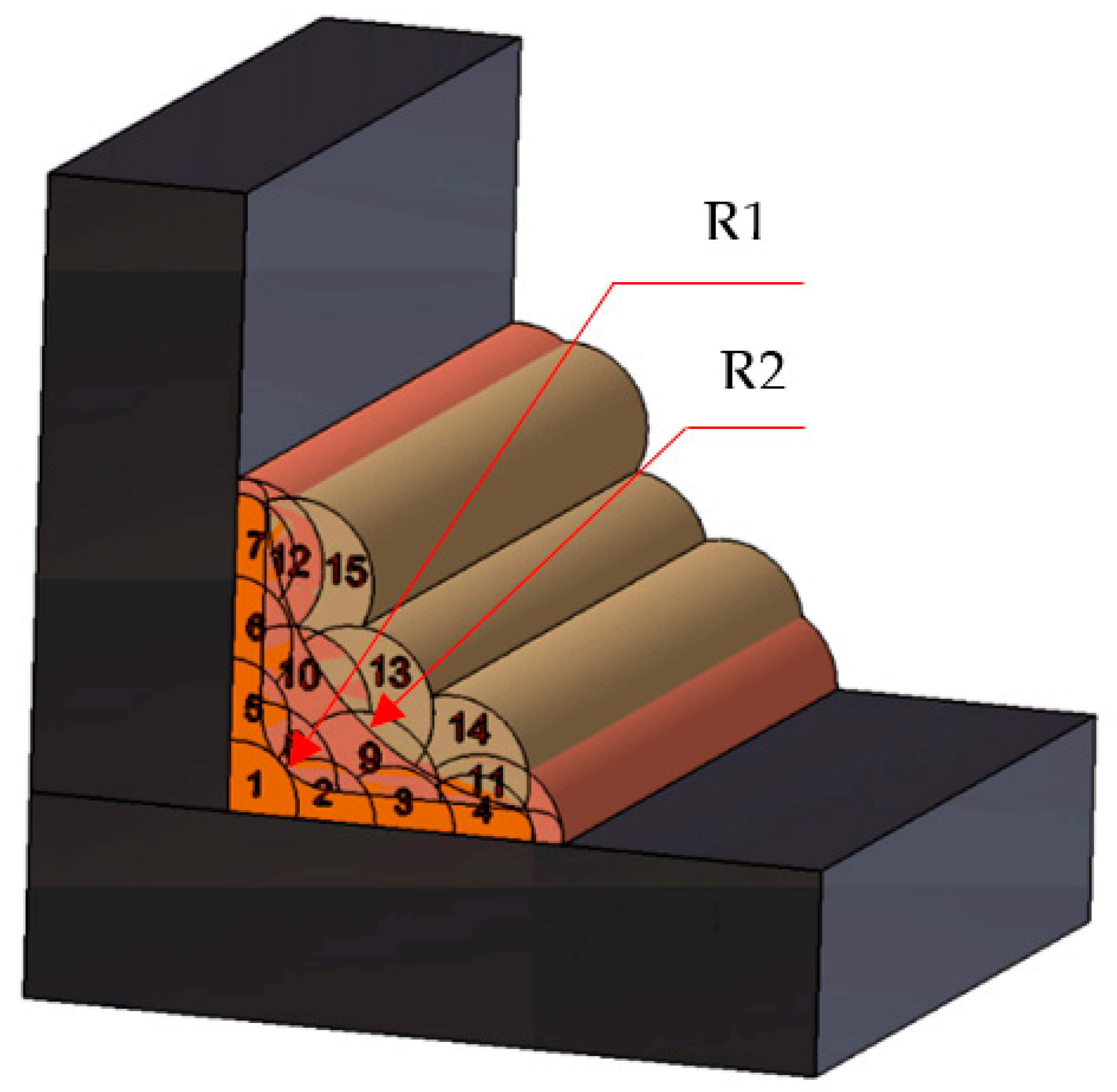
The order of deposition of the welding seams, through TBW, for the made samples, is presented in Figure 2.
After the deposition of the first welding layer formed by the welding seams 1, 2, 3, 4, 5, 6, 7 (Figure 2), the welding layer was polished after a geometry characterized by the connecting radius R1 (Figure 2), by this being aimed at increasing the heat absorption at the following layers compared to the previous ones, thus reducing the HAZ granulation adjacent to the previous layer. In fact, the aim is to overlap and position the successive welding seams, so as to produce a tempering of the previously deposited adjacent seam. The connection radius R1 can take different values in the range R1 = 0.5–3.5 mm. The size of the connecting radius R1 can substantially influence the tempering process of the weld bead and, at the same time, can have influences on the way in which the next welding layer will be deposited.
In the next stage of the welding process, the second welding layer formed by the welding seams 8, 9, 10, 11, 12 was deposited, Figure 2. These welding seams were subjected to a grinding process obtaining the connection radius R2, Figure 2, which can take values in the range R2 = 11–14 mm. Additionally, the realization of the connection radius R2 aims at an improvement of the tension process of the welding bead and, at the same time, of better conditions for the deposition of the next welding layer.
The last stage of obtaining the welded joint consisted in the deposition of a new welding layer formed by the welding seams 13, 14, 15, Figure 2. Given the fact that the welded joint is obtained by performing two-radius grinding, R1 and R2, respectively, there is the problem of optimizing the values of these radii so as to obtain the best performance in operation for the welded joint.
In order to be able to apply the TBW technique correctly, there must be a correlation between the welding speed and the amount of heat (linear energy) that is to be introduced into the part. To have a favorable effect following the application of the TBW technique, it is recommended to overlap the welding seams by at least 50% over those previously deposited. Taking into account the previous recommendations, several steps were taken to achieve the TBW welded joint, respecting certain parameters of the technological welding process. Thus, the first welding layer, consisting of welding seams 1–7, was made using a coated electrode with a diameter of Φ2.5 mm and small linear energy. The rows should overlap by about 50% over each other. The parameters of the welding regime when welding the first layer are presented in Table 5.This second welding layer, which includes the welding seams 8–12, was made using an electrode with a diameter of Φ3.2 mm, using a higher linear energy than the first layer, and the parameters of the welding regime used are presented in Table 5. For the realization of the last layer, which includes layers 13–15, electrodes with a diameter of Φ4 mm were used, and the parameters of the welding regimes are presented in Table 5. For the realization of this layer the welding speed was reduced compared to the case of layer deposition the second, obtaining the increase of the linear energy that will determine the finishing of the granulation in HAZ of the second deposited layer.
When welding specimens using the TBW technique, it is necessary to establish a correlation between welding speed and linear energy, dosed into the part. In fact, the aim is to reduce the granulation in HAZ. The change of granulation in HAZ depends on the following three factors: the chemical composition of the base material which can be assessed by the value of carbon equivalent (Ce), whose increase leads to increased hardness and reduced plasticity properties; cooling rate, which is desirable to be as low as possible, because at high cooling rates, hard out-of-balance compounds appear which increase the cracking tendency and the linear energy which represents the amount of heat introduced into the part during welding and it can be determine with Equation (1). At the first welding layer, it is recommended to limit the linear energy and the preheating temperature in order to avoid the increase of the grains in the area with coarse granulation of the thermomechanical area of influence.
E l = U I V s   ( J / mm )
where: U is the welding voltage, I—the intensity of the welding current; Vs—welding speed.

2.3. Programming of Experiments

Since the main objective of the paper is to analyze how the values of the radii R1 and R2 influence the operating performance of welded constructions, it was proposed to use the method of factorial experiments for programming experiments. Thus, for the two radii, four levels of values were proposed, namely for R1 = 0.5; 1.0; 2.5; 3.5 mm, and for radius R2 = 11; 12; 13; 14 mm. In these conditions, considering the fact that 2 variable parameters were established, each having 4 levels, 16 types of specimens were made, according to those presented in Table 6.
By using the method of factorial experiment, it was necessary to perform a minimum number of experiments 24 (16-experiments). This method was used to observe the fatigue behavior of different types of samples (16 types). Minimum, average and maximum values for the radii R1 and R2 were considered. The average values for R1 were 1.5 mm and 2.5 mm respectively, and for R2 they were 12 mm and 13 mm respectively. By applying this method and the statistical processing of the obtained results, mathematical models can be determined which can establish the dependence relation between the fatigue resistance of the welded constructions and the values of the radii R1 and R2 respectively. Additionally, 16 types of experiments were programmed for three types of variable loads F1 = ±8 kN: F2 = ±10 kN: F3 = ±12 kN. Three levels were chosen for the applied loads in order to be able to observe the fatigue behavior of the welded joints, at a 50% increase of loads.
All 16 types of realized samples were analyzed in terms of fatigue behavior, hardness of the material in the area of the welded joint, residual stresses measurement and the metallographic structure obtained.

2.4. Testing the Fatigue Behavior

Due to the fact that these types of welded constructions are subject to variable stresses, it was necessary to analyze their behavior in terms of their behavior at the fatigue stress. Thus, a compression traction cycle with a frequency of 10 Hz was applied. For the fatigue testing, a LVF 100 HM fatigue test machine (Saginomiya Seisakusho, Tokyo, Japan) was used. The fatigue test machine has the following characteristics: maximum static load of ±100 kN; maximum dynamic load of ±100 kN; maximum working frequency of 50 Hz; 100 mm piston stroke; a distance between the fastening devices of 1200 mm; overall dimensions: 900 mm × 600 mm × 2510 mm; weight of about 830 kg; working pressure from 44 to 200 bar; pump flow of 44 L/min at 200 bar. The values of the forces applied to the four types of samples are presented in Table 7.
The 16 samples were subjected to fatigue, under the conditions specified in Table 7, until they broke. To calculate the number of stress cycles to break (N), using Equation (2), the time after which each sample was broken was timed. Thus, knowing the stress time until the rupture of each sample, it is possible to calculate the number of cycles until rupture:
N = t·F
where: N represents number of cycles until breaking; t—time, in seconds; F—the applied frequency.
To determine the families of functions that should be as close as possible to the experimentally determined values, the mathematical program MathCad (Parametric Technology Corporation, Boston, MA, USA) was used. By plotting these functions, the fatigue durability curves of the samples (Wohler curves) were obtained. With the help of these curves it was possible to assess the time behavior of the samples in terms of fatigue stress. Wohler curves actually represent the relationship between the applied normal stress and the number of cycles to break. Given the fact that in the case of these categories of specimens there are two types of material in their structure, namely the base material and the material in the weld bead, it was approximated that the linear part of these curves can be expressed by a logarithmic function of the type shown in Equation (3): where lgA represents the intersection of the curve with the vertical axis, 1/p represents the slope of the line, σ represents the normal stress variation due to the variation of the force applied between a minimum and a maximum and n represents the number of cycles. Equation (3) represents the law of variation of the durability curve in linear coordinates. Equation (3) can also be written in the form of equation (4). Additionally, if IgA is considered to be equal to a certain value r, Equation (4) can also be written in the form (5), which in turn can be written in the form of the Equation (6):
lgN = lgA p lg σ
lg ( N σ p ) = lgA
10 r = N Δ σ p
σ = 10 r N p
where: lg A represents the intersection of Wohler curves with vertical axis; 1/p—is the slope of the line; σ—the normal stress that appeared as a result of the variation of the applied force between a maximum and a minimum; N—number of cycles.

2.5. Determination of the Hardness of the Material from the Welded Joint

In order to determine the hardening of certain areas of the welded joints, the microdurities HV0.2 were determined, and the distance between the impressions was at least 0.5 mm and the pressing time of 15 seconds, applying a load of 1000 g, taking into account the indications EN ISO 9015-1: 2011. Under these conditions, the hardnesses were measured in 8 points in the area of the deposited welding bead, 5 points in the HAZ and 5 points in the area of the base material. These points were established at a certain distance from the diffusion line, d, as follows: for the welding material −8–0 mm; for HAZ 0–4 mm; for the base material 4–8 mm. A Vickers ZHV30 hardness gauge (ZwickRoell Kennesaw, GA, USA) was used to measure hardness.

2.6. Analysis of the Metallographic Structure of the Material in the Welded Joint

In order to identify the correlation between the fatigue strength of the welded joints and the hardness of the materials in the welded joint, an analysis of the metallographic structure was performed. This analysis was performed for the specimens with the best and the weakest characteristics. The analysis of the metallographic structure from the area of the basic material, HAZ, the diffusion area and the material from the welding bead was taken into account. Microstructural research and chemical analysis of laser-coated samples were performed using an FEI Inspect-F scanning electron microscope (SEM) equipped with an energy dispersion spectroscopy detector (ThermoFisher, Tokyo, Japan).

3. Results and Discussion

3.1. The Results of the Analysis of the Fatigue Behavior

In order to carry out the research to highlight the fatigue behavior of the samples, a total of 80 samples were performed, i.e., five for each of the 16 types obtained under the conditions presented in Table 5 and Table 6. All these samples were tested under the loading conditions presented in Table 7. Each type of sample was subjected to tests with the help of fatigue testing machines. Each of the 16 types of samples were subjected to variable loads F1 = ±8 kN; F2 = ±10 kN; F3 = ±12 kN. Thus, after testing all the samples, a series of results were obtained in terms of fatigue behavior, and the results were processed using the STATISTICA 7.0 (Stafsoft, Inc., Tulsa, OK, USA) software. The purpose of this statistical processing of the experimental data was to establish the optimal values for the radii R1 and R2 for which the best fatigue behavior of the welded joints made by TBW is obtained. These experimental results were processed both graphically and analytically, identifying mathematical models that can determine the dependence of the number of stress cycles (N) that the samples withstood depending on the values of radii R1 and R2.
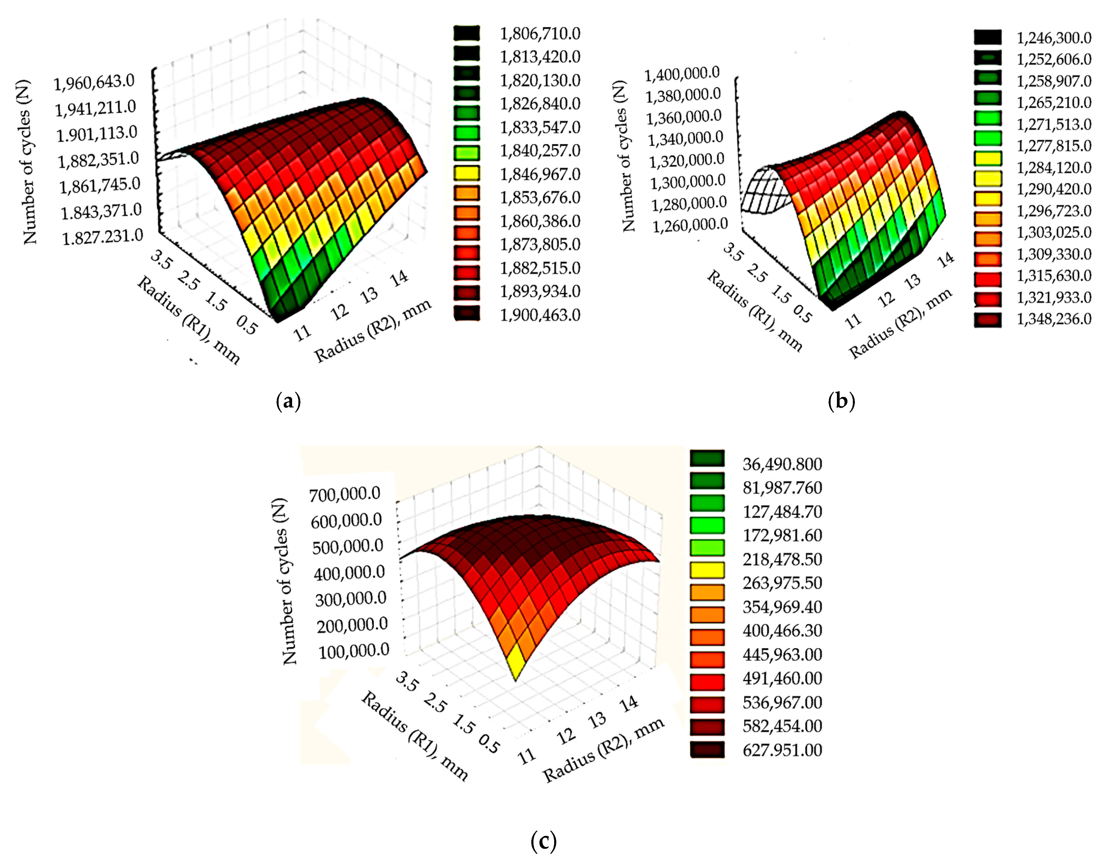
In the first stage, the samples were subjected to fatigue stress with a load F1 = ±8 kN. The best sample, in terms of fatigue stress, in the conditions mentioned, was the S7, which was made in the conditions of execution of radii R1 = 1.5 mm and R2 = 13 mm. The lowest behavior at the request of fatigue had the sample S1, which was made in the conditions of execution of some radii R1 = 0.5 mm respectively R2 = 11 mm. Additionally, from the analysis of the fatigue resistance values of the specimens, for this loading condition, it was observed that the difference between number of cycles which resisted the sample S7, respectively S1, was a small one, of approximately 8.96%. This demonstrates that, in the case of low loads, the influence of the welded construction design achieved by the TBW technique on fatigue strength is very low. However, it could be noticed that the best fatigue resistance, for, F1 = ±8 kN, had the samples with average values for the radii R1 and R2 respectively.
In the second stage, the samples were tested for fatigue under the conditions of applying a load F2 = ±10 kN. In this stage, the best results in terms of fatigue behavior were obtained in the case of the S10 sample, performed under the conditions of execution of some radii R1 = 2.5 mm and R2 = 12 mm. Additionally, the lowest behavior at the request of fatigue had the sample S1, which was made under the conditions of execution of radii R1 = 0.5 mm and R2 = 11 mm. The results obtained in this stage of the research showed that, even for the case where the loads F2 = ±10 kN are applied, a small difference of 8.47% is obtained, between the largest and the smallest number of cycles at which resisted the samples. This demonstrated once again that, for the fatigue load of low-load test specimens, no substantial increases in fatigue strength are obtained at the same time with with the optimization of welded construction design achieved by the TBW technique.
In a last stage of the research in terms of fatigue behavior, the samples were subjected to variable load with F3 = ±12 kN, and the best fatigue behavior was the S11 sample, which was made in the conditions of execution of some radii R1 = 2.5 mm, respectively R2 = 13 mm. Additionally, the lowest fatigue resistance had the S16 sample, which was made in the conditions of execution of some radii R1 = 3.5 mm and R2 = 14 mm. From the analysis of these results it was observed that the optimization of the welded construction design achieved by the TBW technique greatly influences the fatigue behavior of the highly demanded welded constructions. Thus, for these loading conditions, the difference between the minimum and maximum number of cycles at which the samples were broken was 63.25%. This demonstrates that the improved design of welded constructions made by the TBW technique greatly influences the fatigue strength of welded constructions which are strongly demanded in operation.
Also, all these results demonstrate that the best fatigue behavior is the samples that are made with average values of the two radii, namely R1 = 1.5–2.5 mm and R2 = 12–13 mm. This is justified by the fact that, if processing with very low values for R1 and R2 is adopted, a large amount of the layer of material deposited by welding is removed, which results in a substantial decrease in its total thickness. Thus, this justifies the results obtained, namely that for small values of radii R1 and R2 respectively the lowest fatigue strength of welded constructions is obtained. Additionally, if too high values are adopted for the radii R1 and R2, the tempering conditions of the weld seams worsen, and thus, the effects produced by the realization of welded joints by TBW technique, are substantially reduced resulting in a decrease in fatigue resistance of the samples.
By graphically processing the experimental results, the evolutions of the fatigue behavior of the samples were obtained. Thus, in Figure 3a is presented the dependence of the number of stress cycles in the conditions of applying a load F1 = ±8 kN, in Figure 3b in the conditions of applying the load F2 = ±10 kN, and in Figure 3c under the conditions of applying a load F1 = ±12 kN.
Thus, from the graphic analysis it was observed that the mode of variation of the number of cycles of radii R1, respectively R2, differs in the case of solicitation with the load F3 compared to the other types of loads. In the case of the load with load F3, the lowest resistance to fatigue had S16, which is achieved in the conditions in which the two rays have the highest values. At the same time, in the case of requesting samples with loads F1, F2 had the lowest fatigue resistance with the sample with S1, which is made with the lowest values for the radii R1 and R2 respectively.
All this demonstrates that there is an optimal value of the life of welded constructions made by TBW technique, depending on the thickness of the layer of material deposited by welding. Additionally, at high loads, the fatigue strength of the S1 sample decreases compared to the other samples because the processing with small R1 and R2 radii prevents achievement of the welded joint by the TBW technique in good condition, greatly reducing the thickness of the deposited material. All this demonstrated that welded structures made by the TBW technique should not be made with low values for radii R1 and R2 because they must withstand very high loads. Thus, it can be concluded that, with the increase of the loads of the welded constructions, it is indicated that the values of the radii R1 and R2 respectively not to be very high, in order to obtain the best possible resistance to fatigue. This can be explained by the fact that the realization of some processing with very large radii does not allow to obtain the desired effects when applying the TBW technique.
Through the statistical processing of the obtained experimental data, the influence of the values of the two rays on the fatigue resistance was established. Thus, the following values were obtained for the parameters that give us the way in which the two rays influence the resistance to fatigue:
for F1 = ±8 kN—R1beta = 0.031; R2beta = 0.969;
for F2 = ±10 kN—R1beta = 0.029; R2beta = 0.971;
for F3 = ±12 kN—R1beta = 0.028; R2beta = 0.961.
From the analysis of these values of the parameters (Rbeta) it is observed that the radius R1 has a reduced influence on the fatigue strength of the welded constructions, while the radius R2 has a very large influence. Additionally, the influence of the R1 radius grows with the increase of the stress conditions, due to the fact that an R2 radius, with a value as high as possible, can positively influence the fatigue resistance of the specimens.
At the same time, by processing the experimental data, the mathematical models were established, with the help of which the number of cycles that the samples can withstand can be determined according to the values of radii R1 and R2, respectively, and these mathematical models are presented in Table 8.
The model summary shows strong correlation, expressed by the value of R-Squared, over 98% for all three load forces. The mathematical models presented in Table 8 are adequate obtaining values close to R1 for R2. Thus, these models can be used to establish the number of stress cycles that a welded construction withstands depending on the values of the radii R1 and R2, respectively.
Also, in order to verify the adequacy of the mathematical models presented in Table 8, an analysis was performed using ANOVA, the results obtained being presented in Table 9. It was verified if the difference between observed value and predicted value is acceptable, the standard residual being also determined.
From the results presented in Table 9 it was observed that there are small differences between observed value and predicted value. Thus, the standard residual had a maximum value of 4.03493 which demonstrates that the predicted values using mathematical models can be used in practical applications without major errors. Additionally, the predicted values generally have lower values than the observed ones, which represents a reason to use in practice the obtained mathematical models.
From this analysis it results that the dependence between the number of cycles resisted by the welded joints required for fatigue and the values of the radii R1 and R2 respectively can be expressed by a mathematical model of polynomial type of degree 2:
N = i = 1 2 C i · R i + i , j = 1 2 C i j · R i · R j +   ε
where: Ri, Rj are welding polishing radii, Ci, Cij—numerical coefficients, ɛ—statistical random error term.
The graphical processing of the obtained results as well as the mathematical models can offer the optimal levels for the rays R1 and R2 respectively, but it does not indicate which of the rays has the most significant impact on the fatigue resistance of the samples. To determine the impact of radii values on fatigue strength, the ANOVA method was used, which is a robust method to determine the contribution of each factor and the significance of the optimization model. Thus, the Fischer test value (F value) and the sum of squares were determined. The p values below 0.05 or 5% were considered statistically significant. Thus, the values determined for p, respectively F are presented in Table 10.
From the analysis of the data presented in Table 10 it is observed that the radius R2 has a significant influence on the number of cycles in all 3 loading cases. An important aspect is that the radius R2 has a greater influence for the load with F3 = ±12 kN because in this case F = 55.40679 compared to the cases F1 = ±8 kN (F = 48.09998) and F2 = ±8 kN (F = 52.80922). Additionally, the radius R1 is significant for fatigue resistance, but has a smaller influence than R2 being obtained values for p < 0.05%, but different from zero. At the same time it was observed that the radius R1 has a greater influence in the case of F3 = ±12 kN when the lowest value for p of 0.000002 was observed, respectively the highest value for F of 55.40679.
The processing of experimental data using ANOVA highlights more clearly the results obtained in the case of fatigue tests. Thus, it is explained that in case of fatigue stress the samples had different behaviors in the sense that for the load F1 = ±8 kN the best behavior was the S7 sample, for the load F2 = ±8 kN the S10 sample respectively for the load F3 = ±12 kN, S11 sample.
Also, it was found that the realization of some processing with different radii of the deposited welding layers determines a substantial change of the fatigue behavior of the samples. The biggest difference was found when the samples were required to load F3 = ±12 kN. Thus, in this situation, the resistance to fatigue stress increased greatly, from Nmin =213,979 if R1 and R2 respectively do not have optimal values at Nmax = 582,454, if optimal values for R1 and R2 respectively have been used.
The results obtained in the experimental research allowed the selection of 5 types of specimens (S1, S7, S10, S11, S16) for which the durability curves (Wohler curves) were drawn. This selection was made considering the following: the S1 sample had the lowest resistance to fatigue in case of applying the load F1 = ±8 kN respectively F2 = ±10 kN; the S16 sample had the lowest fatigue resistance when applying the load F3 = ±12 kN; S11, S10, S7 had the best fatigue behavior in case of applying loads F1 = ±8 kN; F2 = ±10 kN respectively F3 = ±12 kN.
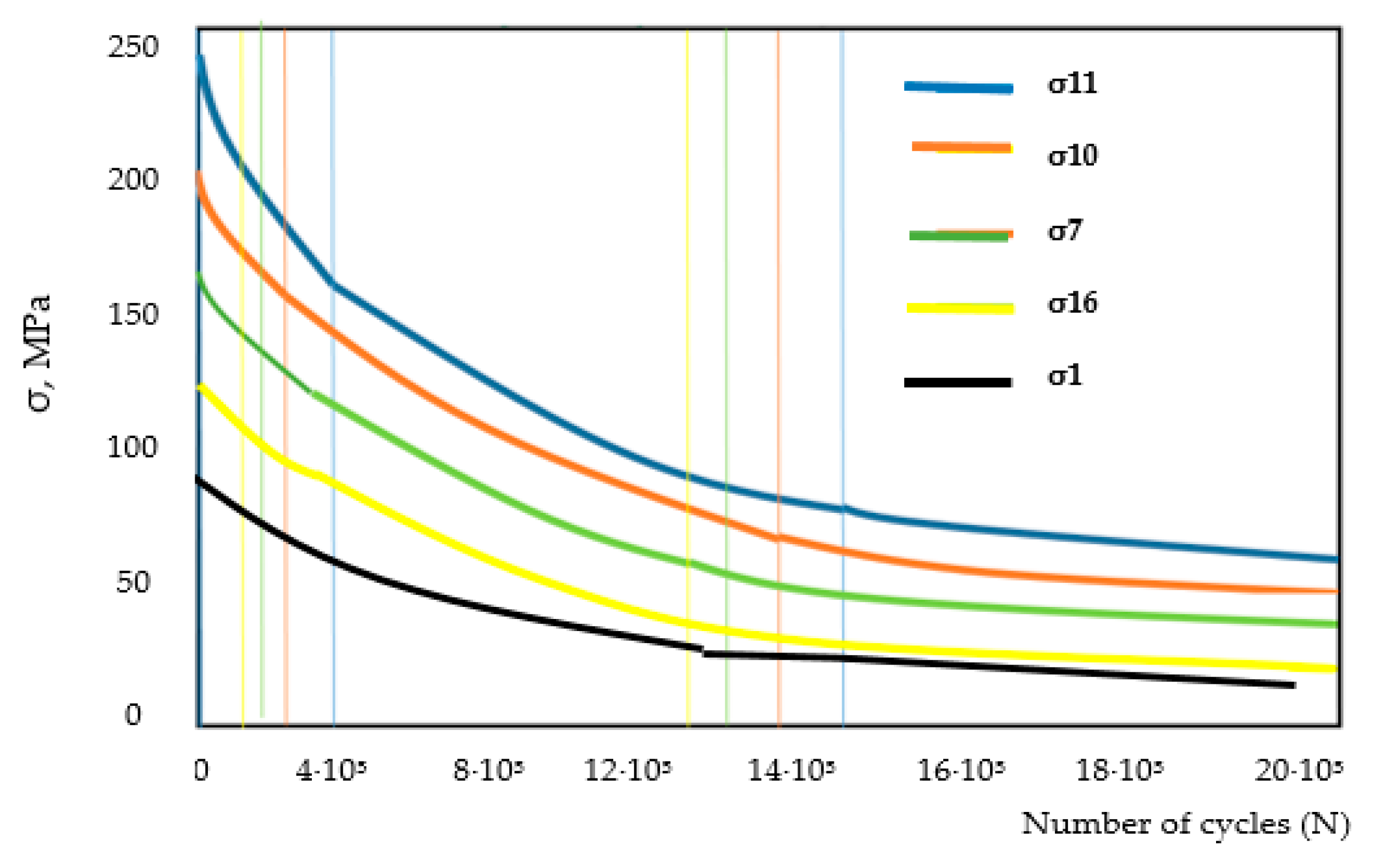
In conditions that on a graph on the ordinate (vertical axis) we have the stresses and on the horizontal we have the number of cycles until breaking, the durability curves are obtained. By mathematical processing of the results obtained from the fatigue tests, the values p1 = 2.2 and r1 = 4.8 were determined for the S1 sample, for which the graph of the function Δσ1 is closest to our points represented by the vector number of cycles denoted by N1 = (1,821,673; 1,267,311; 213,979) and the force vector denoted F = (12; 10; 8). In the same conditions were processed the data obtained for the S7, S10, S11 and S16 samples and were obtained for the S7 sample values p7 = 2.2 and r7 = 5.2, for the S10 sample the values p10 = 2.2 and r10 = 5.5, for the S11 sample the values p11 = 2.2 and r11 = 6.1 respectively for the S16 sample the values p16 = 2.2 and r16 = 5.0. Additionally, by processing these experimental data, the durability curves were drawn in linear coordinates, Figure 4, as follows: the S1 sample—curve σ1, the S7 sample—curve σ7, the S10 sample—curve σ10: the S11 sample—curve σ11, the S16 sample—curve σ16.
Also, using Equations (3)–(6) σ was calculated, the normal stress that appeared as a result of the variation of the force applied between a maximum and a minimum for the samples S1, S7, S10, S11, S16 under the mentioned stress conditions. The results for fatigue tests are presented in Table 11.
From the analysis of the durability curves presented in Figure 4 it was observed that none is asymptotic with respect to the horizontal axis, and the lowest value for σ was obtained in the case of the S10 sample, which shows that it has the best behavior at the request of fatigue. Therefore, these curves will intersect at some point with the horizontal axis, i.e., there is no value for an in load F for which there is an infinite lifetime for the analyzed specimens. Additionally, the closest values observed in the case of durability curves compared to the real values are obtained in the case of the S11 sample, but also in the case of other types of samples, the difference is very small, being in the range of 5–12%.
From Figure 4 it is observed that the best behavior at the fatigue request had the S11 sample, and the lowest resistance had the S1 sample. The explanation may be that, in the case of the S11 sample, a very good finishing of the structure occurs, resulting in much finer grains both in the area of additive material deposited by welding (WM) and in HAZ. Additionally, by achieving a better overlap of the welding seams, an appropriate heat treatment is applied to the layers of material previously deposited through a better distribution in the material of the heat resulting from the welding process. By reducing the granulation, there is a decrease in the stress concentration and, at the same time as a reduction in the micro-hardness, a significant increase in the fatigue life is determined. Under these conditions, it can be concluded that, by making the welded joint by TBW technique with optimal radii R1 = 2.5 mm, respectively R2 = 13 mm, a substantial increase of resistance to fatigue stress can be obtained.

3.2. Results Obtained after Measuring the Hardness of the Material in the Samples

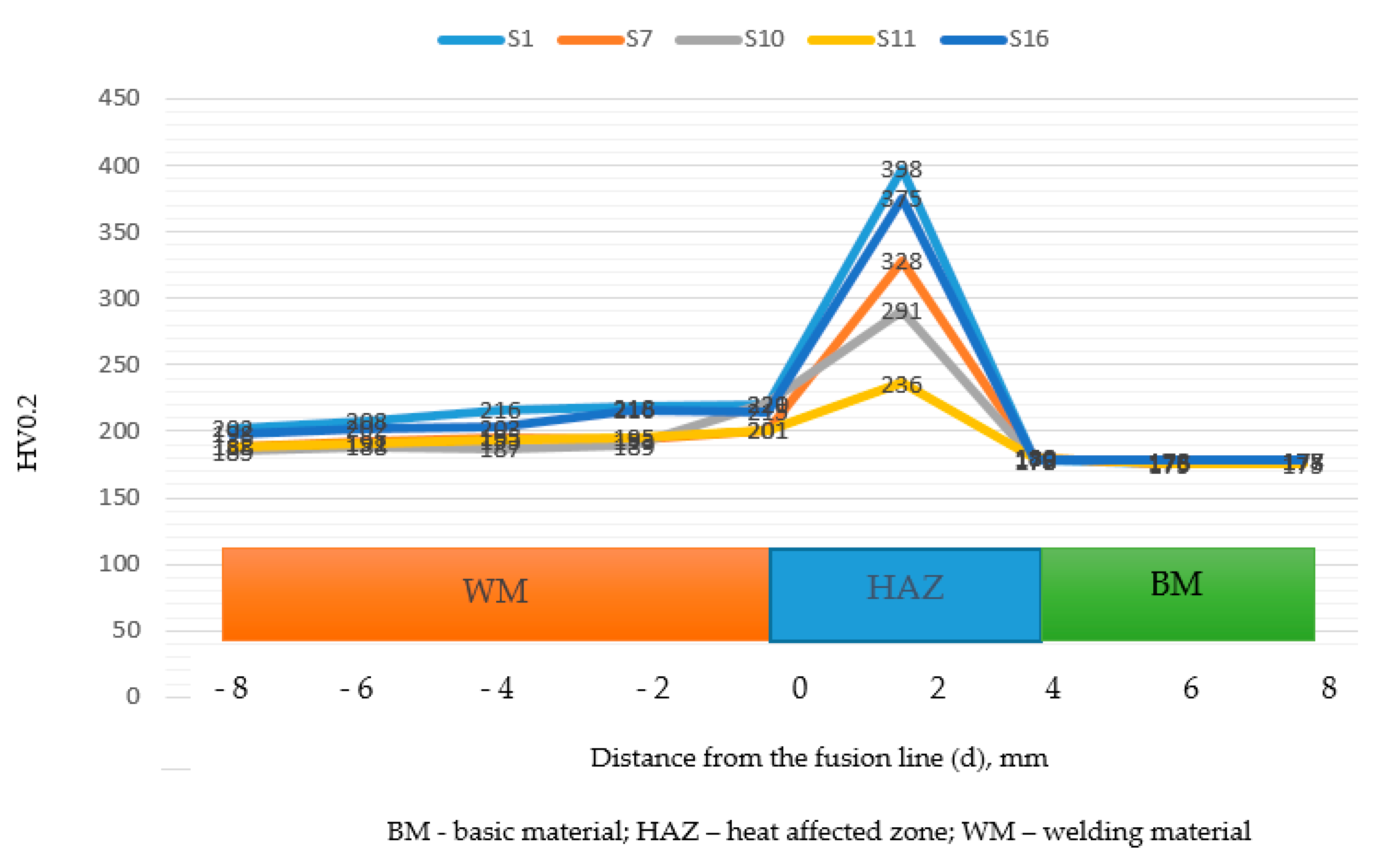
In order to measure the hardness of the material in the samples, three zones were taken into account, namely: the zone of the basic material (BM), the zone thermally influenced (HAZ), respectively the zone of additive material deposited by welding. The microhardness measurement points in the three zones were positioned in relation to the diffusion line, and this was considered as point 0, from which the distance of the other points is measured. Additionally, based on the results obtained in the process of testing the samples at the fatigue request, it was decided that the hardness tests be performed based on the samples selected in this stage, namely S1, S7, S10, S11 and S17 respectively. The measurement of the hardness of the material was imposed due to the fact that too high values of hardness in the HAZ can determine a reduced of the resistance of the samples to the fatigue stress. The results obtained from the hardness measurements of the material in the samples were processed graphically and are presented in Figure 5.
After the graphical processing of the experimental results obtained, Figure 5, it was found that the highest hardness values are found in HAZ near the melting line zone, where the highest amounts of martensite are found. The heat input during the welding process contributes to the transformation of soft microstructures into a hard structure such as martensite. The highest hardness value was 388HV0.2 which is approximately at the limit imposed by the AWS standard (AWS D3.6M: 2010). However, S7 and S16 specimens have very high values of material hardness in HAZ, which demonstrates that the realization of a welded structure in the technological conditions specified for S7, S16 specimens, can create problems in operation. Additionally, the S11 specimen has the lowest hardness value of the HAZ material, which demonstrates that the adoption of optimal values for R1 and R2 has a positive influence, in the sense that, thus, the rapid cooling of the material is prevented but also the increase of heat during the welding process.
At the same time, obtaining the lowest hardness in HAZ is justified by the fact that in this zone it is avoided to obtain hard structures formed of martensite and a series of specific structures corresponding to normalization annealing are obtained, namely ferrite and fine pearlite. Thus, and by the hardness analysis performed, the good behavior of the S11 sample at the fatigue solicitation is justified.
The results obtained in the case of the S11 sample demonstrate that the adoption of optimal values for the radii R1 and R2 respectively can create conditions for an increase in the overlap of the weld seams. By increasing the overlap of the welding seams, the tempering effect also increases and the size of the grains in the HAZ decreases, further justifying the effects obtained in the fatigue resistance and hardness tests, respectively. Thus, by applying the welding technique (TBW), the weldability of the materials can be improved, obtaining a decrease of the maximum hardness in HAZ.
Thus, it was observed that by changing the values of the two rays R1 and R2, respectively, the degree of overlap of the deposited materials also changes. Thus, the higher the degree of overlap, the lower the hardness in the HAZ and the welding material. It was also observed that the change in the degree of overlap does not cause a high variation in hardness in the base material. By reducing the hardness of the material in HAZ, a limitation of one of the factors is obtained that is added to the initiation of the cold cracks, and all these contribute to the reduction of crack sensitivity, a fact confirmed by other research [1].

3.3. Residual Stresses Measurement

The residual stresses analysis from the welded joints made by the TBW technique gives us an image of how the tempering process was performed. In this sense, residual stresses were measured for the five previously analyzed samples (S1, S7, S10, S11, S16). Thus, the hole-drilling method was used to determine residual stresses. For the 5 analyzed samples the 8 mm × 8 mm strain gauge rosettes were bonded on each sample at two locations “A” and “B” as shown in Figure 6. The strain rosettes were placed exactly at the edge of the weld toe, i.e., the distance between the center of the strain rosettes to the edge of the weld toe was 4 mm. This decision was made given that the dimensions of the strain rosettes were 8 mm × 8 mm. Regarding the value of the angle β it was measured clockwise from the location of the reference gauge to the direction of σmax. The values of the maximum and the minimum residual stresses and the angle β are shown in Table 12.
From the data presented in Table 12 it is observed that the realization of welded joints by TBW technique with different values for the radii R1 and R2 respectively influences the residual stresses values. It is also observed that the minimum values for residual stresses were obtained in the case of the S1 sample. This demonstrates that the degree of coverage obtained during welding, but also the thickness remaining after polishing the layers of deposited material influences residual stresses. Thus, in the case of a larger polishing radius, a high degree of overlap of the deposited material layers can be obtained, but the thickness of the processed layer can influence the tempering process and implicitly the properties of the welded joint.

3.4. Analysis of the Microstructure of Materials from HAZ

The analysis of the microstructure of the materials from the welded joint was necessary in order to be able to observe the way in which it influences the resistance to the fatigue stress of samples, respectively hardness of the material. Considering the fact that for the other research the S1, S7, S10, S11, S16 samples were chosen, the decision to analyze the microstructure of these samples was further maintained. Additionally, knowing that by applying the TBW technique a substantial change in the structure of materials can be obtained, especially in HAZ [4], the research analyzed the microstructure of the material in this area for the 5 samples. The microstructure in the HAZ area for the 5 analyzed samples is presented in Figure 7.
Following the analysis of the microstructures presented in Figure 7, it was observed that the adoption of different values for the radii R1 and R2 determines a substantial change in the metallographic structure of the material in HAZ. From the analysis of the microstructures it was found that the most advantageous situation from the point of view of the metallographic structure was registered in the case of the S11 sample, Figure 7d, when, due to the fact that the “tempering” effect was achieved in the best conditions, normalized structures formed of ferrite and fine perlite were obtained.
This is due to the “tempering” effect of the additional weld seams on the previous ones. The processing performed with different values of the radii R1 and R2 respectively influences the overlapping mode of the welding seams, and a better overlap increases the tempering effect and decreases the grain size in HAZ. Thus, it was observed that the realization of some processing of the welding seams with radius R1 = 2.5 mm respectively R2 = 13 mm determines the best tempering effect and the best metallographic structure in HAZ.
Regarding the microstructure of the S16 sample, Figure 7e, made with the highest values for the connection radii R1 and R2, this is an inadequate one and consists of large, acicular grains, being present mostly a martensitic type structure. A structure similar to that of the S16 specimen was also observed in the case of the S1 sample, Figure 7a, but in this case a bainitic type is also present in the structure. Thus, it can be concluded that the realization of some processing of the welding layers with too big or too small connection radii prevents the achievement of the “tempering” effect. Thus, in case of processing with very small values for radii R1 and R2, a large amount of material deposited by welding is removed, and for very high values for radii R1 and R2 a very small amount is removed from the amount of material deposited, which causes a sharp decrease in the “tempering” effect.
The presence of the martensitic structure in the case of the S16 sample also explains its inappropriate behavior when tired. Additionally, the presence in HAZ of a metallographic structure formed by ferrite and fine perlite determines a considerable increase of the fatigue resistance, which is observed in the case of the S11 sample. Thus, it was found that when an area of a previous weld is properly reheated by the subsequent weld, it will form a structure composed of finer ferrite and perlite.
In the case of the S11 sample, by performing some processing with the value R1 = 2.5 mm and R2 = 13 mm a degree of bead overlap of approximately 85% was obtained, and, thus, the best tempering effect was obtained for the investigated samples. With the increase of the degree of overlap, there was a decrease in the size of the grains, which was to be expected in accordance with previous works [1,28]. Additionally, the HAZ microstructure has been considerably improved by the appearance of areas with finer perlite (average size 8.2 μm). Thus, by applying the TBW technique with optimal values for radii R1 and R2, a decrease in the hardness of the HAZ material is obtained. As a result, these types of welded joints can be used especially for equipment working at low temperatures.
In the case of the S11 specimen, a corresponding overlap of the weld seams was obtained, which determined the appearance in HAZ of a metallographic structure that also contains fine perlite. Its presence explains the lower hardness of the HAZ material for the S11 sample.
Also, from the microscopic analyzes performed, no cracks were observed in the weld seams, which proves that no cracks appeared after the first bead deposition because in previous investigations [29], it was found that TBW could not repair the micro-cracks that formed during first bead welding. However, TBW could help avoid cold cracks that could occur after welding [30].
From the allure of the durability curves, determined with the help of experimental data and with the help of a mathematical software, it was observed that they are not asymptotic to the horizontal axis, at a given moment they can intersect with this axis. This means that a “fatigue resistance”, that represents the force or tension of stress, for which the test piece(s) withstand an infinite number of stress cycles, could not be detected for any set of specimens. So, even for welding with the TBW technique, a stress or tension force cannot be found, for which we have an infinite fatigue life. We can only say that in the case of welding with TBW technique we have a much longer fatigue life than in the case of welding without TBW technique, and this duration can be considerably increased if optimal values are chosen for the R1 and R2 radii respectively.
The optimization of the values for R1 and R2 respectively determines a decrease of the hardness of the HAZ material, and all these are explained by the fact that the use of the TBW technique in optimal conditions requires the application of a thermal treatment for the normalization of the HAZ material.
It has also been confirmed that the mechanical properties of a welded joint as well as the microstructure depend primarily on the heat input and the cooling rate [31,32]. An improvement of the results obtained in the application of the TBW technique would be the application of ultrasonic vibrations due to the fact that a high frequency mechanical wave can improve the welding process [33,34]. Thus, further research is needed to improve the welding technique with the application of ultrasonic vibration, especially as [35,36,37] points out that there are few reports that focus on the correlation between ultrasonic vibration and TBW welding, which allows an improvement of the mechanical properties of the metal in the welded joint.
The research presented in this paper confirms that the application of the TBW technique is indicated if it is necessary to make welded metal constructions of large size, from materials susceptible to cold cracking. Additionally, this method of making corner welded joints can be applied to metal constructions that would require post-weld heat-treatment (PWHT). Thus, by applying the TBW technique, post-weld heat-treatment (PWHT) can be eliminated, thus ensuring a reduction of costs but also very good use properties.

4. Conclusions

The experimental results obtained in the research showed that the processing of welding seams with different radii, in the case of applying the TBW technique, determines an improvement in the operating performance of welded constructions. This can be explained by the fact that the adoption of optimal values for radii determines a better distribution of heat in the welding process, but also an appropriate overlap of the welding seams.
The conclusions that can be systematized, based on discussions and experimental results, are the following:
  • Fatigue resistance of the samples differed greatly depending on the values of the rays. Thus, the resistance to fatigue stress increased greatly from Nmin = 213,979 if R1 and R2 respectively do not have optimal values (R1 = 0.5 mm, R2 = 11 mm) at Nmax=582,454 if optimal values were used for R1 and R2 respectively (R1 = 2.5 mm, R2 = 13 mm ) for the situation in which the highest value of the load F3 = ±12 kN is applied;
  • The highest value of material hardness in HAZ was 388HV0.2, approximately at the limit imposed by the AWS standard (AWS D3.6M: 2010), but the lowest value was 236HV0.2 obtained if R1 = 2.5 mm respectively R2 = 13 mm;
  • Research has shown that choosing optimal values for R1, R2 causes reduced residual stresses in the welded joint;
  • From the analysis of the microstructures in HAZ, it was observed that in the case of welding with TBW technique with values R1 = 2.5 mm respectively R2 = 13 mm, fine-grained perlite and ferrite microstructures appear, as a result of the heat treatment effect exerted by the additional welding seams on the previous ones, in the context of the overlapping of the welding seams. At the opposite pole, in the case of welding by TBW technique with the use, with the use of values of radii R1 = 0.5 mm, R2 = 11 mm, as a result of the introduction of a large amount of heat in the welded joint, hard microstructures appeared, with constituents of acicular martensite.
Following the research and conclusions it can be said that the realization in optimal conditions by TBW technique of welded joints determines an improvement of the performance of welded constructions, and in future research will follow the way in which the roughness obtained by cutting welding seams influences their lifespan.

Author Contributions

The author contributed to the research presented in this paper and to the preparation of the final manuscript.

Funding

This research was funded by “Lucian Blaga” University of Sibiu and Hasso Plattner Foundation, research grant LBUS-RRC-2020-01.

Acknowledgments

Project financed from Lucian Blaga University of Sibiu, The Research centre for sustainable products and processes & Hasso Plattner Foundation research action LBUS-RRC-2020-01.

Conflicts of Interest

The author declare no conflict of interest.

References

  1. Tomków, J.; Fydrych, D.; Rogalski, G. Dissimilar underwater wet welding of HSLA steels. Int. J. Adv. Manuf. Technol. 2020, 109, 717–725. [Google Scholar] [CrossRef]
  2. Li, H.; Liu, D.; Ma, Q.; Guo, N.; Song, X.; Feng, J. Microstructure and mechanical properties of dissimilar welds between 16 Mn and 304 L in underwater wet welding. Sci. Technol. Weld. Join. 2018, 24, 1–7. [Google Scholar] [CrossRef]
  3. Rogalski, G.; Świerczyńska, A.; Landowski, M.; Fydrych, D. Mechanical and microstructural characterization of TIG welded dissimilar joints between 304L austenitic stainless steel and incoloy 800HT nickel alloy. Metals 2020, 10, 559. [Google Scholar] [CrossRef]
  4. Tomków, J.; Rogalski, G.; Fydrych, D.; Łabanowski, J. Advantages of the application of temper bead welding technique during wet welding. Materials 2018, 12, 915. [Google Scholar] [CrossRef] [Green Version]
  5. Benedetti, M.; Torresani, E.; Fontanari, V.; Lusuardi, D. Fatigue and fracture resistance of heavy-section ferritic ductile cast iron. Metals 2017, 7, 88. [Google Scholar] [CrossRef] [Green Version]
  6. Yuan, H.; Zhang, W.; Castelluccio, G.M.; Kim, J.; Liu, Y. Microstructure-sensitive estimation of small fatigue crack growth in bridge steel welds. Int. J. Fatigue 2018, 112, 183–197. [Google Scholar] [CrossRef] [Green Version]
  7. Dimitrescu, A.; Nitoi, D.F.; Dobrota, D.; Apostolescu, Z.; Apostolescu, Z. Researches and studies regarding brazed aluminium alloys microstructure used in aeronautic industry. Metalurgija 2015, 54, 583–586. [Google Scholar]
  8. Truong, T.-T.; Hsu, Q.-C.; Tong, V.-C. Effects of solid die types in complex and Large-scale aluminum profile extrusion. Appl. Sci. 2020, 10, 263. [Google Scholar] [CrossRef] [Green Version]
  9. Wang, F.; Yang, X.; Cui, L.; Yin, Y. Fabricating defect-free API X65 steel welds under underwater wet conditions using Friction Taper Plug welding. Mater. Manuf. Process. 2016, 31, 2123–2129. [Google Scholar] [CrossRef]
  10. Rogalski, G.; Łabanowski, J.; Fydrych, D.; Tomków, J. Bead-on-plate welding on S235JR steel by underwater local dry chamber process. Pol. Marit. Res. 2014, 21, 58–64. [Google Scholar] [CrossRef] [Green Version]
  11. Abe, F. Coarsening behavior of lath and its effect on creep rates in tempered martensitic 9Cr-W steels. Mater. Sci. Eng. A 2004, 387–389, 565–569. [Google Scholar] [CrossRef]
  12. Sun, Y.L.; Obasi, G.; Hamelin, C.J.; Vasileiou, A.N.; Flint, T.F.; Francis, J.A.; Smith, M.C. Characterisation and modelling of tempering during multi-pass welding. J. Mater. Process. Technol. 2019, 270, 118–131. [Google Scholar] [CrossRef]
  13. Ren, S.; Li, S.; Wang, Y.; Deng, D.; Ma, N. Predicting welding residual stress of a multi-pass P92 steel butt-welded joint with consideration of phase transformation and tempering effect. J. Mater. Eng. Perform. 2019, 28, 7452–7463. [Google Scholar] [CrossRef]
  14. Ghojel, J.I.; Ibrahim, R.N. Computer simulation of the thermal regime of double-loop channel induction furnaces. J. Mater. Process. Technol. 2004, 153–154, 386–391. [Google Scholar] [CrossRef]
  15. Yu, L.; SaSa, M.; Ohnishi, K.; Kameyama, M.; Hirano, S.; Chigusa, N.; Sera, T.; Saida, K.; Mochizuki, M.; Nishimoto, K. Neural network based toughness prediction in HAZ of low alloy steel produced by temper bead welding repair technology. Sci. Technol. Weld. Join. 2013, 18, 120–130. [Google Scholar] [CrossRef]
  16. Albuquerque, V.; Silva, C.; Moura, C.; Aguiar, M.; Farias, J. Effect of nonmetallic inclusion and banding on the success of the two-layer temper bead welding technique. Mater. Des. 2009, 30, 1068–1074. [Google Scholar] [CrossRef]
  17. Wang, Y.; Kannan, R.; Li, L. Identification and characterization of intercritical heat-affected zone in As-welded grade 91 weldment. Metall. Mater. Trans. A 2016, 47, 5680–5684. [Google Scholar] [CrossRef]
  18. Zondi, M.C. Factors that affect welding-induced residual stress and distortions in pressure vessel steels and their mitigation techniques: A review. J. Press. Vessel Technol. 2014, 136, 040801. [Google Scholar] [CrossRef]
  19. Ebrahimi, S.M.; Farahani, M.; Akbari, D. The influences of the cyclic force magnitude and frequency on the effectiveness of the vibratory stress relief process on a butt welded connection. Int. J. Adv. Manuf. Technol. 2019, 102, 2147–2158. [Google Scholar] [CrossRef]
  20. Hu, Y.; Shi, Y.; Sun, K.; Shen, X.; Wang, Z. Microstructure and mechanical properties of underwater hyperbaric FCA-welded du-plex stainless steel joints. J. Mater. Process. Technol. 2018, 261, 31–38. [Google Scholar] [CrossRef]
  21. Wei, P.; Li, H.; Liu, J.; Li, S.; Zhang, Y.; Zhu, Y.; Lei, Y. The effect of water environment on microstructural characteristics, composi-tional heterogeneity and microhardness distribution of 16Mn/304Ldissimilar welded joints. J. Manuf. Process. 2020, 56, 417–427. [Google Scholar] [CrossRef]
  22. den Besten, H. Fatigue criteria classification, modeling developments and trends for welded joints in marine structures. Ships Offshore Struct. 2018, 13, 787–808. [Google Scholar] [CrossRef]
  23. Dehghani, A.; Aslani, F. A review on defects in steel off shore structures and developed strengthening techniques. Structures 2019, 20, 635–657. [Google Scholar] [CrossRef]
  24. Tomków, J.; Janeczek, A. Underwater in situ local heat treatment by additional stitches for improving the weldability of steel. Appl. Sci. 2020, 10, 1823. [Google Scholar] [CrossRef] [Green Version]
  25. Tomków, J.; Fydrych, D.; Rogalski, G.; Łabanowski, J. Temper bead welding of S460N steel in wet welding conditions. Adv. Mater. Sci. 2018, 18, 5–14. [Google Scholar] [CrossRef] [Green Version]
  26. Wenbin, G.; Dongpo, W.; Fangjie, C.; Xinjie, D.; Caiyan, D.; Wei, X. Microstructural and mechanical performance of underwater wet welded S355 steel. J. Mater. Process. Technol. 2016, 238, 333–340. [Google Scholar]
  27. Lant, T.; Robinson, D.L.; Spafford, B.; Storesun, J. Review of weld repair procedures for low alloy steels designed to minimise the risk of future cracking. Int. J. Press. Vessels Pip. 2001, 78, 813–818. [Google Scholar] [CrossRef]
  28. Hanzaei, A.T.; Marashi, S.; Ranjabarnodeh, E. The effect of hydrogen content and welding conditions on the hydrogen induced cracking of the API X70 steel weld. Int. J. Hydrogen Energy 2018, 43, 9399–9407. [Google Scholar] [CrossRef]
  29. Tomków, J.; Łabanowski, J.; Fydrych, D.; Rogalski, G. Cold cracking of S460N steel in water environment. Pol. Marit. Res. 2018, 25, 131–136. [Google Scholar] [CrossRef] [Green Version]
  30. Chen, H.; Guo, N.; Zhang, X.; Cheng, Q.; Zhou, L.; Wang, G. Effect of water flow on the microstructure, mechanical performance, and cracking susceptibility of underwater Q235 and E40 steel. J. Mater. Process. Technol. 2020, 277, 116435. [Google Scholar] [CrossRef]
  31. Prajapati, P.J.; Badheka, V.J. Investigation on three different weldments on performance of SA516 Gr70 steel material. Alex. Eng. J. 2019, 58, 637–646. [Google Scholar] [CrossRef]
  32. da Cunha, T.V.; Bohórquez, C.E. Ultrasound in arc welding: A review. Ultrasonics 2015, 56, 201–209. [Google Scholar] [CrossRef]
  33. Amza, G.; Dobrotǎ, D. Ultrasound effect on the mechanical properties of parts loaded by welding. Metalurgija 2013, 53, 83–86. [Google Scholar]
  34. Sun, Q.J.; Cheng, W.O.; Liu, Y.B.; Wang, J.F.; Cai, C.W.; Feng, J.C. Microstructure and mechanical properties of ultrasonic assisted underwater wet welding joints. Mater. Des. 2016, 103, 63–70. [Google Scholar] [CrossRef]
  35. Aloraier, A.S.; Ibrahim, R.N.; Ghojel, J. Eliminating post-weld heat treatment in repair welding by temper bead technique: Role bead sequence in metallurgical changes. J. Mater. Process. Technol. 2004, 153, 392–400. [Google Scholar] [CrossRef]
  36. Shengf, D.; Yanfei, H.; Chuanbao, J.; Chuansong, W.; Maofu, Z.; Qingyuan, Y.; Jie, Y. Organic adhesive underwater submerged-arc weldin. J. Mater. Process. Technol. 2020, 284, 116739. [Google Scholar]
  37. Qazi, M.I.; Akhtar, R.; Abas, M.; Khalid, Q.S.; Babar, A.R.; Pruncu, C.I. An integrated approach of GRA coupled with principal component analysis for multi-optimization of Shielded Metal Arc Welding (SMAW) process. Materials 2020, 13, 3457. [Google Scholar] [CrossRef]
Figure 1. Shape and dimensions of samples.
Metals 10 01655 g001
Figure 2. The order of deposition of the welding beads.
Metals 10 01655 g002
Figure 3. Dependence of the number of stress cycles by the radii R1 and R2 respectively. (a)—for the load F1 = ±8 kN; (b)—for the load F2 = ±10 kN; (c)—for the load F3 = ±12 kN.
Metals 10 01655 g003
Figure 4. Durability curves of the samples in linear coordinates.
Metals 10 01655 g004
Figure 5. Variation of hardness of the samples materials.
Metals 10 01655 g005
Figure 6. Strain gauge rosette locations for residual stress measurements.
Metals 10 01655 g006
Figure 7. Microstructure of the HAZ material: (a)—sample S1; (b)—sample S7; (c)—sample S10; (d)—sample S11; (e)—sample S16.
Metals 10 01655 g007
Table 1. Nominal chemical composition for S355 steel.
CSiMnAlNiCrCuTiOCe
0.130.181.50.020.020.030.050.39
Ce = C + Mn/6 + (Cr + Mo + V)/5 + (Ni + Cu)/15.
Table 2. Mechanical properties for S355 steel.
Yield Strength Rp0.2
(MPa)
Tensile Strength Rm
(MPa)
Elongation A5
(%)
Impact Toughness at −20 °C
(J)
minimum minimum
392520–55029275
Table 3. Chemical composition for the weld deposit with E 50 4 B 4 2 H5.
CMnSi
0.081.70.7
Table 4. Mechanical properties for the weld deposit with E 50 4 B 4 2 H5.
Yield Strength Rp0.2
(MPa)
Tensile Strength Rm
(MPa)
Elongation A5
(%)
Impact Values ISO-V KV
(J)
minimum minimum–40 °C+20 °C
420560–7202690170
Table 5. Welding regime of sample I at the deposition of the first layer.
Deposited Welding LayerNumber of the Welding SeamVoltage
U
Intensity
A
Welding Speed
Vs
Heat Input
El
(V)(A)(mm/s)(J/mm)
1211003.05688.52
2211002.75763.63
3211002.72772.05
I4211003.09679.61
5201003.07651.46
6201003.17630.91
7201003.15634.92
8211401.821615.38
9211401.911539.26
II10211401.791642.45
11211401.951507.69
12211401.851589.18
13211801.752160
III14211801.802100
15211801.752160
Table 6. Programming experiments through the method of factorial experiments.
Sample NumberRadius Values R1 [mm]Radius Values R2 [mm]
0.51.52.53.511121314
S1x x
S2x x
S3x x
S4x x
S5 x x
S6 x x
S7 x x
S8 x x
S9 x x
S10 x x
S11 x x
S12 x x
S13 xx
S14 x x
S15 x x
S16 x x
Table 7. Applied forces for fatigue tests.
Samples±Force (kN)Frequency (Hz)
1÷16±810
±10
±12
Table 8. Mathematical models of the dependence of the number of cycle n on the radii R1 and R2 respectively.
FThe Mathematical Model R-Squared
F1 = ±8 kNN = 8.298·104·R2 + 1.987·105·R1 − 2.493·103·R22 − 1.019·104·R2·R1 − 1.703·104·R120.9925
F2 = ±10 kNN = 2.549·103·R2 + 2.599·105·R1+0.951·103·R22 − 1.132·104·R2·R1 − 2.945·104·R120.9917
F3 = ±12 kNN = 1.129·106·R2 + 8.289·105·R1 − 4.258·104·R22 − 5.021·104·R2·R1 − 6.275·104·R120.9819
Table 9. Residual analysis following experimental data processing using ANOVA.
F1 = ±8 kNF2 = ±10 kNF3 = ±12 kN
Observed ValuePredicted ValueStandard ResidualObserved ValuePredicted ValueStandard ResidualObserved ValuePredicted ValueStandard Residual
11,821,6731,876,607–1.994501,246,3111,267,835–0.74590297,459299,464–0.80136
21,875,4681,880,471–0.181651,264,2531,270,410–0.21337242,765243,891–0.62807
31,881,2341,884,335–0.112601,273,1781,272,9860.00667273,519279,897–0.43633
41,873,2311,888,200–0.543461,274,5671,275,561–0.03444295,671297,523–0.32523
51,882,4311,879,8520.093651,279,8671,291,722–0.41082311,971320,711–0.08193
61,894,5671,883,7160.393971,281,7561,294,297–0.43461336,758331,0110.05387
71,998,7131,887,5804.034931,281,7141,296,872–0.52531389,711345,1050.46667
81,934,5611,891,4441.565451,314,5671,299,448–0.52396412,475418,1540.45371
91,913,4781,883,0961.103081,327,5471,315,609–0.41373423,789421,7510.57005
101,884,2311,886,9901.834551,396,2571,318,1842.70563501,913498,7520.76710
111,975,6431,890,8253.079521,351,6431,320,7591.07027582,454578,9131.40290
121,884,2311,894,689–0.379691,336,7541,323,3350.46505410,117401,2592.06136
131,894,5211,886,3410.297001,335,2341,339,496–0.14768345,671363,2050.34927
141,884,2311,890,205–0.213631,325,6781,342,071–0.56810311,742312,547–0.16437
151,856,2241,894,069–1.374051,319,8671,344,646–0.85873299,567301,854–1.73678
161,853,5141,897,933–1.612741,311,2571,347,222–1.24636227,653229,541–0.90599
Minimum1,821,6731,876,607–1.994501,246,3111,267,836–1.24636227,653229,541–1.73648
Maximum1,998,7131,919,9334.034931,396,2571,347,2222.70563582,454578,9132.06136
Mean1,897,5811,887,2700.374361,307,2581,307,528–0.00000353,108353,1080.0000
Median1,884,2761,887,270–0.009481,312,9121,307,528–0.18053338,452339,218–0.12315
Table 10. The values of p and F respectively after processing the experimental data using ANOVA.
F1 = ±8 kNF2 = ±10 kNF3 = ±12 kN
pFpFpF
R10.00000548.099980.00000352.809220.00000255.40679
R20.0000001926.3810.0000001926.3810.000000213.4193
Table 11. Results for fatigue tests.
SamplesForce (kN)Number of Cycles, N
S1±12297,459
±101,246,311
±81,821,673
S7±12389,711
±101,281,714
±81,998,713
S10±12501,913
±101,396,257
±81,937,489
S11±12582,454
±101,351,643
±81,975,643
S16±12227,563
±101,311,257
±81,853,514
Table 12. Residual, shear stresses and angles for TBW Samples.
SamplesMaximum Residual Stress (MPa)Minimum Residual Stress (MPa)2x Shear Stress (MPa)Angle β in Degrees
S178.7–27.8319.8729.56
S783.8–21.3539.8531.98
S1087.9–28.1542.5333.35
S1163.5–19.4817.9141.89
S1692.8–31.5118.8921.78
Publisher’s Note: MDPI stays neutral with regard to jurisdictional claims in published maps and institutional affiliations.