Article

Influence of Rolling Temperatures on Interface Microstructure and Mechanical Properties of Multi-Pass Rolling TA1/Q235B Explosive Welded Sheets

1
School of Materials Science and Engineering, Central South University, Changsha 410083, China
2
State Key Laboratory of Powder Metallurgy, Central South University, Changsha 410083, China
3
Key Laboratory of Nonferrous Metal Materials Science and Engineering, Ministry of Education, Central South University, Changsha 410083, China
4
Hunan Phohom New Material Technology Co., Ltd., Changsha 410083, China
*
Author to whom correspondence should be addressed.
Metals 2020, 10(12), 1654; https://doi.org/10.3390/met10121654
Submission received: 2 November 2020 / Revised: 3 December 2020 / Accepted: 6 December 2020 / Published: 9 December 2020
(This article belongs to the Special Issue Advanced Welding Technology in Metals)

Abstract

:
The effect of rolling temperatures on the interface microstructure and mechanical properties is investigated using 2-mm-thick TA1/Q235B composite sheets, which were prepared after nine passes of hot rolling of explosive welded plates. The results show that the vortex region and the transition layer exist in the interface at the explosive welded plate, while only the transition layer exists in the interface after hot rolling. The transition layer is composed of α-Ti, TiC, Fe, and FeTi, and the thickness increases with the increasing rolling temperature. The microhardness of the explosive welded plate is higher than that of the hot-rolling sheet, and the microhardness of interface are higher than that of matrix metals. The interface shear strength and tensile elongation of the hot-rolled sheet increase with the increasing hot rolling temperature, while the ultimate tensile strength (UTS), yield strength (YS) and Young modulus decrease with the increase of hot rolling temperature. The shear strength of sheets is related to the interfacial compounds, and the tensile strength is mainly affected by the grain morphology of the matrix.

1. Introduction

As an important metal-based material, bimetallic composite sheets have been widely used in petroleum, chemical, metallurgy, light industry, electric power, seawater desalination, shipbuilding, marine engineering, and other industries due to their unique physical chemical and mechanical properties [1,2,3,4,5,6,7].
As an efficient welding method, explosive welding has been widely used in preparing heterogeneous metal composite plates [8,9,10]. During explosive welding, the high pressure forces the different metals to achieve close contact at atomic level, promoting an excellent metallurgical combination. At the bonding interface of the two metal plates, the high pressure caused by the explosion provides energy for the joint process, and causes the flyer plate to impact with the base plate at a high speed. At high pressure, the thin flyer plate presents a dual solid–liquid state at the joint, and forms a jet to remove the contaminants and improves the quality of joint. Besides, high pressure can reduce the residual stress of the structure, thus reducing the deformation during explosive welding [11,12,13]. In addition, explosive welding is not limited by the shape and area of materials. This method can combine the excellent properties of different materials to obtain high bonding strength and good machining performance.
Titanium and titanium alloys are characterized by high specific strength, high temperature resistance, low density and good corrosion resistance, but their production costs are relatively high [14,15]. Carbon steel not only has weldability, formability, and thermal conductivity, it is also very cheap [16,17]. When titanium/steel bimetallic composite material is used as corrosion-resistant structural material in chemical equipment and marine engineering, it makes full use of the advantages of the two metal materials, especially the high specific strength and corrosion resistance of titanium, and also significantly reduces the material cost compared with pure titanium material.
Titanium and steel are difficult to combine by traditional welding methods due to their different lattice types, large difference in atomic radius and weak mutual solubility. In addition, a large number of intermetallic compounds (such as FeTi and Fe2Ti) forming in the weld after welding will worsen the performance of the welded joint. As a strong carbide forming element, titanium will combine with carbon to form brittle TiC, which further increases the brittleness of the welding joint [18,19]. In addition, due to the different linear expansion coefficients of the two metals and a large internal stress, the welding joint is prone to crack. In order to overcome the above shortcomings, explosive welding has become a common method to prepare titanium/steel bimetallic composite.
In previous literature, many studies reported on the titanium/steel bimetallic composite. Jiang et al. [18] found that the heat treatment process results in a significant enhancement of diffusion and microstructural transformation in explosive-rolled Ti-Steel clad plate. Besides, TiC has formed near the carbon steel side and the bonding surface was fractured at the TiC first through tensile tests. Chu et al. [20] combined experimental and numerical approaches to quantitatively investigate microstructure evolution and mechanical properties of Ti/Fe explosive-bonded interfaces, finding that the Ti/Fe interface features a wavy structure with melted zones embedded in the crests. The relationship between microstructure and mechanical properties was established. Li et al. [21] found that the σ phase was continuously distributed at the bonding interface, when the rolling temperature was 1223K, reducing the yield strength and ultimate tensile strength of the titanium/steel composite plate. Arisova et al. [22] investigated the influence of explosion welding and hot rolling on the explosive welding-rolled five-layer titanium-steel composite micromechanical properties, structure, and phase composition, founding that local melted zones formed by solid solutions based on titanium and iron because of explosive welding and the diffusion zones on all boundaries as a result of rolling.
In this paper, in order to obtain thin titanium/steel composite sheets, the explosive welded TA1/Q235B thick composite plate was hot-rolled at different temperatures. After nine passes of rolling, the 20-mm-thick explosive composite plate became a 2-mm-thick explosive-rolling composite sheet. The explosive welding and hot rolling can combine the advantages of the two separate methods. Explosive welding realizes the metallurgical bonding of TA1/Q235B, and hot rolling eliminates the defects of explosive welding and optimizes the structure. The study on the effect of rolling temperature on the interface microstructure and properties of the TA1/Q235B composite sheets can provide reference for the preparation of the titanium/steel composite sheets.

2. Materials and Methods

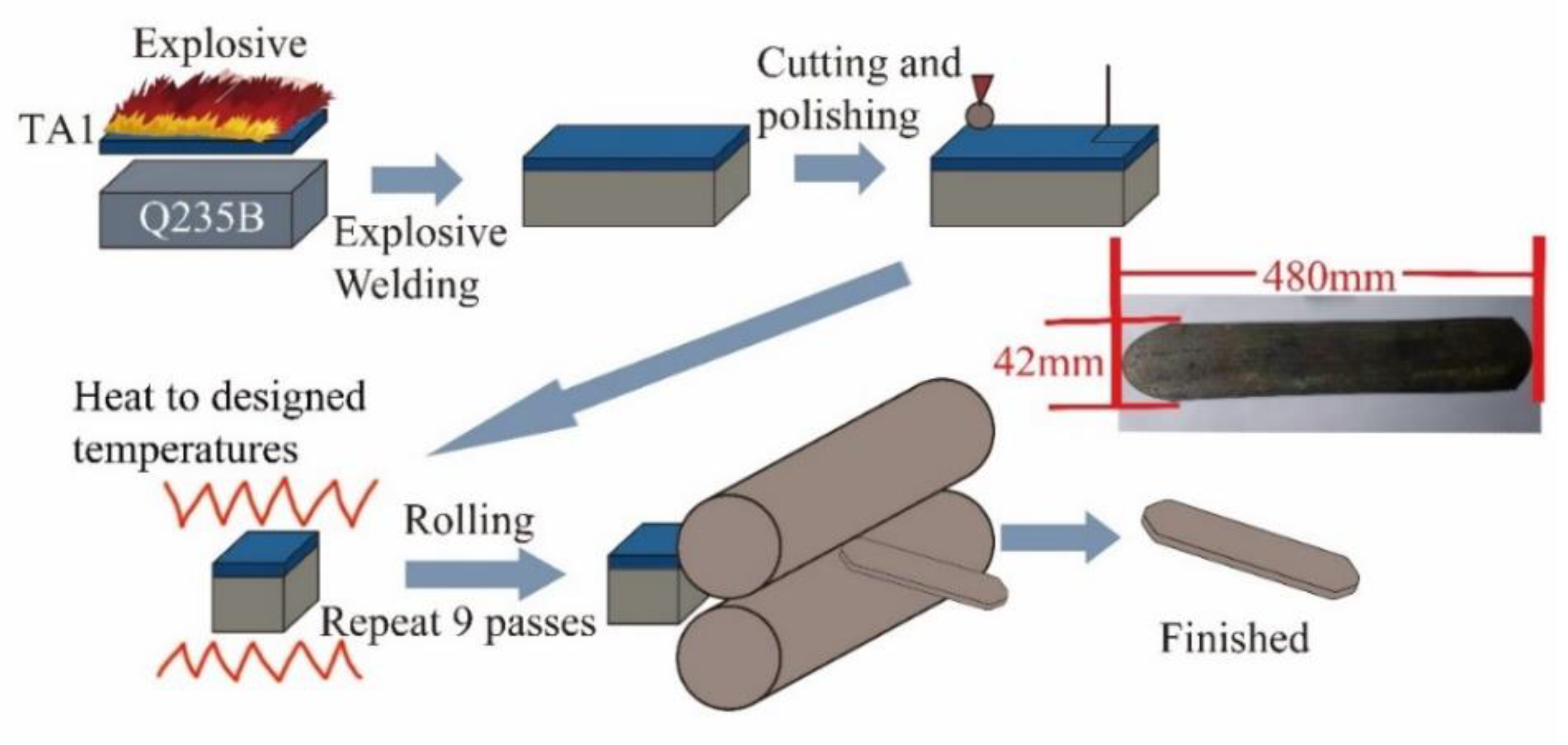
2.1. Raw Materials and Multi-Pass Rolling

The 17-mm-thick carbon steel plate (Q235B: C-0.18%; Mn-0.17%; Si-0.13%; S-0.017%; P-0.018%; Fe-Bal.) and 3-mm-thick commercial pure titanium sheet (TA1: Fe-0.023%; C-0.0024%; Ti-Bal.) were used as the raw materials for explosion welding. The explosion welded TA1/Q235B composite plates with a 2000 mm × 1000 mm × 20 mm size were prepared by Hunan Phohom New Material Technology Co., Ltd. (Changsha, China). The flyer plate (TA1) and base plate (Q235B) were placed parallel to the ground and the explosive was spread over the flyer plate. An emulsion explosive was selected and the explosive process follows the Jones–Wilkins–Lee (JWL) equation as Equation (1), as shown [23].
p = A ( 1 ω R 1 V ) e R 1 V + B ( 1 ω R 2 V ) e R 2 V + ω E V
where A, B, R1, R2, ω are constants relating to JWL equation, E is the energy per volume, V is relative specific capacity and p is pressure. Moreover, D (the detonation velocity) and ρ0 (the density of explosive) are physical parameters relating to emulsion explosive. Before the explosive welding experiment, according to the physical parameters of the explosive and the characteristics of the flyer plate and base plate, the JWL equation was simulated and optimized by computer. By adjusting the constants of the JWL equation, the appropriate explosion equation was obtained, and then the explosive welding experiment was carried out. The relevant parameters of the JWL equation and the physical parameters are shown in Table 1.
The preparation process of the TA1/Q235B sheets is shown in Figure 1. The size of explosive welded TA1/Q235B plates is 1000 mm × 2000 mm × 20 mm (3-mm-thick TA1 plate and 17-mm-thick Q235B plate). The sample with a size of 40 mm × 50 mm × 20 mm was cut from the center of the explosive welded TA1/Q235B composite plate with wire-electrode cutting. Then the samples were hot rolled at the temperatures of 1003 K, 1053 K and 1103 K, respectively. The rolling direction was consistent with the explosive direction. After nine passes of hot rolling, the TA1/Q235B sheets were obtained. The thicknesses and reduction of TA1 and Q235B before and after hot rolling are shown in Table 2.

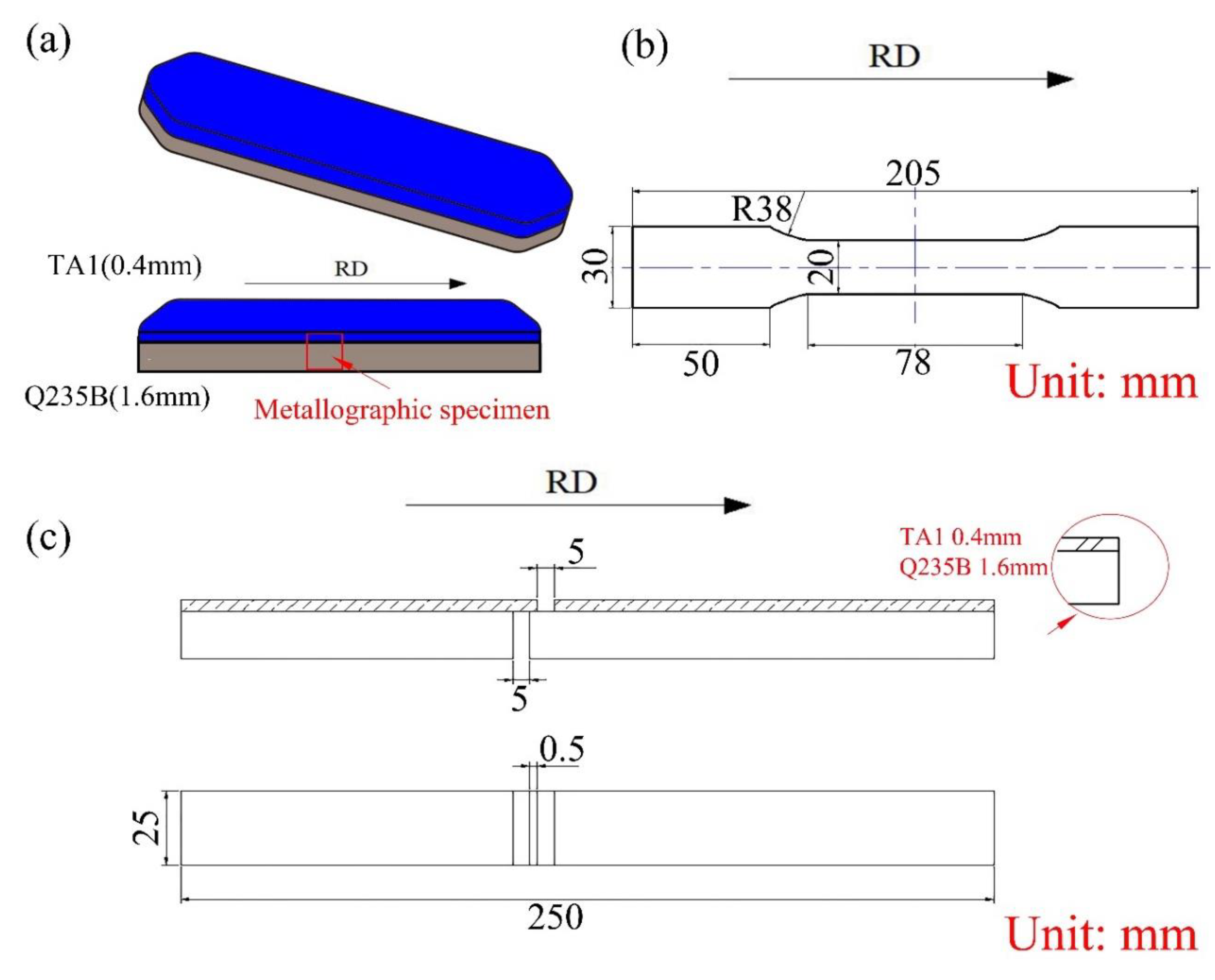
2.2. Microstructure and Mechanical Properties

The metallographic samples were parallel to the rolling direction (as Figure 2a shown), and examined with an optical microscope (OM, 4XC-II, Shanghai Optics Instrument Factory inc., Shanghai, China). The interface microstructure and tensile fracture morphology are observed on scanning electron microscopy (SEM, QUANTA-200, FEI inc., Hillsboro, OR, USA). The EBSD analysis is performed on a scanning electron microscope (SEM, SIRION 200, FEI inc., Hillsboro, OR, USA) equipped with an electron backscatter diffraction (EBSD) analyzer (XM4-Hikari, EDAX inc., Mahwah, NJ, USA). The accelerating voltage was 20 kV, working distance was 10 mm, and the step size of data acquisition was 100 nm. The element distributions near the interface are analyzed with energy dispersive spectroscopy (EDS, GENESIS60S, EDAX inc., Mahwah, NJ, USA) and electron probe micro-analysis (EPMA, JXA-8230, JEOL Ltd., Tokyo, Japan), respectively. The surfaces in both the TA1 and Q235B were peeled with a mechanical method and characterized by X-ray diffraction (XRD, D/Max 2500, Rigaku inc., Tokyo, Japan), using Cu Kα radiation scanning range from 30° to 90° at a step size of 0.02°.
The microhardness tests was performed at a Vickers hardness tester (200HVS-5, Huayin inc., Shandong, China), the load was 19.61 N and the holding time was 10 s. The tensile shear tests and tensile tests were repeated three times on the MTS-810 test machine (MTS inc., Eden Prairie, MN, USA) at a constant strain rate of 2.5 × 10⁻³ s−1 at room temperature (298 K). Moreover, the tensile direction was parallel to the rolling direction. The size of tensile specimen and the shear specimens (GB/T6396-2008 standard) are shown in Figure 2b,c and the shear strength was calculated by Equation (2).
τ = F b d
where F is the applied peak force, b is the notches distance and d is the bonding width of the specimen.

3. Results and Discussion

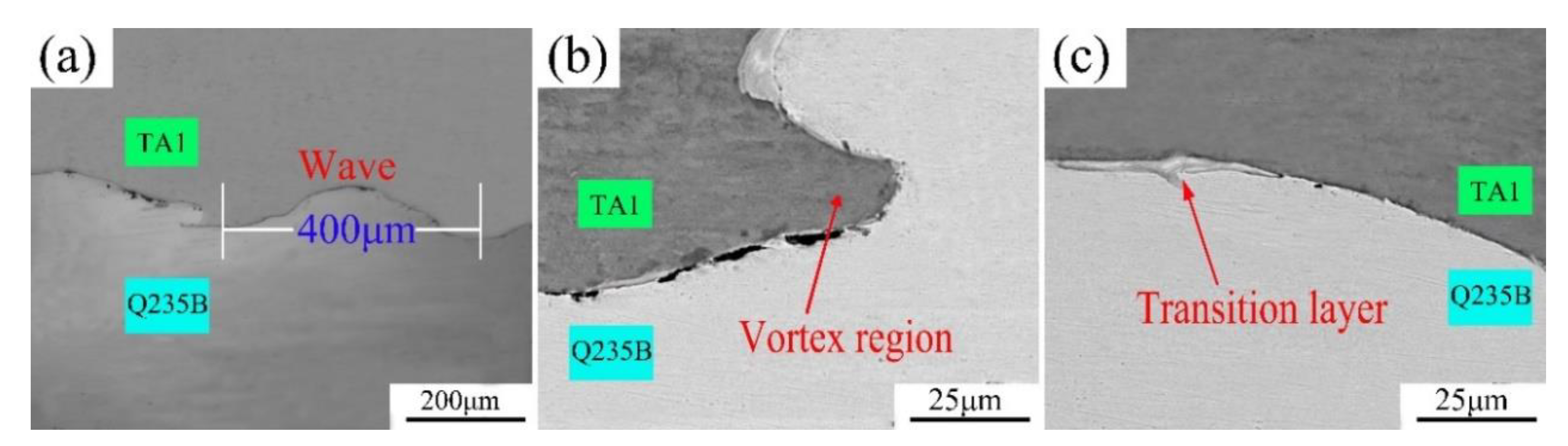
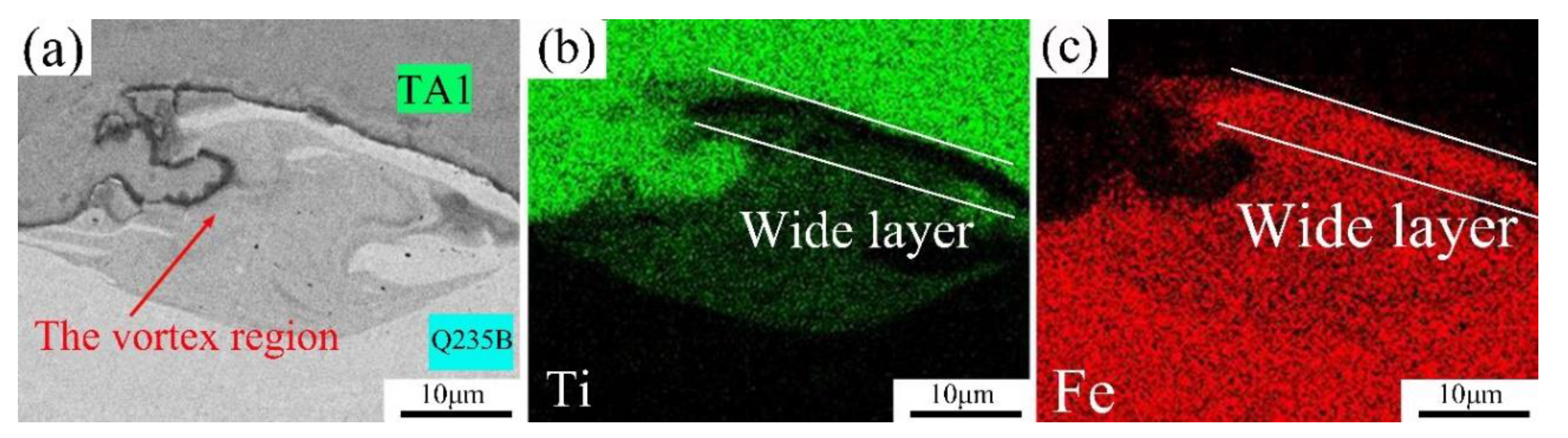
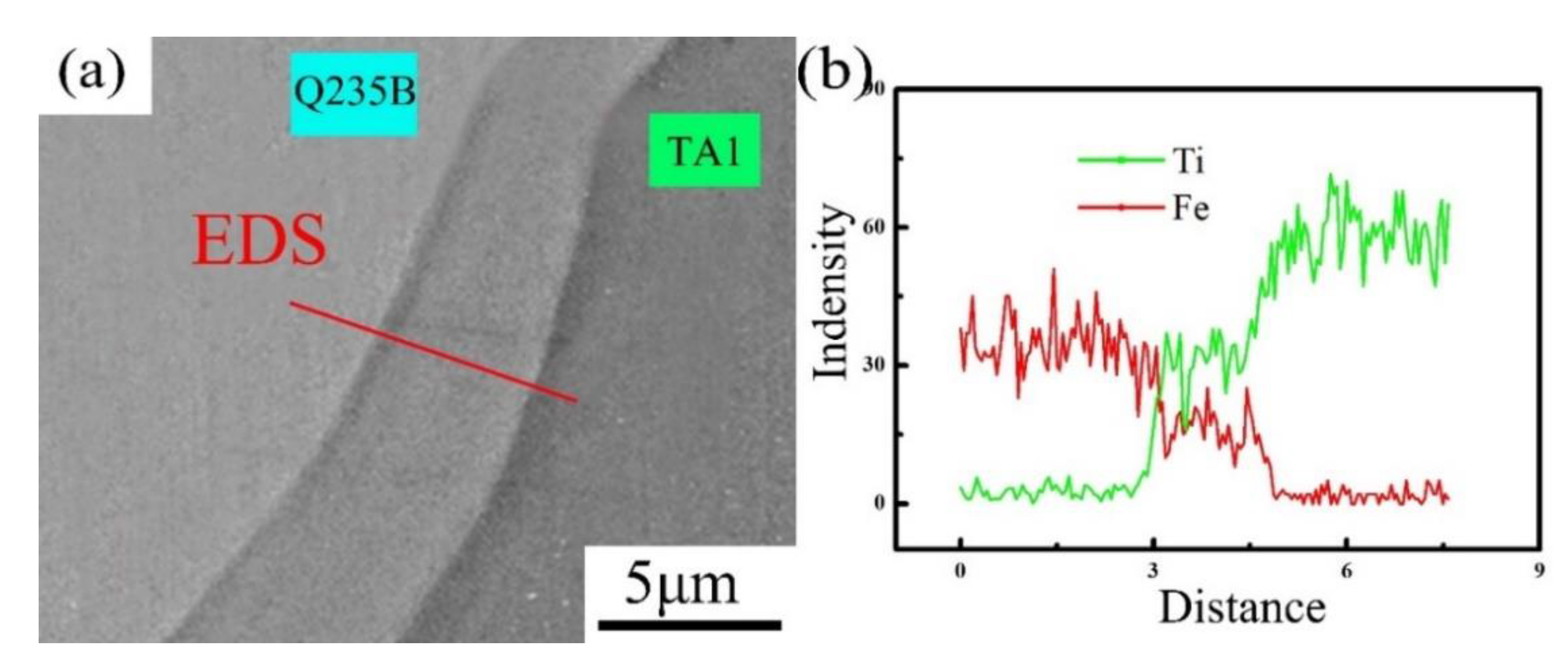
3.1. The Interface Microstructure of the Explosive Welded Plate

The typical interface microstructure of explosive welded TA1/Q235B composite plate is shown in Figure 3. It exhibits a typical periodic wave and the wavelength is about 400 μm (Figure 3a). The wave interfaces of the TA1/Q235B composite plate are divided into two categories: The vortex region is shown in Figure 3b and the transition layer as shown in Figure 3c. The wave expands along the effective bonding area of titanium and steel hinders crack propagation, which is an ideal microstructure of a welded joint [24]. The vortex region is composed of titanium and steel, and the transition layer is composed of compounds [25,26].
Figure 4a shows the details of vortex region at higher magnifications. The Ti and Fe element distributions measured by EDS mapping are displayed in Figure 4b,c, respectively. The Ti element is marked in green, and the red represents Fe element. It can be seen that the vortex region is a mixture of the two melted elements. The segregation of Fe (red) can be observed in the center of the melted vortex region, while Ti (green) is uniformly distributed in the red areas (Fe element). In addition, a wide red layer can be found in the crest, revealing the liquid steel flow from the high-pressure part to the low-pressure part. When titanium and carbon steel collide at high temperatures, pressures and speed, the accumulated heat does not have enough time to transfer outwards, causing the carbon steel and part of the titanium to melt at 1811 K. The most deformed steel melts first at the bonding interface, while the titanium does not directly melt. Only when more liquid steel flows to the titanium part and is mixed with the molten titanium can the vortex region be formed; this can explain why Fe dominates the central vortex region. Finally, under the action of relatively low wave-front pressure, the mixture of liquid steel and titanium accumulates gradually and flows towards the vortex region along the direction of the wave crest.
Another interface is a transition layer. As seen from Figure 5a, the large proportion of microscopic interface is widely distributed at the joint surface of the two metals. They tend to present behind the waveform. The energy dispersive spectroscopy (EDS) element line distribution in Figure 5b also shows the concentration gradient distributions of the two elements in the transition layer, indicating that the diffusion of titanium and carbon steel occurred in the transition layer. Additionally, because the pressure behind the wave is lower than at the peak, the metal in the transition layer is less likely to melt compared to the vortex region. When the two metals explosive welding, the heat generated by the collision is difficult to spread and accumulated at the back of the wave [27]. Although the metal in the transition layer did not melt, high temperature and friction region during the explosion were caused by collision, more importantly, which also caused the atoms of two metals to diffuse rapidly, creating a concentration gradient.

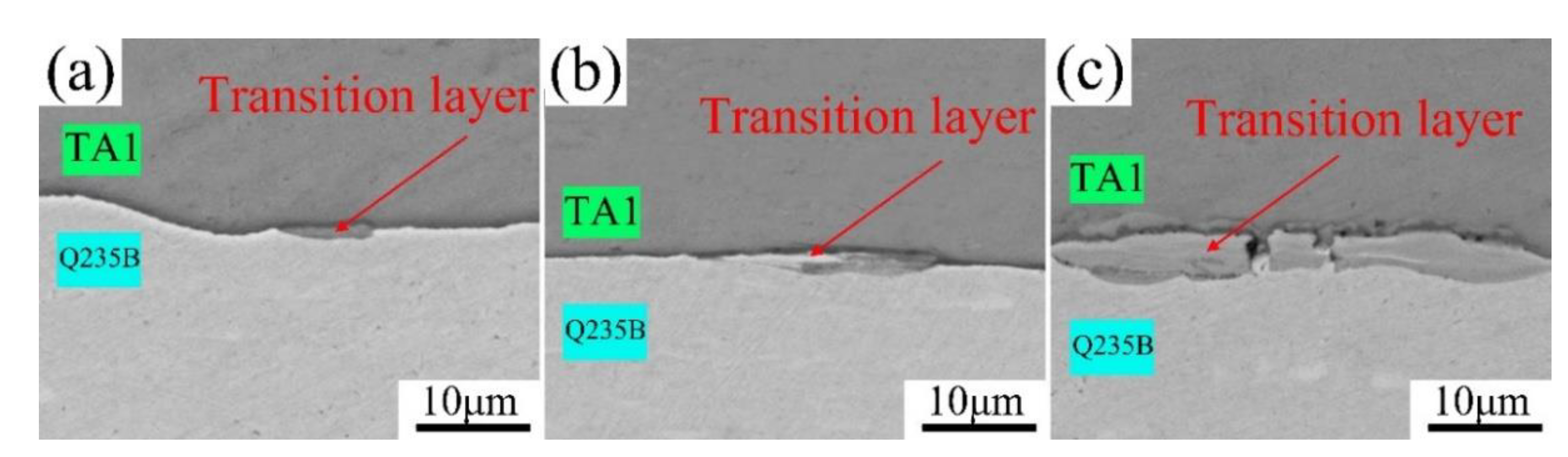
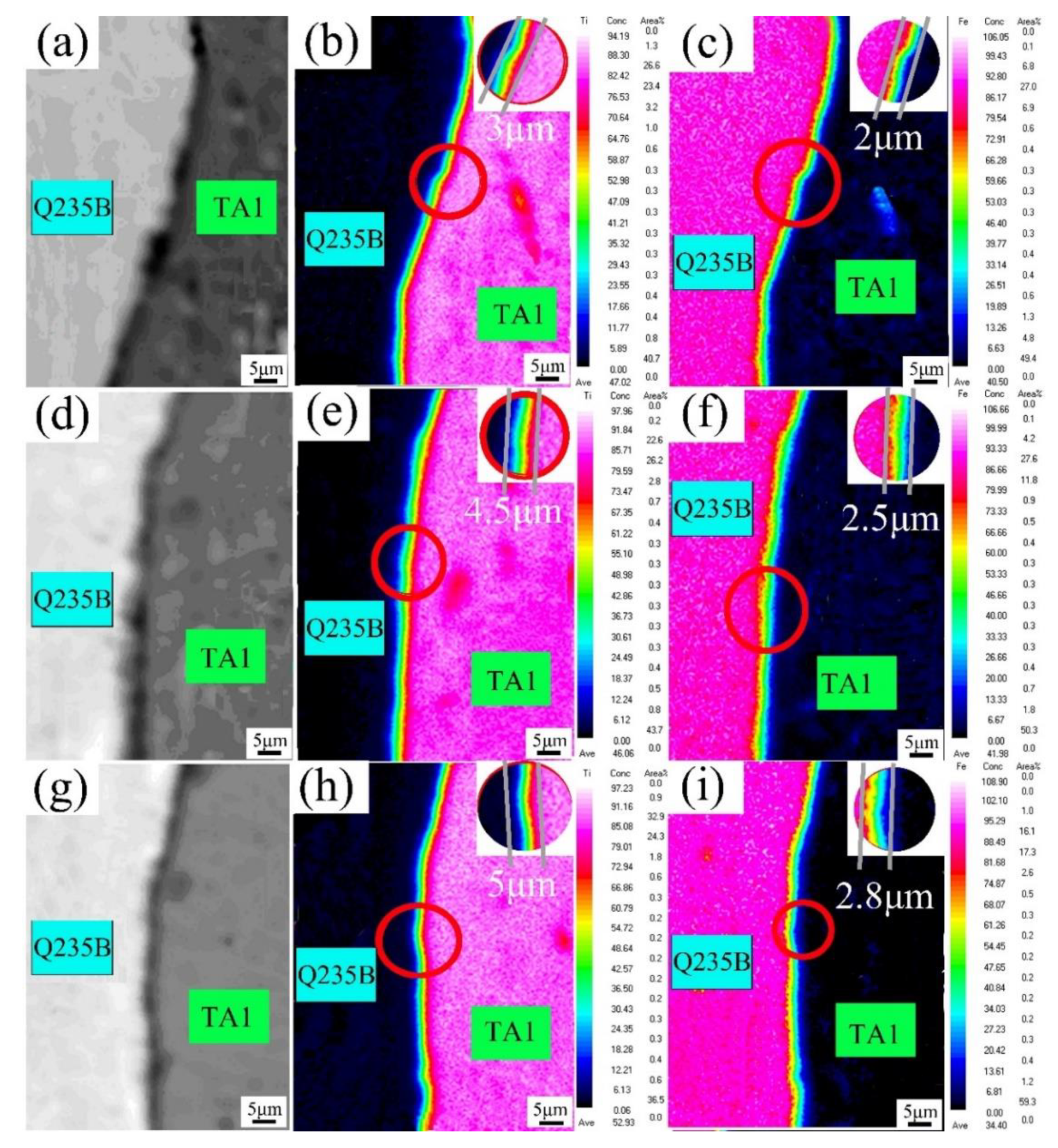
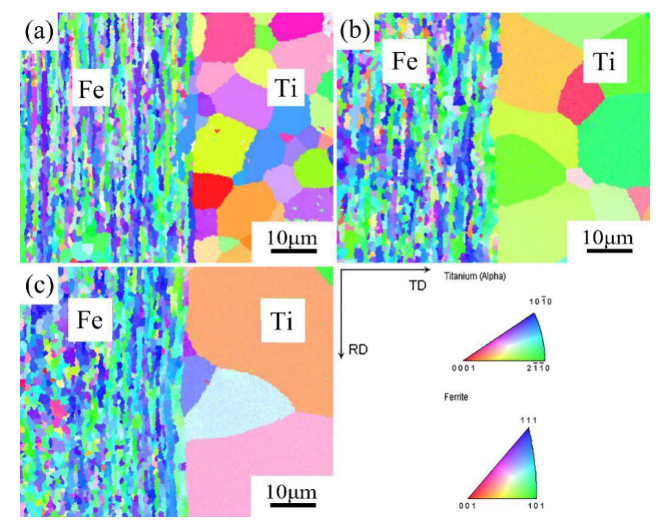
3.2. The Interfacial Microstructure of Hot-Rolled Sheets at Different Temperatures

The interface SEM microstructure of TA1/Q235B hot rolled sheets at different temperatures (1003 K, 1053 K and 1103 K) is shown in Figure 6. The vortex region disappears after hot rolling, and the interfacial is straight linearity. The transition layer is obvious. With the increases of rolling temperature, the width of transition layer increases from 3 μm (1003 K) to 4.5 μm (1053 K), and finally reaches 5 μm at 1103 K.
The TA1 layer and Q235B layer of the 1103 K hot-rolled composite sheet were separated by a mechanical method, and each of the two separated surfaces were tested by XRD. Figure 7 shows the XRD patterns of the two surfaces. It indicates that the interfacial compounds are primarily TiC and FeTi, and Ti mainly exists in the form of α-Ti rather than β-Ti, because the rolling temperature is not high enough to reach the phase transition temperature. The TiC and FeTi compounds are high-temperatures phases, which have relatively high hardness and low ductility. In addition, the FeTi distributes mainly in the carbon steel side, while TiC distributes on both sides. When the rolling temperature is lower than the phase transition temperature (1155 K) of titanium, the solid solubility of Fe in α-Ti is lower than that of Ti in Fe; therefore, Ti is easier to diffuse into Fe. During cooling after rolling, the FeTi intermetallic compound is formed in the Q235B layer. Due to the strong combining capacity of Ti and C, TiC compounds are easily formed at the interface.
The Figure 8 shows the distribution of C element in the TA1/Q235B interface. The thickness of the C element gathering region decreases from 5 μm at 1003 K to 2 μm at 1103 K. With the increase of rolling temperature, the distribution of the C element gathering region shows a substantial decrease along with the transition layer. At 1003 K, the diffusion of Ti in Q235B is very slow, and the TiC is formed preferentially at the interface, which hinders the grain boundary diffusion of Ti element and delays the formation of FeTi intermetallic compounds. Due to the high temperature and inhibition effect on carbides TiC [19], the amount of FeTi increases and that of TiC decreases, when the rolling temperature rises to 1103 K.
Figure 9 shows the EPMA element distribution of Ti and Fe in the interface of hot-rolling TA1/Q235B sheets at different temperatures. It can be seen that the interface of the two metals indicates the element concentration gradient of Ti and Fe. From the Ti distribution maps in Figure 9b,e,h, it can be found that titanium diffuses to 3 μm, 4.5 μm, and 5 μm to the Q235B when the rolling temperature is 1003 K, 1053 K, and 1103 K, respectively, while in the Fe element distribution map from Figure 9c,f,i, Fe diffuses less than 3 μm to the titanium owing to the titanium diffusion coefficient in steel is much larger than that of Fe in Ti [28,29].
The composition of diffusion layers are two different interfacial compounds, the carbide TiC forms earlier, and FeTi forms later. The main factor affecting the composition of TA1/Q235B composite plate is the carbide TiC and the interface intermetallic FeTi. In addition, the growth rate of interfacial compounds varies from the rolling conditions. Figure 8 and Figure 9 show that TiC layer is always thicker than the FeTi layer, which is attributed to the segregation of C element in the transition layer and it distributes linearly along the bonding interface of the Q235B. Atoms can spread along the grain interface, and the interface of Q235B provides a rapid diffusion channel for C and Ti atoms [30], so TiC generates more rapidly than FeTi.
The EBSD IPF mapping of TA1/Q235B sheets hot rolled at different temperatures is shown in Figure 10. The size of the grain gradually increases with the increasing rolling temperatures both in the TA1 and Q235B. In the Q235B, the grain is pulled into strips because of hot rolling, and the recrystallization of the grain occurs at a relatively high temperature [31]. While the grain grows from about 10 μm in 1003 K to about 30 μm in 1153 K in the TA1. In addition, there are some new grains generated due to the breakage and refinement of the original grains.

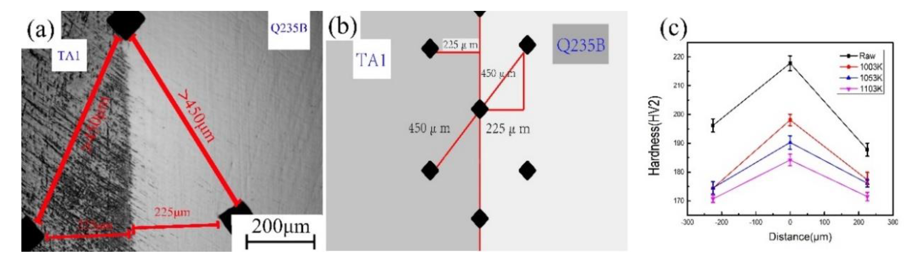
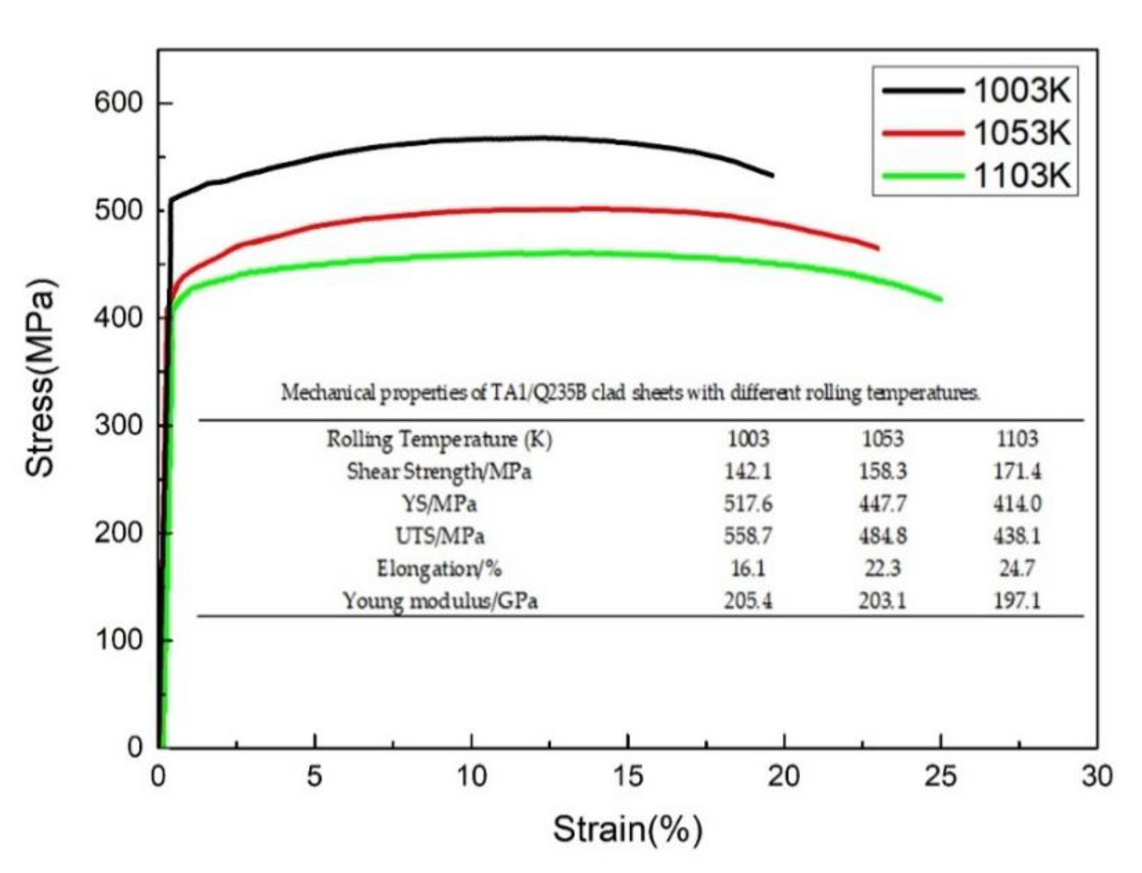
3.3. Mechanical Properties of TA1/Q235B Sheets Hot-Rolled at Different Temperatures

Figure 11 shows the microhardness and test schematic of explosive welding plates and hot-rolled sheets at different temperatures. Since the thickness of the sheet is only 2 mm after rolling, it is difficult to test the hardness gradient along a straight line, and to ensure that the adjacent test points are far enough so the test method as shown in Figure 11a,b is adopted. The microhardness of matrix metals is measured at the distance of 225 μm near the bonding interface, as shown in Figure 11b. Assuming that the interface bonding is the origin, the direction from the interface to Q235B side is positive. TA1, Q235B and the interface are tested five times, and the results are averaged. The interface microhardness distribution is shown in Figure 11c. The microhardness of the explosive welded plate is higher than that of the rolled sheets and the hardness of the matrix, and the interface decreases with the increase of the rolling temperature. The microhardness of the interface is higher than that of the matrix. The maximum interface microhardness is 217.8 HV at the explosive welded plate, with an increase of rolling temperature, which is gradually decreases to 184.2 HV. When the rolling temperature rises, the change of interface microhardness is related to the amount of TiC (as shown in Figure 8), while the decrease of TA1 and Q235B matrix microhardness is related to the recrystallization grain size (as shown in Figure 10).
Shear strengths, yield strength (YS), ultimate tensile strength (UTS), maximum elongation and Young’s modulus of rolled sheets under different temperatures are shown in Figure 12. With the increase of the rolling temperature from 1003 K to 1103 K, the shear strength of the composite sheet increases from 142.1 MPa to 171.4 MPa. The interface shear strength of the TA1/Q235 composite sheet is affected mainly by the interface brittle compounds. It can be seen from Figure 8 that the amount of the C element in the transition layer decreases when rolling temperatures rises, it means the amount of brittle TiC decreases with the increase of rolling temperature. Hence, the formation of brittle carbides in TiC may suppress by the increasing rolling temperature, and the shear strength improved with the disappearance of brittle compounds TiC at a relatively high rolling temperature.
The YS and UTS of hot rolled TA1/Q235 sheets decrease with the increase of rolling temperature. After rolling at 1003 K, the maximum YS and UTS of the hot rolled sheet are 517.6 MPa and 558.7 MPa, respectively. The sheet rolled at 1103 K shows lower yield strength (414.0 MPa) and ultimate tensile strength (438.1 MPa) than that rolled at 1003 K and 1053 K. The lower strength of 1103 K rolled sheet is due to the increase of recrystallization in titanium and carbon steel matrix at higher temperature (as shown in Figure 10). The increase of recrystallization also leads to a gradual increase in elongation. The Figure 12 also shows that the rolling temperature has little influence on the Young’s modulus of the sheet, and when rolling temperature rises from 1003 K to 1103 K, while the Young’s modulus of the sheet does not change significantly and only decreases slightly.
Figure 13 shows the macroscopic morphology of sheets rolled at different temperatures after tensile fractured. It can be seen that titanium and carbon steel are separated near the fracture surface. During the tensile test, the brittle compounds TiC and FeTi in the bonding interface fractured firstly. Subsequently, the fracture occurred in the matrix metals. Figure 14 shows the SEM fracture morphology after tensile fracture of samples rolled at different temperatures. It is obvious that interfacial fractures of the composite sheet rolled at 1003 K is small, and the extent of interfacial fractures increases with the increasing rolling temperature. It illustrates that the interfacial compounds layer causes the cracks to initiate in the composite sheets, and crack propagation is more serious with the thicker interfacial compound layer. It can be seen from Figure 14d–f that the fracture profiles of titanium at different rolling temperatures are similar in fracture characteristics. The fracture profile of the TA1 plate includes cleavage fractures, while the fracture profile of carbon steel is a dimple fracture. As shown in Figure 14g–i, the depth, size, and proportion of the dimple increased with the increase in rolling temperature, and the plasticity of the composite sheets increased simultaneously [32,33]. The more in-depth, more extensive, as well as larger proportion of dimple fractures exist on the carbon steel side of the composite sheet at 1103 K, which is related to the increase in plasticity after proper heating [34]. Because of the appearance of both dimples and cleavage planes in the rolled composite sheet, it infers that the fractures of TA1/Q235B composite sheets are a mixed-mode of ductile and brittle fractures.

4. Conclusions

The 2-mm TA1/Q235B composite sheets (TA1 is 0.4 mm and Q235B is 1.6 mm) are fabricated through explosive welding and nine passes of hot rolling at different temperatures. The microstructure and mechanical properties were studied and the following conclusions were drawn:
(1)
The vortex region and the transition layer microstructures are formed in the TA1/Q235B explosive welded plate. After hot rolling, only the transition layer exists in the bonding surfaces.
(2)
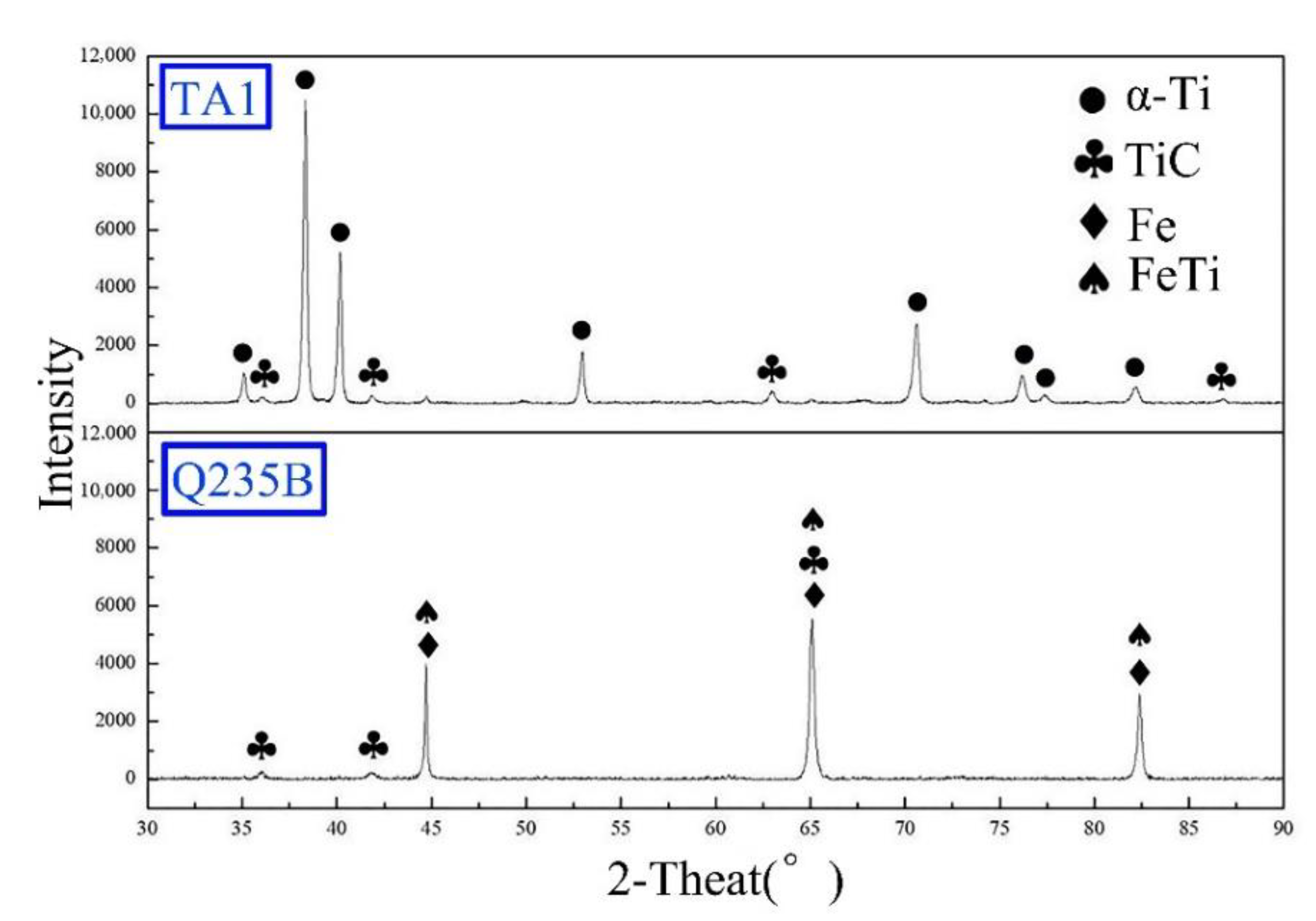
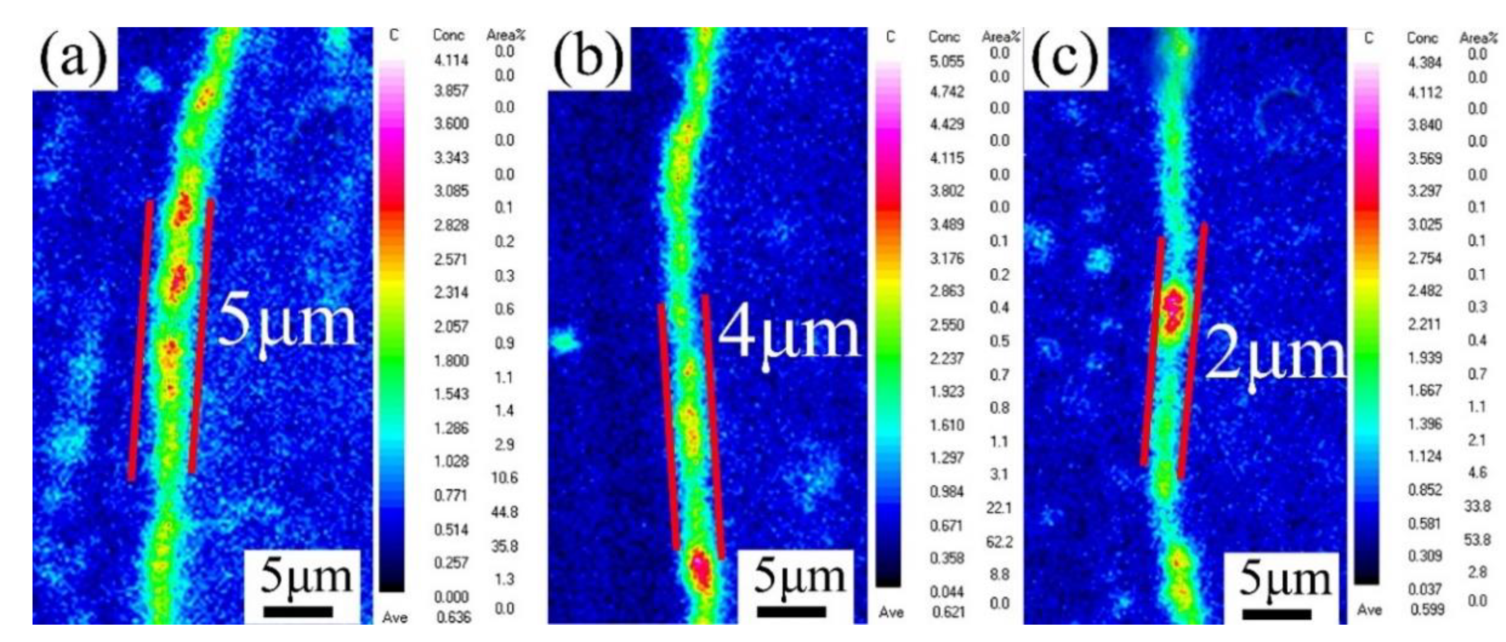
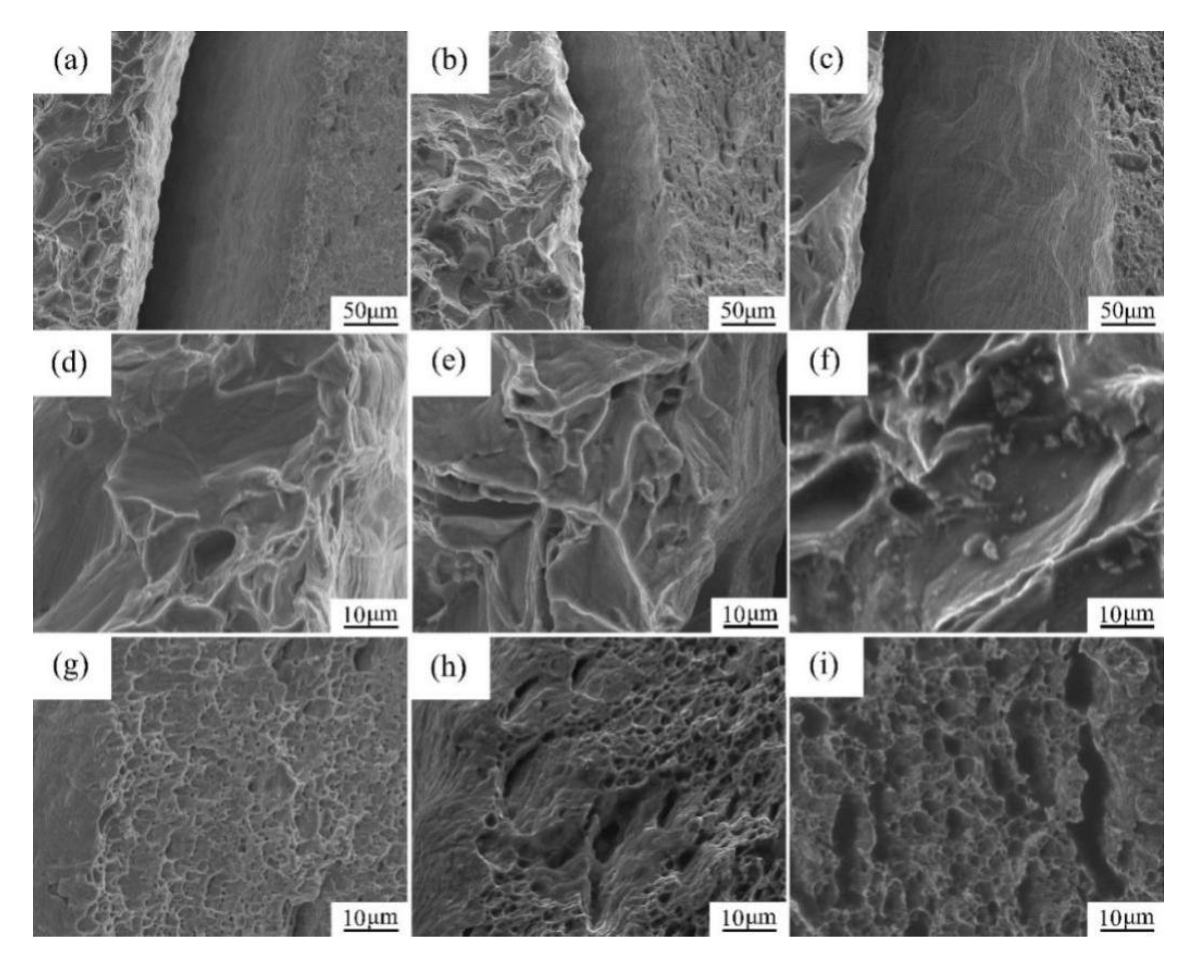
The thickness of transition layer increases with the increase of rolling temperatures. The component of the transition layer is α-Ti, TiC, Fe, and FeTi. In addition, the fracture is a mixed-mode of ductile and brittle fractures, which mainly occurred in interface layer.
(3)
Due to fragile and hard interfacial compounds, the microhardness of the explosive plate is higher than that of hot rolled sheets. High temperatures reduce the proportion of brittle TiC compounds, resulting in an increment of interface shear strength. However, due to the increase of recrystallization degree of TA1 and Q235B at a high temperature, the yield strength and tensile strength of the sheet decreased. Furthermore, when the rolling temperature rises, the elongation increases, while the Young’s modulus shows little change.

Author Contributions

H.L. and X.L. conceived and designed the experiments; L.C. performed the experiments; W.Z. and C.W. analyzed the data; Z.Z. contributed reagents/materials/analysis tools; C.Z. wrote the paper. All authors have read and agreed to the published version of the manuscript.

Funding

This research was funded by the Fundamental Research Fund for the Central Universities of Central South University (Grant Number: 502041002) and the Open Sharing Fund for the Large-scale Instruments and Equipment of Central South University.

Acknowledgments

This research was financially supported by the Fundamental Research Fund for the Central Universities (Changsha, China) and the Open Sharing Fund for the Large-scale Instruments and Equipment of Central South University. The authors are grateful to the Hunan Phohom New Material Technology Co., Ltd for the support in explosive welding experiment.

Conflicts of Interest

The authors declare no conflict of interest.

References

  1. Nishida, M.; Chiba, A.; Honda, Y.; Hirazumi, J.-I.; Horikiri, K. Electron Microscopy Studies of Bonding Interface in Explosively Welded Ti/Steel Clads. ISIJ Int. 1995, 35, 217–219. [Google Scholar] [CrossRef] [Green Version]
  2. Wachowski, M.; Sniezek, L.; Szachogluchowicz, I.; Kosturek, R.; Plocinski, T. Microstructure and fatigue life of Cp-Ti/316L bimetallic joints obtained by means of explosive welding. Bull. Pol. Acad. of Sci. Tech. Sci. 2018, 66, 925–933. [Google Scholar]
  3. Li, Y.; Liu, C.; Yu, H.; Zhao, F.; Wu, Z. Numerical Simulation of Ti/Al Bimetal Composite Fabricated by Explosive Welding. Metals 2017, 7, 407. [Google Scholar] [CrossRef] [Green Version]
  4. Ning, J.; Zhang, L.; Xie, M.-X.; Yang, H.-X.; Yin, X.-Q.; Zhang, J.-X. Microstructure and property inhomogeneity investigations of bonded Zr/Ti/steel trimetallic sheet fabricated by explosive welding. J. Alloys Compd. 2017, 698, 835–851. [Google Scholar] [CrossRef]
  5. Carvalho, G.; Galvão, I.; Mendes, R.; Leal, R.; Loureiro, A. Aluminum-to-Steel Cladding by Explosive Welding. Metals 2020, 10, 1062. [Google Scholar] [CrossRef]
  6. Yu, C.; Xiao, H.; Yu, H.; Qi, Z.; Xu, C. Mechanical properties and interfacial structure of hot-roll bonding TA2/Q235B plate using DT4 interlayer. Mater. Sci. Eng. A 2017, 695, 120–125. [Google Scholar] [CrossRef]
  7. Sun, Z.; Shi, C.; Wu, X.; Shi, H. Comprehensive investigation of effect of the charge thickness and stand-off gap on interface characteristics of explosively welded TA2 and Q235B. Compos. Interfaces 2020, 27, 977–993. [Google Scholar] [CrossRef]
  8. Paul, H.; Chulist, R.; Bobrowski, P.; Perzynski, K.; Madej, L.; Mania, I.; Miszczyk, M.M.; Cios, G. Microstructure and properties of the interfacial region in explosively welded and post-annealed titanium-copper sheets. Mater. Charact. 2020, 167, 110520. [Google Scholar] [CrossRef]
  9. Bina, M.H.; Dehghani, F.; Salimi, M. Effect of heat treatment on bonding interface in explosive welded copper/stainless steel. Mater. Des. 2013, 45, 504–509. [Google Scholar] [CrossRef]
  10. Chen, Z.; Wang, D.; Cao, X.; Yang, W.; Wang, W. Influence of multi-pass rolling and subsequent annealing on the interface microstructure and mechanical properties of the explosive welding Mg/Al composite plates. Mater. Sci. Eng. A 2018, 723, 97–108. [Google Scholar] [CrossRef]
  11. Lysak, V.; Kuzmin, S.V. Energy balance during explosive welding. J. Mater. Process. Technol. 2015, 222, 356–364. [Google Scholar] [CrossRef]
  12. Vieille, B.; Casado, V.M.; Bouvet, C. About the impact behavior of woven-ply carbon fiber-reinforced thermoplastic- and thermosetting-composites: A comparative study. Compos. Struct. 2013, 101, 9–21. [Google Scholar] [CrossRef] [Green Version]
  13. Pereira, D.; Oliveira, J.P.; Pardal, T.; Miranda, R.M.; Santos, T.G. Magnetic pulse welding: Machine optimisation for aluminium tubular joints production. Sci. Technol. Weld. Join. 2018, 23, 172–179. [Google Scholar] [CrossRef]
  14. Ha, J.S.; Hong, S. Deformation and fracture of Ti/439 stainless steel clad composite at intermediate temperatures. Mater. Sci. Eng. A 2016, 651, 805–809. [Google Scholar] [CrossRef]
  15. Liu, J.; Cai, W.; Liu, L.; Han, J.; Liu, J. Investigation of interfacial structure and mechanical properties of titanium clad steel sheets prepared by a brazing-rolling process. Mater. Sci. Eng. A 2017, 703, 386–398. [Google Scholar] [CrossRef]
  16. Cui, Y.; Liu, D.; Fan, M.Y.; Deng, G.P.; Sun, L.X.; Zhang, Y.; Chen, D.; Zhang, Z.W. Microstructure and mechanical properties of TA1/3A21 composite plate fabricated via explosive welding. Mater. Sci. Technol. 2020, 36, 425–433. [Google Scholar] [CrossRef]
  17. Song, J.; Kostka, A.; Veehmayer, M.; Raabe, D. Hierarchical microstructure of explosive joints: Example of titanium to steel cladding. Mater. Sci. Eng. A 2011, 528, 2641–2647. [Google Scholar] [CrossRef]
  18. Jiang, H.-T.; Yan, X.-Q.; Liu, J.-X.; Duan, X.-G. Effect of heat treatment on microstructure and mechanical property of Ti–steel explosive-rolling clad plate. Trans. Nonferrous Met. Soc. China 2014, 24, 697–704. [Google Scholar] [CrossRef]
  19. Jin, Y.X.; Zeng, S.Y.; Wang, H.W. Changes of carbides morphology in the alloy Ti15Al7C during heat treatment. Rare Metal Mater. Eng. 2002, 31, 358–362. [Google Scholar]
  20. Chu, Q.; Zhang, M.; Li, J.; Yan, C. Experimental and numerical investigation of microstructure and mechanical behavior of titanium/steel interfaces prepared by explosive welding. Mater. Sci. Eng. A 2017, 689, 323–331. [Google Scholar] [CrossRef]
  21. Li, B.; Chen, Z.; He, W.; Wang, P.; Lin, J.; Wang, Y.; Peng, L.; Li, J.; Liu, Q. Effect of interlayer material and rolling temperature on microstructures and mechanical properties of titanium/steel clad plates. Mater. Sci. Eng. A 2019, 749, 241–248. [Google Scholar] [CrossRef]
  22. Arisova, V.N.; Gurevich, L.M.; Trudov, A.F.; Serov, A.G.; Kharlamov, V.G. Structure Formation in the Zones of Joints Obtained by Explosion Welding with Subsequent Rolling of a Five-Layer Titanium-Steel Composite. Metals 2019, 63, 96–104. [Google Scholar] [CrossRef]
  23. Sun, Z.; Shi, C.-G.; Shi, H.; Li, F.; Gao, L.; Wang, G. Comparative study of energy distribution and interface morphology in parallel and double vertical explosive welding by numerical simulations and experiments. Mater. Des. 2020, 195, 109027. [Google Scholar] [CrossRef]
  24. Acarer, M.; Gülenç, B.; Fındık, F. Investigation of explosive welding parameters and their effects on microhardness and shear strength. Mater. Des. 2003, 24, 659–664. [Google Scholar] [CrossRef]
  25. Zhang, H.; Jiao, K.X.; Zhang, J.L.; Liu, J. Comparisons of the microstructures and micro-mechanical properties of copper/steel explosive-bonded wave interfaces. Mater. Sci. Eng. A 2019, 756, 430–441. [Google Scholar] [CrossRef]
  26. Wronka, B. Testing of explosive welding and welded joints: Joint mechanism and properties of explosive welded joints. J. Mater. Sci. 2010, 45, 4078–4083. [Google Scholar] [CrossRef]
  27. Qin, L.; Wang, J.; Wu, Q.; Guo, X.; Tao, J. In-situ observation of crack initiation and propagation in Ti/Al composite laminates during tensile test. J. Alloys Compd. 2017, 712, 69–75. [Google Scholar] [CrossRef]
  28. Kundu, S.; Chatterjee, S. Effect of bonding temperature on interface microstructure and properties of titanium–304 stainless steel diffusion bonded joints with Ni interlayer. Mater. Sci. Technol. 2006, 22, 1201–1207. [Google Scholar] [CrossRef]
  29. Klugkist, P.; Herzig, C. Tracer diffusion of titanium in α-iron. Phys. Status Solidi 2010, 148, 413–421. [Google Scholar] [CrossRef]
  30. Sam, S.; Kundu, S.; Chatterjee, S. Diffusion bonding of titanium alloy to micro-duplex stainless steel using a nickel alloy interlayer: Interface microstructure and strength properties. Mater. Des. 2012, 40, 237–244. [Google Scholar] [CrossRef]
  31. Kahraman, N.; Gülenç, B.; Findik, F. Joining of titanium/stainless steel by explosive welding and effect on interface. J. Mater. Process. Technol. 2005, 169, 127–133. [Google Scholar] [CrossRef]
  32. Blach, J.; Falat, L.; Ševc, P. Fracture characteristics of thermally exposed 9Cr–1Mo steel after tensile and impact testing at room temperature. Eng. Fail. Anal. 2009, 16, 1397–1403. [Google Scholar] [CrossRef]
  33. Xie, M.-X.; Zhang, L.-J.; Zhang, G.; Zhang, J.-X.; Bi, Z.-Y.; Li, P.-C. Microstructure and mechanical properties of CP-Ti/X65 bimetallic sheets fabricated by explosive welding and hot rolling. Mater. Des. 2015, 87, 181–197. [Google Scholar] [CrossRef]
  34. Rozumek, D.; Bański, R. Crack growth rate under cyclic bending in the explosively welded steel/titanium bimetals. Mater. Des. 2012, 38, 139–146. [Google Scholar] [CrossRef]
Figure 1. Schematic diagram of the preparation process of 2-mm-TA1/Q235B composite sheets.
Metals 10 01654 g001
Figure 2. Schematic diagrams of specimen for (a) metallographic specimen, (b) tensile test, and (c) tensile shear test.
Metals 10 01654 g002
Figure 3. (a) SEM of the TA1/Q235B interface: (b) the vortex region and (c) transition layer.
Metals 10 01654 g003
Figure 4. (a) SEM microstructure of melted vortex regions of TA1/Q235B welded plate (b) EDS map for Ti (Green) and (c) Fe (Red).
Metals 10 01654 g004
Figure 5. (a) SEM microstructure of transition layer, and (b) EDS element line distribution for Ti (Green) and Fe (Red) in transition layer of explosive welded TA1/Q235B plate.
Metals 10 01654 g005
Figure 6. Interface SEM microstructure of TA1/Q235B sheets hot-rolled at (a) 1003 K, (b) 1053 K, (c) 1103 K.
Metals 10 01654 g006
Figure 7. XRD patterns of both separation surfaces of TA1/Q235B hot rolled sheet.
Metals 10 01654 g007
Figure 8. Electron probe micro-analysis (EPMA) for C element distribution in the interface of TA1/Q235B hot-rolled sheets at the temperatures of (a) 1003 K (b) 1053 K (c) 1103 K.
Metals 10 01654 g008
Figure 9. Electron probe micro-analysis (EPMA) element distribution in the interface of TA1/Q235B sheets hot rolled at (ac) 1003 K, (df) 1053 K and (gi) 1103 K, (a,d,g) are microstructures, (b,e,h) are Ti elements and (c,f,i) are Fe elements.
Metals 10 01654 g009
Figure 10. EBSD Inverse pole figure (IPF) mapping of TA1/Q235B sheets hot rolled at the temperature of (a) 1003 K (b) 1053 K (c) 1103 K.
Metals 10 01654 g010
Figure 11. (a) Micrograph of microhardness test (b) schematic of microhardness test (c) microhardness of explosive welding plate and different temperatures rolled sheets.
Metals 10 01654 g011
Figure 12. The tensile stress-strain curves and mechanical properties of TA1/Q235B composite sheets at different rolling temperatures.
Metals 10 01654 g012
Figure 13. (a) The area of SEM of fracture profiles, (b) Macroscopic morphology of sheets rolled at different temperatures after tensile fracture.
Metals 10 01654 g013
Figure 14. SEM fracture morphology after tensile fracture of samples rolled at different temperatures: (a) 1003 K, (b) 1053 K, (c) 1103 K, (d,g) Ti and steel matrices in (a), (e,h) Ti and steel matrices in (b), (f,i) Ti and Steel matrices in (c).
Metals 10 01654 g014
Table 1. The parameters of the Jones–Wilkins–Lee (JWL) equation and physical parameters.
ParametersA (GPa)B (GPa)R1R2ωD (m/s)VE (kJ/m3)ρ0 (g/cm3)p (GPa)
Value8.6150.8183.7540.8070.01210015.252 × 1050.81.278
Table 2. The thickness and reduction of TA1/Q235B Sheets.
MaterialsThickness Before Rolling (mm)Thickness After Rolling (mm)Reduction (%)
TA130.486.7
Q235B171.690.6
Publisher’s Note: MDPI stays neutral with regard to jurisdictional claims in published maps and institutional affiliations.

