Article

Welded Construction Design of Transition Fittings from Metal Pipes to Plastic Pipes

Faculty of Engineering, Lucian Blaga University of Sibiu, 550024 Sibiu, Romania
*
Author to whom correspondence should be addressed.
Metals 2020, 10(9), 1231; https://doi.org/10.3390/met10091231
Submission received: 7 August 2020 / Revised: 7 September 2020 / Accepted: 11 September 2020 / Published: 13 September 2020
(This article belongs to the Special Issue Design of Welded Steel Structures)

Abstract

:
Transition type fittings are components often used in facilities where fluids are transported that allow the passage from a high density polyethylene (HDPE) pipe to a steel pipe. In the presented studies, four types of transition fittings were analyzed in the first stage. The four types of transition fittings are distinguished by the shape of their welded steel construction. The performed analyses took into account testing the behavior upon exposure to fatigue, measuring the HDPE hardness and applying the finite element method (FEM). As a result of these studies it was demonstrated that the form of the welded steel construction has a very great influence on the operating behavior of the transition fitting. Thus, a new transition fitting with a welded steel construction was designed. In this new type of transition fitting, an approximately 50% increase in resistance to fatigue stress, an approximately 90% reduction in stress in the part material and a reduction in the hardness of the material in HDPE pipes was obtained. The studies allow not only an improvement of the characteristics for these types of parts, but also the optimization of other types of steel-plastic joints.

1. Introduction

Metals and plastics are widely used in industrial applications, and the connection of a metal part with a plastic part is often necessary and important from a manufacturing point of view. Therefore, the combination of a metal material and a laser-assisted plastic material (LAMP) has been developed as an innovative direct laser joint, without adhesives or glue [1,2]. It has been demonstrated that the joining of metal and plastic materials through LAMP technology offers a high-strength nanostructural bonding through formation of an oxide film that has high reliability in various practical uses [3,4,5].
Also, for joining stainless steel plates with polyethylene terephthalate (PET) plastic plates, the tungsten inert gas (TIG) welding process is used. The analysis of the joints made by this welding process showed that the two plates were glued by the reaction of the PET carbonyl groups and the metallic element which allows the formation of chemical bonds that result in joints with significantly improved strengths [6,7].
The technological variant of laser welding of polyethylene terephthalate (PET) and titanium alloy Ti6Al4V was tested and it was shown that porosity always appears in the high temperature region of the formed joint due to the decomposition of PET. In addition, it was also found that a melted material bath is formed only in the PET layer and certain parameters of the welding technological process have significant effects on the fluid flow, which influences the heat transfer and, implicitly, the formation of the welded joint. Consequently, it is always necessary to adopt adequate technological parameters to when forming the joint in order to obtain a welded joint without defects [8,9].
A variant for joining carbon fiber reinforced plastics (CFRP) with titanium (Ti) alloy is laser technology. When applying this technology, the results indicated that fewer defects can be obtained on the surface of the titanium alloy and fewer bubbles inside the CFRP, provided a higher welding speed is adopted. The layer of material obtained in the joint was generated as a CTi0.42V1.58 phase due to the carburization of the titanium alloy [10,11].
The joining of different lightweight materials for the realization of lightweight multi-material structures is also a new technical solution in the manufacture of cars or other advanced vehicles [12]. Given that titanium alloys are characterized by high specific strength and good corrosion resistance, they can be a solution for the realization of aerospace and automotive industry equipment. However, titanium alloys are fairly expensive, so that with increasing requirements for lightweight structural materials, carbon fiber reinforced plastic (CFRP) with high specific strength and low density has gradually been considered as an alternative material in engineering applications [13,14]. In order to replace titanium alloys, in recent years CFRP/titanium alloy material joining technologies have been developed with applications in aircraft construction and certain automotive industry pats, in the aircraft and automotive subsectors. Thus, a high quality combination of CFRP and titanium alloy will not only provide an additional weight reduction but will also increase the application scope of these advanced materials [15,16].
A possible technology for joining thermoplastic and metallic materials is ultrasonic welding. The use of this joint technology seems to provide good results in practice, but the performance of such a joint is strongly influenced by the geometry of the microstructure of the metallic material in the piece. If a suitable geometry is adopted for the metal part, ultrasonic hot welding seems to be a fast, low-cost and reliable method to obtain hybrid plastic/metal products for electronics and other industrial applications [17,18].
A possible variant for optimizing the joining parameters of metals and plastics is the use of FEM, and the obtained results indicate that this approach can be easily used to optimize process conditions as well as to optimize the shape and size of welded joints [19]. At present, plastic deformation technologies have been applied to make joints between aluminum pipes and plastic pipes, but this solution can be applied only if these types of joints are subject to low mechanical stress [20,21].
The law of similarities between deep drawing and tube drawing with and without a floating mandrel, together with the entered real boundary conditions of the drawing process simulation, can represent a technical solution that can be applied in the case of joints between a piece of metal and a piece of plastic [22].
At present, a special problem that requires an optimal technical solution refers to the realization of fittings with the best possible characteristics and performance in operation, which will allow the assembly of plastic and steel pipes. These fittings have a welded steel construction in the structure that allows joining them with plastic pipes. The presence of the welded joint and, implicitly, of a heat affected zone (HAZ), requires the adoption of a certain design for the welded joint so that the heat in the HAZ influences as little as possible the characteristics of the plastic pipes. Under these conditions, studies have considered several variants of the welded construction of the fittings, aimed at the following aspects: analysis of the behavior at the fatigue stress of different transition fittings, the effect of the presence of heat from the HAZ in changing the hardness of plastics and modeling of different types of fittings by the finite element method (FEM). Following these analyzes, a fitting variant with a certain welded construction design and very good behavior in operation was proposed.

2. Materials and Methods

2.1. Materials

The structure of a transition fitting from a metal pipe to a plastic one includes the following types of material: the steel from which the metal pipes are made, the inner and outer bushes of the fitting, pipe made of high density polyethylene (HDPE) and any material added to form the welded joint.
The steel from which the inner bushings, outer bushings and the steel pipe were made was a steel used to make seamless pipes resistant to pressure and ambient temperature, with the P 235 TR 1 designation, in accordance with SREN 10025-4. The chemical composition of a liquid steel batch is presented in Table 1 and the mechanical characteristics in Table 2. Both the chemical composition (Table 1) and the mechanical properties (Table 2), are in accordance with those provided by the steel pipe manufacturer (TubeMFG, Zhangjiagang, China).
An electrode filler material with a E 50 4 B 4 2 H5 designation was used to from the welded construction, in accordance with EN 2560-A. Its chemical composition, shown in Table 3, is in accordance with the data provided by the manufacturer (Voestalpine Böhler Welding CEE GmbH, Frankfurt am Main, Germany). This filler material is a basic coated Ni-alloyed electrode with excellent mechanical properties, particularly high toughness and crack resistance. It can be used for higher strength fine-grained construction steel with a carbon content up to 0.6%. This filler material is suitable for service temperatures from −60 to 350 °C. It offers very good impact strength under aged conditions. Metal recovery is about 115%. It has easy weldability in all positions except vertical down. It has very low hydrogen content. The mechanical properties of all weld metal-typical values are presented in Table 4, being in accordance with those provided by the manufacturer. It is recommended to use this filler material with DC+, and if is necessary to redry, do so between 300–350 °C for a minimum 2 h.
The plastic pipes used were made of HDPE 100 high density polyethylene. This type of material has flexibility, low weight, roughness of almost 0, good abrasion resistance superior to that of steel, and insolubility in solvents, which is why it cannot be assembled with adhesives. This material contains carbon black, which ensures its protection from ultraviolet radiation. The physical properties of the HDPE are presented in Table 5, being in accordance with those provided by the manufacturer (PEBO, S.p.A., Piego – Frazione Monterone, Piego, Italy)

2.2. Realization of the Welded Construction of the Fittings

For the realization of the welded construction of the transition fittings, the electric arc welding process with coated electrodes was chosen. This choice was made taking into account the basic material P 235 TR 1. The welding regime used had the parameters presented in Table 6.

2.3. Assembly of the Transition Fittings

In order to optimize the welded construction of the transition fittings and to increase their performance in operation, four transition fittings were made (designated as T1, T2, T3, T4,). These fittings have in the structure steel pipe whose form is presented in Table 7.
As can be seen from the images presented in Table 7, the steel pipes used to make the transition fittings of type T1, T2 and T3, respectively, do not show additional processing after cutting. Regarding the steel pipe used to make the type 4 fitting, it has a machining at the end that participates in making the joints, and this is done to better guide it in the outer bush of the fitting. The HDPE pipes have the constructive shape shown in Table 8.
Thus, from the images presented in Table 8 it is observed that the HDPE pipes do not show additional processing before assembly, they will be used in the form obtained after cutting, but their shape and dimensions will change after fitting assembly.
The inner bushings, used in structure of the fittings, present a complex constructive form that allows the installation of the fittings, their shape being presented in Table 9.
From the images presented in Table 9, the following conclusions can be made regarding the form of the inner bushes:
  • the inner bushing for the type T1 fitting has on the outer surface a series of channels and conical surfaces that allow an increase of its adhesion to the HDPE pipe, but also a better tightness of the fitting;
  • for making the fittings T2 and T3, respectively, an inner bushing is used which has additional processing on one of the ends, resulting in a larger diameter on the opposite end; this type of processing protects the HDPE pipe from the action of heat released during the welding process, but also the achievement of an appropriate tightness for these types of fittings;
  • the type T4 fitting has in the structure an inner bush with a much more complex outer surface, consisting of cylindrical and conical surfaces, and this allows to obtain a gradual deformation of the material from the HDPE pipe, fact which has a great influence on the tightness of the fitting. As for the outer bushes of the analyzed fittings, they show various types of machining on their inner surfaces and their shape is presented in Table 10.
From the data presented in Table 10 it is observed that the outer bushings for the four types of fittings have complex machining on their inner surfaces. Thus, all bushings have channels of various shapes (square, rectangular, trapezoidal, triangular) on the inner surface and all these contribute to achieving the tightness of the fitting and achieving a gradual deformation of the material in the HDPE pipe. The outer sleeve of the type T1 fitting has an additional processing at one of the ends which allows it to be properly guided onto the steel pipe.
The assembly processes of the transition fittings were carried out differently, depending on their constructive form, being adopted the following technological variants of assembly:
  • the HDPE pipe is located inside the outer bushing, and the inner bushing is inserted by hot pressing, the steel pipe being welded to the inner bushing; thus the type T1 transition fittings presented in Figure 1a are obtained;
  • the HDPE pipe is located inside the outer bushing and the inner bushing is inserted by hot pressing, then the steel pipe is inserted which will then be welded to the outer bushing, obtaining the type T2 transition fittings (Figure 1b), type T3 (Figure 1c), type T4 (Figure 1d).

2.4. Testing the Fatigue Behavior of Transition Fittings

Due to the fact that this type of fittings is subject to variable stresses, an analysis of their behavior with regard to their fatigue was required. Thus, a compression traction cycle with a frequency of 10 Hz was applied. For the fatigue testing, a LVF 100 HM fatigue test machine (Saginomiya Seisakusho, Tokyo, Japan) was used. The fatigue test machine has the following characteristics: maximum static load of ±100 KN; maximum dynamic load of ±100 KN; maximum working frequency of 50 Hz; 100 mm piston stroke; a distance between the fastening devices of 1200 mm; overall dimensions: 900 mm × 600 mm × 2510 mm; weight of about 830 kg; working pressure from 44 to 200 bar; pump flow of 44 L/min at 200 bar. The values of the forces applied to the four types of transition fittings are presented in Table 11. The choice of these force values was made considering that in practice these types of fittings are not normally subjected to forces higher than 0.8 ÷ 1.1 kN, and higher force values were chosen to analyze the situations in which in fittings suffer higher force stresses caused by accidental increases in the pressure in the fittings.
The fittings were subjected to the above conditions until the assembly was broken. In order to calculate the number of stress cycles until breaking (n) using Equation (1), the time after which each type of fitting was broken was timed. Thus, knowing the stress time until breaking of each fitting, one can calculate the number of cycles until breaking:
n = t·F
where: n represents number of cycles until breaking; t—time, in seconds until the fittings break, F—the applied frequency.
In order to determine the families of functions that are as close as possible to the experimentally determined values, the mathematical program MathCad (Parametric Technology Corporation, Boston, MA, USA) was used. By drawing the graph of these functions, the fatigue durability curves of the transition fittings (Wohler curves) were obtained. With the help of these curves it was possible to appreciate the behavior over time of the four types of fittings in terms of yielding through fatigue. Wohler curves actually represent the relation between the applied voltage and the number of cycles to break. Considering that in the case of these types of parts—transition fittings—there are two types of materials, HDPE and steel, in their structure, respectively, it was approximated that the linear part of these curves can be expressed by a logarithmic regression of the type given in Equation (2), where lgA represents the intersection of the curve with the vertical axis, 1/p represents the slope of the line, Δσ represents the tension variation due to the variation of the applied force between a minimum and a maximum, and n represents the number of cycles. Equation (2) represents the law of variation of the durability curve in linear coordinates. Equation (2) can also be written in the form of Equation (3). Also, if it is considered that lgA is equal to a certain value r, Equation (3) can also be written in the form (4), which in turn can be written in the form of the relation (5):
lgn = lgA p * lg Δ σ
lg ( n * Δ σ p ) = lgA
10 r = n * Δ σ p
Δ σ = 10 r n p
where: lg A represents the intersection of Wohler curves with vertical axis; 1/p—is the slope of the line; Δσ—the voltage variation that appeared as a result of the variation of the applied force between a maximum and a minimum; n—number of cycles.

2.5. Material Hardness Analysis of HDPE Pipes

The material in HDPE pipes suffers a series of deformations in the assembly area with the metal pipe through the inner and outer bushes. Also, the material at the end of the metal pipe of the HDPE pipe can undergo a series of transformations during the realization of the welding seams. Thus, a measurement of the hardness of the HDPE pipe material was required. In this sense, the measurements were made starting from the right to the left starting with the part of the HDPE pipe from the metal pipe (Figure 1), and the measurements were made at 15 points every 4 mm on a length of 56 mm. The measurement of the hardness of the material in the HDPE pipe was performed with the help of a Shore D durometer type PCE-DDD 10 produced by PCE Instruments (Southampton, Hampshire, UK). The Shore D durometer is a portable handheld device used to check Shore D hardness in hard rubber and thermoplastic. This digital durometer has a reading accuracy of 0.1 hardness units.

2.6. The Analysis of Fittings with Finite Element Method (FEM)

Transition fittings are pieces with a complex construction that have in their structure both metallic and metallic plastic materials. Also, the presence of welded joints can considerably influence the behavior in operation of such types of parts. At the same time any constructive modification to the welded construction can cause a change in the mechanical strength of the fittings. Thus, an analysis by the finite element method of all analyzed transition type variants (T1, T2, T3, T4) was imposed. To perform the analysis by the finite element method, the four variants of transition fittings were modeled and assembled using CATIA V5-6R2013 software (Version 5, Dassault Systèmes, Vélizy-Villacoublay, France).
Following the analysis by FEM of the four types of transition fittings, it is possible to optimize the shape for each of their components. To achieve finite element modeling for all types of transition fittings, the HDPE pipe was embedded, and at the opposite end represented by the steel pipe a load was applied, requiring a maximum displacement of 50 mm (Figure 2). For the plastic material of the pipe, the allowable stress σmax = 185 MPa was assigned.

3. Results and Discussions

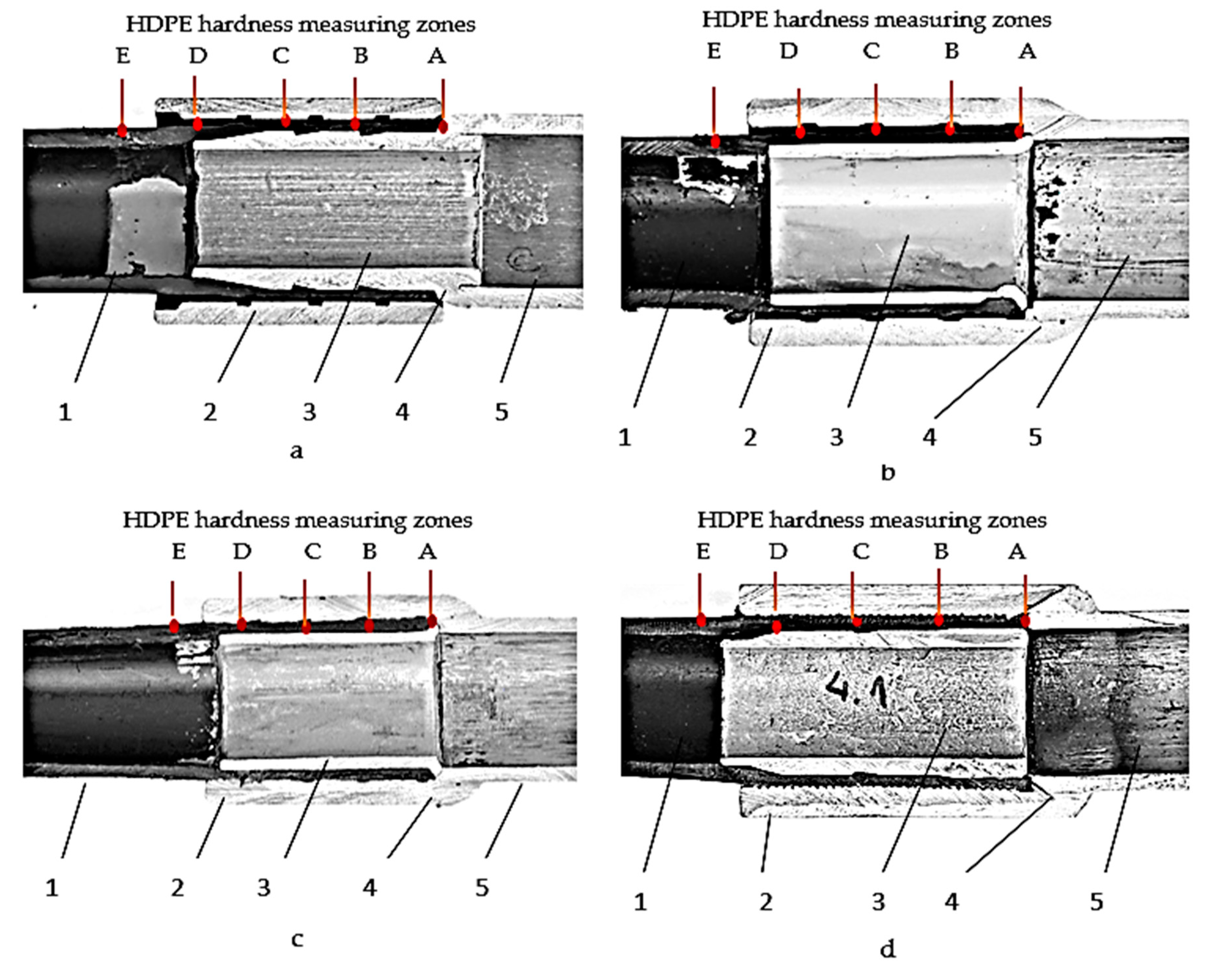
3.1. The Results of the Analysis of the Fatigue Behavior of the Transition Fittings

In order to carry out the studies from the point of view of the fatigue behavior of the fittings, nine fittings of each type were made, and these were tested by turn with the help of a fatigue testing machine. Thus, three fittings of the same type were tested for each stress condition, and the results obtained represent an average of the three measured values. After testing the four types of fittings in terms of fatigue behavior, the results shown in Table 12 were obtained. Given that on a graph in which on the ordinate (vertical axis) we have the Δ σ , and on the horizontal we have the number of cycles until breaking, the durability curves are obtained. These durability curves correspond to those specified in relations (2)–(5) and with the help of the calculation program MathCad, by the mathematical processing of the results obtained from the fatigue tests, the values p1 = 2 and r1 = 6.8 were determined for the fittings T1, for which the graph of the function Δσ1 is closest to our points represented by the vector number of cycles noted with n1 = (16210; 154610; 197750) and the force vector denoted F = (3; 2; 1). Under the same conditions, the data obtained for the fittings T2, T3 and T4 were processed and the values p2 = 1.4 and r2 = 5.2 were obtained for the fitting T2, for the fitting T3 the values p3 = 1.9 and r3 = 6.5 respectively for the fitting T4 the values p4 = 1.8 and r4 = 6.1.
Also, using equations (2 ÷ 5) Δσ was calculated, the voltage variation that appeared as a result of the variation of the force applied between a maximum and a minimum for the four types of fittings under the mentioned stress conditions, the results being presented in Table 13.
After testing the four types of fittings in terms of fatigue behavior, the results shown in Table 12 were obtained. Also, in Figure 3, a graphical evolution of the number of cycles until breaking of the samples is presented.
Also, by processing these experimental data, the durability curves were drawn in linear coordinates, Figure 4, as follows: for the T1 fitting—curve Δσ1, for the T2 fittings—Δσ2 curve, for the T3 fittings—Δσ3 curve, for the T4 fittings—Δσ4 curve.
Figure 4 shows that no durability curve is asymptotic to the horizontal axis. Therefore, these curves will intersect at some point with the horizontal axis, i.e., there is no voltage for which we have an infinite fatigue life, as Wohler’s curve is drawn theoretically, where there is a voltage σ0, for which we record infinite lifespan to fatigue. Also, the closest values observed in the case of durability curves to the real values are obtained in the case of fitting type T2, but also in the case of other types of fittings the difference is very small, falling within the range of 2–9%.
From Table 12 it is observed that, with the decrease of the test forces of the samples, the number of cycles in which the test tubes yield to the applied fatigue increases. Also, from the same table it is observed that the best behavior in response to fatigue corresponds to the type T1 fitting followed by the fittings T3, T4 and T2, respectively. The fittings of type T2, T3, T4 have the same assembly technology, but have differences in terms of the geometry of the inner and outer bush, respectively. In these conditions it can be concluded that a substantial influence on the fatigue resistance of the transition fittings has the constructive shape of the inner and outer bush, respectively.
Of the transition fittings T2, T3 and T4, the best fatigue resistance corresponds to the T3 fitting, and this demonstrates that constructive differences between the inner and outer bushes can influence the fatigue resistance. Thus, in the case of the inner bush, which has a diameter difference at one end, the fatigue resistance is influenced due to the fact that the presence of a larger diameter for the inner bush towards the end where the welded joint is to be made determines a protection of the HDPE pipe material from the heat released in the joining process by welding. Under these conditions, it is required that the inner bushings of the transition fittings present at the end where the welded joint is made, an addition of material, that would allow the amount of heat released during the welding to be absorbed.
Regarding the geometry of the outer bush, it was observed that it influences the resistance to fatigue in the sense that it is not indicated that on the surface of the bush there to be a very sharp geometric profile that causes an accentuated deformation of the material in the HDPE pipe. Thus, the profile of the channels on the surface of the outer bush must be less sharp and thus the stresses introduced in the material of the HDPE pipes should be as low as possible.
Regarding the T1 type fitting, it had the best fatigue behavior, and this can be explained both by the geometry of the inner and outer bush and by the fact that, in the assembly process of this type of fitting, the assembly process by welding is performed before inserting the HDPE pipe.
Regarding the durability curves drawn in Figure 4, it is observed that, leading a parallel line to the horizontal, the four durability curves intersect at four points that give us information on the number of cycles until yielding of the four types of fittings. It can be seen from Figure 4 that the T1 type fitting has a point characterized by the highest number of stress cycles until the fitting will fail.

3.2. The Results of the Analysis of the Hardness of the Material from the HDPE Pipes

From the analysis of the behavior under fatigue exposure of the four types of fittings, it was observed that the geometry of the inner and outer bush, respectively, can have a special influence but also the assembly technology of the applied welding. Under these conditions, at this stage of the research, a measurement was made of the value of the hardness of the material in the HDPE pipes. As for the HDPE hardness measuring points, for those four types of fittings, they are shown in Figure 1. Thus, point 1 is represented by the end of the HDPE pipe from the weld bead, and the following measuring points are arranged from 4 in 4 mm, until the HDPE pipe is no longer affected by the metal construction of the fitting. The evolution of the results obtained following the hardness measurements for the four types of fittings are presented in Figure 5.
From the analysis of the hardness values of the material from HDPE pipes, presented in Figure 5, it was observed that an additional deformation of HDPE causes an increase in hardness, but at the same time, the welding assembly technology adopted causes a change in HDPE hardness. This change in the HDPE hardness produced during the fitting assembly process is not conducive to their in use behavior.
Thus, the largest change in HDPE hardness was observed in the case of the T2 type fitting, and the smallest change in hardness was observed in the case of the T1 fitting. These differences between the hardness changes of HDPE can be explained by the fact that in the case of the T1 type fitting the welding assembly of the metal construction is done before the introduction of HDPE pipe and thus there is no influence of heat from the head affected zone (HAZ) on this. Also, the slightest change in the hardness of HDPE for fittings T2, T3, T4 was observed in the case of fitting T3 which is characterized by the fact that it has an inner bush with a special construction that prevents to some extent the penetration of heat from HAZ to HDPE. Also, an influence on the hardness changes of HDPE has the geometry of the outer bush, in the sense that, the sharper of the inner bush profile, the greater the hardness changes of HDPE.
Regarding the results obtained during the hardness measurements, they can be influenced by certain errors determined by the errors of the measuring device, but also by the positioning mode of the probe. All these possible errors do not influence the final conclusion regarding the fact that the way of deforming the material of HDPE pipes by means of external and internal bushes, but also the heat released in the process of welding joining cause a change in the hardness of the material from HDPE pipes. Under these conditions, when designing the transition fittings, special attention must be paid both to the geometry of the welded metal construction and to the adopted welding technology.

3.3. The Results of the Analysis of the Transition Fittings by the FEM

For the four types of fittings, the aim was to establish the maximum tension that appears in their material under stress conditions at a maximum force of 28,000 N. When choosing this force size, it was taken into account that in practice, the maximum load that can be applied to these types of pieces is 25,000 N, and the value considered represent this point of view.
The FEM analysis was performed for all four types of fittings and is presented in Figure 6. The results presented in Figure 6 allow us to observe the maximum tension that appears in the fitting material in case of tensile stress under the conditions mentioned above. From the results presented in Figure 6, the following values of the effective stresses in the fitting material were observed: fitting T1—10.31 MPa; T2 fitting—23.69 MPa; T3 fitting—15.71 MPa; T4 fitting—20.97 MPa.
Thus, it was concluded that the T1 type fitting has the best behavior under tensile stress and this demonstrates that both the technology of joining the fittings and the geometry of the inner and outer bush substantially influence the behavior in operation.

3.4. The Results of the Analysis of the Transition Fitting with an Improved Geometry of the Welded Construction

Following the analysis of the experimental research results, it was proposed to make a new transition fitting that has an assembly technology as close as possible to the T1 fitting technology, and, in the same type adopts the constructive elements from the structure of the other types of fittings, that have been shown to positively influence their characteristics.
Thus, for the realization of the new type of transition fitting, the inner bushing which is used to make the fittings T2 and T3, respectively, was chosen along with the outer bush used to make the type T3 fitting. The choice of these types of bushings was made considering the fact that in the experimental research it was demonstrated that the choice of these types of bushings results in an improvement of the behavior of the fittings in operation. The constructive form of the component parts of the new transition fitting (TN) is presented in Table 14, and a section through this type of transition fitting is shown in Figure 7.
This new type of transition fitting was subjected to the same tests as the four types of fittings analyzed previously. Thus, the results of the fatigue behavior analysis of this transition fitting are presented in Table 15.
The analysis of the results presented in Table 14 shows that the new type of transition fitting has a much better response to applied fatigue compared to the other four types of transition fittings analyzed previously, in the sense that an increase in the number of cycles was obtained, with approximately 50% for the TN fitting compared to the T1 fitting, which had the best fatigue behavior in relation to the T2, T3 and T4 fittings. This demonstrates that the choice of part geometry and an improved assembly technology can allow obtaining fittings with superior characteristics.
Also, the new type of transition fitting was subjected to hardness tests for HDPE material under the same conditions as T1, T2, T3 and T4 fittings. Following the hardness tests, the highest hardness 58 Sh D for HDPE was obtained, which shows that the new geometry of the inner and outer bushes, causes a very small change in the hardness of the HDPE material, which initially had a hardness of 55 Sh D. This can be explained by the fact that the influence of heat from HAZ on HDPE is very low, and the geometry adopted for the bushings does not cause a large increase in hardness.
The FEM analysis of the TN transition fitting was performed under the same conditions as in the case of the other four types of transition fittings, this being presented in Figure 8. From the results presented in Figure 8 it was observed that the TN fitting has an effective stresses in the material from component parts 6.37 MPa, which demonstrates that this type of fitting has a lower material tension by about 90% compared to the T1 fitting, which was the best of the four initially analyzed.
This much better tensile behavior of the TN fitting can be explained by the fact that the design of the transition fitting has been considerably improved by design and choosing optimal shapes for the inner bushing and the outer bushing, but also by adopting an improved welding assembly technology so that HDPE pipe is not be influenced by the heat released during the welding process.
From what is presented, it is observed that the way the welded joint is formed has a very great influence on the behavior of the fittings in use. Thus, through the design of the welded construction, HAZ must be as restricted as possible, so as not to influence the HDPE pipe. It is also necessary to consider the possibility of replacing this welding technology with an ultrasonic welding process consisting of a rotating sonotrode, which moves around the parts to be welded or that the ultrasonic welding machine that a sonotrode, around which the parts to be welded rotate. This technological solution is possible because ultrasonic welding has a multitude of advantages such as the fact that surface damage is minimal because heat is generated at the interface (very restricted HAZ) and, at the same time, is a clean joining process because it does not generate smoke or sparks during welding and is therefore considered environmentally friendly [23,24].
Also, by changing the geometry of the parts in the fitting structure, the HDPE temperature should not exceed 50 °C because above this temperature this type of material quickly loses its ductility. The process of loss of ductility depends on the morphological appearance of the HDPE structures. Furthermore, the increasing trends of the tensile modulus at the higher exposure temperature indicates temperature sensitivity on chemicrystallization [25].
The results obtained in the studies confirm those recorded in testing the tensile yield strength of HDPE using instrumented indentation tests with a flat-ended cylindrical indenter [26,27]. However, unlike previous research, different forms of inner and outer bushings were analyzed, which offer different degrees of deformation for HDPE, thus establishing the geometric shape of the welded construction that allows an optimal deformation of the HDPE pipe.
Regarding the optimal geometry of the surfaces of the inner and outer bushes, theoretical and practical research can be performed using mathematical modeling. These aspects are justified by the fact that, in many previous studies, researchers have mainly analyzed the law of mechanical deformation of flexible pipes by laboratory tests and numerical simulations [28,29].
Research has looked at the dynamic stress behavior of transition fittings because, although it was initially established that static load results in increased deformation of HDPE pipes [30], subsequent research has shown that the dynamic load was more than three times higher than the static load [31,32].
Given the conducted studies, the load at which the fittings are required can be reduced if they are covered with expanded polystyrene (EPS) to alleviate the pressure and deformation of surface-buried high density polyethylene (HDPE) flexible pipes [33]. Thus, considering the proposed solutions, regarding the improvement of the welded construction of the transition fittings, but also the technical solutions proposed by other researchers, conditions are created so that the lifespan and the number of stress cycles until their rupture increase substantially.

4. Conclusions

Transition fittings from steel pipes to HDPE pipes that ensure the connection of pipes used to transport natural gas are a very important product that must be safe in use. The big problem that appears in obtaining the fittings is related to the fact that it is necessary to form an assembly between two pipes made of materials with completely different properties. Also, the research was guided by the following aspects: the geometry of the surfaces of the parts in the structure of a transition fitting is very complex; it is necessary to make a welded metal construction that is assembled with HDPE pipe. The researches initially considered four transition fitting variants which were analyzed from the point of view of their fatigue stress behavior and from the point of view of their tensile stress. It was also analyzed how the HDPE hardness evolved in the deformation zone. Thus, the research demonstrated the following:
  • the fatigue resistance of the fittings can be considerably improved in the conditions in which an optimal geometry is chosen for the inner and outer bush, respectively;
  • the fatigue load behavior is very different for the four types of fittings, large differences being noted in the number of cycles it withstands. Thus, in the case of stress fittings with a force F = ±1 kN, a number of stress cycles of minimum nmin = 137,570 and maximum nmax = 197,750 was recorded, thus substantial differences of approximately 45% are observed and in the case of the case a force F = ±3 kN is applied to the fittings, the differences are even greater, about 60%;
  • the adoption of a new constructive variant allowed an improvement of the behavior under fatigue, so that the number of stress cycles for a force F = ±1 kN increased from n = 197,750 for the T1 fitting to n = 296,650 for the TN fitting;
  • the transition fittings behave better at the traction request in the conditions in which the welded construction has an optimal geometry and the best parameters for the welding regime are adopted;
  • HDPE undergoes hardness changes in the deformation zone, and in order for the changes to be as small as possible, an optimization of the geometry of the inner and outer bush is required, but also taking measures to transfer some of the heat from the HAZ to the HDPE pipe;
  • the hardness changes of HDPE were the largest in the case of the T2 fitting, where they were approximately 10oSh D. These changes can be explained mainly by the fact that on the inner surface of the outer sleeve a series of square-shaped channels are present, which produce a large HDPE deformation;
  • the adoption of a new geometric shape for the welded construction allowed us to obtain a new TN transition fitting, characterized by an improvement of the fatigue stress resistance by approximately 50%, a decrease in material stress at the tensile stress by approximately 90% and a reduction of HDPE hardness change.
All these results prove that the new TN transition fitting is a much more reliable product and has a better operating behavior. Also, the results obtained in the research can represent technical solutions for assembling other types of products that have in their structure metal parts or HDPE parts. Future research will consider identifying the welding process that will allow one to obtain welded assemblies with the best characteristics.

Author Contributions

Conceptualization, D.D. and I.R.; methodology, D.D.; software, D.D.; validation, D.D., I.R. and I.B.; formal analysis, I.R.; investigation, D.D.; resources, I.R.; data curation, I.B.; writing—original draft preparation, I.B and I.R.; writing—review and editing, D.D.; visualization, I.B and I.R..; supervision, D.D.; project administration, I.R.; funding acquisition, I.R. All authors have read and agreed to the published version of the manuscript.

Funding

Project financed by Lucian Blaga University of Sibiu & Hasso Plattner Foundation research grants LBUS-IRG-2020-06.

Conflicts of Interest

The authors declare no conflict of interest

References

  1. Abdollahi, A.; Ahnaf Huda, A.S.; Kabir, A.S. Microstructural characterization and mechanical properties of fiber laser welded CP-Ti and Ti-6Al-4V similar and dissimilar joints. Metals 2020, 10, 747. [Google Scholar] [CrossRef]
  2. Lambiase, F.; Genna, S.; Kant, R. A procedure for calibration and validation of FE modelling of laser-assisted metal to polymer direct joining. Opt. Laser Technol. 2018, 98, 363–372. [Google Scholar] [CrossRef]
  3. Kawahito, Y.; Niwa, Y.; Katayama, S. Laser direct joining between stainless steel and polyethylene terephthalate plastic and reliability evaluation of joints. Weld. Int. 2014, 28, 107–113. [Google Scholar] [CrossRef]
  4. Katayama, S. Laser welding. J. Jpn. Weld. Soc. 2008, 78, 40–54. [Google Scholar]
  5. Beyer, E.; Brenner, B.; Klotzbach, A.; Nowotny, S. Laser macro processing—Today and tomorrow. Online Proceed. Lamp 2006, 2006. JLPS, Kyoto. [Google Scholar]
  6. Nakamura, H.; Terada, M.; Hirata, M.; Sakai, T. Application to the plastic parts welding of diode laser. 59th Laser Mater. Process. Conf. 2003, 2003, 1–7. [Google Scholar]
  7. Kurauchi, T.; Senzaki, Y. Technology of laser welding. Toyoda Gosei Tech. Rev. 2003, 45, 31–32. [Google Scholar]
  8. Katayama, S.; Kawahito, Y.; Niwa, Y.; Tange, A.; Kubota, S. Laser direct joining between stainless steel and amorphous polyamide plastic. Q. J. Jpn. Weld. Soc. 2007, 25, 316–322. [Google Scholar] [CrossRef] [Green Version]
  9. Huaizhong, Z.; Xizhang, C.; Jie, H. Weld ability of dissimilar material of 304 stainless steel and polyethylene terephthalate. J. Chin. Adv. Mater. Soc. 2017, 5, 204–214. [Google Scholar] [CrossRef]
  10. Al-Lami, P.; Sinapius, M. Eco-efficiency assessment of manufacturing carbon fiber reinforced polymers (CFRP) in aerospace industry. Aerosp. Sci. Technol. 2018, 79, 669–678. [Google Scholar] [CrossRef]
  11. Kashaev, N.; Ventzke, V.; Riekehr, S.; Dorn, F.; Horstmann, M. Assessment of alternative joining techniques for Ti–6Al–4V/CFRP hybrid joints regarding tensile and fatigue strength. Mater. Des. 2015, 81, 73–81. [Google Scholar] [CrossRef] [Green Version]
  12. Joesbury, A.M.; Colegrove, P.A.; Van Rymenant, P.; Ayre, D.S.; Ganguly, S.; Williams, S. Weld-bonded stainless steel to carbon fibre-reinforced plastic joints. Mater. Process. Technol. 2018, 251, 241–250. [Google Scholar] [CrossRef]
  13. Xu, M.; Liu, B.; Zhao, Y.; Wang, Z.; Dong, Z. Direct joining of thermoplastic ABS to aluminium alloy 6061–T6 using friction lap welding. Sci. Technol. Weld. Join. 2020, 25, 391–397. [Google Scholar] [CrossRef]
  14. Huang, Y.; Meng, X.; Xie, Y.; Li, J.; Wan, L. Joining of carbon fiber reinforced thermoplastic and metal via friction stir welding with co-controlling shape and performance. Compos. A Appl. Sci. Manuf. 2018, 112, 328–336. [Google Scholar] [CrossRef]
  15. Amza, G.; Dobrotǎ, D. Ultrasound effect on the mechanical properties of parts loaded by welding. Metalurgija 2013, 52, 83–86. [Google Scholar]
  16. Arkhurst, B.M.; Seol, J.B.; Lee, Y.S.; Lee, M.; Kim, J.H. Interfacial structure and bonding mechanism of AZ31/carbon-fiber-reinforced plastic composites fabricated by thermal laser joining. Compos. B Eng. 2019, 167, 71–82. [Google Scholar] [CrossRef]
  17. Gao, Y.Y.; Liu, H.X.; Li, P. Study of laser transmission laser joining characteristics for Ti coated alumina ceramic and PET. Chin. J. Lasers 2013, 40, 56–62. [Google Scholar]
  18. Jung, K.W.; Kawahito, Y.; Takahashi, M.; Katayama, S. Laser direct joining of carbon fiber reinforced plastic to aluminum alloy. J. Laser Appl. 2013, 25, 530–533. [Google Scholar] [CrossRef]
  19. Lambiase, F.; Genna, S.; Kant, R. Optimization of laser-assisted joining through an integrated experimental-simulation approach. Int. J. Adv. Manuf. Technol. 2018, 97, 2655–2666. [Google Scholar] [CrossRef]
  20. Vesenjak, M.; Nishi, M.; Nishi, T.; Marumo, Y.; Krstulović-Opara, L.; Ren, Z.; Hokamoto, K. Fabrication and mechanical properties of rolled aluminium unidirectional cellular structure. Metals 2020, 10, 770. [Google Scholar] [CrossRef]
  21. Dimitrescu, A.; Niţoi, D.F.; Dobrotă, D.; Apostolescu, Z. Researches and studies regarding brazed aluminium alloys microstructure used in aeronautic industry. Metalurgija 2015, 54, 383–386. [Google Scholar]
  22. Schrek, A.; Brusilová, A.; Švec, P.; Gábrišová, Z.; Moravec, J. Analysis of the drawing process of small-sized seam tubes. Metals 2020, 10, 709. [Google Scholar] [CrossRef]
  23. Li, J.; Zhang, K.; Li, Y.; Liu, P.; Xia, J. Influence of interference-fit size on bearing fatigue response of single-lap carbon fiber reinforced polymer/Ti alloy bolted joints. Tribol. Int. 2016, 93, 151–162. [Google Scholar] [CrossRef]
  24. Bhudolia, S.K.; Gohel, G.; Leong, K.F.; Islam, A. Advances in ultrasonic welding of thermoplastic composites: A review. Materials 2020, 13, 1284. [Google Scholar] [CrossRef] [PubMed] [Green Version]
  25. Hsueh, H.-C.; Kim, J.H.; Sara Orski, F.A.; Jacobs, D.; Perry, L.; Hunston, D.; White, C.; Sung, L. Micro and macroscopic mechanical behaviors of high-density polyethylene under UV irradiation and temperature. Polym. Degrad. Stab. 2020, 174, 109098. [Google Scholar] [CrossRef]
  26. American Society for Testing and Materials. ASTM D638–14, Standard Test. Method for Tensile Properties of Plastics; ASTM International: West Conshohocken, PA, USA, 2015. [Google Scholar]
  27. Won, J.; Kim, S.; Kwon, O.; Kim, Y.; Kwon, D. Evaluation of tensile yield strength of high-density polyethylene in flat-ended cylindrical indentation: An analytic approach based on the expanding cavity model. J. Mater. Res. 2020, 35, 206–214. [Google Scholar] [CrossRef]
  28. Arockiasamy, M.; Chaallal, O.; Limpeteeprakarn, T. Full-scale field tests on flexible pipes under live load application. J. Perform. Constr. Fac. 2006, 20, 21–27. [Google Scholar] [CrossRef]
  29. Zhou, M. Mechanical Response of Buried HDPE Pipes Subjected to the Ground Subsidence. Ph.D. Thesis, Southeast University, Nanjing, China, July 2018. [Google Scholar]
  30. Peindl, R.D.; Janardhanam, R.; Burns, F. Evaluation of flowable fly-ash backfill. I: Static loading. J. Geotech. Eng. 1992, 118, 449–463. [Google Scholar] [CrossRef]
  31. Hyodo, M.; Yasuhara, K. Analytical procedure for evaluating pore-water pressure and deformation of saturated clay ground subjected to traffic loads. In Numerical Methods in Geomechanics Volume 1, Proceedings of the 6th International Conference on Numerical Methods in Geomechanics, Innsbruck, Austria, 11–15 April 1988; Swoboda, G., Ed.; Routledge: Abingdon, UK, 2017; pp. 653–658. [Google Scholar]
  32. Fang, H.; Tan, P.; Du, X.; Li, B.; Yang, K.; Zhang, Y. Numerical and experimental investigation of the effect of traffic load on the mechanical characteristics of HDPE Double-Wall corrugated pipe. Appl. Sci. 2020, 10, 627. [Google Scholar] [CrossRef] [Green Version]
  33. Tafreshi Moghaddas, S.N.; Joz Darabi, N.; Dawson, A.R. Combining EPS geofoam with geocell to reduce buried pipe loads and trench surface rutting. Geotext. Geomembr. 2020, 48, 400–418. [Google Scholar] [CrossRef]
Figure 1. Types of transition fittings obtained: (a)—T1 transition fittings; (b)—T2 transition fitting; (c)—T3 transition fitting; (d)—T4 transition fitting; 1—HDPE pipe; 2—outer bush; 3—inner bush; 4—welding bead; 5—steel pipe.
Metals 10 01231 g001
Figure 2. The loading mode and the restrictions applied to the transition fittings subjected to analysis by the finite element method.
Metals 10 01231 g002
Figure 3. Graphical representation of the number of cycles until give in through fatigue.
Metals 10 01231 g003
Figure 4. Durability curves of fittings in linear coordinates.
Metals 10 01231 g004
Figure 5. The hardness values, Shore D, for the four types of fittings.
Metals 10 01231 g005
Figure 6. FEM analysis for the four types of transition fittings: (a): T1 fitting; (b): T2 fitting; (c): T3 fitting; (d): T4 fitting.
Metals 10 01231 g006aMetals 10 01231 g006b
Figure 7. Section through TN transition fitting: 1—HDPE pipe; 2—outer bush; 3—inner bush; 4—welding bead; 5—steel pipe.
Metals 10 01231 g007
Figure 8. FEM analysis for TN fitting.
Metals 10 01231 g008
Table 1. Chemical composition for steel P 235 TR 1.
ElementCMnSiSPAlVTiCrMoNiFe
wt%max 0.16max 1.2max 0.35max 0.020max 0.025max 0.020max 0.02max 0.04max 0.30max 0.08max 0.30balanced
Table 2. Mechanical properties for steel P 235 TR.
Yield Strength Rp0.2 (MPa)Tensile Strength Rm (MPa)Elongation A5 (%)Minimum Value of Notch Impact Energy (J) -Notch Impact Test-Longitudinal
minmin25−20 °C0 °C+20 °C
23542017395158
Table 3. Chemical composition for the filler material with E 50 4 B 4 2 H5.
ElementCMnSiFe
wt%max. 0.08max. 1.7max. 0.7balanced
Table 4. Mechanical properties for the filler material with E 50 4 B 4 2 H5.
Yield Strength
Rp0.2 (MPa)
Tensile Strength
Rm (MPa)
Elongation
A5 (%)
Impact Values
ISO-V KV (J)
Min 580560–720Min 26−40 °C+20 °C
90170
Table 5. The main physical-mechanical properties of HDPE.
CharacteristicValueUnit of MeasurementTest Standard
HDPE 80HDPE 100
Density0.930.95g/cm3EN ISO 1183-1
Breaking strength at 23 °C1830N/mm2EN ISO 527-1
Modulus of elasticity, at 23 °C 700900N/mm2EN ISO 527-1
The Charpy impact resistant, at 23 °C11083kJ/m2EN ISO 179-1
The Charpy impact resistant, at −40 °C713kJ/m2EN ISO 179-1
Ball imprint hardness, at (132 N)37N/mm2EN ISO 2030-1
Crystallite melting point131130°CDIN 51007
Thermal conductivity, at 23 °C0.430.38W/mKEN 12664
Coefficient of linear expansion0.15-0.20Mm/mKDIN 53752
Water absorption, at 23 °C0.01-0.04%EN ISO 62
The Index of Oxygen Limit (LOI)17.4%ISO 4589-1
Table 6. Welding regime of the samples.
Voltage
U
Amperage
A
Welding Speed
vs. (mm/s)
Heat input
El (J/mm)
201003.1645
Table 7. The constructive shape of the steel pipe.
Transition Fitting TypeSteel Pipe
T1, T2, T3 Metals 10 01231 i001
T4 Metals 10 01231 i002
Table 8. Constructive shape of HDPE pipe.
Transition Fitting TypeHDPE Pipe
T1, T2, T3, T4 Metals 10 01231 i003
Table 9. The constructive shape of the inner bush.
Transition Fitting TypeInner Bush
T1 Metals 10 01231 i004
T2, T3 Metals 10 01231 i005
T4 Metals 10 01231 i006
Table 10. Constructive shape of the outer bushes.
Transition Fitting TypeOuter Bush
T1 Metals 10 01231 i007
T2 Metals 10 01231 i008
T3 Metals 10 01231 i009
T4 Metals 10 01231 i010
Table 11. Applied forces for fatigue tests.
Samples±Force (kN)Frequency (Hz)
T1, T2, T3, T4±110
T1, T2, T3, T4±210
T1, T2, T3, T4±310
Table 12. Results obtained after fatigue testing of the samples.
Samples±Force (kN)Frequency (Hz)Time (s)Number of Cycles n
T1±310161216,210
±21015,461154,610
±110197,751197,750
T2±310117111,710
±21010,551105,510
±11013,757137,570
T3±310163116,310
±21013,281132,810
±11018,367183,670
T4±310126212,620
±21011,797117,970
±11015,789157,890
Table 13. Voltage variation values Δ σ .
Fitting TypeForce (kN) Δ σ
T1±316.06
±26.38
±15.64
T2±36.85
±21.33
±11.11
T3±315.47
±25.20
±14.39
T4±312.27
±23.51
±12.98
Table 14. Transition fitting structure TN.
The Piece of the Structure of the Proposed Transition FittingThe Shape of the Piece in the Structure of the Transition Fitting TN
Steel pipe Metals 10 01231 i011
Pipe HDPE Metals 10 01231 i012
Inner bush Metals 10 01231 i013
Outer bush Metals 10 01231 i014
Table 15. Results obtained after fatigue testing of the TN fitting.
Sample±Force (kN)Frequency (Hz)Time (s)Number of Cycles n
TN±310263126,310
±21021,981219,810
±11029,665296,650

