Article

In Situ Synchrotron X-ray Diffraction Investigations of the Nonlinear Deformation Behavior of a Low Modulus β-Type Ti36Nb5Zr Alloy

1
School of Materials Science and Physics, China University of Mining and Technology, Xuzhou 221116, China
2
School of Materials Science and Engineering, Jiangsu University, Zhenjiang 212013, China
3
School of Materials Science and Engineering, Beihang University, Beijing 100191, China
*
Authors to whom correspondence should be addressed.
Metals 2020, 10(12), 1619; https://doi.org/10.3390/met10121619
Submission received: 4 November 2020 / Revised: 24 November 2020 / Accepted: 30 November 2020 / Published: 2 December 2020
(This article belongs to the Special Issue Titanium and Its Alloys for Biomedical Applications)

Abstract

:
The low modulus β-type Ti alloys usually have peculiar deformation behaviors due to their low phase stability. However, the study of the underlying mechanisms is challenging since some physical mechanisms are fully reversible after the release of the load. In this paper, the deformation behavior of a low modulus β-type Ti36Nb5Zr alloy was investigated with the aid of in situ synchrotron X-ray diffraction (SXRD) during tensile loading. The evolution of lattice strains and relative integrated diffraction peak intensities of both the β and α” phases were analyzed to determine the characteristics of the potential deformation mechanisms. Upon loading, the α” diffraction spots appeared at specific azimuth angles of the two-dimensional SXRD patterns due to the <110> fiber texture of original β grains and the selection of favorable martensitic variants. The nonlinear deformation behavior originated from a reversible stress-induced martensitic transformation (SIMT). However, the SIMT contributed a little to the large recoverable strain of over 2.0%, which was dominated by the elastic deformation of the β phase. Various deformation mechanisms were activated successively at different applied strains, including elastic deformation, SIMT and plastic deformation. Our investigations provide in-depth understandings of the deformation mechanisms in β-type Ti alloys with low elastic modulus.

Graphical Abstract

1. Introduction

Titanium (Ti) and its alloys been used extensively for biomedical applications due to their excellent combined properties of low elastic modulus, high specific strength, excellent corrosion resistance, complete inertness to body environment and superior biocompatibility [1,2]. Among the mechanical properties essential for implant materials, elastic modulus, whose value should be as close as possible to that of human bone, is of considerable importance [3]. Although the elastic modulus of the widely used pure Ti and Ti-6Al-4V is lower (104 GPa and 110 GPa, respectively) than that of other conventional metallic biomaterials such as 316 L stainless steel and cobalt–chromium alloys (higher than 200 GPa), it is still much higher than that of natural human bone (10–30 GPa) [4]. The modulus mismatch between implants and surrounding human bones can lead to a stress shielding effect, resulting in bone resorption and premature failure of the implant [5]. Additionally, the release of toxic Al and V ions from Ti-6Al-4V is associated with long-term health problems, such as Alzheimer disease, neuropathy and ostemomalacia [6]. Consequently, this has led to the development of β-type Ti alloys that consist of non-toxic alloying elements and process lower modulus than that of α- and (α + β)-type Ti alloys [7,8,9].
The β-type Ti alloys can exhibit a martensitic transformation from the body centered cubic (bcc) β phase (space group, Im-3m) to the orthorhombic α” phase (space group, Cmcm) [10,11]. The martensitic transformation temperature decreases with the increase in the concentration of alloying elements, and the single β phase can be kept to room temperature upon quenching when the concentration exceeds a critical value [12,13]. It has been well recognized that the elastic modulus of β phase in Ti alloys is closely related their phase stability, with lower modulus corresponding to lower phase stability [14]. Therefore, the concentration of β stabilizers in most low modulus β-type Ti alloys was carefully designed to be as low as possible while being slightly higher than the critical concentration, in order to stabilize the single β phase against α” martensitic transformation [15]. These alloys with low phase stability (i.e., low modulus) also have various deformation mechanisms, e.g., stress-induced martensitic transformation (SIMT), deformation twinning, dislocation slip, etc. [16,17,18,19]. The various deformation mechanisms enable the alloys to possess unique mechanical properties involving shape memory effect [20], superelasticity [21], high strain hardening rate [22], large recoverable strain [23], and nonlinear elastic-like behavior [24]. Among these properties, nonlinear elasticity has attracted considerable attention, since it exists in several multifunctional Ti alloys including the Gum Metal and Ti24Nb4Zr8Sn alloy [25,26]. Although several reversible deformation mechanisms such as lattice distortion [27], nanodisturbance [28], dislocation loops [29], and strain glass transition [30], were proposed, it was generally accepted that SIMT plays an important role in this kind of peculiar deformation behavior [31,32].
Due to the reversibility of SIMT after the release of the stress, in-situ experiments provide a very efficient method to explore the deformation mechanism of metastable β-type Ti alloys. Currently, in-situ conventional X-ray diffraction (XRD) has been employed to detect stress-induced α” martensite in Ti13Nb4Mo and Ti26Nb alloys [33,34]. However, the volume fraction of stress-induced α” martensite is usually very low in Ti alloys with nonlinear elasticity, which makes it difficult or even impossible to characterize the SIMT through conventional XRD. Furthermore, it is difficult to separate the main peaks of the β phase and α” martensite, as the laboratory X-ray sources have relatively great wavelength and the Ka1 and Ka2 wavelengths coexist. Especially, the identification of β phase and α” martensite from conventional XRD patterns will become even harder for alloys subjected to severe cold deformation because of the broadening of diffraction peaks. By contrast, synchrotron X-ray diffraction (SXRD) technique can trace the formation of a small volume fraction of phases during deformation due to the combination of short wavelength, good monochromaticity, high penetration, low absorption, and high resolution [35,36,37]. In-situ SXRD have been used to study the nonlinear deformation behavior of the Ti24Nb0.5O (at.%), Ti24Nb4Zr8Sn and Gum Metal, and it is demonstrated that SIMT, to a small extent, really exists during loading and contributes to the nonlinear elasticity [38,39,40].
Recently, our group developed several TiNb-based alloys with the β stabilizer concentration below the critical value [41,42]. These alloys consist of β and α” phases in solution treated and quenched states, suggesting the intrinsic low β phase stability. Upon cold rolling plus subsequent short time annealing treatment, single β phase was nearly obtained due to the suppression of martensitic transformation. Furthermore, the precipitates formed during annealing treatment did not result in a detectible increase in β stabilizers in residual β matrix, and thus the β stabilizer concentration of β matrix after thermo-mechanical treatment is identical to that in solution treated state [43]. As a result, even lower elastic modulus was realized in these alloys, e.g., 46 GPa for the Ti36Nb5Zr alloy and 36 GPa for the Ti33Nb4Sn alloys [41,43]. Interestingly, the Ti36Nb5Zr alloy subjected to cold rolling plus annealing treatment exhibits a nonlinear deformation behavior [44], similar to that of Ti24Nb4Zr8Sn and Gum metal. Since the Ti36Nb5Zr alloys have lower β phase stability than the low modulus Ti alloys with chemical composition above the critical concentration, SIMT might occur during loading and contribute to its deformation behavior. However, α” martensite has not been observed by conventional XRD and the underlying mechanism for the peculiar deformation behavior remains ambiguous.
In this paper, in situ SXRD experiments during uniaxial tensile loading were performed to explore the deformation mechanisms in the Ti36Nb5Zr alloy. The one-dimensional (1D) and two-dimensional (2D) SXRD patterns were obtained from in situ measurements to characterize the microstructural evolution of the alloy during in situ loading. Special attention was focused on the evolution of lattice strains and relative integrated diffraction peak intensities of both the β and α” phases as functions of macroscopic applied strain. Our results indicated that the peculiar deformation behavior was closely related to various kinds of deformation mechanisms including elastic deformation, SIMT and plastic deformation, which were activated at different external strains.

2. Materials and Methods

An ingot with a nominal composition of Ti36Nb5Zr (wt.%) was fabricated by arc melting in an argon atmosphere using high purity Ti (99.99%), Nb (99.95%) and Zr (99.95%). The ingot was re-melted four times in the furnace to obtain chemical composition homogeneity. The as-cast ingot was hot forged to a billet with a thickness of 8 mm and width of 60 mm, and then homogenized at 1223 K for 5 h in vacuum, followed by water quenching. The homogenized billet was cold rolled into a plate of approximately 1 mm in thickness with a final reduction ratio of 87.5%. The tensile specimens with the rolling direction parallel to the loading axis were cut from the cold rolled plate using an electro-discharge machine. These tensile specimens were annealed at 698 K for 20 min and finally quenched into water. Uniaxial tensile tests were conducted at a strain rate of 1 × 10⁴ s−1 on an Instron 5982 machine using specimens with a gage length of 30 mm and a cross section of 1 × 1.46 mm2. In order to ensure accuracy of strain, a strain extensometer was used to record the stress–strain curves.
In situ SXRD experiments were conducted during tensile loading on the 11-ID-C beamline at the Advanced Photon Source, Argonne National Laboratory. High-energy X-rays with an energy of 115 keV, wavelength of 0.10798 Å and beam size of 0.4 × 0.4 mm2 were used in transmission geometry, as shown in the schematic set-up in Figure 1. A PerkinElmer large area detector (PerkinElmer Inc., Waltham, MA, USA) of 2048 × 2048 pixels with a spatial resolution of 200 μm (pixel size) was placed behind the sample to collect the 2D diffraction patterns. The loading direction (LD) and the beamline are parallel to the rolling direction (RD) and the normal direction (ND) of the rolled plate, respectively. The azimuth angles (φ: 0–360°) at the Debye rings are defined to be 0° and 90° at the transverse direction (TD) and the longitudinal direction (parallel to LD), respectively. Fit2d software was employed to process the 2D diffraction images, and standard CeO2 powder was used for calibration. The 1D SXRD spectrums were obtained by integrating along specific azimuth angles over a range of ±10° in the 2D diffraction patterns. The positions and areas of 1D diffraction peaks were determined by Gaussian fit. The evolution of the interplanar spacing (d-spacing) with respect to the initial state is indicated by the lattice strain, i.e., εhkl = (dhkl d hkl 0 )/ d hkl 0 , where dhkl is the interplanar spacing of the (hkl) crystal plane with an external stress. The d hkl 0 is determined from the d-spacing of stress-free sample for the β phase, and from the d-spacing of sample subject to the stress that is high enough to resolve the accurate position of the martensite peak for the α” phase. The relative intensity is defined as the ratio of the integrated area of a peak to that at the strain-free state for the β phase and to that at the maximum applied strain for the α” phase, respectively.

3. Results

3.1. Microstructure and Macroscopic Mechanical Behavior

The microstructural evolution of Ti36Nb5Zr alloy during thermo-mechanical treatment has been described in detail in our previous work [41,44]. In brief, the Ti36Nb5Zr alloy after cold rolling and short time annealing treatment consists of a dominant β phase and a trace of a nanosized α phase. The annealing treatment did not result in significant recrystallization due to the low annealing temperature and short duration. The existence of high density of dislocations and grain boundaries suppressed the formation of α” martensite in thermo-mechanically treated alloys, although the solution treated alloy consisted of dual (β + α”) phases. Figure 2a,b present the 2D SXRD pattern and 1D SXRD spectrum obtained by integrating over the entire 360° of the Ti36Nb5Zr alloy before tensile testing. It can be seen that the intensity of peaks for the α phase is very weak in comparison to that for the β phase, verifying that the volume fraction of α phase is very low and thus its precipitation should not result in obvious chemical stabilization of the residual β matrix.
The uneven intensity distribution of the 2D SXRD pattern along different azimuth angles indicates that the alloy has a clear preferential orientation. The intensity distributions of the {110}β and {200}β diffraction peaks were plotted against the azimuth angle, as shown in Figure 2c. The maximum of the diffraction intensity for the {110}β peak appears at φ values of 0°, 90°, 180° and 360°, suggesting the existence of α-fiber texture components (i.e., grains with <110>β crystal direction parallel to RD). The azimuth angle of maximum diffraction intensity between the {110}β and {200}β peaks can be determined to be 46° ± 2°. Combined with the fact that the angle between the {110}β and {200}β crystal planes for bcc structure is 45°, it can be demonstrated that the texture component of the cold rolled and annealed Ti36Nb5Zr alloy is {001}<110> [36]. This kind of texture is commonly observed in β-type TiNb-based alloys subjected to cold rolling/annealing or warm rolling/annealing treatment, and is closely related to the martensitic transformation behavior [38,45].
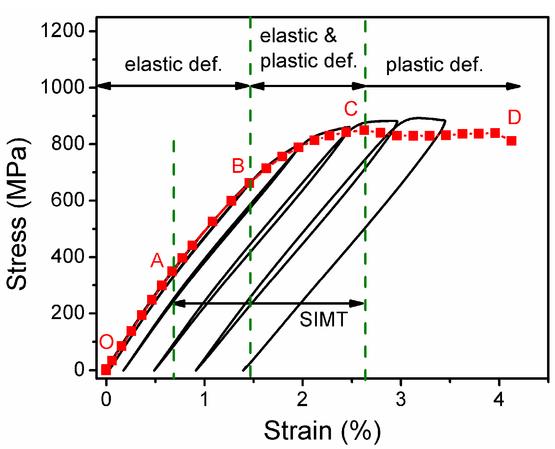
Figure 3a shows the cyclic tensile stress–strain curves at an interval of 0.5% to a total strain of 3.5%. The loading and unloading curves to a strain of 1% are overlapped, and the 1.5% loading strain is almost fully recovered during unloading with a residual strain of only 0.03%. The recoverable strain increases with increasing applied external strain, e.g., 2.01% and 2.11% are achieved at a loading strain of 2.5% and 3.5%, respectively. It is worth noting that a nonlinear deformation behavior is clearly observed when the loading strain exceeds the linear elastic range limit of ~0.6%. The peculiar nonlinear deformation behavior as well as large recoverable strain might be attributed to the low β phase stability of the Ti36Nb5Zr alloy, since such a phenomenon is usually observed in metastable β-type Ti alloys [25,46]. Figure 3b present the tensile stress–strain curve during in situ SXRD experiment, and 2D diffraction patterns were taken at each block on the curve. The nonlinearity of the stress–strain curve upon in situ tensile loading is similar to that upon cyclic loading in Figure 3a. Furthermore, the in situ stress–strain curve can be divided into several stages by points O to D. OA (<0.67% strain) is undoubtedly the initial linear elastic deformation, while the mechanism of other stages will be discussed later. It is worth noting that no strain extensometer was used during the in-situ experiment, leading to overestimation of strains in Figure 3b. Therefore, the linear elastic range limit (~0.67%) in Figure 3b is slightly higher than that in Figure 3a (~0.6%).
The 2D SXRD patterns of points D (corresponding to the maximum of external strain of 4.13%) and E (corresponding to the sample after fracture, i.e., the release of external strain) are shown in Figure 3c,d. Diffraction spots ascribed to the (021) crystal plane of α” martensite can be clearly observed in diffraction rings at an applied strain of 4.13%, demonstrating the existence of SIMT. Moreover, the angle between the (021)α diffraction spots and the loading direction is about 24°, and this will be explained by the preferred selection of martensitic variants during SIMT in the next section. Therefore, the specific direction (SD) with an azimuth angle of 66° (i.e., 24° from loading direction) as well as the loading direction (LD, azimuth angle: 90°) will be selected to clarify the microscopic mechanisms of deformation for the present Ti36Nb5Zr alloy. After the release of applied strain, the α” martensite disappeared and the 2D SXRD pattern was almost same with that before the tensile test (Figure 2a), indicating the complete reversibility of SIMT.

3.2. In Situ SXRD Characterization along the LD and SD

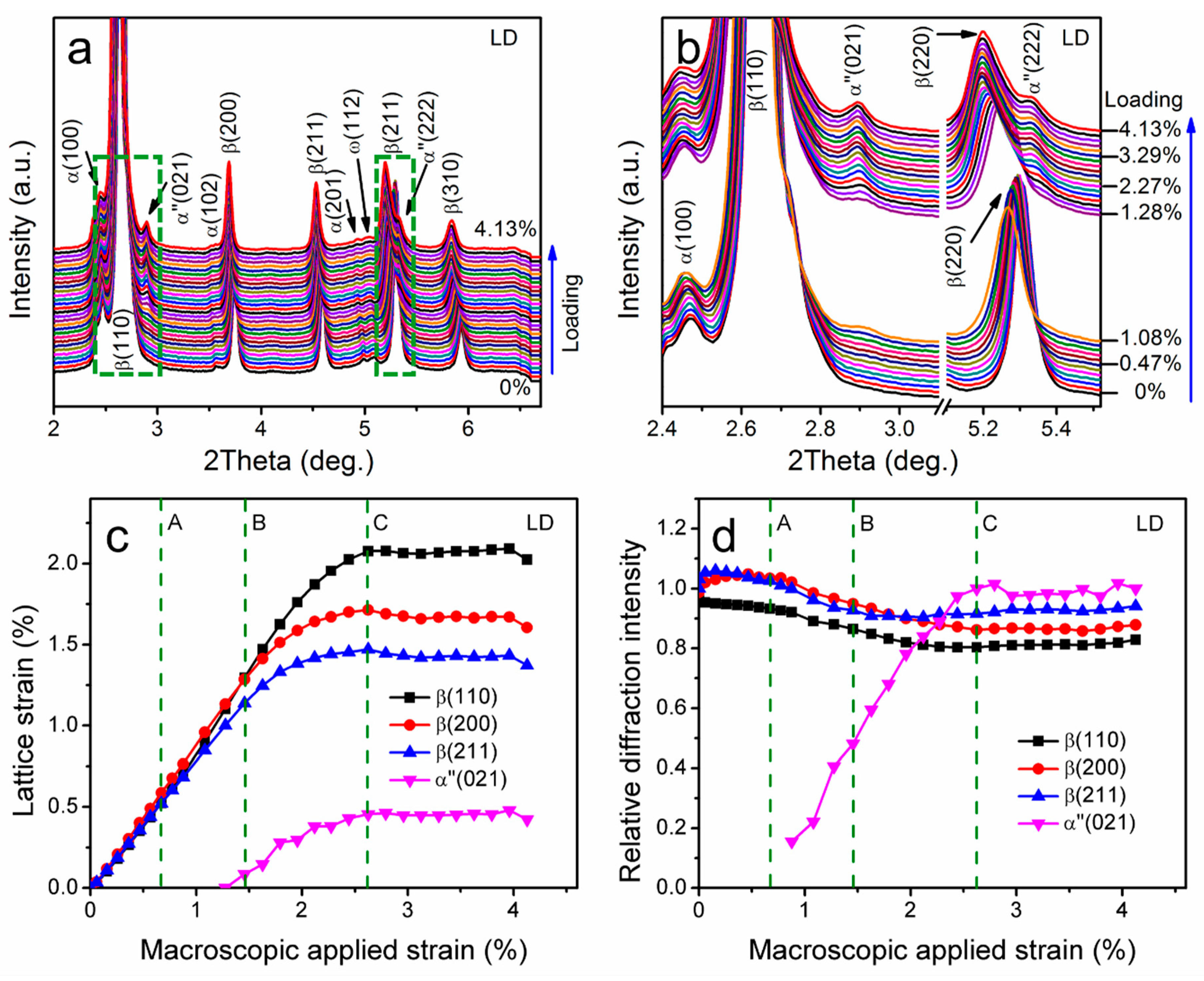
Figure 4a,b show the 1D SXRD spectrums during in situ tensile loading obtained by integrating along the longitudinal direction (φ: 80–100°) of the 2D SXRD patterns. Upon loading, the diffraction peaks of the β phase shift slightly towards lower Bragg angles, demonstrating a tensile elastic deformation in the LD. The (021)α and (222)α diffraction peaks are present at an applied strain of 0.88% and 1.28%, respectively. With the increase in external strain, the diffraction peaks of α” martensite intensified, indicating a progressive transformation.
Figure 4c,d show the evolution of the lattice strains and relative integrated diffraction peak intensities in the LD for the (110)β, (200)β, (211)β and (021)α peaks during in situ tensile loading. The d 021 0 of α” martensite is defined to be the d-spacing at an applied strain of 1.28%, since the (021)α peaks at lower external strains are too weak to be fitted for accurate peak positions and it is also difficult to obtain the d-spacing of martensite under zero external stress due to the complete reversibility of SIMT in the present alloy. In the stage of O–A–B (applied strain range: 0–1.46%), the lattice strains of all β crystal planes increase linearly with the increase in external strain, implying a elastic deformation behavior; in the stage of B–C (applied strain range: 1.46–2.62%), the lattice strains of the β crystal planes continue to increase at a much reduced rate with further increase in the applied strain, indicating the commencement of plastic deformation; in the stage of C–D (applied strain range: 2.62–4.13%), the lattice strains of both the β and α” crystal planes remain almost constant, suggesting a complete stop of elastic deformation in the local area under SXRD study. The relative diffraction intensity reveals that progressive SIMT occurred with an external strain of up to 2.62% (point C), which can be demonstrated by the continuous increase in relative intensity of (021)α at the expense of that of (110)β, (200)β and (211)β. It is worth noting that the nonlinear deformation behavior appears at a strain of 0.67% (point A) while the SIMT along LD is first observed at a strain of 0.88%. The martensitic variants characterized by the (021)α peak along the LD might not form firstly during tensile loading; the examination of martensitic transformation along other azimuth angles should be considered.
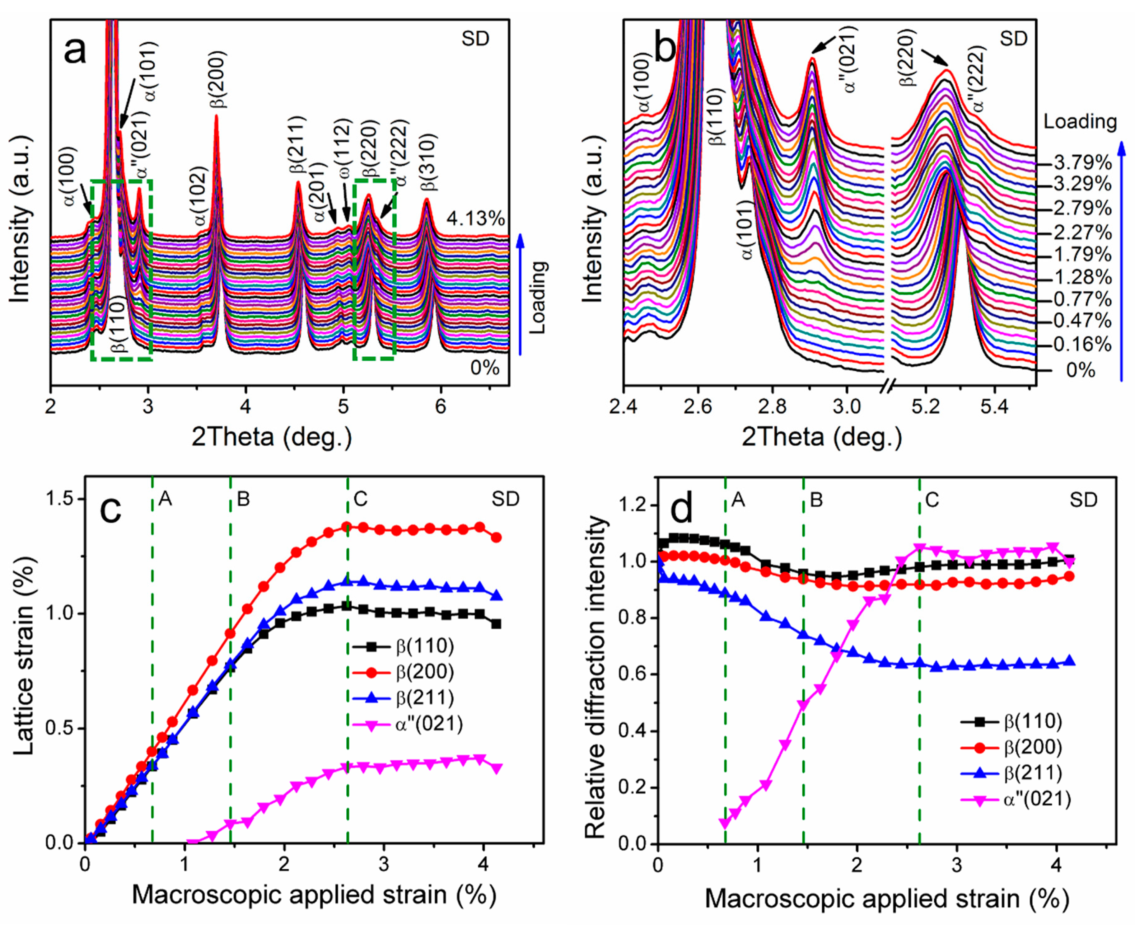
Figure 5a,b show the 1D SXRD spectrums during in situ tensile loading obtained by integrating along a specific direction (SD, φ: 56–76°) of the 2D SXRD patterns. The shift of the diffraction peaks of the β phase towards lower angles indicates that a tensile elastic deformation exits in the SD. The diffraction peaks ascribed to (021)α and (222)α started to appear at certain external strain values, and intensified with the increase in applied strain, demonstrating that gradual SIMT occurred during tensile loading. However, the applied strains for the first appearance of (021)α and (222)α diffraction peaks are 0.67% and 1.46%, respectively, which is different from the results of 1D XRD spectrums along the LD. This implies that the β phase grains with different crystal orientations have different critical stress for SIMT. Besides, the intensity of α” martensite is clearly greater in the SD than that in the LD, suggesting the preferred selection of martensite variants.
Figure 5 show the evolution of the lattice strains and relative integrated diffraction peak intensities for the (110)β, (200)β, (211)β and (021)α” as functions of applied strain in the SD. The d 021 0 of α” martensite is defined to be the d-spacing at an applied strain of 0.88% when the (021)α diffraction peak is strong enough to be fitted for accurate peak position. The evolution of the lattice strains in the SD is similar to that in the LD. In brief, in the stage of O-A-B, the lattice strain–macroscopic applied strain curves are linear for the β phase, reflecting an elastic deformation; in the stage of B-C, the lattice strain–macroscopic applied strain curves deviate from the linearity and the slopes of the curves begin to decrease, indicating a elastoplastic deformation; in the stage of C-D, the lattice strains of all crystal planes remain almost unchanged, suggesting that elastic deformation disappears in the local area under SXRD study. The evolution of the relative integrated intensity of the (021)α diffraction peak indicates that the onset of SIMT corresponds to point A in the tensile stress–strain curve in Figure 3b, which means the deviation from linearity observed in macroscopic stress–strain curve is coincident with the SIMT. This provides direct evidence that the nonlinear deformation behavior of the cold rolled and annealed Ti36Nb5Zr alloy could be attributed to the SIMT during loading.

4. Discussion

4.1. Variant Selection of Stress-Induced Martensite

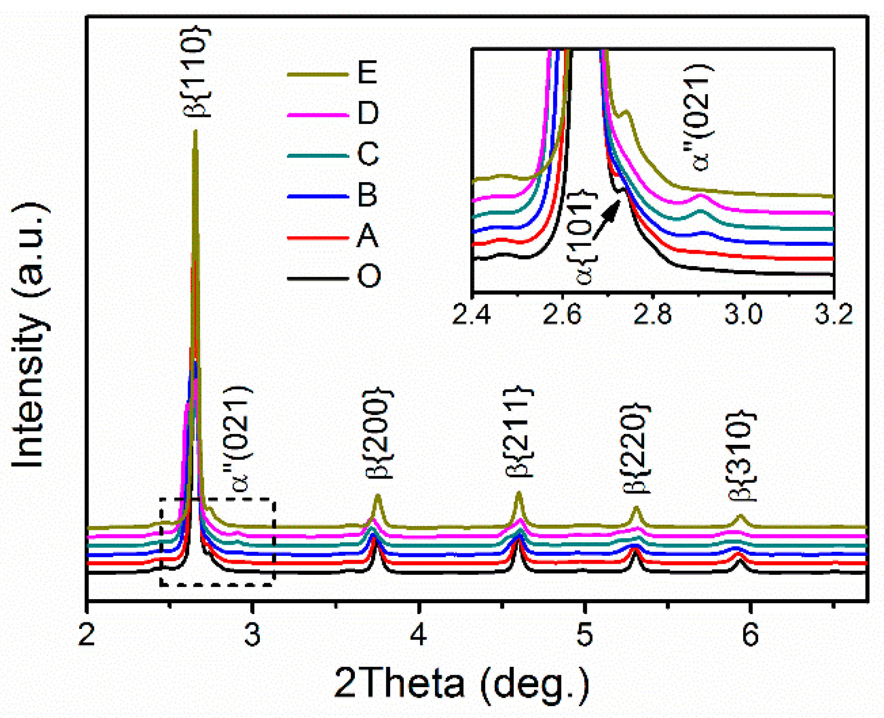
To further explore the detailed scenarios of SIMT, the 2D SXRD patterns at different applied strains (corresponding to points O–E in the macroscopic stress–strain curve in Figure 3b) were unrolled along the full azimuthal circle (0°–360°) and presented in Figure 6. The diffraction lines of the β phase are non-uniform and even discontinuous at zero external strain (O), indicating the existence of strong texture as described above. The diffraction lines curved into “banana” shapes with increasing the applied strain (A–D), indicating that the specimen experiences maximum tension and compression in the longitudinal direction (φ: 90° and 270°) and the transverse direction (φ: 0° and 180°), respectively. Faint shadows ascribed to (021)α appeared at the applied strain corresponding to point A, and evolved into diffraction spots at specific azimuth angles with the increase in external strain (B–D), implying the progressive SIMT during loading. By contrast, the diffraction spots of (222)α formed at higher applied strain and are weaker than those of (021)α. In addition to the diffraction spots of (021)α and (222)α, no α” diffraction spots can be identified from the unrolled 2D SXRD images. Furthermore, it should be emphasized that the intensity of α” martensite is much lower than that of the parent β phase even at the maximum applied strain (point D), which is evidenced by the 1D SXRD spectrums integrated over the entire 360° shown in Figure 7. This suggests the transformed fraction of the β phase is very low, which might be the reason why a nonlinear deformation instead of a yielding plateau is observed during loading of the present Ti36Nb5Zr alloy.
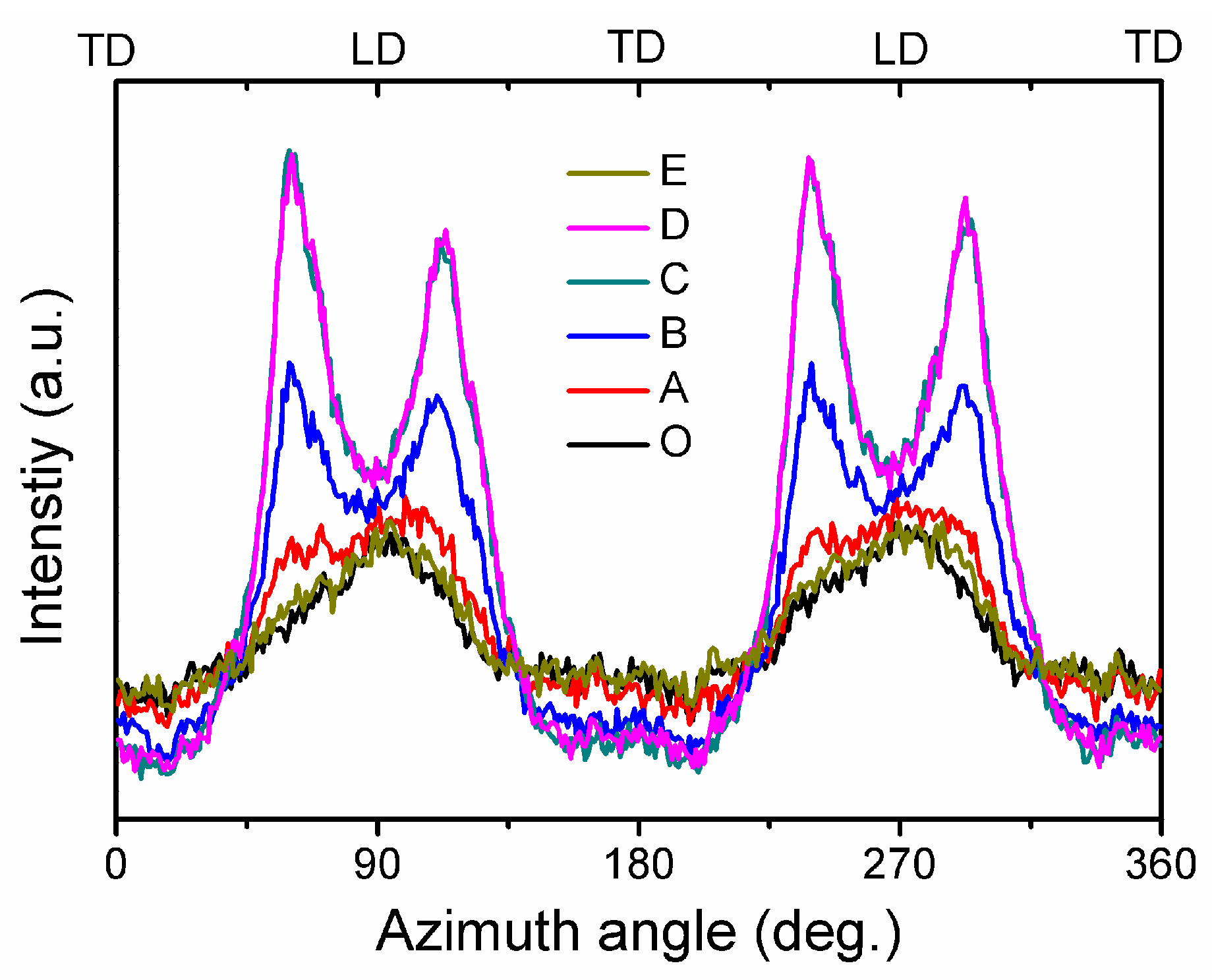
Figure 8 shows the intensity distribution of the (021)α diffraction peak along the azimuth angle at different applied strains corresponding to points O–E in Figure 3b. The curves at applied strains corresponding to points O and E are overlapped, demonstrating the complete reversibility of SIMT in the present alloy. Moreover, the overlap of curves corresponding to points C and D reveals that SIMT did not further occur when the external strain exceeded point C in the local area under SXRD study. The angle between (021)α diffraction peaks and the LD is determined to be 24° ± 3° at the maximum applied strain (corresponding to point D). From the energetics of βα” transformation, the critical stress of SIMT depends on the initial orientation of β grains, and the minimum critical stress can be realized in the β grains that are orientated with a <110> direction along the tensile direction [40]. Moreover, it has been reported that a variant selection operates during SIMT process and only the variants that give a maximum of transformation strain can be formed [36,47]. As mentioned above, the present Ti36Nb5Zr alloy has a texture <110> fiber texture component, i.e., <110>β is parallel to the rolling direction/LD. Therefore, SIMT will first occur in the β grains with <110> parallel to the tensile axis due to their having the lowest critical stress. Furthermore, only one martensitic variant that gives the maximum transformation is activated. The [100]α”, [10]α” and [1]α” crystal orientation of this specific variant are parallel to [1]β, [110]β and [1–10]β, respectively. This implies that the (110)β and (020)α” peaks will appear in the LD of the 2D SXRD patterns and the positions of other α” peaks can be calculated according to the lattice parameters. As only two α” peaks were observed in our measurements, the lattice parameters of α” martensite cannot be calculated for the present alloy. As a solution, the lattice parameters of Gum Metal, which has a similar Nb and Zr content with the Ti36Nb5Zr, were used here, i.e., a = 3.250 Å, b = 4.853 Å and c = 4.740 Å [32]. Based on this assumption, the angle between [20]α” and [21]α” is calculated to be 26°, i.e., the angle between the (021)α peaks and the LD in 2D SXRD diffraction patterns is 26°, which is consistent with the experimental value (24° ± 3°).
As mentioned before, the present Ti36Nb5Zr alloy did not experience complete recrystallization during the annealing process, thus the existence of large amount of defects such as dislocations and grain boundaries resulted in the broadening of β diffraction peaks. Furthermore, the volume fraction of α” martensite is much lower than that of the β phase. Consequently, most α” peaks were either overlapped with β peaks or too weak to be identified from diffraction patterns. According to the PDF card (No. 17-0102), the (021)α peak is one of the second strongest peaks of the α” phase, and the distance between the (021)α peak and the β diffraction peaks is relatively large. This might be the reason why only (021)α diffraction peaks of martensite transformed from β grains with <110> parallel to the tensile axis were observed. In the case of (021)α peaks along the LD and (222)α peaks along both the LD and SD, these martensite variants were transformed from β grains whose <110>β direction is not parallel to the tensile axis. Therefore, higher critical stresses for SIMT are required, which agrees well with the experimental results that the first appearance of these martensitic peaks occurred at higher external strain than the (021)α peak along the LD. Furthermore, the intensities of these peaks are relatively weaker due to the α-fiber texture component in the original β grains.

4.2. Origin of the Recoverable Strain

The cyclic tensile stress–strain curve in Figure 3a indicates that the cold rolled and annealed Ti36Nb5Zr alloy processes a maximum recoverable strain of 2.11%. This is much larger than that of most engineering materials (<0.5%) and is even similar to that of bulk metallic glasses [48,49,50,51], although it is lower than that of superelastic β-Ti alloys whose recoverable strain is mainly realized by SIMT [11]. Considering that the volume fraction of the transformed α” martensite is very low, the direct contribution of SIMT to the recoverable strain in the present alloy should be small. Figure 4c indicates that the lattice strains along the LD for the (110)β, (200)β and (211)β reached maximum values of 2.08%, 1.71% and 1.41% at applied strain of 2.62% (corresponding to point C in macroscopic stress–strain in Figure 3b). It is worth noting that the maximum lattice strain of the (110)β at point C is close to the macroscopic recoverable strain (2.01%) at a similar applied strain (2.5%) to those determined from the cyclic stress–strain curves in Figure 3a. Considering that the present alloy exhibits a strong <110> fiber texture (i.e., (110)β perpendicular to the LD), it is proposed that the recoverable strain of the present Ti36Nb5Zr alloy is mainly contributed by the elastic strain of the β phase. It has been reported that the martensitic transforming alloy can exhibit much larger elastic strain than the conventional dislocation slip alloy [52]. The possibility of SIMT implies the structural instability of the parent phase, and the uniform lattice distortion provided by martensitic transformation can suppress strain localization and damage accumulation [53]. These two characteristics enable alloys that can undergo SIMT to possess large elastic strain. The present Ti36Nb5Zr alloy was designed to have low β phase stability in order to realize low modulus, which provides the possibility of the occurrence of SIMT. In other words, the low β phase stability leads to the large elastic strain that dominated the large recoverable strain of the alloy.

4.3. Microscopic Deformation Mechanisms at Different Macroscopic Applied Strains

Based on the evolution of lattice strains and relative integrated diffraction peak intensities of both the β and α” phases, it is possible to elucidate the activation sequence of each deformation mechanism at different applied strains. This sequence can be summarized on the cyclic and in situ tensile stress–strain curves of the Ti36Nb5Zr alloy, as shown in Figure 9. In the stage of O–A, the deformation was only accommodated by the elastic deformation of the β phase, which corresponds to linear elastic range in the stress–strain curves. In the stage of A–B, SIMT progressively occurred with increasing external strain and the onset of SIMT at point A corresponds to the start of nonlinearity in the stress–strain curves. Besides, the elastic deformation of the β phase continued during this stage. The elastic deformation as well as the reversible SIMT contributed to the fully recoverable strain of 1.5% in the cyclic tensile loading. In the stage of B–C, the SIMT process continued while the β exhibited elastic and plastic deformation simultaneously. These mechanisms provided a ~2.01% recoverable strain at an applied strain of 2.5% during cyclic tensile loading.
In the stage of C–D, the homogeneous plastic deformation evolved into inhomogeneous plastic deformation due to the lack of strain hardening, resulting in plastic strain localization. Romanova et al. have reported that the local strain in the subsection that is far from the one where a neck will form, ceases to develop as soon as plastic strain localizes [54]. Actually, the tensile specimens break near one of the movable grips rather than the center where the synchrotron X-ray beam penetrated into the sample. Therefore, it is believed the plastic deformation of the local area under SXRD study did not continue when the applied strain exceeded point C. That might be why the lattice strains and the relative integrated intensities of all crystal planes remain almost unchanged in the stage of C–D. Although the SXRD experiment was not carried out in the local area of neck formation, it is believed that the plastic deformation continued in this region. On the other hand, the reversible deformation mechanisms including elastic deformation and/or SIMT existed but contributed little to deformation behavior due to the slight increase in the recoverable strain in the stage of C–D. Therefore, it is proposed that plastic deformation dominated the process in the stage of C–D.

5. Conclusions

The deformation mechanisms of the low modulus Ti36Nb5Zr alloy were investigated by in situ SXRD experiments. The following conclusions can be drawn:
(1)
The cold rolled plus annealed Ti36Nb5Zr alloy consists of dominant β phase and a trace of α phase, and has a {001}<110> texture component. During loading, a nonlinear deformation behavior appeared after the loading strain exceeded the linear range limit of ~0.6%, and large recoverable strains of 2.01% and 2.11% were obtained at applied strains of 2.5% and 3.5%, respectively.
(2)
SIMT occurred at an external strain of 0.67% and continued with an applied strain up to 2.67%. Furthermore, the onset of SIMT corresponds to the beginning of the nonlinearity in macroscopic stress–strain curves, indicating that the nonlinear deformation behavior originates from the SIMT. Besides, the α” diffraction spots only appeared at specific azimuth angles on the 2D SXRD patterns, which was caused by the preferred orientation of the original β grains and the stress-induced selections of martensitic variants.
(3)
The large recoverable strain was dominated by the elastic deformation of the β phase, which resulted from the low β phase stability of the Ti36Nb5Zr alloy, whereas the βα” phase transformation strain contributed little to the recoverable strain due to the low volume fraction of the transformed β phase.
(4)
Various deformation mechanisms were activated at different applied strains, including elastic deformation at applied strains of 0–1.46%, SIMT at applied strains of 0.67–2.62%, elastoplastic deformation at applied strains of 1.46–2.62% and plastic deformation at applied strains exceeding 2.62%.

Author Contributions

Conceptualization, Q.M. and X.Z.; methodology, Q.M.; validation, J.Q. and F.W.; formal analysis, K.W.; investigation, H.L.; resources, Y.S. and B.S.; data curation, H.L.; writing—original draft preparation, H.L.; writing—review and editing, Q.M. and X.Z.; visualization, H.L.; supervision, X.Z.; project administration, S.G.; funding acquisition, Q.M. All authors have read and agreed to the published version of the manuscript.

Funding

This research was funded by the Fundamental Research Funds for the Central Universities, grant number 2017QNA04.

Acknowledgments

Qingkun Meng thanks Cun Yu for technical assistance in the in situ synchrotron experiments, and Junsong Zhang for helpful discussions on the deformation mechanisms. The use of the Advanced Photon Source was supported by the U.S. Department of Energy, Office of Science, and Office of Basic Energy Science under Contract No. DE-AC02-06CH11357.

Conflicts of Interest

The authors declare no conflict of interest.

References

  1. Niinomi, M.; Nakai, M.; Hieda, J. Development of new metallic alloys for biomedical applications. Acta Biomater. 2012, 8, 3888–3903. [Google Scholar] [CrossRef]
  2. Chen, L.-Y.; Cui, Y.-W.; Zhang, L.-C. Recent Development in Beta Titanium Alloys for Biomedical Applications. Metals 2020, 10, 1139. [Google Scholar] [CrossRef]
  3. Niinomi, M. Mechanical biocompatibilities of titanium alloys for biomedical applications. J. Mech. Behav. Biomed. Mater. 2008, 1, 30–42. [Google Scholar] [CrossRef] [PubMed]
  4. Zhang, L.-C.; Chen, L.-Y. A Review on Biomedical Titanium Alloys: Recent Progress and Prospect. Adv. Eng. Mater. 2019, 21, 1801215. [Google Scholar] [CrossRef] [Green Version]
  5. Sumner, D.R.; Turner, T.M.; Igloria, R.; Urban, R.M.; Galante, J.O. Functional adaptation and ingrowth of bone vary as a function of hip implant stiffness. J. Biomech. 1998, 31, 909–917. [Google Scholar] [CrossRef]
  6. Geetha, M.; Singh, A.K.; Asokamani, R.; Gogia, A.K. Ti based biomaterials, the ultimate choice for orthopaedic implants—A review. Prog. Mater. Sci. 2009, 54, 397–425. [Google Scholar] [CrossRef]
  7. Li, P.; Ma, X.; Jia, Y.; Meng, F.; Tang, L.; He, Z. Microstructure and Mechanical Properties of Rapidly Solidified β-Type Ti–Fe–Sn–Mo Alloys with High Specific Strength and Low Elastic Modulus. Metals 2019, 9, 1135. [Google Scholar] [CrossRef] [Green Version]
  8. Li, P.; Ma, X.; Wang, D.; Zhang, H. Microstructural and Mechanical Properties of β-Type Ti–Nb–Sn Biomedical Alloys with Low Elastic Modulus. Metals 2019, 9, 712. [Google Scholar] [CrossRef] [Green Version]
  9. Preisler, D.; Janeček, M.; Harcuba, P.; Džugan, J.; Halmešová, K.; Málek, J.; Veverková, A.; Stráský, J. The Effect of Hot Working on the Mechanical Properties of High Strength Biomedical Ti-Nb-Ta-Zr-O Alloy. Materials 2019, 12, 4233. [Google Scholar] [CrossRef] [Green Version]
  10. Biesiekierski, A.; Wang, J.; Abdel-Hady Gepreel, M.; Wen, C. A new look at biomedical Ti-based shape memory alloys. Acta Biomater. 2012, 8, 1661–1669. [Google Scholar] [CrossRef]
  11. Ramezannejad, A.; Xu, W.; Xiao, W.L.; Fox, K.; Liang, D.; Qian, M. New insights into nickel-free superelastic titanium alloys for biomedical applications. Curr. Opin. Solid State Mater. 2019, 23, 100783. [Google Scholar] [CrossRef]
  12. Kim, H.Y.; Ikehara, Y.; Kim, J.I.; Hosoda, H.; Miyazaki, S. Martensitic transformation, shape memory effect and superelasticity of Ti–Nb binary alloys. Acta Mater. 2006, 54, 2419–2429. [Google Scholar] [CrossRef]
  13. Kolli, R.P.; Devaraj, A. A Review of Metastable Beta Titanium Alloys. Metals 2018, 8, 506. [Google Scholar] [CrossRef] [Green Version]
  14. Abdel-Hady, M.; Hinoshita, K.; Morinaga, M. General approach to phase stability and elastic properties of β-type Ti-alloys using electronic parameters. Scr. Mater. 2006, 55, 477–480. [Google Scholar] [CrossRef]
  15. Banerjee, D.; Williams, J.C. Perspectives on Titanium Science and Technology. Acta Mater. 2013, 61, 844–879. [Google Scholar] [CrossRef]
  16. Liang, Q.; Kloenne, Z.; Zheng, Y.; Wang, D.; Antonov, S.; Gao, Y.; Hao, Y.; Yang, R.; Wang, Y.; Fraser, H.L. The role of nano-scaled structural non-uniformities on deformation twinning and stress-induced transformation in a cold rolled multifunctional β-titanium alloy. Scr. Mater. 2020, 177, 181–185. [Google Scholar] [CrossRef]
  17. Sun, F.; Zhang, J.Y.; Marteleur, M.; Gloriant, T.; Vermaut, P.; Laillé, D.; Castany, P.; Curfs, C.; Jacques, P.J.; Prima, F. Investigation of early stage deformation mechanisms in a metastable β titanium alloy showing combined twinning-induced plasticity and transformation-induced plasticity effects. Acta Mater. 2013, 61, 6406–6417. [Google Scholar] [CrossRef] [Green Version]
  18. Chen, Q.J.; Ma, S.Y.; Wang, S.Q. The Nucleation and the Intrinsic Microstructure Evolution of Martensite from {332}<113>(beta) Twin Boundary in beta Titanium: First-Principles Calculations. Metals 2019, 9, 1202. [Google Scholar] [CrossRef] [Green Version]
  19. Hanada, S.; Izumi, O. Correlation of tensile properties, deformation modes, and phase stability in commercial β-phase titanium alloys. Met. Mater. Trans. A 1987, 18, 265–271. [Google Scholar] [CrossRef]
  20. Li, S.; Choi, M.-s.; Nam, T.-h. Effect of thermo-mechanical treatment on microstructural evolution and mechanical properties of a superelastic Ti–Zr-based shape memory alloy. Mater. Sci. Eng. A 2020, 789, 139664. [Google Scholar] [CrossRef]
  21. Miyazaki, S.; Kim, H.Y.; Hosoda, H. Development and characterization of Ni-free Ti-base shape memory and superelastic alloys. Mater. Sci. Eng. A 2006, 438–440, 18–24. [Google Scholar] [CrossRef]
  22. Zhang, J.; Sun, F.; Chen, Z.; Yang, Y.; Shen, B.; Li, J.; Prima, F. Strong and ductile beta Ti–18Zr–13Mo alloy with multimodal twinning. Mater. Res. Lett. 2019, 7, 251–257. [Google Scholar] [CrossRef] [Green Version]
  23. Fu, J.; Yamamoto, A.; Kim, H.Y.; Hosoda, H.; Miyazaki, S. Novel Ti-base superelastic alloys with large recovery strain and excellent biocompatibility. Acta Biomater. 2015, 17, 56–67. [Google Scholar] [CrossRef]
  24. Hao, Y.L.; Li, S.J.; Sun, S.Y.; Zheng, C.Y.; Hu, Q.M.; Yang, R. Super-elastic titanium alloy with unstable plastic deformation. Appl. Phys. Lett. 2005, 87, 091906. [Google Scholar] [CrossRef]
  25. Saito, T.; Furuta, T.; Hwang, J.-H.; Kuramoto, S.; Nishino, K.; Suzuki, N.; Chen, R.; Yamada, A.; Ito, K.; Seno, Y.; et al. Multifunctional alloys obtained via a dislocation-free plastic deformation mechanism. Science 2003, 300, 464–467. [Google Scholar] [CrossRef] [Green Version]
  26. Hao, Y.L.; Li, S.J.; Sun, S.Y.; Zheng, C.Y.; Yang, R. Elastic deformation behaviour of Ti–24Nb–4Zr–7.9Sn for biomedical applications. Acta Biomater. 2007, 3, 277–286. [Google Scholar] [CrossRef]
  27. Zhang, Y.W.; Li, S.J.; Obbard, E.G.; Wang, H.; Wang, S.C.; Hao, Y.L.; Yang, R. Elastic properties of Ti–24Nb–4Zr–8Sn single crystals with bcc crystal structure. Acta Mater. 2011, 59, 3081–3090. [Google Scholar] [CrossRef]
  28. Gutkin, M.Y.; Ishizaki, T.; Kuramoto, S.; Ovid’ko, I.A. Nanodisturbances in deformed Gum Metal. Acta Mater. 2006, 54, 2489–2499. [Google Scholar] [CrossRef]
  29. Cui, J.P.; Hao, Y.L.; Li, S.J.; Sui, M.L.; Li, D.X.; Yang, R. Reversible Movement of Homogenously Nucleated Dislocations in a β-Titanium Alloy. Phys. Rev. Lett. 2009, 102, 045503. [Google Scholar] [CrossRef]
  30. Liang, Q.; Wang, D.; Zheng, Y.; Zhao, S.; Gao, Y.; Hao, Y.; Yang, R.; Banerjee, D.; Fraser, H.L.; Wang, Y. Shuffle-nanodomain regulated strain glass transition in Ti-24Nb-4Zr-8Sn alloy. Acta Mater. 2020, 186, 415–424. [Google Scholar] [CrossRef]
  31. Liu, J.P.; Wang, Y.D.; Hao, Y.L.; Wang, H.L.; Wang, Y.; Nie, Z.H.; Su, R.; Wang, D.; Ren, Y.; Lu, Z.P.; et al. High-energy X-ray diffuse scattering studies on deformation-induced spatially confined martensitic transformations in multifunctional Ti–24Nb–4Zr–8Sn alloy. Acta Mater. 2014, 81, 476–486. [Google Scholar] [CrossRef] [Green Version]
  32. Talling, R.J.; Dashwood, R.J.; Jackson, M.; Dye, D. On the mechanism of superelasticity in Gum metal. Acta Mater. 2009, 57, 1188–1198. [Google Scholar] [CrossRef] [Green Version]
  33. Al-Zain, Y.; Kim, H.Y.; Koyano, T.; Hosoda, H.; Nam, T.H.; Miyazaki, S. Anomalous temperature dependence of the superelastic behavior of Ti–Nb–Mo alloys. Acta Mater. 2011, 59, 1464–1473. [Google Scholar] [CrossRef]
  34. Tahara, M.; Kim, H.Y.; Hosoda, H.; Miyazaki, S. Cyclic deformation behavior of a Ti–26 at.% Nb alloy. Acta Mater. 2009, 57, 2461–2469. [Google Scholar] [CrossRef]
  35. Zhao, C.H.; Kisslinger, K.; Huang, X.J.; Lu, M.; Camino, F.; Lin, C.H.; Yan, H.F.; Nazaretski, E.; Chu, Y.; Ravel, B.; et al. Bi-continuous pattern formation in thin films via solid-state interfacial dealloying studied by multimodal characterization. Mater. Horiz. 2019, 6, 1991–2002. [Google Scholar] [CrossRef]
  36. Zhu, Z.W.; Xiong, C.Y.; Wang, J.; Li, R.G.; Ren, Y.; Wang, Y.D.; Li, Y. In situ synchrotron X-ray diffraction investigations of the physical mechanism of ultra-low strain hardening in Ti-30Zr-10Nb alloy. Acta Mater. 2018, 154, 45–55. [Google Scholar] [CrossRef]
  37. Warchomicka, F.; Canelo-Yubero, D.; Zehetner, E.; Requena, G.; Stark, A.; Poletti, C. In-Situ Synchrotron X-Ray Diffraction of Ti-6Al-4V During Thermomechanical Treatment in the Beta Field. Metals 2019, 9, 862. [Google Scholar] [CrossRef] [Green Version]
  38. Castany, P.; Ramarolahy, A.; Prima, F.; Laheurte, P.; Curfs, C.; Gloriant, T. In situ synchrotron X-ray diffraction study of the martensitic transformation in superelastic Ti-24Nb-0.5N and Ti-24Nb-0.5O alloys. Acta Mater. 2015, 88, 102–111. [Google Scholar] [CrossRef]
  39. Yang, Y.; Castany, P.; Cornen, M.; Prima, F.; Li, S.J.; Hao, Y.L.; Gloriant, T. Characterization of the martensitic transformation in the superelastic Ti–24Nb–4Zr–8Sn alloy by in situ synchrotron X-ray diffraction and dynamic mechanical analysis. Acta Mater. 2015, 88, 25–33. [Google Scholar] [CrossRef]
  40. Morris, J.W.; Hanlumyuang, Y.; Sherburne, M.; Withey, E.; Chrzan, D.C.; Kuramoto, S.; Hayashi, Y.; Hara, M. Anomalous transformation-induced deformation in 〈110〉 textured Gum Metal. Acta Mater. 2010, 58, 3271–3280. [Google Scholar] [CrossRef]
  41. Meng, Q.; Guo, S.; Ren, X.; Xu, H.; Zhao, X. Possible contribution of low shear modulus C44 to the low Young’s modulus of Ti-36Nb-5Zr alloy. Appl. Phys. Lett. 2014, 105, 131907. [Google Scholar] [CrossRef]
  42. Meng, Q.; Zhang, J.; Huo, Y.; Sui, Y.; Zhang, J.; Guo, S.; Zhao, X. Design of low modulus β-type titanium alloys by tuning shear modulus C44. J. Alloys Compd. 2018, 745, 579–585. [Google Scholar] [CrossRef]
  43. Guo, S.; Meng, Q.; Zhao, X.; Wei, Q.; Xu, H. Design and fabrication of a metastable β-type titanium alloy with ultralow elastic modulus and high strength. Sci. Rep. 2015, 5, 14688. [Google Scholar] [CrossRef]
  44. Meng, Q.; Liu, Q.; Guo, S.; Zhu, Y.; Zhao, X. Effect of thermo-mechanical treatment on mechanical and elastic properties of Ti–36Nb–5Zr alloy. Prog. Nat. Sci. 2015, 25, 229–235. [Google Scholar] [CrossRef] [Green Version]
  45. Sander, B.; Raabe, D. Texture inhomogeneity in a Ti–Nb-based β-titanium alloy after warm rolling and recrystallization. Mater. Sci. Eng. A 2008, 479, 236–247. [Google Scholar] [CrossRef]
  46. Hou, F.Q.; Li, S.J.; Hao, Y.L.; Yang, R. Nonlinear elastic deformation behaviour of Ti–30Nb–12Zr alloys. Scr. Mater. 2010, 63, 54–57. [Google Scholar] [CrossRef]
  47. Tahara, M.; Kim, H.Y.; Inamura, T.; Hosoda, H.; Miyazaki, S. Lattice modulation and superelasticity in oxygen-added β-Ti alloys. Acta Mater. 2011, 59, 6208–6218. [Google Scholar] [CrossRef]
  48. Sun, B.B.; Sui, M.L.; Wang, Y.M.; He, G.; Eckert, J.; Ma, E. Ultrafine composite microstructure in a bulk Ti alloy for high strength, strain hardening and tensile ductility. Acta Mater. 2006, 54, 1349–1357. [Google Scholar] [CrossRef]
  49. Chen, X.H.; Lu, J.; Lu, L.; Lu, K. Tensile properties of a nanocrystalline 316L austenitic stainless steel. Scr. Mater. 2005, 52, 1039–1044. [Google Scholar] [CrossRef]
  50. Jeon, C.; Kim, C.P.; Joo, S.H.; Kim, H.S.; Lee, S. High tensile ductility of Ti-based amorphous matrix composites modified from conventional Ti–6Al–4V titanium alloy. Acta Mater. 2013, 61, 3012–3026. [Google Scholar] [CrossRef]
  51. Zhang, J.; Liu, Y.; Yang, H.; Ren, Y.; Cui, L.; Jiang, D.; Wu, Z.; Ma, Z.; Guo, F.; Bakhtiari, S.; et al. Achieving 5.9% elastic strain in kilograms of metallic glasses: Nanoscopic strain engineering goes macro. Mater. Today 2020, 37, 18–26. [Google Scholar] [CrossRef]
  52. Zhang, J.; Hao, S.; Jiang, D.; Huan, Y.; Cui, L.; Liu, Y.; Ren, Y.; Yang, H. Dual Phase Synergy Enabled Large Elastic Strains of Nanoinclusions in a Dislocation Slip Matrix Composite. Nano Lett. 2018, 18, 2976–2983. [Google Scholar] [CrossRef] [Green Version]
  53. Zhang, J.; Liu, Y.; Cui, L.; Hao, S.; Jiang, D.; Yu, K.; Mao, S.; Ren, Y.; Yang, H. “Lattice Strain Matching”-Enabled Nanocomposite Design to Harness the Exceptional Mechanical Properties of Nanomaterials in Bulk Forms. Adv. Mater. 2020, 32, 1904387. [Google Scholar] [CrossRef]
  54. Romanova, V.; Balokhonov, R.; Emelianova, E.; Sinyakova, E.; Kazachenok, M. Early prediction of macroscale plastic strain localization in titanium from observation of mesoscale surface roughening. Int. J. Mech. Sci. 2019, 161–162, 105047. [Google Scholar] [CrossRef]
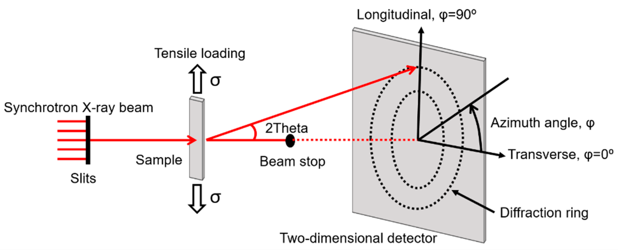
Figure 1. Schematic set-up of in situ synchrotron X-ray experiments.
Metals 10 01619 g001
Figure 2. Structural analysis of the Ti36Nb5Zr alloy before tensile loading. (a) Two-dimensional SXRD pattern of the alloy. (b) One-dimensional SXRD spectrum integrated over the entire 360°. Inset shows the enlarged view of the boxed area in the spectrum. (c) Intensity distributions of the {110}β and {200}β diffraction peaks along the azimuth angle.
Metals 10 01619 g002
Figure 3. Mechanical behavior and SXRD patterns of the Ti36Nb5Zr alloy during tensile loading. (a) Cyclic stress–strain curves with 0.5% strain step. (b) Uniaxial tensile stress–strain curve during in situ SXRD experiment. The 2D SXRD patterns at different applied strains as noted in (b): (c) 4.13% (point D), (d) after fracture (point E). LD, TD and SD in (c,d) are abbreviations of loading direction, transverse direction and specific direction, respectively.
Metals 10 01619 g003
Figure 4. In situ SXRD analysis of the microstructural characteristics of the Ti36Nb5Zr alloy along LD. (a) One-dimensional SXRD spectrums. (b) Enlarged views of the boxed areas in (a). Evolution of the (c) lattice strains and (d) relative integrated diffraction peak intensities of the (110)β, (200)β, (211)β and (021)α crystal planes as functions of the macroscopic applied strain. A, B and C in (c,d) represent the different macroscopic strains noted in Figure 3b.
Metals 10 01619 g004
Figure 5. In situ SXRD analysis of the microstructural characteristics of the Ti36Nb5Zr alloy along SD. (a) One-dimensional SXRD spectrums. (b) Enlarged views of the boxed areas in (a). Evolution of the (c) lattice strains and (d) relative integrated diffraction peak intensities of the (110)β, (200)β, (211)β and (021)α crystal planes as functions of the macroscopic applied strain. A, B and C in (c,d) represent different macroscopic strains noted in Figure 3b.
Metals 10 01619 g005
Figure 6. The unrolled 2D SXRD images along the azimuthal circle (0° to 360°) at different applied strains corresponding to points O–E in Figure 3b.
Metals 10 01619 g006
Figure 7. One-dimensional SXRD spectrums integrated over the entire 360° at different applied strains corresponding to points O–E in Figure 3b. Inset shows the enlarged view of the boxed area in the spectrums.
Metals 10 01619 g007
Figure 8. Intensity distributions of the (021)α diffraction peaks along the azimuth angle at different applied strains corresponding to points O–E in Figure 3b.
Metals 10 01619 g008
Figure 9. Domains of occurrence of different deformation mechanisms noted on conventional stress–strain curves for Ti36Nb5Zr alloy. “def” is the abbreviation of “deformation”.
Metals 10 01619 g009
Publisher’s Note: MDPI stays neutral with regard to jurisdictional claims in published maps and institutional affiliations.