Abstract
The study deals with the investigation of the microstructural constituents of the brazing filler Al-Ag-Cu-Si and the microstructure of brazed aluminum/stainless steel joints. The low liquidus temperature of the Al-Ag-Cu-Si filler of 497 °C allows the joining of the stainless steel and high-strength, thus far non-brazeable aluminum alloys. Brazing was carried out at a temperature of 520 °C in a vacuum furnace. Due to the lower heat input into the liquid brazing filler, the Fe-Al intermetallic layer in the reaction zone of the brazed joints is thin, which is required for good mechanical properties of the joints. The microstructure was studied by scanning electron microscopy (SEM) as well as transmission electron microscopy (TEM) in combination with selected area electron diffraction (SAED). The chemical compositions of the microstructural constituents were analyzed by energy-dispersive X-ray spectroscopy (EDXS). The results have shown that the ternary eutectic microstructure of the brazing filler consists of the α-Al solid solution phase, the θ-Al2Cu phase and a lamelled Ag-Al constituent. During the cooling of the solid filler metal, the Ag2Al phase forms lamellar segregates of μ-Ag3Al with a lamellae thickness of a few nanometers. Thus, the third eutectic constituent is a composition of two phases. The silicon content of the filler metal forms precipitates embedded inside the eutectic cells and in small dimensions inside the cell walls. Moreover, the silicon content prefers the wetting of the stainless steel surface and the formation of the Al7Fe2Si reaction layer with a thickness of 8 µm. The microstructure of the brazing zone is modified in comparison to the solidified pure filler metal. α-Al cells dominate the hypoeutectic structure. Intermetallic phases appear inside the α-cells as well as in the cell walls. Additionally, particles of the reaction phase occur inside the cell walls near the stainless steel. At the interface to the stainless steel in the reaction layer, no cracks or microcracks were detected.
1. Introduction
Eutectic alloys have a great importance both from an academic as well as from a technological point of view. For technological applications such as casting and joining, these systems offer lower melting temperatures than the pure elements and a good fluidity. In the automotive industry, stainless steel and aluminum alloy components are commonly manufactured using Al-Si filler metals [1]. Their liquidus temperature is mostly above the solidus temperature of the most high-strength aluminum alloys (550–600 °C). Hence, the production of brazed joints of stainless steel and higher-strength aluminum alloys is almost impossible. The development of low-melting brazing fillers based on the ternary system Al-Ag-Cu allows the joining of stainless steel with high-strength, up to now non-brazeable aluminum alloys [2]. At present, there is a lot of research that has studied the ternary Al-Ag-Cu system extensively. The structure of ternary eutectic in the Al-Ag-Cu system was investigated by Cooksey et al. [3] and McCartney et al. [4]. Witusiewicz et al. recently optimized the database of thermodynamic parameters for the Al-Ag-Cu system using the CALPHAD method and created a ternary phase diagram, which fits the experimental data well [5]. De Wilde et al. studied the solidification paths of Al-Ag-Cu alloys near the eutectic composition and observed several ternary eutectic morphologies [6,7]. Genau et al. investigated the crystal orientation and morphology in the Al-Ag-Cu ternary eutectic system and identified two different sets of orientation relationships between the three phases formed in the eutectic [8]. Dennstedt et al. developed a measurement method for a clear definition of the interphase spacing and the degree of ordering of these three phases and simulated their relationships in the directionally solidified Al-Ag-Cu ternary eutectic system [9,10]. The microstructure of the developed Al-Ag-Cu brazing filler can be correlated with the microstructure of the studied ternary eutectic alloys. However, the accurate knowledge of the microstructural constituents of the used fillers is important to understand the resulting microstructure of the brazed joints. Grund et al. showed the feasibility arc brazing of stainless steel and aluminum alloys using the brazing filler Al40Ag40Cu20 (wt. %). However, stress-induced cracks occurred at the interface to the stainless steel. Therefore, also brazed joints of aluminum matrix composites and stainless steel could achieve an average tensile shear strength of 20 MPa [11]. The main problem of the low joining strength of the arc brazed joints is the local overheating of the liquid brazing filler, which causes the formation of thick brittle Fe-Al intermetallic layers at the interface to the stainless steel. In comparison to arc brazing, vacuum furnace brazing allows the formation of a thin reaction zone due to the uniform heat input into the whole component, which does not cause an overheating. Consequently, good mechanical properties can be achieved [12]. Moreover, this filler metal was further developed by alloying with Si in order to improve the wetting behavior on the stainless steel and to reduce the melting temperature. At a Si content of 1.5 wt. %, the wetting angle decreases by 40% in comparison to the Al40Ag40Cu20 brazing filler. Furthermore, the melting temperature drops by 10 K to 497 °C [13]. The main aim of the present study is the accurate determination of the microstructure of the modified Al-Ag-Cu-Si brazing filler as well as the microstructural characterization of the aluminum/stainless steel joint.
2. Materials and Methods
Aluminum alloy (AA2017) sheets with dimensions of 5 × 20 × 1.5 mm3 and austenitic stainless steel (AISI 304) sheets with dimensions of 40 × 20 × 1.5 mm3 were used as base materials. The chemical compositions of the used materials are presented in Table 1.

Table 1.
Chemical composition of the used materials.
The Al-Ag-Cu-Si filler was applied as a melt spun foil. The thickness of the produced joints was adjusted at 70 μm by the thickness of the foil. In previous work, it was found that single lap joints of stainless steel and aluminum failed in the Al base material [14]. Therefore, no information about the properties of the joint was possible. The optimized sample geometry uses a double lap joint of stainless steel with aluminum in between, as shown in Figure 1. This sample form allows the accurate determination of the mechanical properties of the brazed joint, because the influence of the mechanical properties of the aluminum base material was reduced [15]. This is necessary for further mechanical testing of the brazed joints.

Figure 1.
Investigated material combination, produced using a filler foil.
The aluminum/stainless steel joints were brazed at a temperature of 520 °C in a vacuum furnace. This temperature was chosen with regard to the melting temperature of the filler of 497 °C and the solidus temperature of the Al base material of 550 °C. The heating process with a heating rate of 10 K/min and the holding process with a holding time of 10 min were carried out in vacuum. The cooling process with a cooling rate of 10 K/min was performed in an argon atmosphere. The brazing temperature was measured by a thermocouple K type, attached in the base material slightly below the brazed surface. Isolated brazing filler was melted and cooled under identical process conditions in order to characterize the pure braze metal structure. Cross sections of the brazed samples were produced in order to investigate the microstructure and to check the formation of the cracks after the brazing process. Sample preparation was done by mechanical grinding and polishing as well as mechanical thinning followed by ion polishing. Microstructural investigations were done using scanning electron microscopes Zeiss Leo 1455VP and Zeiss Neon 40 (Carl Zeiss Microscopy GmbH, Jena, Germany) as well as transmission electron microscope Hitachi H8100 (Hitachi High-Tech Europe GmbH, Mannheim, Germany). The chemical composition of the microstructural constituents was analyzed by energy-dispersive X-ray spectroscopy Ametek Genesis MK2 (AMETEK GmbH, Meerbusch, Germany) in SEM as well as in TEM.
3. Results
3.1. Microstructural Constituents of the Al-Ag-Cu-Si Brazing Filler
The microstructure of the Al-Ag-Cu-Si brazing filler is presented in Figure 2. Similar to the results of the Al-Ag-Cu ternary eutectic microstructure in previous work [2,3,12], the eutectic structure consists of the following phases: the α-Al solid solution (dark gray), an Ag-Al phase (light) and an Al-Cu phase (light gray). In addition, Si precipitates (black) are formed in the eutectic structure because the brazing filler contains 1.5 wt. % of silicon. These precipitates occur as polyhedral particles embedded inside the eutectic cells (Figure 2a) and in small dimensions inside the cell walls (Figure 2b).
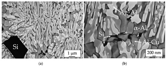
Figure 2.
SEM images of the eutectic microstructure of the Al-Ag-Cu-Si brazing filler with (a) polyhedral Si particles, (b) small Si particles in the eutectic cell wall.
In Figure 3a, a TEM micrograph with all three eutectic constituents is presented. Note, that the gray values of the phases differ from SEM images because the TEM image contrast is caused by electron beam scattering and diffraction. The results of EDXS analyses carried out in TEM are presented in Table 2. In the α-Al solid solution phase 4 at. % Ag were detected, which is reasonable, because there is a high solubility of silver in aluminum. The chemical composition of the Al-Cu phase corresponds to θ-Al2Cu. However, it can be seen, that the detected chemical composition of the Ag- Al constituent does not match clearly the composition of ζ-Ag2Al. Furthermore, the Ag-Al constituent shows aligned stripes in the TEM images as a special structural feature. Both results can be explained in regard to the binary phase diagram of the Ag-Al system, Figure 3b. During the cooling of the melt ζ- Ag2Al will be formed as the first Ag-Al phase. However, at lower temperatures segregation inside the ζ-crystals can be expected. Therefore, the stripes may be explained as lamellae of μ-Ag3Al inside the ζ-Ag2Al grain.
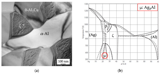
Figure 3.
(a) Transmission electron microscopy (TEM) image of the eutectic constituents of the Al-Ag-Cu-Si brazing filler, (b) binary phase diagram of the Ag-Al system according to [16].

Table 2.
Local energy-dispersive X-ray spectroscopy (EDXS) analysis of the constituents imaged in Figure 3a.
Further information on the lamelled structure of the Ag-Al constituent was found out by selected area electron diffraction. The TEM micrograph in Figure 4a shows parts of an Ag-Al grain and a neighbored α-Al grain. The corresponding SAED pattern is presented in Figure 4b. The pattern includes spots of three phases: ζ-Ag2Al (yellow) with hexagonal structure [17], α-Al solid solution phase (red) with face centered cubic structure and μ-Ag3Al (green) with complex cubic structure of β-Mn [17]. Whereas the ζ-Ag2Al crystal is [100] oriented the α-Al grain is [110] oriented. The (002) spot of ζ-Ag2Al and the (-11-1) spot of α-Al are identical. Therefore, the orientation relationship ζ (002) ‖ α (-11-1) is evident. The pattern of ζ-Ag2Al is completed with additional diffraction spots, for instance (001), because the crystal lattice contains two kinds of atoms. Additional weak spots besides the (000) primary spot and the (002) spots of the ζ-phase can be assigned to (100) diffraction spots of the µ-Ag3Al crystal. Therefore, it is evident, that the lamellation of the Ag-Al grains is caused by the segregation of the μ-Ag3Al phase during the cooling of the solid brazing filler. The lamella thickness of µ-Ag3Al is limited to a few nanometers. The lamella plane is parallel to the (002) lattice plane of ζ- Ag2Al.
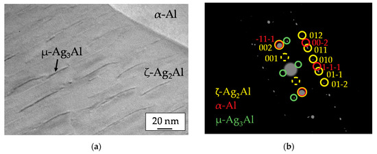
Figure 4.
(a) TEM image of a lamellar Ag-Al grain and a neighbored α-Al grain, (b) SAED pattern of the region shown in the TEM image including some spot indexing.
3.2. Microstructure of the Aluminum/Stainless Steel Brazed Joint
The microstructure and the elemental distribution on the stainless steel side of the joint are presented in Figure 5. The wetting was realized by chemical reaction between liquid filler metal and steel, which causes the formation of a uniform reaction layer. The reaction layer with a thickness of about 8 µm contains aluminum, iron and silicon. Some particles of the reaction phase can be found in the neighbored brazing zone, too. Silicon is mostly bonded in the reaction phase. As reported in the literature, the chemical potential of Si in the Fe-Al-Si ternary system is lower than at the interface to stainless steel substrate. Therefore, Si atoms diffuse and aggregate at the interface to the stainless steel [18].
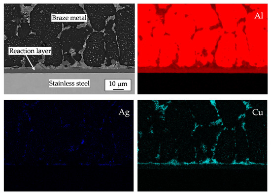
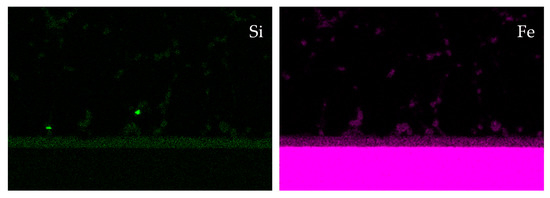
Figure 5.
SEM image and qualitative EDXS elemental distribution of Al, Ag, Cu, Si and Fe on the steel side of the brazed joint.
The braze metal offers a hypoeutectic microstructure with cells of the α-Al solid solution phase. Intermetallic phases can be found inside the cell walls and inside the Al-cells, too. At higher magnification stripes inside the Al-cells can be seen, rectangle in Figure 6. In regard to the binary phase diagram of the Ag-Al system this component can be interpreted as segregated plate-like particles of ζ-Ag2Al.
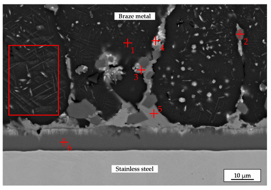
Figure 6.
SEM image of the microstructure of the brazed joint with the EDXS measurement points.
The results of quantitative EDXS measurements on selected locations are presented in Table 3. The analyses indicate, that the α-Al solid solution phase (dark gray) with a low content of Ag (4 at. %), the θ-Al2Cu phase (light gray), the ζ-Ag2Al + μ-Ag3Al compound (light) and the Al7Fe2Si intermetallic (medium gray) with a reduced content of iron are formed in the braze metal. The difference between the detected compositions of ζ + μ grains in TEM (Table 2) and in SEM (Table 3) can be explained by the bigger measuring volume in the case of the compact cross section. Due to the small size of ζ + μ grains, the EDXS result obtained in SEM is affected by the neighbored phases.

Table 3.
Local EDXS analyses on cross section imaged in Figure 6.
The composition of the reaction layer corresponds to the Al7Fe2Si phase. In previous work, it was found, that the Al7Fe2Si layer is also formed at the interface of the aluminum/stainless steel joints, when it is brazed using Al-10Si filler metal [19]. Literature data about the Al–Fe–Si system also confirm this conclusion [20]. Moreover, no cracks or microcracks were detected in the Al7Fe2Si layer at the interface to the stainless steel.
4. Conclusions
The investigation of the microstructural constituents of the brazing filler Al-Ag-Cu-Si has shown that the ternary eutectic microstructure consists of the α-Al solid solution phase, the θ-Al2Cu phase and a lamelled Ag-Al constituent. In addition to former publications [9,10], the TEM study has shown that during cooling of the solid filler metal the Ag2Al phase forms aligned lamellar segregates of μ- Ag3Al with a lamellae thickness of a few nanometers. Thus, the third eutectic constituent is a composition of two phases. The ζ-Ag2Al phase shows an orientation relationship with the α-Al solid solution: ζ (002) ‖ α (-11-1). The atomic planes of the μ- Ag3Al lamellae are rotated by about 90° with regard to ζ (002). The Si content of the filler metal forms precipitates embedded in the eutectic structure.
Aluminum/stainless steel joints produced by vacuum furnace brazing with filler metal Al-Ag-Cu-Si have a thin uniform intermetallic layer at the stainless steel side. The silicon content provides the wetting of the stainless steel surface and the formation of the Al7Fe2Si reaction layer with a thickness of 8 µm. The microstructure of the brazing zone is modified in comparison to the solidified pure filler metal. α-Al cells dominate the hypoeutectic structure. Intermetallic phases appear inside the α-cells as well as in the cell walls. Additionally, particles of the reaction phase occur inside the cell walls in the near of the stainless steel. No cracks or microcracks were detected in the Al7Fe2Si layer at the interface to the stainless steel. In future work, the mechanical properties and the fatigue behavior of the aluminum/stainless steel brazed joints will be investigated.
Author Contributions
Conceptualization, V.F. and H.P.; methodology, V.F., T.U., H.P. and G.W.; formal analysis, V.F., T.U. and H.P.; investigation, V.F., and H.P.; resources, G.W.; writing—original draft preparation, V.F.; writing—review and editing, V.F., T.U., H.P. and G.W.; visualization, V.F. and H.P.; supervision, T.U. and G.W.; funding acquisition, T.U. and G.W. All authors have read and agreed to the published version of the manuscript.
Funding
The publication of this article was funded by Chemnitz University of Technology.
Conflicts of Interest
The authors declare no conflict of interest.
References
- Sierra, G.; Peyre, P.; Beaume, F.D.; Stuart, D.; Fras, G. Steel to aluminium braze welding by laser process with Al–12Si filler wire. Sci. Technol. Weld. Joi. 2008, 13, 430–437. [Google Scholar] [CrossRef]
- Hoyer, I. Entwicklung niedrigschmelzender Lote für hochfeste Aluminiumlegierungen; Abschlussbericht: Chemnitz, Germany, 2011. [Google Scholar]
- Cooksey, D.J.S.; Hellawell, A. The microstructures of ternary eutectic alloys in the Systems Cd—Sn—(Pb, In, Tl), Al-Cu-(Mg, Zn, Ag) and Zn—Sn—Pb. J. Inst. Metals 1967, 95, 183–187. [Google Scholar]
- McCartney, D.G.; Jordan, R.M.; Hunt, J.D. The structures expected in a simple ternary eutectic system: Part II. The Al-Ag-Cu ternary system. Metall. Mater. Trans. 1980, 11, 1251–1257. [Google Scholar] [CrossRef]
- Witusiewicz, V.T.; Hecht, U.; Fries, S.G.; Rex, S. The Ag–Al–Cu system: II. A thermodynamic evaluation of the ternary system. J. Alloys Comp. 2005, 387, 217–227. [Google Scholar] [CrossRef]
- De Wilde, J.; Froyen, L.; Rex, S. Coupled two-phase [α(Al) + θ(Al2Cu)] planar growth and destabilisation along the univariant eutectic reaction in Al–Cu–Ag alloys. Scr. Mater. 2004, 51, 533–538. [Google Scholar] [CrossRef]
- De Wilde, J.; Nagels, E.; Lemoisson, F.; Froyen, L. Unconstrained growth along a ternary eutectic solidification path in Al–Cu–Ag: Preparation of a MAXUS sounding rocket experiment. Mater. Sci. Eng. 2005, 413, 514–520. [Google Scholar] [CrossRef]
- Genau, A.L.; Ratke, L. Crystal orientation and morphology in Al-Ag-Cu ternary eutectic. IOP Conf. Ser. Mater. Sci. Eng. 2012, 27, 012032. [Google Scholar] [CrossRef]
- Dennstedt, A.; Ratke, L.; Choudhury, A.; Nestler, B. New metallographic method for estimation of ordering and lattice parameter in ternary eutectic systems. Metallogr. Microstruct. Anal. 2013, 2, 140–147. [Google Scholar] [CrossRef][Green Version]
- Dennstedt, A.; Choudhury, A.; Ratke, L.; Nestler, B. Microstructures in a ternary eutectic alloy: Devising metrics based on neighbourhood relationships. IOP Conf. Ser. Mater. Sci. Eng. 2016, 117, 012025. [Google Scholar] [CrossRef]
- Grund, T.; Gester, A.; Wagner, G.; Habisch, S.; Mayr, P. Arc brazing of aluminium, aluminium matrix composites and stainless steel in dissimilar joints. Metals 2018, 8, 166. [Google Scholar] [CrossRef]
- Srinivas, V.; Singh, A.K.; Reddy, M. Vacuum brazing of dissimilar tubular component of AA2219 and AISI 304 by a low melting Al-18Ag-20Cu-5Si-0.2 Zn braze alloy. J. Mater. Process. Technol. 2018, 252, 1–12. [Google Scholar]
- Elßner, M.; Weis, S.; Wagner, G.; Grund, T. Joining of material compounds of aluminium matrix composites (AMC) by arc brazing using Al-Ag-Cu system filler alloy. Weld. World 2017, 61, 405–411. [Google Scholar] [CrossRef]
- Fedorov, V.; Weis, S.; Wagner, G. Mechanical and microstructural behavior of brazed aluminum/stainless steel mixed joints. IOP Conf. Ser. Mater. Sci. Eng. 2016, 118, 012003. [Google Scholar] [CrossRef]
- Fedorov, V.; Uhlig, T.; Wagner, G. Investigation of fatigue damage in aluminum/stainless steel brazed joints. Weld. World 2018, 62, 609–616. [Google Scholar] [CrossRef]
- Predel, B. Phase Equilibria, Crystallographic and Thermodynamic Data of Binary Alloys; Springer: Berlin, Germany, 1998. [Google Scholar]
- Villars, P. Inorganic Solid Phases; Springer Materials: Heidelberg, Germany, 2016. [Google Scholar]
- Xia, H.; Zhao, X.; Tan, C.; Chen, B.; Song, X.; Li, L. Effect of Si content on the interfacial reactions in laser welded-brazed Al/steel dissimilar butted joint. J. Mater. Process. Technol. 2018, 258, 9–21. [Google Scholar] [CrossRef]
- Fedorov, V.; Elßner, M.; Uhlig, T.; Wagner, G. Interfacial microstructure and mechanical properties of brazed aluminum/stainless steel—Joints. IOP Conf. Ser. Mater. Sci. Eng. 2017, 181, 012009. [Google Scholar] [CrossRef]
- Du, Y.; Schuster, J.C. A thermodynamic description of the Al-Fe-Si system over the whole composition and temperature ranges via a hybrid approach of CALPHAD and key experiments. Intermetallics 2008, 16, 554–570. [Google Scholar] [CrossRef]
Publisher’s Note: MDPI stays neutral with regard to jurisdictional claims in published maps and institutional affiliations. |
© 2020 by the authors. Licensee MDPI, Basel, Switzerland. This article is an open access article distributed under the terms and conditions of the Creative Commons Attribution (CC BY) license (http://creativecommons.org/licenses/by/4.0/).