Article

High Speed Steel with Iron Addition Materials Sintered by Spark Plasma Sintering

by
Marcin Madej
1,*,
Beata Leszczyńska-Madej
2 and
Dariusz Garbiec
3
1
Faculty of Metals Engineering and Industrial Computer Science, AGH University of Science and Technology, 30 Mickiewicza Ave., 30-059 Krakow, Poland
2
Faculty of Non-Ferrous Metals, AGH University of Science and Technology, 30 Mickiewicza Ave., 30-059 Krakow, Poland
3
Łukasiewicz Research Network – Metal Forming Institute, 14 Jana Pawla II St., 61-139 Poznan, Poland
*
Author to whom correspondence should be addressed.
Metals 2020, 10(11), 1549; https://doi.org/10.3390/met10111549
Submission received: 25 September 2020 / Revised: 18 November 2020 / Accepted: 19 November 2020 / Published: 21 November 2020
(This article belongs to the Special Issue Recent Advances in Field-Assisted Sintering Technologies)

Abstract

:
Attempts were made to describe the effect of the sintering temperature and pure iron powder addition on the properties of high speed steel based materials produced by the spark plasma sintering technique. After sintering, their density, hardness, flexural strength, and tribological properties were determined. The sintered materials were also subjected to microstructural analysis in order to determine the phenomena occurring at the particle contact boundaries during sintering. Based on the analysis of the obtained results, it was found that the mechanical properties and microstructure were mainly influenced by the sintering temperature. Using the temperature of 1000 °C allowed materials with a density close to the theoretical density to be obtained, characterized by a high hardness of about 360 HB and a low wear rate of about 1E-07 g/s.

1. Introduction

High speed steels (HSSs) are materials that have been known for years and are produced in two ways—traditionally and, since around 1965, by powder metallurgy (PM) technology [1,2]. Some of the applications of tools and HSSs produced by PM are in conditions where the priority is good wear resistance, even at higher temperatures. Examples include cam followers, valve seat inserts, and oil pump components. In these applications, the material must also exhibit resistance to oxidation, as well as high hot strength and hardness. Typical single or double-sided cold pressing and subsequent sintering in the vacuum of HSSs to full density is a technique that has been known for several decades [3,4,5]. Some authors also present the possibility of using the addition of carbides (TiC, TaC, WC) to improve sinterability (due to the release of additional carbon) as well as improve the hardness and wear resistance of such materials [3,5,6,7].
In order to obtain products with a final shape by classic powder metallurgy press and sinter, powders with good compressibility and sinterability are required. Even after annealing, tool steel powders (including HSSs powders) can only be pressed to approx. 80% of the theoretical density in most commercial equipment [4,8,9]. A good solution in relation to the presented requirements may be to use a mixture of HSS powders with additives of low-alloy or pure powders, e.g., Höganäs NC100.24 iron powder produced by reduction from ores (all with good compressibility) and their subsequent sintering. Materials of this type can be produced using the basic technique of powder metallurgy–infiltration. Since technological and economic considerations are equally important, the infiltration of a porous skeleton made from HSS with liquid copper has proved to be a sufficient technique by which a fully dense material can be produced at a low cost [4,8,9,10]. Infiltration is an operation in which the pores of PM parts are filled with a molten metal or alloy by means of capillary forces [11,12] or external pressure—pressure infiltration (under pressure exerted from the outside) [13,14].
One of the advanced techniques of powder metallurgy used to produce modern materials or composites is spark plasma sintering (SPS). This technique belongs to the group of field-assisted sintering techniques (FAST) that use the simultaneous effect of compaction pressure for densification and plastic deformation of the powder and a pulsed DC for heating and maintaining the isothermal sintering temperature. The spark discharges occurring in the gaps between particles could cause a local and rapid temperature increase on the surface of the particles. The number of publications on the use of the SPS technique is constantly growing, and increasingly more new materials are produced using this technique. Only a small part of these publications concerns sintered steels or materials or with the addition of steel. Biomaterials, including 316L stainless steel, constitute a significant part of publications in this field of research [15,16,17,18,19]. Marnier et al. [15] showed that the SPS technique could be employed to produce 316L stainless steel without adversely affecting the microstructure. They also proved after further tests that, in terms of corrosion behavior, the samples of fully dense SPSed 316L stainless steel exhibit an increased passive state in chloride media compared to the material produced by traditional methods.
Shashanka [16] studied the non-lubricated sliding wear behavior of duplex and ferritic stainless steel against a diamond indenter in a tribological test. The ball-milled nano-structured stainless steel powders were consolidated by the SPS technique at 1050 °C. It was found that SPS enhances the density, hardness, and wear resistance of both the stainless steels. The SPSed duplex stainless steel was found to exhibit greater hardness and wear resistance than the SPSed ferritic stainless steel.
Pellizzari et al. [20,21] attempted to sinter H13 and M3/2 grade HSS separately, as well as a hot work tool steel and high-speed steel mixed together. They showed that a material with a density close to the theoretical one is obtained after sintering at 1100 °C for 5 min and under the compaction pressure of 60 MPa. The maximum rate of compaction occurs at a lower temperature in H13 steel than in M3/2 HSS, and the increase in hardness and fracture toughness is mainly achieved by increasing the density. The obtained good impact toughness for the SPSed samples with an almost full density is comparable to the reference hot isostatically pressed steels. The authors also proved that the ability to produce hybrid tool steel with properties that can be designed based on the intended specific application is made possible by using a mixture of two grades of steel manufactured to achieve maximum density and uniform distribution of the components. The influence of the phase composition and particle size distribution on the cross-section and oxygen content was assessed on the basis of measurements of the density, hardness, and fracture toughness of the sintered powder mixtures. The authors showed that the mixtures of H13 and M3/2 could be used to obtain hybrid tool steel.
The article presented the results of research on employing the SPS technique to produce HSS materials with the addition of iron powder, which was used to reduce production costs due to its much lower price. In view of the high cost of the major alloying elements used in HSS, the addition of iron powder to HSS seemed to be a good choice; these materials after sintering could be used for non-cutting applications, where high strength was required without the need for a large fraction of free carbides. An additional aim of the article was to verify whether the temperature conditions existing during SPS allow the diffusion and possible dissolution of carbides.

2. Materials and Methods

Water atomized HSS M3/2 grade powder and Höganäs NC 100.24 iron powder, both finer than 150 µm (more than 85% of the particles are less than 75 µm), were used in the experiments. HSS powder was used in the annealed condition. Its chemical composition is shown in Table 1, and its morphology in Figure 1.
In HSSs, the microstructure of the powder particles is very important because due to the low temperatures used during the powder metallurgy production process, it is easy to maintain it in the finished product. Its microstructure consists of fine carbides (MC and M6C types) embedded in a ferritic/bainitic matrix. The typical particle microhardness is 284 ± 17 HV0.065. The microstructures of the used powders are shown in Figure 2.
The powder mixtures of 50 wt% Fe with 50% wt% HSS were prepared by mixing for 30 min in a Turbula T2F (WAB, Muttenz, Switzerland) shaker-mixer and then sintering in an HP D 25/3 (FCT Systeme, Rauenstein, Germany) spark plasma sintering furnace. The on:off ratio of pulsed DC was set at 125:5 (in ms). The powder was sintered using a set of graphite tools under a vacuum of 5 × 10⁻² mbar at sintering temperatures of 900, 950, and 1000 °C and the compaction pressure of 50 MPa. The heating rate was 100 °C/min, and the holding time was 2.5 min. For this purpose, tools made of graphite grade 2333 (Mersen, Gennevilliers, France) were used. The loading chamber in the set of graphite tools was filled with the powder mixture. For technological reasons, Papyex N998 graphite foil (Mersen, Gennevilliers, France) was placed between the powder mixture and the die and the punches. The set of tools prepared in this way was placed in the sintering chamber of the HP D 25/3 furnace in order to carry out the sintering process. Samples with dimensions of Ø40 mm × 10 mm were produced.
The spark plasma sintered samples were subsequently tested for density by the Archimedes method, Brinell hardness (tungsten carbide ball with a diameter of 2.5 mm and 1640 N load), flexural strength, the tribological properties and subjected to microstructural examinations by means of a SU-70 (Hitachi, Tokyo, Japan) scanning electron microscopy. The phase identification of the materials was carried out using a TUR-M62 (Carl Zeiss, Jena, Germany) X-ray diffractometer with CuKα radiation (λ = 1.5406 Å). Three samples were sintered under the same conditions, then the properties were determined for each of them, and next, the standard deviation was calculated. In the three-point flexural test, a rectangular sample is stressed, and the corners are subjected to maximum stresses and strains. Failure will occur when the deformation or elongation exceeds the material limits. The transverse rupture strength (TRS) test was carried out using the three-point flexural method on a ZIM mechanical press. The wear tests were carried out with a T-05 (ITeE, Radom, Poland) block-on-ring tester (Figure 3).
During the test, a rectangular tribological sample was mounted in a holder equipped with a hemispherical insert, ensuring proper contact between the tested sample and a steel ring rotating at a permanent speed. The friction surface (F) of the sample was perpendicular to the load (L) direction. A double lever system was used to push the sample towards the ring with a loading accuracy of ± 1.5%. The wear test conditions were as follows:
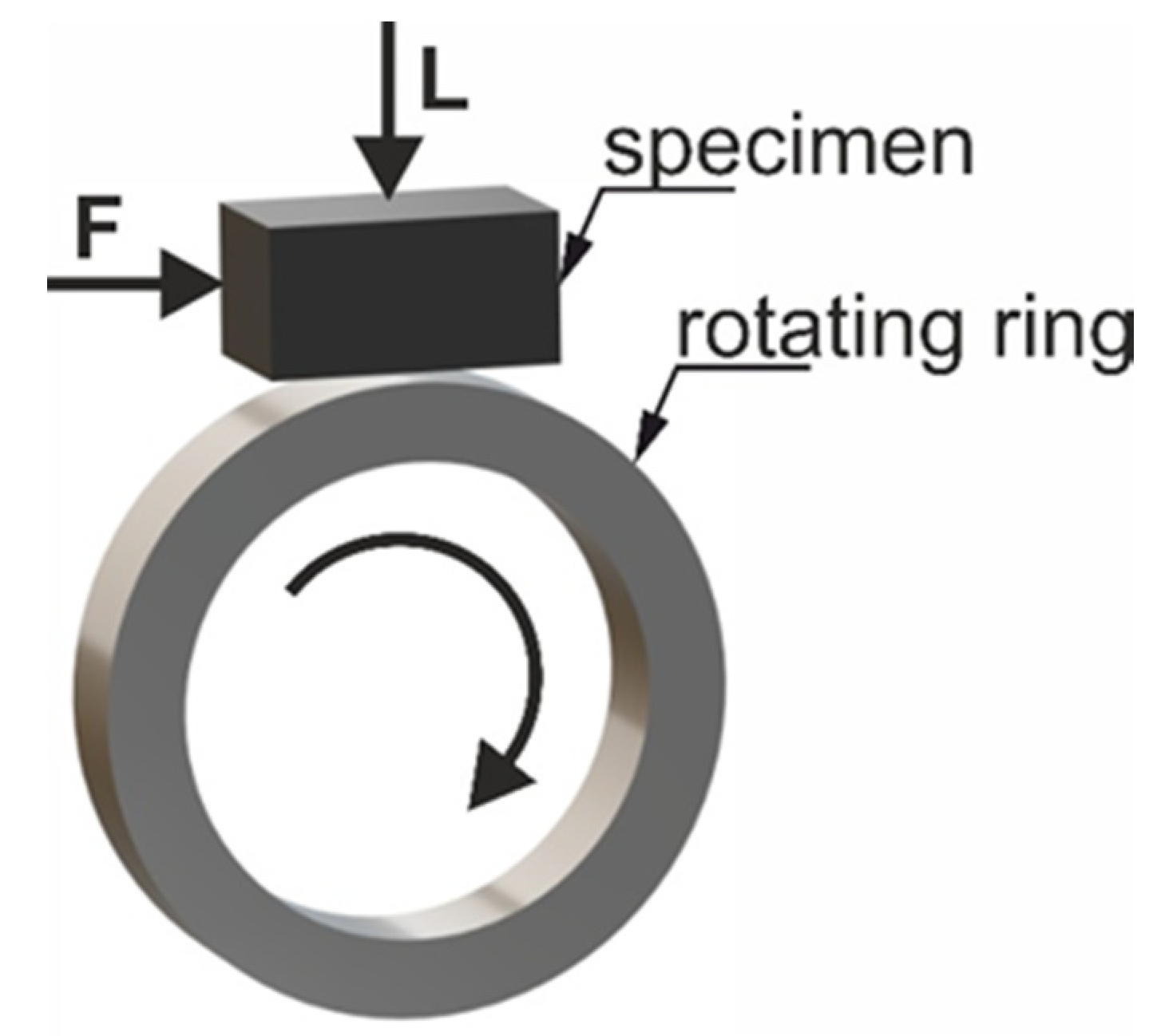
  • dimensions of the test sample: 20 mm × 4 mm× 4 mm,
  • rotating ring: heat-treated steel 100Cr6, 55 HRC, Ø49.5 mm × 8 mm,
  • rotational speed: 136 rpm,
  • velocity: 0.35 m/s,
  • load: 200 N,
  • sliding distance: 250 and 500 m.
The friction coefficient was defined as the ratio of the average friction force (expressed in Newton’s) to the load, expressed in Newton’s. The sample surfaces after the tribological tests were examined under a LEXT OLS 4100 (Olympus, Tokyo, Japan) confocal microscope.

3. Results and Discussion

The first step in the production process is to determine the optimal sintering conditions. The optimal compaction pressure is established as 50 MPa, while the temperature is changed in the range of 900–1000 °C in increments of 50 °C. In the traditional way, a fully dense material made of HSS powders can be obtained by sintering at a temperature close to the solidus line with a sintering window of a maximum of ±5 °C [3].

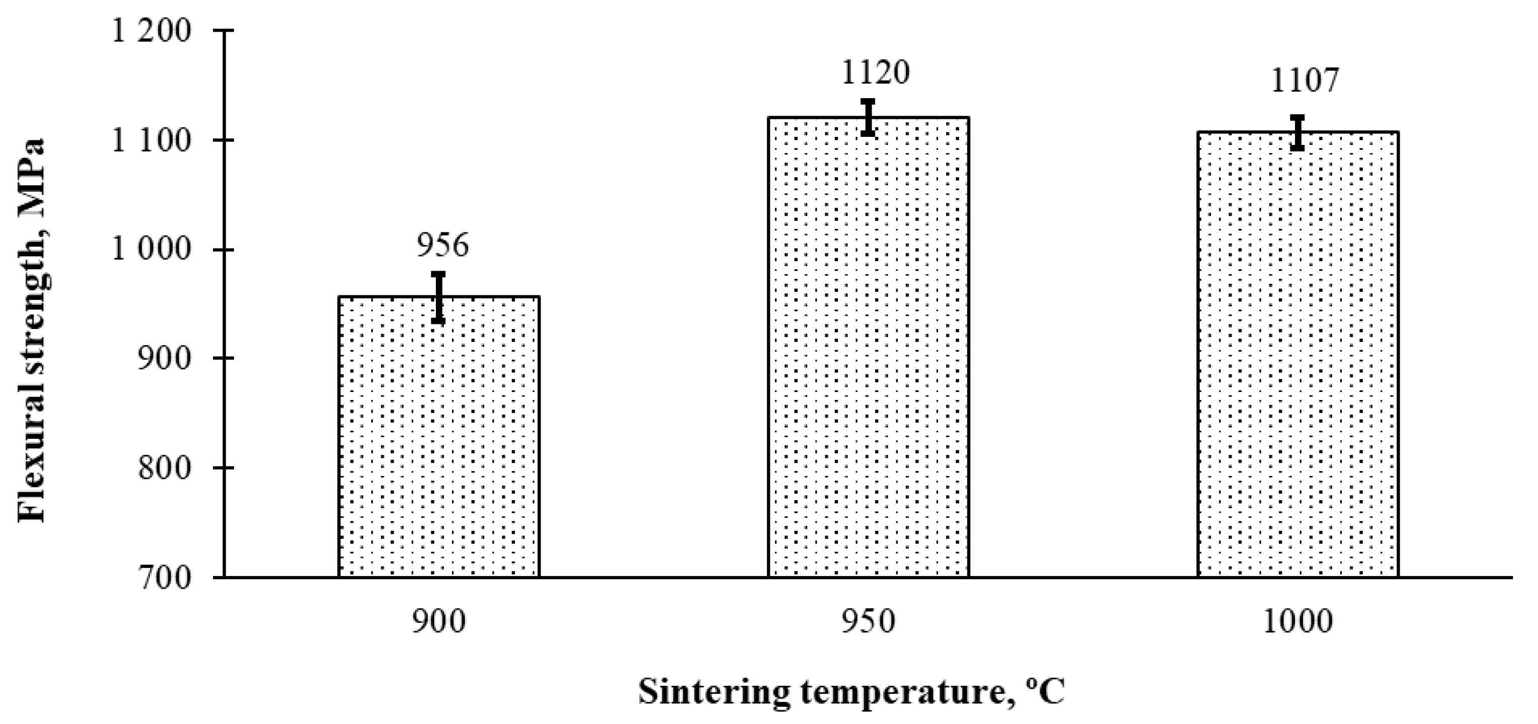
3.1. Density and Hardness
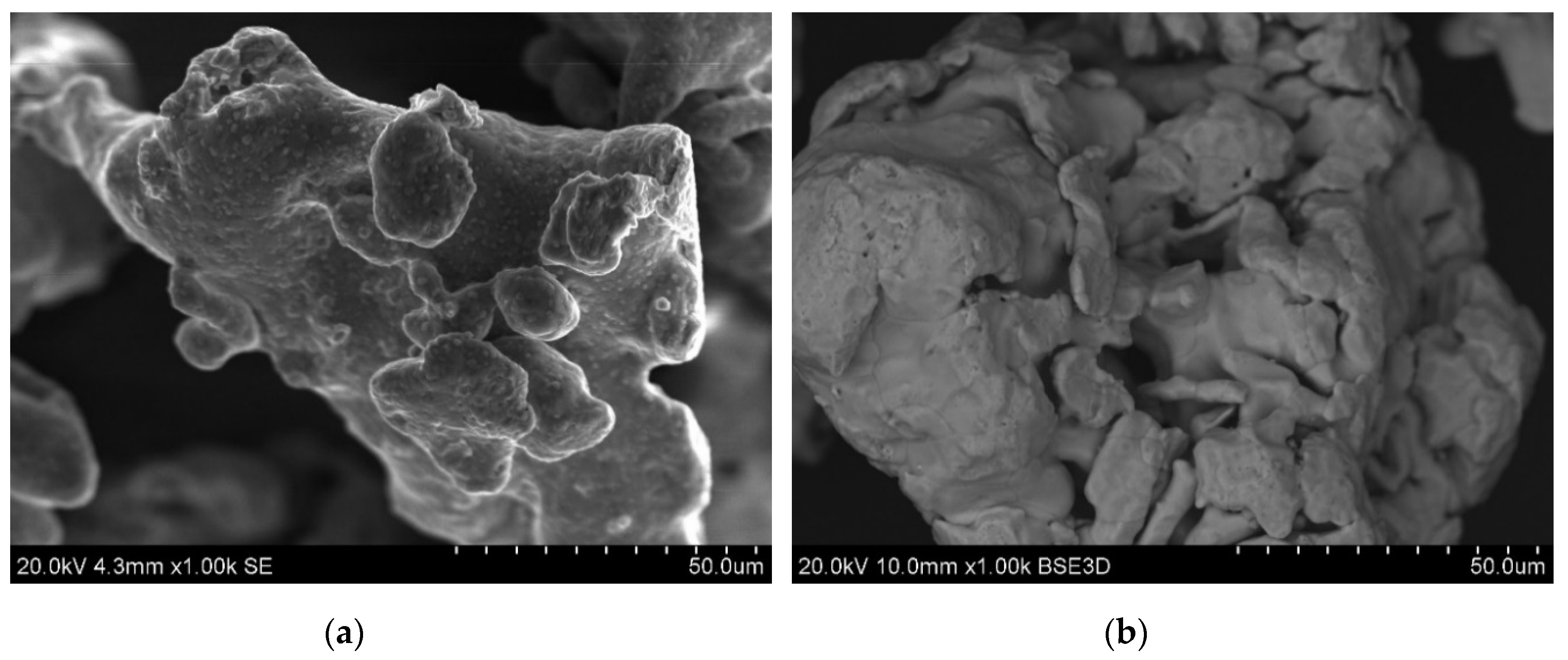
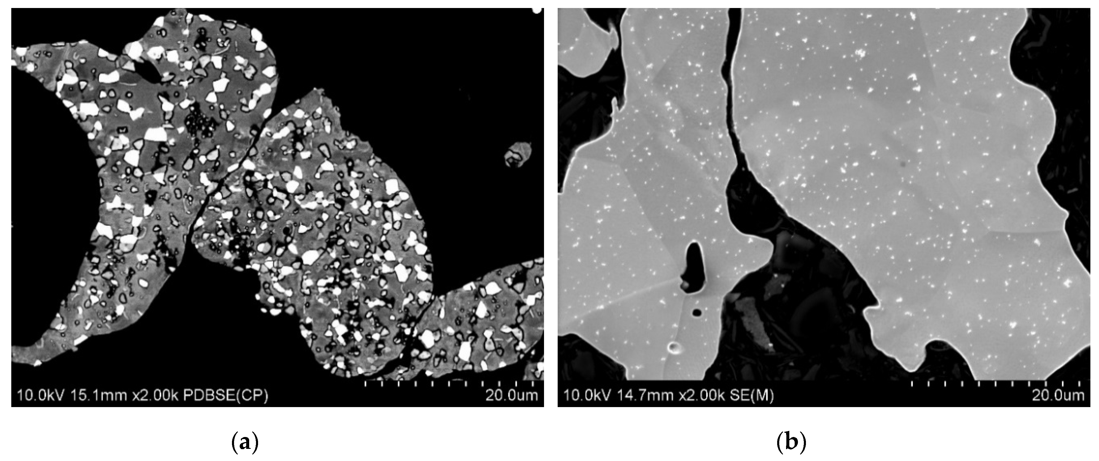
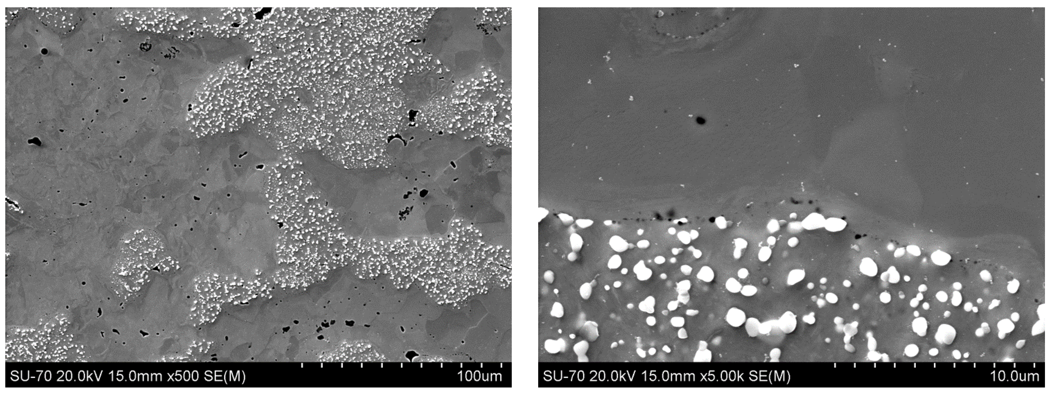
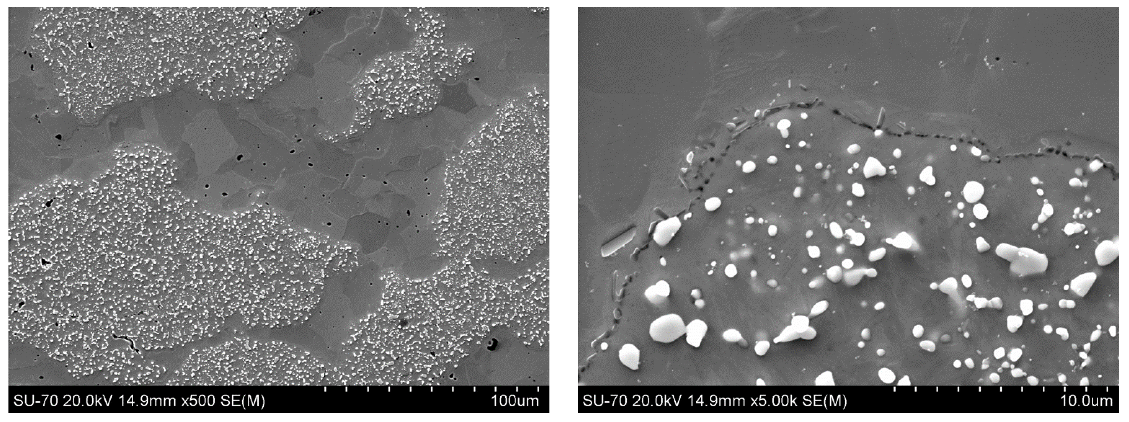
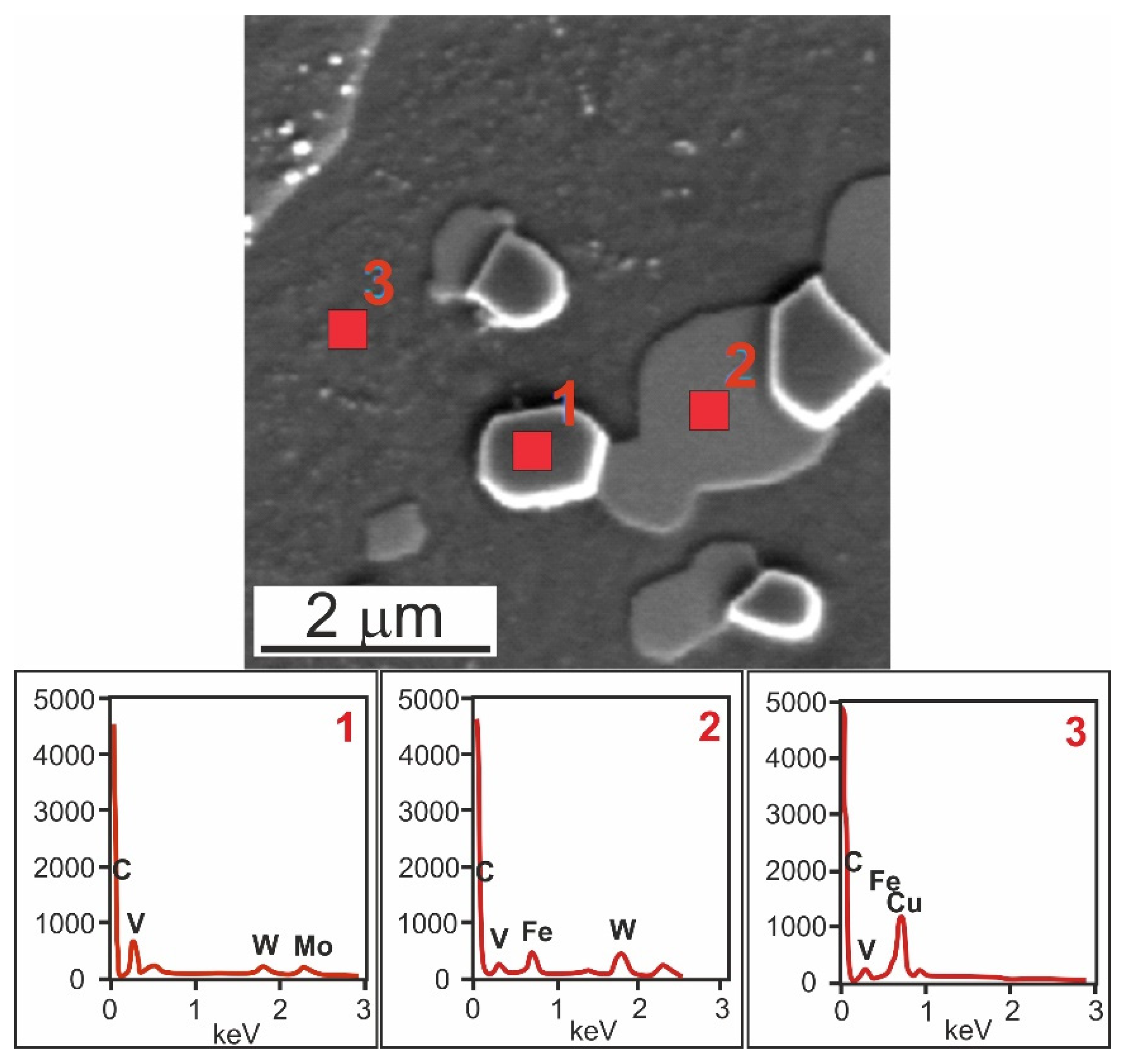
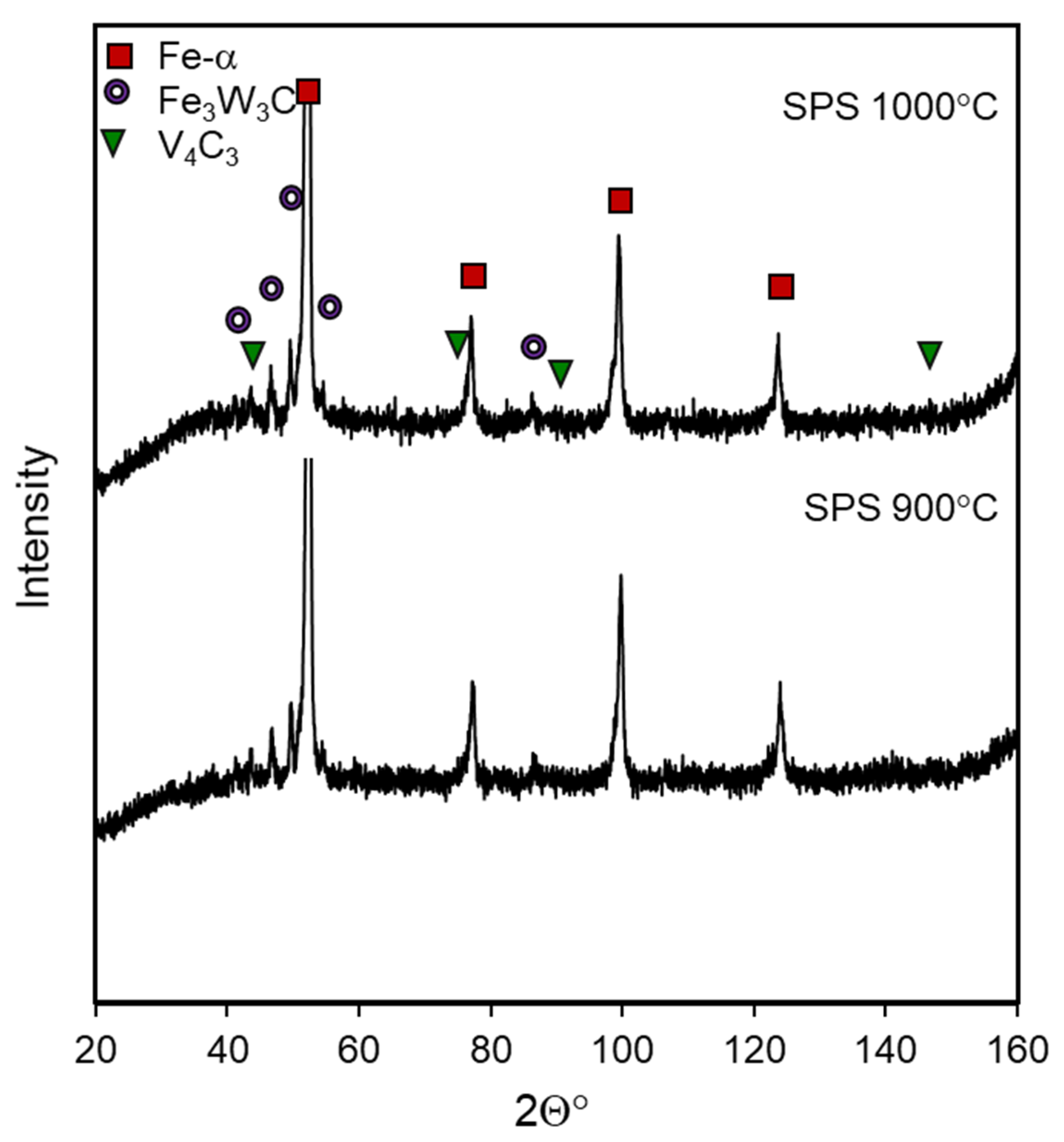
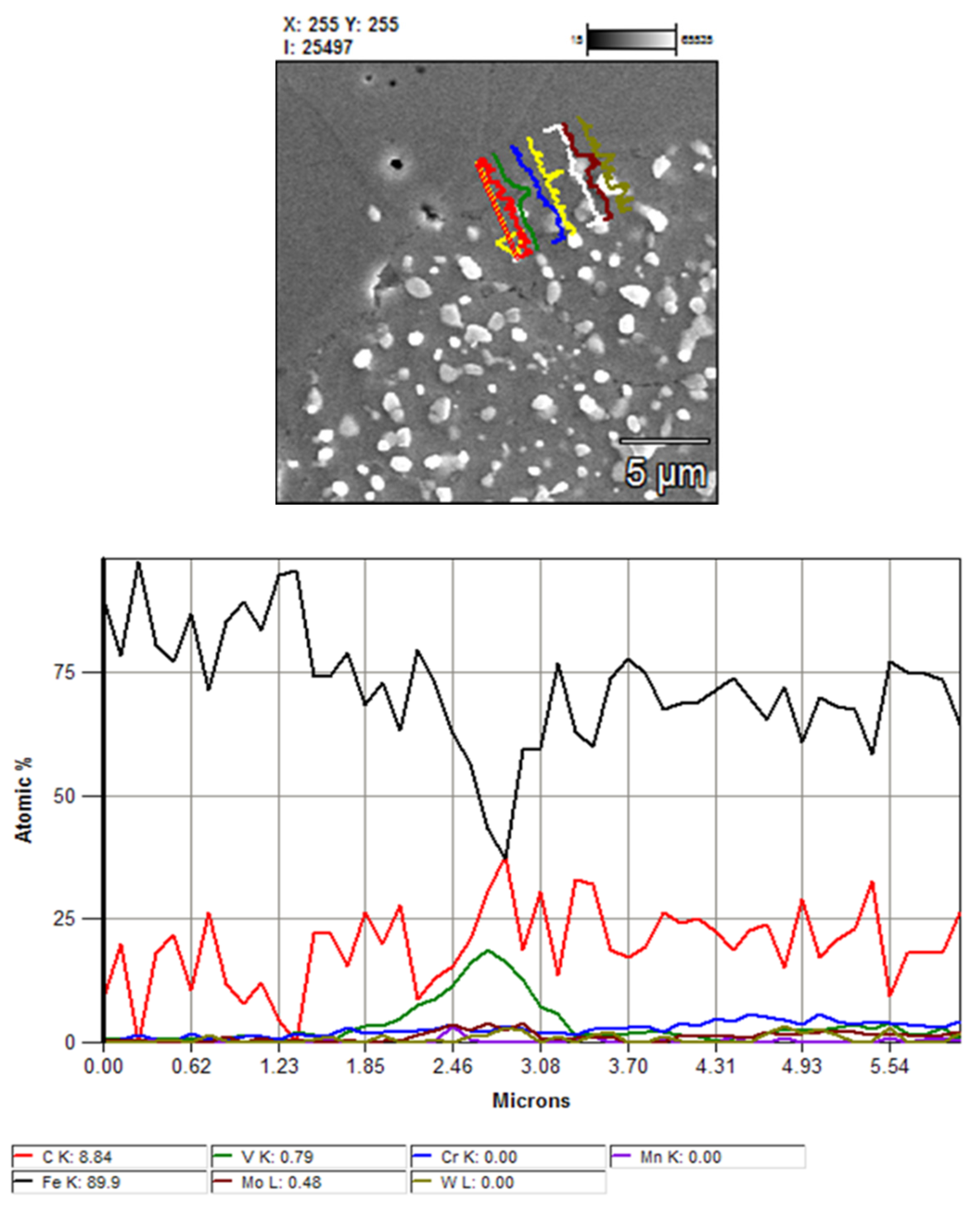
The SPSed samples are tested for properties that allow the proper course of their production to be established. The properties of the SPSed materials are shown in Figure 4, Figure 5 and Figure 6.
Figure 4 presents the relative density of the SPSed materials. As is shown, HSS-Fe materials with a relative density of 92 to 98% (almost a solid material) are obtained by means of SPS. It is clearly shown that the density is a function of the sintering temperature, with a properly selected compaction pressure. Correct selection of the compaction pressure allows better densification at a lower temperature. Most HSSs are materials extremely sensitive to the sintering temperature due to the narrow sintering window, which makes it difficult to select the sintering temperature in the SPS process. The complex phenomena at the grain boundary of the powders, resulting from the flow of pulsed DC during SPS, give rise to the possibility of liquid phase formation, but without the typical phenomena associated with the sintering of supersolidus. Owing to the duration of the impact of the DC pulses, the liquid phase probably disappears quickly; hence, its effect is short-lived; however, with increasing the temperature and simultaneously the compaction pressure, full densification becomes possible. Based on the obtained results, it is confirmed that the sintering temperature of 1000 °C is close to the optimal sintering temperature for the HSS-Fe materials by the SPS technique, as the average relative density is 98%. This temperature is about 250 °C lower than the optimal sintering temperature for M3/2 HSS, in the range of 1245–1255 °C, which is quite a wide sintering window for HSSs [1,14].
As shown in Figure 5, the hardness of the investigated materials depends on their relative density. With its growth from 92 to 98%, the hardness of the materials rises from 273 to 367 HB. These materials made by SPS have a similar hardness to those obtained by sintering and copper infiltration—their hardness is 363 HB [8,9,22]. This is probably due to the shorter holding time and, thus, the limited effect of temperature on the consolidated powder material. The consequence of this may be a lower efficiency of diffusion of the alloying elements from the steel into the iron. In turn, the hardness of the iron has a significant impact on the hardness of the entire material.
Figure 6 presents the results of the flexural strength tests. As in the case with the hardness, the flexural strength also depends mainly on the relative density; with its increase, the flexural strength also increases. Nonetheless, the HSS-Fe materials sintered at 950 and 1000 °C have similar levels of flexural strength. In PM materials, a porosity larger than 5% is a critical value for their mechanical properties. In the studied case, both the materials have a relative density above 95%, and it is also difficult to expect diffusion phenomena during sintering; therefore, their flexural strength is comparable. As the density increases, the importance of the addition of iron also increases as it is ductile, and its main component is ferrite, which has a beneficial effect on the flexural strength.

3.2. Microstructure

The SPSed samples are subjected to microstructural examinations by means of both SEM and X-ray diffraction. Typical SEM microstructures of the sintered materials are shown in Figure 7, Figure 8 and Figure 9.
By analyzing the presented micrographs (Figure 7, Figure 8 and Figure 9), it can be concluded that the microstructure of the materials based on the M3/2 grade HSS with iron addition consists of a steel matrix with finely dispersed carbides, iron particles, and small pores (Figure 7, Figure 8 and Figure 9). It can be seen that when sintering at 900 °C, the pores present in the microstructure of the steel powders (Figure 1a) remain inside the steel grains but increasing the temperature eliminates these pores. Image analysis of the microstructures presented in Figure 7, Figure 8 and Figure 9 shows that the calculated value of the density is correct because the observed pore content corresponds to it. The porosity observed in the micrographs is evenly distributed in the microstructure, usually in the form of small, rounded gaps. Figure 10 shows the uniform distribution of carbides in the sintered HSS matrix of the materials close to the grain boundary between the HSS particles and iron particles. Observations of the contact boundaries at the HSS and iron interface show the presence of a finely dispersive pore network, as shown in Figure 9. This porosity occurs independent of the employed sintering temperature, and it is difficult to conclusively state that its proportion decreases with increasing the sintering temperature. This phenomenon may be caused by a significant proportion of oxygen in the HSS powder. The oxides formed as a result of, for example, carbon steel reduction are closed, and the short holding time prevents their diffusion outside the sintered compact. Detailed analysis of the observed boundary also shows the presence of iron re-melting points, which may indicate the occurrence of a temporary liquid phase during sintering.
Figure 10 confirms the presence of the associated M3 steel, M6C, and MC carbides, as well as the presence of ferrite and bainite in the matrix. The iron is in the steel matrix and dissolved in the visible grey rounded M6C type carbides; tungsten is found in both the M6C and MC carbides, which mainly contain vanadium.
The results of the X-ray analysis shows that the M6C type carbides are complex Fe3W3C compounds, and the MC type carbides are V4C3 type compounds (Figure 11). Comparing these results with the point analysis of the chemical composition of carbides (Figure 10), it can be added that molybdenum is dissolved in M6C type carbides, and tungsten is dissolved in MC carbides. The curves for both the sintering temperatures are almost identical; there are slight differences for the M6C type carbide. This may indicate slight changes in its share in individual sintered materials, which may, however, follow from the dissolution of this carbide near the surface of the powder particles. It may be the effect of exceeding the sintering temperature as a result of the impact of the electric discharges. The linear analysis of the distribution of elements is shown in Figure 12.
The only possibility to enrich the matrix with alloying elements is to dissolve the carbides. It is known that when HSS is heated above 900 °C, the M23C6 carbide begins to dissolve, and this process takes place up to 1100 °C, but M3/2 steel usually has very little or no M23C6 carbide. The dissolution of the M6C type carbides found in the M3/2 HSS starts at 1150 °C, while the MC carbides are stable. From Figure 12, it is evident that there is a diffusion of the carbon, chromium, molybdenum, and manganese from the steel to the iron particles. Nonetheless, Figure 12 shows that slight diffusion of carbon, chromium, molybdenum, and manganese from the steel into the iron particles can be found. These elements diffuse from the matrix of the HSS and partially dissolved carbides of the M6C type, which are near the boundary of the HSS. This dissolution is possible due to the phenomena occurring at the grain boundary during the interaction of DC pulses, causing significant changes in the temperature, often exceeding the designed sintering temperature. The diffusion of these elements during sintering with the addition of iron is increased by the presence of carbon in the solution [14].

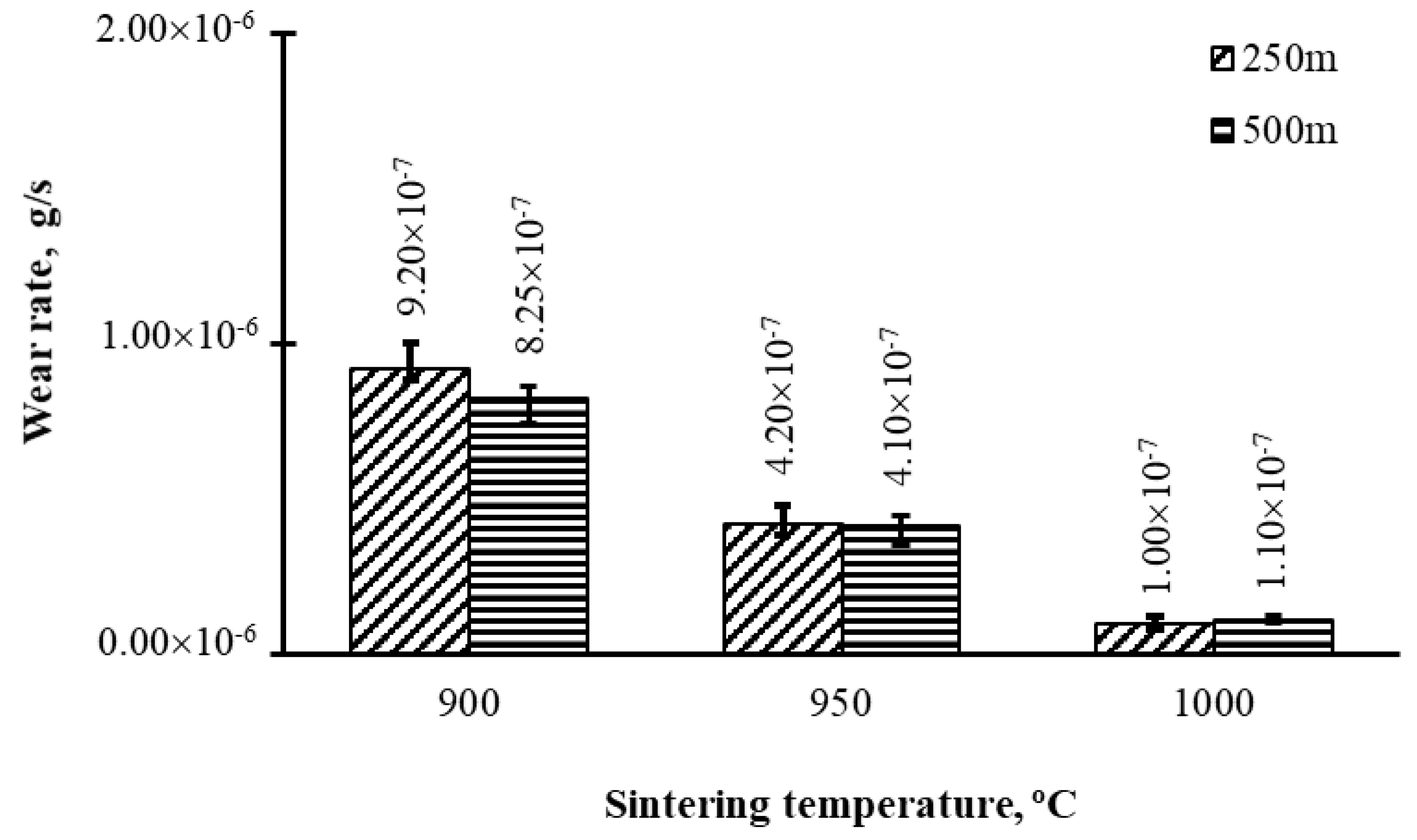
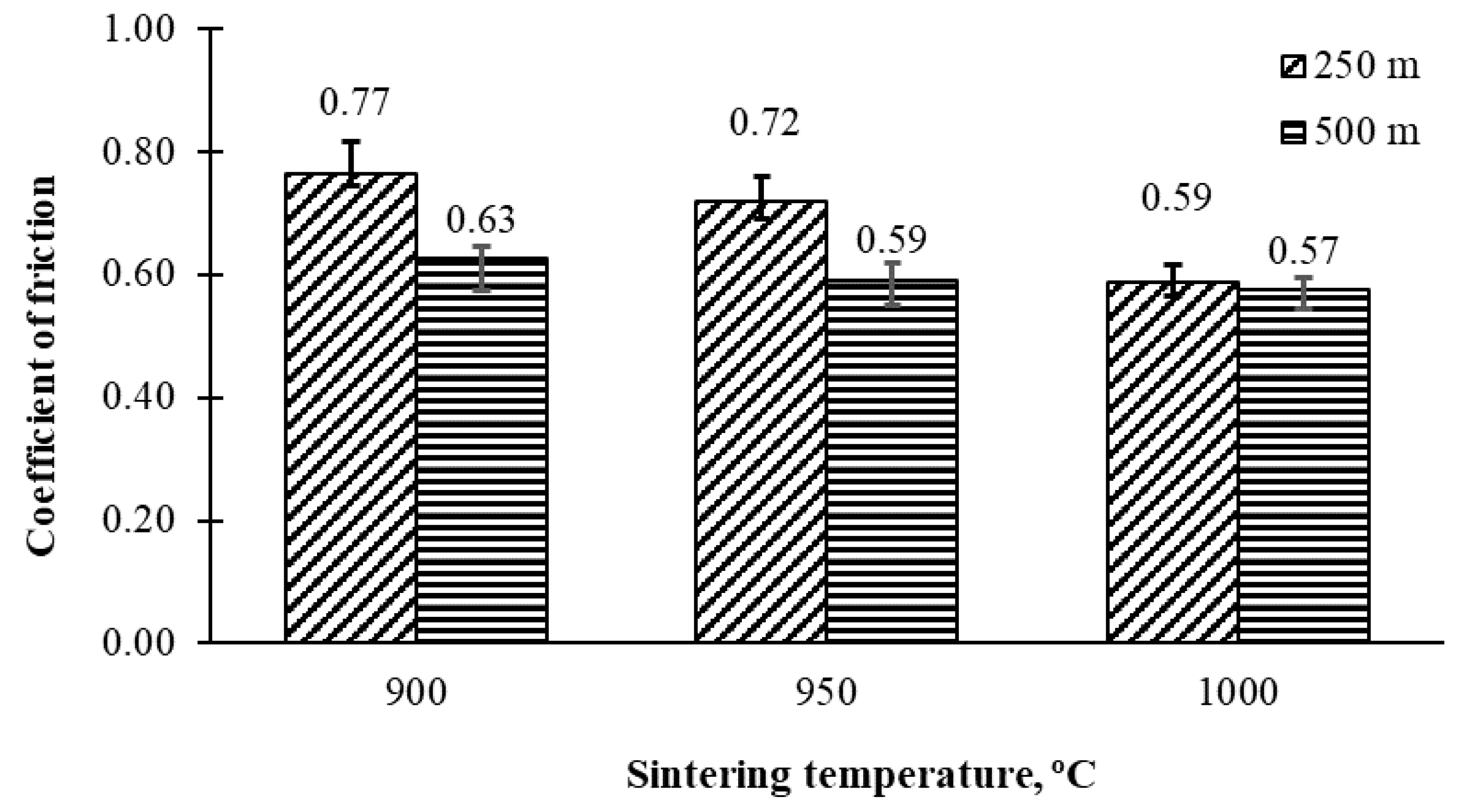
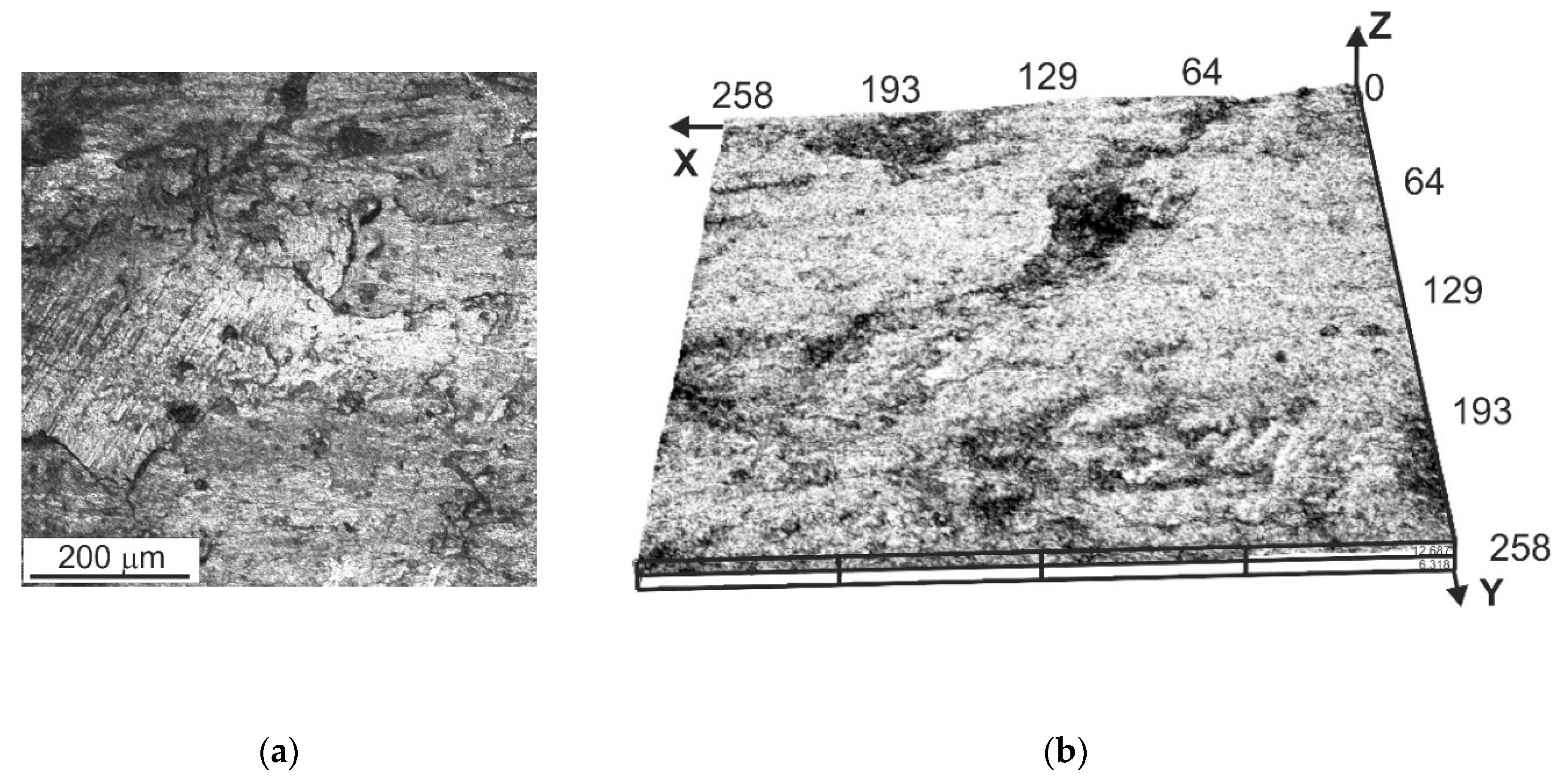
3.3. Tribological Properties

The results obtained during the dry tribological test in accordance with the parameters presented in Section 2 are shown in Figure 13 and Figure 14.
Sintering at the temperature of 1000 °C results in the highest wear resistance and lowest coefficient of friction of all the investigated materials for the parameters used in the test. By comparing the wear resistance of the sintered compacts received by the SPS method, it is evident that the weight loss mainly depends on the densities. The results are similar to those obtained for copper-infiltrated composites of a similar chemical composition [8]. The increasing wear rate of the materials sintered at 900 °C (Figure 13) indicates that the smearing of iron over the surface and filling the pores have a negative effect on the wear resistance. This increases the effective participation of iron in the contact surface of the friction pair and, thus, also the wear mechanisms associated with it. The presence of pores on the friction surface significantly reduces the abrasive wear resistance and has a negative effect on the coefficient of friction. The pores, despite their rounded shape, may increase the tendency of the surface to crack and chip material in micro-areas. The quantity and distribution of high-speed steel on the surface will be responsible for the abrasion resistance; therefore, even distribution of the microstructure components is very important. Characteristic examples of the surface morphology after the tribological test are presented in Figure 15 and Figure 16.
The surface morphologies of the M3/2-50% Fe materials presented in Figure 15 and Figure 16 show the presence of various friction mechanisms. The friction mechanisms change depending on what microstructure components are on the surface; different mechanisms exist in the steel regions (grey areas) and different in the iron regions (brighter areas). It can also be confirmed that the pores are sites of fatigue crack nucleation in the case of the samples sintered at the temperature of 900 °C. This cracking begins much earlier than in this type of material during friction. Figure 15 and Figure 16 show iron smearing on the surface of the M3/2-Fe sintered materials, which implies a significant share of adhesive wear, while the excessive formation of iron oxides can reduce the coefficients of friction but, at the same time, increase the wear exhibited by weight loss. The presence of the addition of iron in the form of relatively pure NC 100.24 powder increases the importance of oxidation during friction in its areas. The dominant wear mechanisms in the area of iron are plowing and microcutting; the elements causing this phenomenon are chromium carbides present in the counter-sample and possibly carbides crushed from the matrix of the HSS. The friction is similar in the areas of steel, but the elements that block the wear are carbides strongly fixed in the steel, especially the MC type.

4. Conclusions

Materials on a matrix of M3/2 HSS with a 50% iron addition obtained by the SPS process at 900, 950, and 1000 °C have a relative density of up to 98%, wherein the density grows with increasing the sintering temperature. The hardness and flexural strength depend on the relative density. The M3/2-50% Fe material obtained at the temperature of 1000 °C has the best densityhardness-flexural strength relation, the relative density of which is 98%, the hardness is 367 HB, and the flexural strength is 1107 MPa. The microstructure of the obtained materials is typical of materials with an HSS matrix. It contains characteristic HSS grains with very fine precipitates of MC and M6C carbides in a ferritic (or ferritic-bainitic) matrix and iron grains. A characteristic feature of the produced materials, occurring independently of the applied sintering temperature, is the very fine pore network on the original external surfaces of the powder particles and the absence of the phenomenon of diffusion of the alloying elements from the steel to the iron. The wear resistance of the tested materials also depends on the sintering temperature. The main factor determining the coefficient of friction and weight loss are pores, their share, and distribution on the surface.

Author Contributions

Conceptualization, methodology and writing—review and editing, M.M., B.L.-M., and D.G.; investigation, B.L.-M. and M.M.; writing—original draft preparation and visualization, M.M. All authors have read and agreed to the published version of the manuscript.

Funding

This research was funded by the Polish State Committee for Scientific Research, grant number 11.11.110.663.

Conflicts of Interest

The authors declare no conflict of interest.

References

  1. Wright, C.S. The production and application of PM high-speed steels. Powder Metall. 1994, 3, 937–944. [Google Scholar]
  2. Dobrzański, L.A.; Matula, G.; Várez, A.; Levenfeld, B.; Torralba, J.M. Structure and mechanical properties of HSS HS6-5-2- and HS 12-1-5-5-type steel produced by modified powder injection moulding process. J. Mater. Process. Technol. 2004, 1, 157–158. [Google Scholar]
  3. Torralba, J.M.G.; Cambronero, J.M.; Ruiz-Pietro, M.M. Sinterability study of PM M2 and T15 HSS reinforced with tungsten and titanium carbides. Powder Metall. 1993, 36, 55–66. [Google Scholar] [CrossRef]
  4. Samal, P.K.; Newkirk, J.W. ASM Handbook: Powder Metallurgy; ASM International: Novelty, OH, USA, 2015; Volume 7, pp. 1–907. [Google Scholar]
  5. Farid, A. Microstructure evolution and wear properties of in situ synthesized TiB2 and TiC reinforced steel matrix composites. J. Alloy. Compd. 2008, 459, 491–497. [Google Scholar]
  6. Gordo, E.; Velasco, F.; Antón, N.; Torralba, J.M. Wear mechanisms in high speed steel reinforced with (NbC)p and (TaC)p MMCs. Wear 2000, 239, 251–259. [Google Scholar] [CrossRef]
  7. Shizhong, W.; Jinhua, Z.; Liujie, X. Effects of vanadium and carbon on microstructures and abrasive wear resistance of high speed steel. Tribol. Int. 2006, 39, 641–648. [Google Scholar]
  8. Madej, M.; Leżański, J. Copper infiltrated high speed steel based composites. Arch. Metall. Mater. 2005, 50, 871–877. [Google Scholar]
  9. Madej, M.; Leżański, J. The structure and properties of copper infiltrated HSS based. Arch. Metall. Mater. 2008, 53, 839–845. [Google Scholar]
  10. Madej, M. The tribological properties of high speed steel based composites. Arch. Metall. Mater. 2010, 55, 61–68. [Google Scholar]
  11. Dobrzanski, L.A.; Matula, G.; Varez, A.; Levenfeld, B.; Torralba, J.M. Fabrication methods and heat treatment conditions effect on tribological properties of high speed steels. J. Mater. Process. Technol. 2004, 157–158, 324–330. [Google Scholar] [CrossRef]
  12. Dobrzańśki, L.A. (Ed.) Fabrication, Structure, Properties and Application of Gradient Sintered Carbide-Steels with HS6-5-2 Matrix. In Powder Metallurgy—Fundamentals and Case Studies; IntechOpen: Rijeka, Croatia, 2017; pp. 199–222. [Google Scholar]
  13. Dobrzański, L.A.; Kloc-Ptaszna, A. Goals and contemporary position of powder metallurgy in products manufacturing. In Powder Metallurgy—Fundamentals and Case Studies; Dobrzańśki, L.A., Ed.; IntechOpen: Rijeka, Croatia, 2017; pp. 1–16. [Google Scholar]
  14. Hoyle, G. High. Speed Steels; Butterworth & Co: Cambridge, UK, 1998; pp. 121–130. [Google Scholar]
  15. Marnier, G.; Keller, C.; Noudem, J.; Hug, E. Functional properties of a spark plasma sintered ultrafine-grained 316L steel. Mater. Des. 2014, 63, 633–640. [Google Scholar] [CrossRef]
  16. Shashanka, R. Non-lubricated dry sliding wear behavior of spark plasma sintered nano-structured stainless steel. J. Mater. Environ. Sci. 2019, 10, 767–777. [Google Scholar]
  17. Hu, Z.; Ning, K.; Lu, K. Study of spark plasma sintered nanostructured ferritic steel alloy with silicon carbide addition. Mater. Sci. Eng. 2016, 670, 75–80. [Google Scholar] [CrossRef] [Green Version]
  18. Tanab, C.; Wangb, G.; Jib, L.; Tonga, Y.; Duanb, X. Investigation on 316L/W functionally graded materials fabricated by mechanical alloying and spark plasma sintering. J. Nucl. Mater. 2016, 469, 32–38. [Google Scholar]
  19. Gyu, L.; Khor, K.A.; Sundararajan, G. Boriding of mild steel using the spark plasma sintering (SPS) technique. Surf. Coat. Technol. 2002, 157, 226–230. [Google Scholar]
  20. Pellizzari, M.; Fedrizzi, A.; Zadra, A. Influence of processing parameters and particle size on the properties of hot work and high speed tool steels by Spark Plasma Sintering. Mater. Des. 2011, 32, 1796–1805. [Google Scholar] [CrossRef]
  21. Pellizzari, M.; Fedrizzi, A.; Zadra, A. Spark Plasma co-Sintering of hot work and high speed steel powders for fabrication of a novel tool steel with composite microstructure. Powder Technol. 2011, 214, 292–299. [Google Scholar] [CrossRef]
  22. Madej, M. Copper infiltrated high speed steel based composites with iron additions. Arch. Metall. Mater. 2009, 54, 1083–1091. [Google Scholar]
Figure 1. SEM morphologies of powders: (a) M3/2 high speed steel, (b) NC 100.24 iron; SEM.
Metals 10 01549 g001
Figure 2. Microstructure of powders: (a) M3/2 high speed steel, (b) NC 100.24 iron; SEM.
Metals 10 01549 g002
Figure 3. Diagram of the test using T-05 tribometer.
Metals 10 01549 g003
Figure 4. Relative densities of spark plasma sintered M3/2–50% Fe materials.
Metals 10 01549 g004
Figure 5. Brinell hardness of spark plasma sintered M3/2–50% Fe materials.
Metals 10 01549 g005
Figure 6. Flexural strength of spark plasma sintered M3/2–50% Fe materials.
Metals 10 01549 g006
Figure 7. The microstructure of M3/2–50% Fe material spark plasma sintered at 900 °C; SEM.
Metals 10 01549 g007
Figure 8. The microstructure of M3/2–50% Fe material spark plasma sintered at 950 °C; SEM.
Metals 10 01549 g008
Figure 9. The microstructure of M3/2–50% Fe material sintered at 1000 °C; SEM.
Metals 10 01549 g009
Figure 10. The microstructure of M3/2–50% Fe material spark plasma sintered at 1000 °C: 1–MC carbides, 2–M6C carbides, 3–HSS matrix; SEM.
Metals 10 01549 g010
Figure 11. XRD diffraction pattern of spark plasma sintered M3/2-50% Fe materials.
Metals 10 01549 g011
Figure 12. Linear analysis of element distribution on iron—high-speed steel boundary.
Metals 10 01549 g012
Figure 13. Wear rate of spark plasma sintered M3/2-50% Fe materials.
Metals 10 01549 g013
Figure 14. Coefficient of friction of spark plasma sintered M3/2-50% Fe materials.
Metals 10 01549 g014
Figure 15. The surface of M3/2-50% Fe materials spark plasma sintered at 900 °C after examining wear resistance: (a) 2D intensity mode, (b) 3D intensity mode.
Metals 10 01549 g015
Figure 16. The surface of M3/2-50% Fe materials spark plasma sintered at 1000 °C after examining wear resistance: (a) 2D intensity mode, (b) 3D intensity mode.
Metals 10 01549 g016
Table 1. Alloying elements and their proportion by weight in M3/2 grade steel.
CCrCoMnMoNiSiVWOFe
1.224.280.380.225.110.330.173.116.230.0626balance
Publisher’s Note: MDPI stays neutral with regard to jurisdictional claims in published maps and institutional affiliations.

